

Page 1
Installations- und Bedienungsanleitung
Installation instruction and
operating manual
Schaltplatine
Switch Circuit Board p. 25
HmIP-PCBS
S. 2
Page 2

Lieferumfang
Anzahl Bezeichnung
1 Homematic IP Schaltplatine
1 Bedienungsanleitung
Dokumentation © 2017 eQ-3 AG, Deutschland
Alle Rechte vorbehalten. Ohne schriftliche Zustimmung des
Herausgebers darf diese Anleitung auch nicht auszugsweise in
irgendeiner Form reproduziert werden oder unter Verwendung
elektronischer, mechanischer oder chemischer Verfahren vervielfältigt oder verarbeitet werden.
Es ist möglich, dass die vorliegende Anleitung noch drucktechnische Mängel oder Druckfehler aufweist. Die Angaben in dieser
Anleitung werden jedoch regelmäßig überprüft und Korrekturen
in der nächsten Ausgabe vorgenommen. Für Fehler technischer
oder drucktechnischer Art und ihre Folgen übernehmen wir keine
Haftung.
Alle Warenzeichen und Schutzrechte werden anerkannt.
Printed in Hong Kong
Änderungen im Sinne des technischen Fortschritts können ohne
Vorankündigung vorgenommen werden.
150437 (web)
Version 1.0 (01/2017)
Page 3

1
A
B
C
D F
E
Page 4
2
3
Page 5
4
Page 6

Inhaltsverzeichnis
1 Hinweise zur Anleitung ................................................... 7
2 Gefahrenhinweise ............................................................ 7
3 Funktion und Geräteübersicht ....................................10
4 Allgemeine Systeminformationen .............................. 11
5 Inbetriebnahme .............................................................. 11
5.1 Einbau .................................................................................... 11
5.2 Anschlussbelegung .............................................................12
5.2.1 Konfiguration mit Open-Collector-Ausgang:...12
5.2.2 Konfiguration mit Relais-Schaltausgang: ...........12
5.3 Anschlussbeispiele...............................................................12
5.4 Anlernen ................................................................................16
6 Bedienung ........................................................................18
7 Fehlerbehebung .............................................................18
7.1 Befehl nicht bestätigt ..........................................................18
7.2 Duty Cycle ............................................................................19
7.3 Fehlercodes und Blinkfolgen ........................................... 20
8 Wiederherstellung der Werkseinstellungen ..............21
9 Allgemeine Hinweise zum Funkbetrieb .....................22
10 Technische Daten ..........................................................23
6
Page 7
Hinweise zur Anleitung
1 Hinweise zur Anleitung
Lesen Sie diese Anleitung sorgfältig, bevor Sie Ihre
Homematic IP Geräte in Betrieb nehmen. Bewahren Sie
die Anleitung zum späteren Nachschlagen auf!
Wenn Sie das Gerät anderen Personen zur Nutzung überlassen, übergeben Sie auch diese Anleitung.
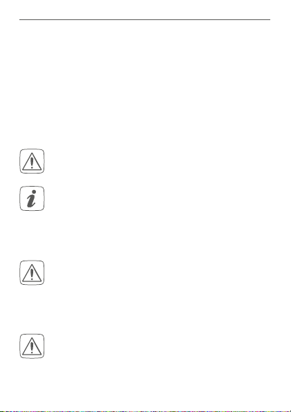
Benutzte Symbole:
Achtung!
Hier wird auf eine Gefahr hingewiesen.
Hinweis.
Dieser Abschnitt enthält zusätzliche wichtige Informationen!
2 Gefahrenhinweise
Für einen ausreichenden Schutz vor elektrostatischen Entladungen ist der Einbau in ein geeignetes Gehäuse erforderlich, damit die Schaltung
nicht durch eine Berührung mit den Fingern oder
Gegenständen gefährdet werden kann.
Das Gerät enthält keine durch den Anwender zu
wartenden Teile. Im Fehlerfall lassen Sie das Gerät
von einer Fachkraft prüfen.
7
Page 8

Gefahrenhinweise
Aus Sicherheits- und Zulassungsgründen (CE) ist
das eigenmächtige Umbauen und/oder Verändern des Gerätes nicht gestattet.
Betreiben Sie das Gerät nur in trockener sowie
staubfreier Umgebung, setzen Sie es keinem Einfluss von Feuchtigkeit, Vibrationen, ständiger
Sonnen- oder anderer Wärmeeinstrahlung, Kälte
und keinen mechanischen Belastungen aus.
Das Gerät ist kein Spielzeug! Erlauben Sie Kindern
nicht damit zu spielen. Lassen Sie das Verpackungsmaterial nicht achtlos liegen. Plastikfolien/
-tüten, Styroporteile etc. können für Kinder zu
einem gefährlichen Spielzeug werden.
Verwenden Sie das Gerät nicht, wenn es von außen
erkennbare Schäden z. B. am Gehäuse, an Bedie
nelementen oder an den Anschlussbuchsen bzw.
eine Funktionsstörung aufweist. Lassen Sie das Ge
rät im Zweifelsfall von einer Fachkraft prüfen.
Bei Sach- oder Personenschäden, die durch unsachgemäße Handhabung oder Nichtbeachten
der Gefahrenhinweise verursacht werden, übernehmen wir keine Haftung. In solchen Fällen erlischt jeder Gewährleistungsanspruch! Für Folgeschäden übernehmen wir keine Haftung!
8
-
-
Page 9

Gefahrenhinweise
Alle Lastangaben beziehen sich auf ohmsche
Lasten! Belasten Sie das Gerät nur bis zur angegebenen Leistungsgrenze. Eine Überlastung kann
zur Zerstörung des Gerätes, zu einem Brand oder
elektrischen Unfall führen. Eine entsprechende
Sicherung ist an den Schaltausgängen (Relais,
Transistor) vorzusehen!
Zur Gewährleistung der elektrischen Sicherheit
muss es sich bei der speisenden Quelle um eine
Sicherheits-Schutzkleinspannung handeln.
Die angeschlossenen Leitungen dürfen eine Länge von 50 cm nicht überschreiten. Die Stromversorgungsleitungen dürfen nur innerhalb trockener Innenräume geführt werden.
Jeder andere Einsatz als der in dieser Bedienungsanleitung beschriebene ist nicht bestimmungsgemäß und führt zu Gewährleistungs- und
Haftungsausschluss. Dies gilt auch für Umbauten
und Veränderungen.
Das Gerät ist für Sie wartungsfrei. Überlassen Sie
eine Wartung oder Reparatur einer Fachkraft.
Das Gerät ist nur für den Einsatz in wohnungsähnlichen Umgebungen geeignet.
9
Page 10

Funktion und Geräteübersicht
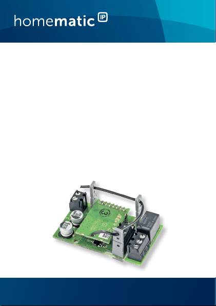
3 Funktion und Geräteübersicht
Die Homematic IP Schaltplatine ermöglicht das Schalten
von bspw. eines Schalter- oder Tastereingangs, 12 V-Signalgebers oder von LEDs per Funk im Kleinspannungsbereich. Die Platine ist für den Betrieb an einer permanenten
Stromversorgung vorgesehen.
Der Schaltausgang der Platine bietet folgende Verwendungsmöglichkeiten:
Das Gerät verfügt über ein Miniatur-Relais mit einer
Schaltleistung bis 30 V/1 A.
Wird dies nicht benötigt, lässt sich der entsprechende
Teil einfach vom Modul abtrennen und stattdessen nur
der Open-Collector-Schaltausgang nutzen. Der OpenCollector-Schaltausgang ermöglicht das Schalten von
Lasten bis zu einer Schaltspannung von 30 V und einem
Schaltstrom bis 0,5 A. Er kann für das Schalten externer
Relais, von Lasten und zur Ansteuerung elektronischer
Schaltungen eingesetzt werden.
Geräteübersicht (s. Abbildung 1):
(A) Geräte-LED
(B) Systemtaste
(C) Betriebsspannung
(D) Befestigungslöcher
(E) Open-Collector-Schaltausgang
(F) Relais-Schaltausgang
10
Page 11

Allgemeine Systeminformationen
4 Allgemeine Systeminformationen
Dieses Gerät ist Teil des Homematic IP Smart-Home-Systems
und kommuniziert über das HomematicIP Funkprotokoll.
Alle Geräte des Systems können komfortabel und individuell
per Smartphone über die Homematic IP App konfiguriert
werden. Alternativ haben Sie die Möglichkeit, HomematicIP
Geräte über die Homematic Zentrale CCU2 oder in Verbindung mit vielen Partnerlösungen zu betreiben. Welcher
Funktionsumfang sich innerhalb des Systems im Zusammenspiel mit weiteren Komponenten ergibt, entnehmen Sie
bitte dem HomematicIP Anwenderhandbuch. Alle technischen Dokumente und Updates finden Sie stets aktuell unter
www.eQ-3.de.
5 Inbetriebnahme
5.1 Einbau
Bitte lesen Sie diesen Abschnitt erst vollständig,
bevor Sie mit dem Einbau beginnen.
Die Platine ist ein Einbaumodul und kann über die Befestigungslöcher (D) einfach in eigene Aufbauten integriert
werden. Beachten Sie dazu die Hinweise zum Gehäuseeinbau in Kapitel „2 Gefahrenhinweise“ auf Seite 7
und die folgenden Leitungsquerschnitte zum Anschluss
an die Schaltplatine.
11
Page 12

Inbetriebnahme
Starre Leitung
[mm2]
0,75 – 1,0 0,75 – 1,0
Flexible Leitung mit und ohne
Aderendhülse [mm2]
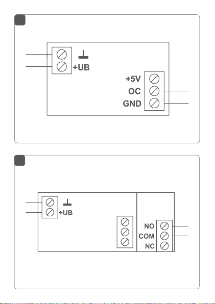
5.2 Anschlussbelegung
5.2.1 Konfiguration mit Open-Collector-Ausgang:
s. Abbildung 2
5.2.2 Konfiguration mit Relais-Schaltausgang:
s. Abbildung 3
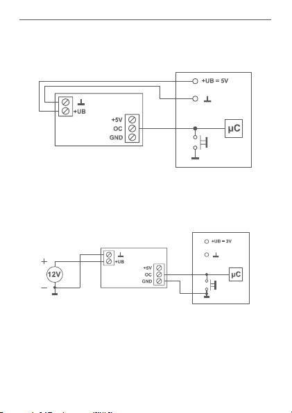
5.3 Anschlussbeispiele
Die Platine kann in einem Betriebsspannungsbereich von
5 bis 25 V betrieben werden.
Alternativ zum direkten Schalten von Lasten durch das
Miniatur-Relais kann die Platine das Relais-Schaltmodul
RSM1 ansteuern, wenn das Schalten größerer Lasten erforderlich ist. Das Ansteuern anderer externer Leistungsrelais ist ebenfalls möglich.
Die Anschlussbeispiele auf den folgenden Seiten zeigen
typische Anwendungen der Platine.
12
Page 13
Inbetriebnahme
(1) Ansteuerung eines Schalteingangs (hier einer Mikroprozessor-
schaltung) und Spannungsversorgung aus dieser Schaltung:
(2) Ansteuerung eines Schalteingangs (hier einer Mikroprozes-
sorschaltung) und Spannungsversorgung aus eigener Spannungsquelle:
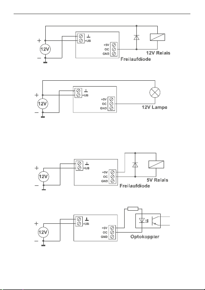
(3) Ansteuerung eines externen Relais (mit Freilaufdiode) oder ei-
ner Lampenlast bis 0,5 A mit Last-Stromversorgung aus der
Eingangsspannung:
13
Page 14
Inbetriebnahme
(4) Ansteuerung eines externen 5 V-Relais (mit Freilaufdiode) oder
eines Optokopplers bzw. einer LED (Vorwiderstand je nach
Bauelement):
14
Page 15

Inbetriebnahme
(5) Ansteuerung des Relaismoduls RSM1 mit Versorgung des Re-
laismoduls aus der Aktor-Betriebsspannung:
(6) Ansteuerung des Relaismoduls RSM1 mit eigenständiger Ver-
sorgung des Relaismoduls:
(7) Ansteuerung einer Last (max. 0,5 A) mit direkter Versorgung
aus der Aktor-Betriebsspannung:
15
Page 16

Inbetriebnahme
5.4 Anlernen
Bitte lesen Sie diesen Abschnitt erst vollständig,
bevor Sie mit dem Anlernen beginnen.
Richten Sie zunächst Ihren Homematic IP Access
Point über die Homematic IP App ein, um weitere
Homematic IP Geräte im System nutzen zu können. Ausführliche Informationen dazu finden Sie
in der Bedienungsanleitung des Access Points.
Sie können das Gerät sowohl an den Access Point
als auch an die Homematic Zentrale CCU2 anler
nen. Weitere Informationen dazu entnehmen Sie
bitte dem Homematic IP Anwenderhandbuch (zu
finden im Downloadbereich unter www.eQ-3.de).
Damit die Schaltplatine in Ihr System integriert werden
und mit anderen Homematic IP Geräten kommunizieren
kann, muss die Platine zunächst an den Homematic IP
Access Point angelernt werden.
Zum Anlernen der Platine gehen Sie wie folgt vor:
• Önen Sie die Homematic IP App auf Ihrem
Smartphone.
• Wählen Sie den Menüpunkt „Gerät anlernen“ aus.
• Nach dem Anschließen der Platine an die Versorgungsspannung ist der Anlernmodus für 3 Minuten aktiv.
16
-
Page 17

Inbetriebnahme
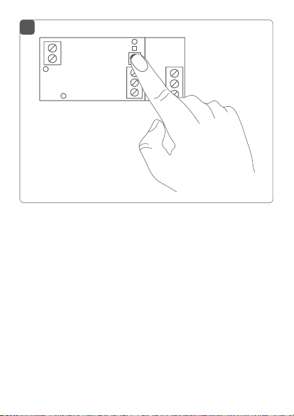
Sie können den Anlernmodus manuell für weitere
3 Minuten starten, indem Sie die Systemtaste (B)
kurz drücken (s. Abbildung 4).
• Das Gerät erscheint automatisch in der Homematic IP App.
• Zur Bestätigung geben Sie in der App die letzten
vier Ziern der Gerätenummer (SGTIN) ein oder
scannen Sie den QR-Code. Die Gerätenummer
finden Sie auf dem Aufkleber im Lieferumfang
oder direkt am Gerät.
• Warten Sie, bis der Anlernvorgang abgeschlossen
ist.
• Zur Bestätigung eines erfolgreichen Anlernvorgangs leuchtet die Geräte-LED (A) grün. Das Gerät ist nun einsatzbereit.
• Leuchtet die Geräte-LED rot, versuchen Sie es
erneut.
• Wählen Sie aus, in welcher Anwendung (z. B.
Licht oder Sicherheit) Sie Ihr Gerät verwenden
möchten.
• Ordnen Sie das Gerät in der App einem Raum zu
und vergeben Sie einen Namen für das Gerät.
17
Page 18

Bedienung
6 Bedienung
Nach dem Anlernen können Sie die Schaltplatine z. B. mit
einer angelernten Homematic IP Fernbedienung oder
über die Homematic IP App steuern und so angeschlos
sene Verbraucher ein- oder ausschalten.
Einfache Bedienfunktionen stehen auch direkt am Gerät
zur Verfügung:
• Um einen Funktionstest durchzuführen oder den
Aktor ein- bzw. auszuschalten, drücken Sie kurz
auf die Systemtaste
nalisiert dabei den Schaltzustand. Ist der Aktor
eingeschaltet, leuchtet die Geräte-LED dauerhaft.
(B)
. Die Geräte-LED
(A)
-
sig-
7 Fehlerbehebung
7.1 Befehl nicht bestätigt
Bestätigt mindestens ein Empfänger einen Befehl nicht,
leuchtet zum Abschluss der fehlerhaften Übertragung
die LED (A) rot auf. Grund für die fehlerhafte Übertragung
kann eine Funkstörung sein (s. „1 Hinweise zur Anleitung“
auf Seite 7). Die fehlerhafte Übertragung kann folgende Ursachen haben:
• Empfänger nicht erreichbar,
• Empfänger kann Befehl nicht ausführen (Lastausfall, mechanische Blockade etc.) oder
• Empfänger defekt.
18
Page 19

Fehlerbehebung
7.2 Duty Cycle
Der Duty Cycle beschreibt eine gesetzlich geregelte Begrenzung der Sendezeit von Geräten im 868 MHz-Bereich. Das Ziel dieser Regelung ist es, die Funktion aller im
868-MHz-Bereich arbeitenden Geräte zu gewährleisten.
In dem von uns genutzten Frequenzbereich 868 MHz be
trägt die maximale Sendezeit eines jeden Gerätes 1 % einer Stunde (also 36 Sekunden in einer Stunde). Die Geräte
dürfen bei Erreichen des 1 %-Limits nicht mehr senden,
bis diese zeitliche Begrenzung vorüber ist. Gemäß dieser
Richtlinie, werden Homematic IP Geräte zu 100 % normen
konform entwickelt und produziert. Im normalen Betrieb
wird der Duty Cycle in der Regel nicht erreicht. Dies kann
jedoch in Einzelfällen bei der Inbetriebnahme oder Erstins
tallation eines Systems durch vermehrte und funkintensive
Anlernprozesse der Fall sein. Eine Überschreitung des Duty
Cycle-Limits wird durch dreimal langes rotes Blinken der
Geräte-LED
fehlende Funktion des Gerätes äußern. Nach kurzer Zeit
(max. 1 Stunde) ist die Funktion des Gerätes wiederherge
stellt.
(A)
angezeigt und kann sich durch temporär
19
-
-
-
-
Page 20

Fehlerbehebung
7.3 Fehlercodes und Blinkfolgen
Blinkcode Bedeutung Lösung
Kurzes
oranges
Blinken
1x langes
grünes
Leuchten
1x langes
rotes
Leuchten
Kurzes
oranges
Blinken
(alle 10 s)
1x langes
rotes
Leuchten
20
Funkübertragung/Sendeversuch/
Datenübertragung
Vorgang
bestätigt
Vorgang
fehlgeschlagen
Anlernmodus
aktiv
Vorgang
fehlgeschlagen oder
Duty CycleLimit erreicht
Warten Sie, bis die
Übertragung beendet
ist.
Sie können mit der
Bedienung fortfahren.
Versuchen Sie es erneut
(s. „7.1 Befehl nicht bestätigt“ auf Seite 18).
Geben Sie die letzten
vier Ziern der GeräteSeriennummer zur
Bestätigung ein (s. „5.4
Anlernen“ auf Seite
16).
Versuchen Sie es erneut („7.1 Befehl nicht
bestätigt“ auf Seite
18 oder „7.2 Duty
Cycle“ auf Seite 19).
Page 21

Wiederherstellung der Werkseinstellungen
6x langes
rotes Blinken
1x oranges
und 1x grünes
Leuchten
(nach dem
Anlegen der
Versorgungsspannung)
Gerät defekt Achten Sie auf die
Anzeige in Ihrer App
oder wenden Sie sich an
Ihren Fachhändler.
Testanzeige Nachdem die Testan-
zeige erloschen ist,
können Sie fortfahren.
8 Wiederherstellung der
Werkseinstellungen
Die Werkseinstellungen des Gerätes können wiederhergestellt werden. Dabei gehen alle Einstellungen verloren.
Um die Werkseinstellungen der Schaltplatine wiederherzustellen, gehen Sie wie folgt vor:
• Trennen Sie die Schaltplatine von der Versorgungsspannung.
• Verbinden Sie die Platine bei gedrückter Systemtaste (B) wieder mit der Versorgungsspannung
und halten Sie die Systemtaste für 4 s gedrückt
(s. Abbildung 4), bis die LED (A) schnell orange zu
21
Page 22

Allgemeine Hinweise zum Funkbetrieb
blinken beginnt.
• Lassen Sie die Systemtaste wieder los.
• Drücken Sie die Systemtaste erneut für 4 s, bis die
LED grün aufleuchtet.
• Lassen Sie die Systemtaste wieder los, um das
Wiederherstellen der Werkseinstellungen abzuschließen.
Das Gerät führt einen Neustart durch.
9 Allgemeine Hinweise zum
Funkbetrieb
Die Funk-Übertragung wird auf einem nicht exklusiven
Übertragungsweg realisiert, weshalb Störungen nicht
ausgeschlossen werden können. Weitere Störeinflüsse
können hervorgerufen werden durch Schaltvorgänge,
Elektromotoren oder defekte Elektrogeräte.
Die Reichweite in Gebäuden kann stark von der
im Freifeld abweichen. Außer der Sendeleistung
und den Empfangseigenschaften der Empfänger
spielen Umwelteinflüsse wie Luftfeuchtigkeit
neben baulichen Gegebenheiten vor Ort eine
wichtige Rolle.
Hiermit erklärt die eQ-3 AG, dass sich dieses Gerät in
Übereinstimmung mit den grundlegenden Anforderun-
22
Page 23

Technische Daten
gen und den anderen relevanten Vorschriften der Richtlinie 1999/5/EG befindet. Die vollständige Konformitätserklärung finden Sie unter www.eQ-3.de.
10 Technische Daten
Geräte-Kurzbezeichnung:
Versorgungsspannung: 5 bis 25 VDC
Stromaufnahme ohne Relais: 50mA max.
Stromaufnahme mit Relais: 70 mA max.
Relais:
Lastart: ohmsche Last
Maximale Schaltspannung: 30 V
Maximaler Schaltstrom: 1 A
Transistor-Schaltausgang: Open-collector
Maximaler Schaltstrom: 0,5 A
Leitungsart u. -querschnitt: starre und flexible Leitung,
Umgebungstemperatur: -10 bis +35 °C
Schutzklasse: III
Verschmutzungsgrad: 2
Abmessungen (B x H x T): 28 x 48 x 21 mm
Gewicht: 13 g
Funkfrequenz: 868,3 MHz/869,525 MHz
Empfängerkategorie: SRD category 2
Typ. Funk-Freifeldreichweite: 350 m
Duty Cycle: < 1 % pro h/< 10 % pro h
HmIP-PCBS
Wechsler, 1-polig, -Kontakt
0,75-1,0 mm²
(mit Relais)
23
Page 24

Technische Daten
Technische Änderungen vorbehalten.
Entsorgungshinweis
Gerät nicht im Hausmüll entsorgen! Elektronische Geräte sind entsprechend der Richtlinie
über Elektro- und Elektronik-Altgeräte über die
örtlichen Sammelstellen für Elektronik-Altgeräte
zu entsorgen.
Konformitätshinweis
Das CE-Zeichen ist ein Freiverkehrszeichen, das
sich ausschließlich an die Behörden wendet und
keine Zusicherung von Eigenschaften beinhaltet.
Bei technischen Fragen zum Gerät wenden Sie
sich bitte an Ihren Fachhändler.
24
Page 25

Technische Daten
Package contents
Quantity Description
1 Switch Circuit Board
1 Operating manual
Documentation © 2017 eQ-3 AG, Germany.
All rights reserved. Translation from the original version in German. This manual may not be reproduced in any format, either in
whole or in part, nor may it be duplicated or edited by electronic,
mechanical or chemical means, without the written consent of
the publisher.
Typographical and printing errors cannot be excluded. However,
the information contained in this manual is reviewed on a regular
basis and any necessary corrections will be implemented in the
next edition. We accept no liability for technical or typographical
errors or the consequences thereof.
All trademarks and industrial property rights are acknowledged.
Printed in Hong Kong
Changes may be made without prior notice as a result of technical advances.
150437
Version 1.0 (01/2017)
25
Page 26

Table of contents
1 Information about this manual....................................27
2 Hazard information ........................................................27
3 Function and device overview ................................... 30
4 General system information ........................................ 31
5 Start-up ............................................................................ 31
5.1 Installation .............................................................................31
5.2 Connection assignment .................................................... 32
5.2.1 Configuration of the open collector output: ... 32
5.2.2 Configuration with relay switching output: ..... 32
5.3 Connection examples........................................................ 32
5.4 Teaching-in .......................................................................... 36
6 Operation .........................................................................37
7 Troubleshooting .............................................................38
7.1 Command not confirmed ................................................. 38
7.2 Duty cycle ........................................................................... 39
7.3 Error codes and flashing sequences .............................. 40
8 Restore factory settings ................................................ 41
9 General information about radio operation .............42
10 Technical specifications ................................................43
26
Page 27

Information about this manual
1 Information about this manual
Please read this manual carefully before beginning operation with your Homematic IP components. Keep the
manual so you can refer to it at a later date if you need to.
If you hand over the device to other persons for use,
please hand over this manual as well.
Symbols used:
Attention!
This indicates a hazard.
Please note:
This section contains important additional information.
2 Hazard information
To ensure adequate protection against electrostatic discharge, the device must be installed inside a suitable housing so that there is no risk of
the circuit being damaged by contact with fingers
or objects.
The device does not contain any parts that can be
maintained by the user. In the event of an error,
please have the device checked by an expert.
27
Page 28

Hazard information
For safety and licensing reasons (CE),
unauthorized change and/or modification of the
device is not permitted.
The device may only be operated in dry and dustfree environment and must be protected from
the eects of moisture, vibrations, solar or other
methods of heat radiation, cold and mechanical
loads.
The device is not a toy; do not allow children to
play with it. Do not leave packaging material lying
around. Plastic films/bags, pieces of polystyrene,
etc. can be dangerous in the hands of a child.
Do not use the device if there are signs of damage
to the housing, control elements or connecting
sockets, for example, or if it demonstrates a
malfunction. If you have any doubts, have the
device checked by an expert.
We do not assume any liability for damage to
property or personal injury caused by improper
use or the failure to observe the hazard
information. In such cases, any claim under
warranty is extinguished! For consequential
damages, we assume no liability!
28
Page 29

Hazard information
All load data relates to ohmic loads! Do not
exceed the capacity specified for the device.
Exceeding this capacity could lead to the
destruction of the device, to a fire or to an
electrical accident. Provide fuse protection to the
switching outputs (relays, transistor)!
In order to ensure that the equipment is electrically safe, the feeding source must be a safety
extra-low voltage.
The connected cables must not exceed a length
of 50 cm. The power supply cables may be run
only in dry indoor rooms.
Using the device for any purpose other than that
described in this operating manual does not fall
within the scope of intended use and shall
invalidate any warranty or liability. This also
applies to any conversion or modification work.
The device does not require you to carry out any
maintenance. Enlist the help of an expert to carry
out any maintenance or repairs.
The device may only be operated within residential buildings.
29
Page 30

Function and device overview
3 Function and device overview
The Homematic IP Switch Circuit Board oers wireless
switching of e.g. a switch or push-button input, 12 V signalling device or LEDs in the extra-low voltage range.
The PCB is intended for operation with permanent power
supply.
The switching output of the PCB oers the following application possibilities:
The device has a miniature relay with a switching capacity
of up to 30 V/1 A.
If this is not required, you can simply break o the corresponding part from the module and use the open collector switching output instead. The open collector switching output enables switching of loads with a switching
voltage of up to 30 V and a switching current of up to 0.5
A. It can be used for switching of external relays and loads
and for controlling electronic circuits.
Device overview (see figure 1):
(A) Device LED
(B) System button
(C) Operating voltage
(D) Fixing holes
(E) Open collector switching output
(F) Relay switching output
30
Page 31

General system information
4 General system information
This device is part of the Homematic IP smart home
system and works with the Homematic IP radio
protocol. All devices of the system can be configured
comfortably and individually with the Homematic IP
smartphone app. Alternatively, you can operate the
Homematic IP devices via the Homematic Central
Control Unit CCU2 or in connection with various
partner solutions. The available functions provided by
the system in combination with other components are
described in the Homematic IP User Guide. All current
technical documents and updates are provided at
www.eQ-3.de.
5 Start-up
5.1 Installation
Please read this entire section before starting to
install the device.
The PCB is a built-in module and can be easily retrofitted into you own installations using the fixing holes (D).
Please observe the information in sec. „2 Hazard information“ on page 27 when installing it into a housing. Also
observe the following permitted wire cross-section for
connecting to the switch circuit board.
31
Page 32

Start-up
rigid cable [mm2] flexible cable with/without ferrule
0.75 – 1.0 0.75 – 1.0
[mm2]
5.2 Connection assignment
5.2.1 Configuration of the open collector output:
see fig. 2
5.2.2 Configuration with relay switching output:
see fig. 3
5.3 Connection examples
The PCB can be operated in an operating voltage range
between 5 to 25 V.
As an alternative to direct switching of loads by the miniature relay, the PCB can control the relay switching module RSM1, if switching of higher loads is required. Controlling of other external power relays is possible as well.
The connection examples on the following pages show
typical applications of the PCB:
32
Page 33

Start-up
(1) Controlling a switch input (in this case a microprocessor con-
troller) and power supplied by this circuit:
(2) Controlling a switch input (in this case a microprocessor con-
troller) and power supplied by own power source:
(3) Controlling an external relay (with free-wheeling diode) or a
lamp load of up to 0.5 A with load supplied by the input voltage:
33
Page 34

Start-up
(4) Controlling an external 5 V relay (with free-wheeling diode)
or an optocoupler or LED (series resistor according to the
component):
34
Page 35

Start-up
(5) Controlling the relay module RSM1 with power supplied for
the relay module by the operating voltage of the actuator:
(6) Controlling the relay module RSM1 with independent power
supply of the relay module:
(7) Controlling of a load (0.5 A max.) with power supplied directly
by the operating voltage of the acutator:
35
Page 36

Start-up
5.4 Teaching-in
Please read this entire section before starting
the teach-in procedure.
First set up your Homematic IP Access Point via
the Homematic IP app to enable operation of
other Homematic IP devices within your system.
For further information, please refer to the operating manual of the Access Point.
You can connect the device either to the Access
Point or to the Homematic Central Control Unit
CCU2. For detailed information, please refer to
the Homematic IP User Guide, available for down
load in the download area of www.eQ-3.de.
To integrate the switch circuit board into your system and
enable it to communicate with other Homematic IP devices, you must teach-in the device to your Homematic
IP Access Point first.
To teach-in the switch circuit board, please proceed as
follows:
• Open the Homematic IP app on your smartphone.
• Select the menu item “Teach-in device”.
• After connecting the PCB to the power supply,
the teach-in mode remains activated for 3 minutes.
36
-
Page 37

Operation
You can manually start the teach-in mode for another 3 minutes by pressing the system button (B)
shortly (see figure 4).
• Your device will automatically appear in the
Homematic IP app.
• To confirm, please enter the last four digits of the
device number (SGTIN) in your app or scan the
QR code. Therefore, please see the sticker supplied or attached to the device.
• Please wait until teach-in is completed.
• If teaching-in was successful, the device LED (A)
lights up green. The device is now ready for use.
• If the device LED lights up red, please try again.
• Please select, in which application (e.g. light or
security) you would like to use the device.
• Allocate the device to a room and give the device
a name.
6 Operation
After teaching-in, you can control the switch circuit board
e.g. using a connected Homematic IP Remote Control or
the Homematic IP app and switch connected devices on
or o.
Simple operating functions are available also directly on
the device:
37
Page 38

Troubleshooting
• To trigger a function test or to switch the actuator
on of o, press the system button
device LED
device LED lights up permanently as soon as the
actuator is switched on.
(A)
indicates the switching state. The
(B)
shortly. The
7 Troubleshooting
7.1 Command not confirmed
If at least one receiver does not confirm a command, the
device LED (A) lights up red at the end of the failed transmission process. The failed transmission may be caused
by radio interference (see „1 Information about this manual“ on page 27). This may be caused be the following:
• Receiver cannot be reached.
• Receiver is unable to execute the command (load
failure, mechanical blockade, etc.).
• Receiver is defective.
38
Page 39

Troubleshooting
7.2 Duty cycle
The duty cycle is a legally regulated limit of the transmission time of devices in the 868 MHz range. The aim of
this regulation is to safeguard the operation of all devices
working in the 868 MHz range.
In the 868 MHz frequency range we use, the maximum
transmission time of any device is 1% of an hour (i.e. 36
seconds in an hour). Devices must cease transmission
when they reach the 1% limit until this time restriction
comes to an end. Homematic IP devices are designed and
produced with 100% conformity to this regulation. During
normal operation, the duty cycle is not usually reached.
However, repeated and radio-intensive teach-in pro
cesses mean that it may be reached in isolated instances
during start-up or initial installation of a system. If the duty
cycle is exceeded, this is indicated by three long flashes of
(A)
the device LED
, and may manifest itself in the device
temporarily working incorrectly. The device starts working
correctly again after a short period (max. 1 hour).
-
39
Page 40

Troubleshooting
7.3 Error codes and flashing sequences
Flashing
code
Short orange
flashing
1x long green
lighting
1x long red
lighting
Short orange
flashing
(every 10 s)
1x long red
lighting
40
Meaning Solution
Radio
transmission/
Wait until the transmis-
sion is completed.
attempting to
transmit/data
transmission
Transmission
confirmed
Transmission
failed
You can continue
operation.
Please try again (s. „7.1
Command not con-
firmed“ on page 38).
Teach-in
mode active
Please enter the last
four numbers of the
device serial number
to confirm (see „5.4
Teaching-in“ on page
36).
Transmission
failed or duty
cycle limit is
reached
Please try again (see
sec. „7.1 Command not
confirmed“ on page
38 or „7.2 Duty cy-
cle“ on page 39).
Page 41

Restore factory settings
6x long red
flashing
1x orange
and 1 x green
lighting (after
power supply
is applied)
Device defective
Test display Once the test display
Please see your app
for error message or
contact your retailer.
has stopped, you can
continue.
8 Restore factory settings
The factory settings of the device can be restored.
If you do this, you will lose all your settings.
To restore the factory settings of the switch circuit board,
please proceed as follows:
• Disconnect the switch circuit board from the
power supply.
• Restore the power supply of the PCB while pressing the system button (B) and hold down the system button for 4 seconds (see fig. 4) until the LED
(A) will quickly start flashing orange.
• Release the system button again.
• Press and hold down the system button again for
4 seconds, until the status LED lights up green.
• Release the system button to finish the procedure.
The device will perform a restart.
41
Page 42

General information about radio operation
9 General information about radio
operation
Radio transmission is performed on a non-exclusive
transmission path, which means that there is a possibility of interference occurring. Interference can also be
caused by switching operations, electrical motors or defective electrical devices.
The range of transmission within buildings can
dier greatly from that available in the open air.
Besides the transmitting power and the reception
characteristics of the receiver, environmental
factors such as humidity in the vicinity have an
important role to play, as do on-site structural/
screening conditions.
eQ-3 AG hereby declares that this device complies with
the essential requirements and other relevant regulations
of Directive 1999/5/EC. You can find the full declaration
of conformity at www.eQ-3.de.
42
Page 43

Technical specifications
10 Technical specifications
Device short description:
Supply voltage: 5 to 25 VDC
Current consumption without relay:
Current consumption with relay:
Relay: changeover contact,
Kind of load: ohmic load
Switching voltage (max.): 30 V
Switching current (max.): 1 A
Transistor switching output: open-collector
Switching voltage (max.): 30 V
Switching current (max.): 0.5 A
Cable type and cross section: rigid and flexible cable,
Ambient temperature: -10 to +35 °C
Protection class: III
Pollution degree: 2
Dimensions (W x H x D): 28 x 48 x 21 mm
Weight: 13 g
Radio frequency: 868.3 MHz/869.525 MHz
Receiver category: SRD category 2
Typ. open area RF range: 350 m
Duty cycle: < 1 % per h/< 10 % per h
Subject to technical changes.
HmIP-PCBS
50mA max.
70 mA max.
1-pole, µ contact
0.75-1.0 mm²
(incl. relay)
43
Page 44

Technical specifications
Instructions for disposal
Do not dispose of the device with regular
domestic waste! Electronic equipment must be
disposed of at local collection points for waste
electronic equipment in compliance with the
Waste Electrical and Electronic Equipment
Directive.
Information about conformity
The CE sign is a free trading sign addressed exclusively to the authorities and does not include
any warranty of any properties.
For technical support, please contact your retailer.
44
Page 45

Kostenloser Download der Homematic IP App!
Free download of the Homematic IP app!
Bevollmächtigter des Herstellers:
Manufacturer’s authorised representative:
eQ-3 AG
Maiburger Straße 29
26789 Leer / GERMANY
www.eQ-3.de
 Loading...