

Page 1
Istruzioni per l’uso
Operating manual
Bedienungsanleitung
Presa di commutazione-misurazione
Pluggable Switch and Meter p. 24
Schalt-Mess-Steckdose p. 42
HmIP-PSM-IT
S. 2
Page 2

Volume di fornitura
Quantità Definizione
1 Presa di commutazione-misurazione
1 Istruzioni per l’uso
Documentazione © 2016 eQ-3 AG, Germania
Tutti i diritti riservati. È vietata la riproduzione di questo manuale
o di sue parti in qualsiasi forma o la sua duplicazione o modifica
con l’utilizzo di processi elettronici, meccanici o chimici senza la
previa approvazione scritta da parte del produttore.
Non si escludono imperfezioni dovute alla tecnica di stampa o
errori di stampa in questo manuale. Le informazioni qui contenute
sono comunque costantemente verificate e le eventuali correzioni sono rese note nell'edizione successiva. Si declina qualsiasi
responsabilità per errori di tipo tecnico o di stampa e per le loro
conseguenze.
Sono riconosciuti tutti i marchi depositati e i diritti d'autore.
Stampato ad Hong Kong.
Possono aver luogo modifiche ai sensi dello sviluppo tecnico e
senza preavviso.
150027 (web)
Versione 1.0 (08/2016)
Homematic IP
Page 3
1
A
Page 4
2
Page 5
3
Page 6

Indice
1 Note su queste istruzioni ................................................ 7
2 Indicazioni sui pericoli .................................................... 7
3 Funzione e vista d’insieme dell’apparecchio ............ 11
4 Informazioni generali sul sistema ............................... 11
5 Messa in funzione .......................................................... 12
5.1 Montaggio e autoapprendimento ....................................12
6 Modalità d’uso .................................................................14
7 Comportamento dopo il ritorno della tensione ...... 15
8 Eliminazione dei guasti ................................................. 15
8.1 Comando non confermato ...............................................15
8.2 Duty Cycle ............................................................................16
8.3 Codici di errore e sequenze di lampeggio .....................17
9 Ripristino delle impostazioni di fabbrica ...................18
10 Manutenzione e pulizia .................................................19
11 Informazioni generali sul servizio radio.....................19
12 Dati tecnici .......................................................................21
6
Page 7
Note su queste istruzioni
1 Note su queste istruzioni
Leggere attentamente queste istruzioni prima di mettere in funzione i componenti Homematic IP. Conservare
questo manuale per future consultazioni! Se si ada l’utilizzo dell’apparecchio ad altre persone si prega di consegnare anche queste istruzioni per l’uso.
Simboli impiegati:
Attenzione!
Qui è segnalato un pericolo.
Nota.
Questo paragrafo contiene altre informazioni importanti!
2 Indicazioni sui pericoli
Per danni materiali o corporali, causati da un utilizzo improprio o dalla mancata osservanza delle indicazioni sui pericoli, non assumiamo alcuna responsabilità
rivendicazione di garanzia! Per danni indiretti non
assumiamo alcuna responsabilità!
Non aprire mai l’apparecchio: non contiene parti
che possono essere riparate. L’apertura
dell’apparecchio comporta il pericolo di una
scossa elettrica. In caso di anomalia far controllare
.
In suddetti casi si estingue ogni
7
Page 8
Indicazioni sui pericoli
l’apparecchio da un tecnico specializzato.
Non utilizzare l’apparecchio se dall’esterno siano
riconoscibili danni, ad esempio sulla scatola, su
elementi di controllo o sulle prese o vi sia un gua
sto funzionale. In caso di dubbio far controllare
l’apparecchio da un tecnico specializzato.
Per ragioni di sicurezza o di omologazione (CE)
non sono ammesse modifiche costruttive o di altro genere del prodotto.
Impiegare l’apparecchio solo in ambienti interni e
non esporlo a umidità, a vibrazioni, a irradiazioni
solari permanenti o ad altre fonti di calore, al fred
do e a sollecitazioni meccaniche.
L’apparecchio non è un giocattolo, evitare pertanto che bambini ne facciano un tale uso. Non lasciare incustoditi il materiale di imballaggio, le pellicole/i sacchetti di plastica, le parti di polistirolo,
ecc., potrebbero diventare un pericoloso giocattolo per i bambini.
Prima del collegamento di un’utenza fare
attenzione ai dati tecnici, in particolare alla
potenza d’interruzione massima ammessa del relè
e al tipo di utenza da collegare! Tutte le indicazioni
8
-
-
Page 9
Indicazioni sui pericoli
di carico si riferiscono a carichi ohmici! Caricare
l’apparecchio solo fino al limite della capacità
indicato. Un sovraccarico può comportare la sua
distruzione, un incendio o un infortunio elettrico.
L’apparecchio deve essere collegato solo a una
presa di rete facilmente accessibile In caso di pericolo l’apparecchio va staccato dalla presa di rete.
Impiegare l’apparecchio solo in prese di rete fisse
con contatti di protezione, non in prese multiple o
cavi di prolunga.
Non collegare alcun apparecchio terminale alla
presa di commutazione e misurazione, l’accensione non sorvegliata dei quali potrebbe causare incendi o altri danni (ad es. ferro da stiro).
Di norma staccare la spina dell’apparecchio terminale dalla presa di commutazione-misurazione prima
di apportare delle modifiche all’apparecchio stesso.
Posare i cavi in modo tale che non provochino situazioni di pericolo per le persone e gli animali
domestici.
L’apparecchio non è idoneo all’attivazione. Il carico non è scollegato dalla rete in modo galvanico.
9
Page 10
Indicazioni sui pericoli
Nell’impiego in un’applicazione di sicurezza l’apparecchio va utilizzato in collegamento con una
UPS (alimentazione di corrente senza interruzioni)
al fine di bypassare un’eventuale interruzione
dell’energia elettrica come da EN 50130-4.
Qualsiasi altro impiego non descritto nelle presenti istruzioni per l’uso non è conforme alle disposizioni e comporta l’esclusione della responsabilità e
la perdita dei diritti di garanzia. Questo vale anche
per ricostruzioni e modifiche. L’apparecchio è sta
to concepito solo per uso privato.
Apparecchi con spine intermedie non devono essere inseriti uno dopo l’altro.
Apparecchi con alimentatori elettronici (ad esempio televisori o lampadine a LED ad alto voltaggio)
non configurano alcun carico ohmico. Essi possono determinare correnti di transitorio superiori a
100 A. L’inserimento di tali utenze comporta una
prematura usura dell’attuatore.
L’apparecchio è adatto solo all’impiego in ambienti abitativi o analoghi.
10
-
Page 11

Funzione e vista d’insieme dell’apparecchio
3 Funzione e vista d’insieme
dell’apparecchio
Con la presa di commutazione-misurazione Homematic
IP è possibile accendere e spegnere comodamente utenze collegate e misurare il consumo energetico, nonché
la tensione, la corrente e la potenza di questi apparecchi.
Mediante l’app di Homematic IP è possibile farsi visualizzare il consumo energetico delle utenze collegate e
calcolare i relativi costi (€/kWh).
La presa di commutazione-misurazione può essere
montata velocemente e senza alcun utensile - una volta innestato alla presa l’apparecchio è subito pronto per
la messa in funzione. Grazie alla struttura compatta non
blocca alcuna presa che si trovi nelle vicinanze.
In via opzionale può essere usata anche come router per
prolungare il raggio d‘onda.
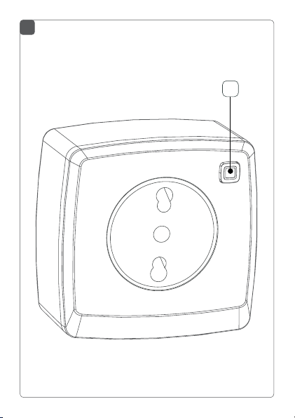
Vista d’insieme degli apparecchi (v. immagine 1):
(A) Tasto di sistema (autoapprendimento, accensione
e spegnimento delle utenze e LED collegati LED)
4 Informazioni generali sul sistema
Questo apparecchio è parte del sistema Smart-Home
Homematic IP e comunica mediante il protocollo radio
HmIP. Tutti gli apparecchi Homematic IP possono es-
11
Page 12

Messa in funzione
sere configurati in modo confortevole e individuale via
smartphone tramite l’app Homematic IP. Quale gamma di funzioni si possa realizzare all’interno del sistema
Homematic IP nell’abbinamento con altri componenti
è riportato nel relativo manuale d’impiego. Tutti i documenti tecnici e gli update sono sempre attualizzati al sito
www.eQ-3.de.
5 Messa in funzione
5.1 Montaggio e autoapprendimento
Si prega di leggere interamente questo paragrafo prima di iniziare con l’autoapprendimento
programmazione.
Predisporre dapprima l’Homematic IP Access
Point tramite app Homematic IP, per poter utilizzare altri apparecchi nel sistema Homematic IP.
Informazioni dettagliate sono riportate nelle
istruzioni per l’uso dell’Access Point.
Per fare in modo che la presa di commutazione-misurazione possa essere integrata nel vostro sistema e comunicare con altri parecchi Homematic IP, dapprima deve
essere associata allo Homematic IP Access Point.
Per l’autoapprendimento della presa di commutazione-misurazione procedere nel modo seguente:
12
Page 13

Messa in funzione
• aprire l’app Homematic IP sullo smartphone.
• Selezionare il punto di menù “Apprendimento
apparecchio”.
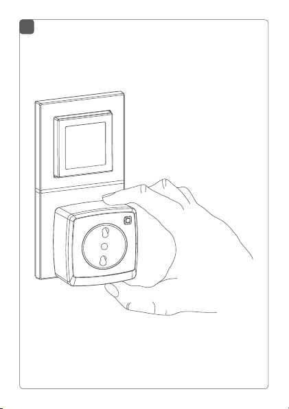
• Inserire la presa di commutazione-misurazione
nella presa desiderata (v. immagine 2).
• La modalità di apprendimento è attiva per tre minuti.
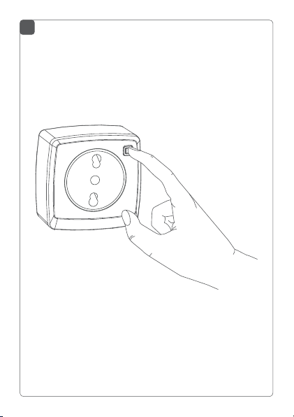
È possibile avviare la modalità di apprendimento
manualmente per altri 3 minuti premendo brevemente il tasto di sistema (A) (v. immagine 3).
• L’apparecchio appare automaticamente nell’app
Homematic IP.
• Per confermare inserire nell’app le ultime quattro cifre del numero dell’apparecchio (SGTIN) o
eseguire una scansione del codice QR. Il numero
dell’apparecchio è riportato nell’etichetta adesiva
compresa nella fornitura o direttamente sull’apparecchio.
• Attendere che la procedura di autoapprendimento sia conclusa.
• A conferma dell’avvenuto autoapprendimento il
LED invia una luce verde. L’apparecchio è pronto
per essere impiegato.
• Se il LED invia una luce rossa, riprovare.
• Scegliere la soluzione desiderata per il proprio
apparecchio.
13
Page 14

Modalità d’uso
• Nella app assegnare un nome all’apparecchio e
associarlo a un locale.
Una volta eseguito procedura di autoapprendimento è
possibile collegare utenze alla presa di commutazione e
misurazione, accendere e spegnere e misurare il consumo energetico.
6 Modalità d’uso
Dopo l’autoapprendimento e l’inserimento nella presa,
direttamente sull’apparecchio sono disponibili semplici
funzioni d’impiego:
• premere brevemente il tasto di sistema (A) per
spegnere o accendere utenze collegate.
Un impiego non corretto o un’installazione sul
posto non intatta (ad es. spine o prese scadenti o
difettose) possono causare un surriscaldamento
della presa di commutazione e di misurazione. Il
monitoraggio integrato della temperatura
dell’apparecchio assicura la disattivazione del carico. Questo protegge da surriscaldamento e assicura un funzionamento sicuro. Non appena la
temperatura ha nuovamente raggiunto un valore
non critico, è possibile attivare di nuovo la presa
di commutazione e di misurazione. Fare in ogni
caso attenzione alla temperatura ambientale
dell’apparecchio e se necessario fare eseguire da
14
Page 15

Comportamento dopo il ritorno della tensione
una persona specializzata un controllo di eventuali fonti
di anomalie.
7 Comportamento dopo il ritorno
della tensione
Dopo aver inserito l’apparecchio in una presa o dopo il ritorno della tensione di retela presa di commutazione e di
misurazione
LED lampeggia brevemente in arancio e verde (indicazione di testo LED).
viene ragurato dal lampeggiare del LED (v. “8.3 Codici di
errore e sequenze di lampeggio” a pagina 17). In caso di
un errore questa procedura si ripete e l’apparecchio inizia
di nuovo la sua funzione. Se il test è eseguito senza rilevare
errori, la presa di commutazione e di misurazione invia un
telegramma via radio con la sua informazione di stato.
esegue un autotest/riavvio (ca. 2 secondi). Il
Nel caso si accerti un errore lo stesso
8 Eliminazione dei guasti
8.1 Comando non confermato
Se almeno un ricevitore non conferma un comando, alla
fine della trasmissione difettosa il LED invia una luce rossa. Il motivo della trasmissione difettosa può essere un
disturbo radio (v. “11 Informazioni generali sul servizio radio” a pagina 20). La trasmissione difettosa può avere
queste cause:
• ricevitore non raggiungibile
15
Page 16

Eliminazione dei guasti
• ricevitore non può eseguire ordine (interruzione
di carico, blocco meccanico, ecc.)
• Ricevitore difettoso
8.2 Duty Cycle
Il Duty Cycle descrive una limitazione del tempo di trasmissione, regolata per legge, di apparecchi nella gamma
868 MHz. Scopo di questa regolazione è quello di garantire il funzionamento di tutti gli apparecchi nel campo
868 MHz.
Nel campo di frequenza 868 MHz da noi utilizzato il tempo massimo di trasmissione di ogni apparecchio ammonta all’1 % di un’ora (quindi 36 secondi in un’ora). Al raggiungimento del limite di 1 % gli apparecchi non devono
più trasmettere fino a che non è trascorsa la limitazione
di tempo. In conformità a questa direttiva, gli apparecchi Homematic IP vengono sviluppati e prodotti al 100 %
conformi alle norme.
Nel funzionamento normale il Duty Cycle di regola non
viene raggiunto. Questo può tuttavia accadere in casi singoli alla messa in esercizio o alla prima installazione di un
sistema a causa di processi di apprendimento amplificati
o di intensità radio. Un superamento del limite del Duty
Cycle Limits viene visualizzato tre volte da un lampeggio
lungo del LED e può manifestarsi con una funzione momentaneamente assente dell’apparecchio. Dopo breve
tempo (max. 1 secondo) la funzione è ripristinata.
16
Page 17

Eliminazione dei guasti
8.3 Codici di errore e sequenze di lampeggio
Codice di
lampeggio
Breve
lampeggio
arancio (nella
trasmissione
radio)
1x accensione
lunga verde
1x accensione
lunga rossa
Breve
lampeggio
arancio (ogni
10 s)
1x accensione
lunga rossa
Significato Soluzione
Trasmissione
radio/tentativo d'invio/
Attendere che la
trasmissione sia
conclusa.
trasmissione
dati
Procedura
confermata
Ora è possibile pas-
sare alla procedura
successiva.
Procedura
non riuscita
Riprovare (v. “8.1
Comando non confer-
mato” a pagina 15).
Modalità di
apprendimento attiva
Immettere le ultime
quattro cifre del
numero dell'apparec-
chio per confermare
(v. “5.1 Montaggio e
autoapprendimento”
a pagina 12).
Procedura
non riuscita
o raggiunto Duty
Cycle-Limit
Riprovare (v. “8.1 Co-
mando non confer-
mato” a pagina 15
o “8.2 Duty Cycle” a
pagina 16).
17
Page 18
Ripristino delle impostazioni di fabbrica
6x lampeggio
lungo rosso
1x accensione
arancio e 1x
accensione
verde (dopo
l'inserimento
in una presa)
Apparecchio
difettoso
Indicazione
di testo
Prestare attenzione
alla visualizzazione
nella app o rivolgersi
a un rivenditore
specializzato.
Una volta l'indicazio-
ne di testo è spenta è
possibile proseguire.
9 Ripristino delle impostazioni di
fabbrica
Le impostazioni di fabbrica dell’apparecchio possono essere ripristinate. In questo caso tutte le
impostazioni vanno perse.
Per ripristinare le impostazioni di fabbrica della presa di
commutazione e di misurazione procedere nel modo
seguente:
• Staccare la presa di commutazione e di misurazione dalla presa (v. immagine 2).
• Inserire di nuovo la presa di commutazione e di
misurazione nella presa e tenere contemporaneamente premuto il tasto di sistema (A) per 4 s fino
18
Page 19

Manutenzione e pulizia
a che il LED non inizia lampeggiare in arancio (v.
immagine 3).
• Rilasciare quindi il tasto suddetto.
• Premere di nuovo il tasto di sistema per 4 s, fino a
che il LED non invia una luce verde.
• Rilasciare di nuovo il tasto di sistema per ultimare
il ripristino delle impostazioni di fabbrica.
L’apparecchio esegue un riavvio.
10 Manutenzione e pulizia
L’apparecchio non necessita di manutenzione. In
caso si renda necessaria la manutenzione o la riparazione dell’apparecchio, rivolgetevi ad un tecnico specializzato.
Pulirlo solo dopo la rimozione dalla presa con un panno di lino asciutto, che può essere inumidito in caso di
sporco ostinato. Per la pulizia non usare detergenti che
contengano solventi. Fare attenzione che non penetri
umidità all’interno dell’apparecchio.
19
Page 20

Informazioni generali sul servizio radio
11 Informazioni generali sul servizio
radio
La trasmissione radio avviene su un canale di trasmissione
non esclusivo; non si possono pertanto escludere segnali
di disturbo. Altri disturbi possono essere causati da processi di commutazione, da elettromotori o da apparecchi
elettrici difettosi.
La portata all’interno di edifici può essere molto
diversa da quella all’aria aperta. Oltre alla prestazione di trasmissione e alle caratteristiche di ricezione del ricevitore, hanno un ruolo molto importante anche i fattori climatici, come p.e.
l’umidità, oppure le condizioni architettoniche in
luogo.
Con la presente la eQ-3 AG dichiara che questo apparecchio è conforme ai requisiti base e alle altre prescrizioni rilevanti della normativa 1999/5/EG. La dichiarazione di conformità completa può essere consultata al sito
www.eQ-3.de.
20
Page 21

Dati tecnici
12 Dati tecnici
Contrassegno dell’apparecchio: HmIP-PSM-IT
Tensione di alimentazione: 230 V / 50 Hz
Corrente assorbita: 16 A max.
Potenza assorbita nel
funzionamento a riposo: < 0,3 W
Potenza di interruzione
massima: 3680 W
Tipo di carico:
Previsione di durata relè/
Periodicità di avviamento: 40000 (16 A, carico
Categoria di misurazione: CAT II
Relè: contatto di chiusura, a 1
Tipo di interruttore: interruttore montato
Modalità operativa: S1
Tensione di tenuta a impulso: 2500 V
Classe di protezione: I
Modo di azione: Tipo 1
Tipo di protezione: IP20
Temperatura ambiente: -10 a +35 °C
Grado di contaminazione: 2
Dimensioni (L x A x P): 70 x 70 x 39 mm
Peso: 156 g
carico ohmico, cosφ≥0,95
ohmico)
polo, contatto µ
indipendente
(senza spina)
21
Page 22

Dati tecnici
Radiofrequenza: 868,3 MHz/869,525 MHz
Categoria di ricezione: SRD category 2
Portata radio tipica all’aperto: 400 m
Duty Cycle: < 1 % pro h/< 10 % pro h
Temperatura della
prova di durezza Brinell: 125 °C
Temperatura della prova
filamento incandescente: 850 °C
Rendi-
Campo di
misura
da 0 a 3680 W 0,01 W 1 %
Risoluzione
mento
Corrente da 0 a 16 A 1 mA 1 %
Tensione
Frequenza
da 200 a 255 V
0,1 V 0,5 %
40 a 60 Hz 0,01 Hz 0,1 %
* Campo di frequenza: da 2 Hz a 2 kHz
Con riserva di modifiche tecniche.
22
Precisione
± 0,03 W*
± 1 mA*
± 0,1 V
± 0,01 Hz
Page 23

Indicazioni di smaltimento
Non smaltire l’apparecchio con i rifiuti domestici!
Gli apparecchi elettronici devono essere smaltiti
in conformità con la normativa sugli apparecchi
elettrici ed elettronici usati ed essere consegnati
presso un apposito centro di raccolta.
Dichiarazione di conformità
Il marchio CE è un contrassegno del mercato libero che si rivolge esclusivamente agli enti uciali e che non rappresenta una garanzia delle
caratteristiche.
In caso di domande tecniche sull’apparecchio, si
prega di rivolgersi al proprio rivenditore specializzato.
Dati tecnici
23
Page 24

Package contents
Quantity Description
1 Homematic IP Pluggable Switch and Meter
1 Operating manual
Documentation © 2016 eQ-3 AG, Germany
All rights reserved. Translation from the original version in German. This manual may not be reproduced in any format, either in
whole or in part, nor may it be duplicated or edited by electronic,
mechanical or chemical means, without the written consent of
the publisher.
Typographical and printing errors cannot be excluded. However,
the information contained in this manual is reviewed on a regular
basis and any necessary corrections will be implemented in the
next edition. We accept no liability for technical or typographical
errors or the consequences thereof.
All trademarks and industrial property rights are acknowledged.
Printed in Hong Kong
Changes may be made without prior notice as a result of technical advances.
150027 (web)
Version 1.0 (08/2016)
24
Page 25

Table of contents
1 Information about this manual....................................26
2 Hazard information ........................................................26
3 Function and device overview ................................... 30
4 General system information ....................................... 30
5 Start-up ............................................................................ 31
5.1 Installation and teaching-in...............................................31
6 Operation .........................................................................33
7 Behaviour after power recovery .................................33
8 Troubleshooting .............................................................34
8.1 Command not confirmed ................................................. 34
8.2 Duty cycle ........................................................................... 34
8.3 Error codes and flashing sequences .............................. 35
9 Restore factory settings ................................................37
10 Maintenance and cleaning ........................................... 37
11 General information about radio operation .............38
12 Technical specifications ................................................39
25
Page 26

Information about this manual
1 Information about this manual
Please read this manual carefully before beginning operation with your Homematic IP components. Keep the
manual so you can refer to it at a later date if you need
to. If you hand over the device to other persons for use,
please hand over this manual as well.
Symbols used:
Attention!
This indicates a hazard.
Note
This section contains important additional information.
2 Hazard information
We do not assume any liability for damage to
property or personal injury caused by improper
use or the failure to observe the hazard informa
tion. In such cases, any claim under warranty is
extinguished! For consequential damages, we assume no liability!
Do not open the device. It does not contain any
parts that can be maintained by the user. There is a
risk of electric shock if the device is opened. In
26
-
Page 27

Hazard information
the event of an error, please have the device
checked by an expert.
Do not use the device if there are signs of damage
to the housing, control elements or connecting
sockets, for example, or if it demonstrates a mal
function. If you have any doubts, have the device
checked by an expert.
For safety and licensing reasons (CE), unauthorized change and/or modification of the device is
not permitted.
The device may only be operated indoors and
must be protected from the eects of moisture,
vibrations, solar or other methods of heat radia
tion, cold and mechanical loads.
The device is not a toy; do not allow children to
play with it. Do not leave packaging material lying
around, plastic films/bags, pieces of polystyrene
etc., can be dangerous in the hands of a child.
Please take the technical data (in particular the
maximum permissible switching capacity of the
relay and the type of load to be connected) into
account before connecting a load! All load data
relates to ohmic loads! Do not exceed the ca
27
Page 28

Hazard information
pacity specified for the device. Exceeding this capacity could lead to the destruction of the device,
to a fire or to an electrical accident.
The device may only be connected to an easily accessible power socket outlet. In case of danger,
disconnect the device from the power sock
let.
Only use the device with properly installed wall
outlets with earth contacts and not with multiple
socket outlets or extension cables.
Do not connect devices to the pluggable switch
and meter which could cause fire or other types of
damage in unattended operation (e.g. irons).
Remove the plug of the connected device from
the pluggable switch and meter, whenever you
make changes or modifications to the device.
Always lay cables in such a way that they do not
become a risk to people and domestic animals.
The device has not been designed to support safety disconnection. The load is not isolated from the
mains.
28
et out-
Page 29

Hazard information
If you use the device in a security application it
has to be operated in connection with an UPS
(uninterruptible power supply) in order to bridge
possible power failure according to EN 50130-4.
Using the device for any purpose other than that
described in this operating manual does not fall
within the scope of intended use and shall invalidate any warranty or liability. This also applies to
any conversion or modification work. The device
is intended for private use only.
Do not connect multiple pluggable switches
into one another.
Devices with electronic power supply units (e.g.
TV or high voltage LED light sources) are no ohmic loads. They can generate inrush currents with
e than 100 A. S
mor
witching such kind of loads
may lead to premature wear of the actuator.
The device may only be operated within residential buildings.
29
Page 30

Function and device overview
3 Function and device overview
With the Homematic IP Pluggable Switch and Meter you
can comfortably switch on and o connected loads and
meter the corresponding energy consumption as well as
voltage, current and power of the connected devices.
The energy consumption of connected loads and their
energy costs (€/kWh) are displayed via the Homematic IP
app.
The pluggable switch and meter is connected quickly and
without any tools. Simply plug in the device to a socket
and it is immediately ready for use. Thanks to the compact design, the pluggable switch and meter does not
block the surrounding sockets.
The device can optionally be used as router to extend the
wireless range.
Device overview (see figure 1):
(A) System button (teaching-in, switching connected
loads on and o, LED)
4 General system information
This device is part of the smart home solution Homematic IP and works with the HmIP radio protocol. All
Homematic IP devices can be configured comfortably
and individually with a smartphone via the HomematicIP
30
Page 31

Start-up
app. The available functions provided by the HomematicIP system in combination with other components
are described in the Homematic IP User Guide. All current technical documents and updates are provided at
www.eQ-3.de.
5 Start-up
5.1 Installation and teaching-in
Please read this entire section before starting
the teach-in procedure.
First set up your Homematic IP Access Point via
the Homematic IP app to enable operation of
other Homematic IP devices within your system.
For further information, please refer to the operating manual of the Access Point.
To integrate the pluggable switch and meter into your
system and enable it to communicate with other Homematic IP devices, you must teach-in the device to your
Homematic IP Access Point first.
To teach-in the pluggable switch and meter, please proceed as follows:
• Open the Homematic IP app on your smartphone.
• Select the menu item “Teach-in device”.
31
Page 32

Start-up
• Plug in the pluggable switch and meter into the
desired socket (see figure 2).
• Teach-in mode remains activated for 3 minutes.
You can manually start the teach-in mode for another 3 minutes by pressing the system button (A)
shortly (see figure 3).
• Your device will automatically appear in the
Homematic IP app.
• To confirm, please enter the last four digits of the
device number (SGTIN) in your app or scan the
QR code. Therefore, please see the sticker supplied or attached to the device.
• Please wait until teach-in is completed.
• If teaching-in was successful, the LED lights up
green. The device is now ready for use.
• If the LED lights up red, please try again.
• Select the desired solution for your device.
• In the app, give the device a name and allocate
it to a room.
After teaching-in, connected loads can be easily switched
on and o or the energy consumption can be measured.
32
Page 33

Operation
6 Operation
After teaching-in and installing have been performed,
simple operations are available directly on the device.
• Press the system button (A) shortly to switch on
and o connected loads.
Improper usage or a defective installation (e.g.
low-quality or defective plugs or sockets) can
lead to overheating of the pluggable switch and
meter. The integrated temperature control automatically switches o the load. The devices is
protected against overheating and secure operation is ensured. As soon as the temperature
reaches a non-critical value, you can switch on
the pluggable switch and meter again. Always
observe the permitted ambient temperature of
the device and, if necessary, have the installation
checked for possible error sources by an expert.
7 Behaviour after power recovery
After the device has been inserted to a socket or after
power recovery
a self-test/restart (approx. 2 seconds). The device LED
flashes orange and green briefly (LED test display).
LED will flash if an error is detected during this test (see “8.3
Error codes and flashing sequences” on page 34). This is
repeated continuously and the device does not perform its
the
pluggable switch and meter
performs
The
33
Page 34

Troubleshooting
function. If the test is completed without errors, the pluggable switch and meter transmits a wireless telegram containing its status information.
8 Troubleshooting
8.1 Command not confirmed
If at least one receiver does not confirm a command, the
device LED lights up red at the end of the failed transmission process. The failed transmission may be caused
by radio interference (see “11 General information about
radio operation” on page 35). This may be caused be
the following:
• Receiver cannot be reached
• Receiver is unable to execute the command (load
failure, mechanical blockade, etc.)
• Receiver is defective
8.2 Duty cycle
The duty cycle is a legally regulated limit of the transmission time of devices in the 868 MHz range. The aim of
this regulation is to safeguard the operation of all devices
working in the 868 MHz range.
In the 868 MHz frequency range we use, the maximum
transmission time of any device is 1% of an hour (i.e. 36
seconds in an hour). Devices must cease transmission
when they reach the 1% limit until this time restriction
comes to an end. Homematic IP devices are designed
34
Page 35

Troubleshooting
and produced with 100% conformity to this regulation.
During normal operation, the duty cycle is not usually
reached. However, repeated and radio-intensive teachin processes mean that it may be reached in isolated instances during start-up or initial installation of a system. If
the duty cycle is exceeded, this is indicated by three long
flashes of the device LED, and may manifest itself in the
device temporarily working incorrectly. The device starts
working correctly again after a short period (max. 1 hour).
8.3 Error codes and flashing sequences
Flashing code Meaning Solution
Short orange
flashing
1x long green
lighting
1x long red
lighting
Radio transmission/attempting to
transmit
Transmission
confirmed
Transmission
failed
Please wait, until
transmission has
been confirmed.
You can continue
operation.
Please try again
(s. “8.1 Command
not confirmed” on
page 34).
35
Page 36

Troubleshooting
Slow orange
flashing (every
10 seconds)
1x long red
lighting
6x long red
flashing
1x orange
and 1 x green
lighting (after
plugging into a
socket)
36
Teach-in
mode active
Please enter the
last four numbers
of the device
number to confirm
(see “5.1 Installation and teachingin” on page 31).
Duty cycle
exceeded or
transmission
failed
Please try again
(see “8.1 Command not confirmed” on page
34 or “8.2 Duty
cycle” on page
34).
Device defective
Please see your
app for error message or contact
your retailer.
Test display Once the test dis-
play has stopped,
you can continue.
Page 37

Restore factory settings
9 Restore factory settings
The factory settings of the device can be restored. If you do this, you will lose all your settings.
To restore the factory settings of the pluggable switch
and meter, please proceed as follows:
• Unplug the device from the socket (see figure 2).
• Plug in the device into the socket again while
pressing and holding down the system button (A)
for 4s at the same time, until the LED will quickly
start flashing orange (see figure 3).
• Release the system button again.
• Press and hold down the system button again for
4s, until the status LED lights up green.
• Release the system button to finish the procedure.
The device will perform a restart.
10 Maintenance and cleaning
The device does not require you to carry out any
maintenance. Enlist the help of an expert to carry
out any maintenance or repairs.
Clean the device using a soft, lint-free cloth that is clean
and dry. You may dampen the cloth a little with lukewarm
37
Page 38

General information about radio operation
water in order to remove more stubborn marks. Do not
use any detergents containing solvents, as they could
corrode the plastic housing and label.
11 General information about radio
operation
Radio transmission is performed on a non-exclusive
transmission path, which means that there is a possibility of interference occurring. Interference can also be
caused by switching operations, electrical motors or defective electrical devices.
The range of transmission within buildings can
dier greatly from that available in the open air.
Besides the transmitting power and the reception
characteristics of the receiver, environmental
factors such as humidity in the vicinity have an
important role to play, as do on-site structural/
screening conditions.
eQ-3 AG hereby declares that this device complies with
the essential requirements and other relevant regulations
of Directive 1999/5/EC. You can find the full declaration
of conformity at www.eQ-3.de.
38
Page 39

Technical specifications
12 Technical specifications
Device short description:
Supply voltage: 230 V/50 Hz
Current consumption: 16 A max.
Standby power consumption: < 0.3 W
Max. switching capacity: 3680 W
Kind of load: ohmic load, cosφ≥0.95
Life expectancy relay/
switching cycle: 40000 (16 A, ohmic load)
Measurement category: CAT II
Relay: NO contact, 1-pole, µ
Switch type: independently mounted
Operating mode: S1
Withstand voltage: 2500 V
Protection class: I
Method of operation: Type 1
Degree of protection: IP20
Ambient temperature: -10 to +35 °C
Degree of pollution: 2
Dimensions (W x H x D): 70 x 70 x 39 mm
Weight: 156 g
Radio frequency: 868.3 MHz/869.525 MHz
Receiver category: SRD category 2
Typ. open area RF range: 400 m
Duty cycle: < 1 % per h/< 10 % per h
HmIP-PSM-IT
contact
switch
(not incl. mains plug)
39
Page 40

Technical specifications
Temperature of ball pressure test: 125 °C
Temperature of glow wire test: 850 °C
Measuring
Resolution Accuracy
range
Power 0 to 3680 W 0.01 W 1 %
± 0.03 W*
Current 0 to 16 A 1 mA 1 %
± 1 mA*
Voltage
200 to 255 V
0.1 V 0.5 %
± 0.1 V
Frequency 40 to 60 Hz 0.01 Hz 0.1 %
± 0.01 Hz
*Frequency range: 2 Hz to 2 kHz
Subject to technical changes.
40
Page 41

Technical specifications
Instructions for disposal
Do not dispose of the device with regular domestic waste! Electronic equipment must be disposed of at local collection points for waste electronic equipment in compliance with the Waste
Electrical and Electronic Equipment Directive.
Information about conformity
The CE sign is a free trading sign addressed exclusively to the authorities and does not include
any warranty of any properties.
For technical support, please contact your retailer.
41
Page 42

Lieferumfang
Anzahl Bezeichnung
1 Homematic IP Schalt-Mess-Steckdose
1 Bedienungsanleitung
Dokumentation © 2016 eQ-3 AG, Deutschland
Alle Rechte vorbehalten. Ohne schriftliche Zustimmung des
Herausgebers darf diese Anleitung auch nicht auszugsweise in
irgendeiner Form reproduziert werden oder unter Verwendung
elektronischer, mechanischer oder chemischer Verfahren vervielfältigt oder verarbeitet werden.
Es ist möglich, dass die vorliegende Anleitung noch drucktechnische Mängel oder Druckfehler aufweist. Die Angaben in dieser
Anleitung werden jedoch regelmäßig überprüft und Korrekturen
in der nächsten Ausgabe vorgenommen. Für Fehler technischer
oder drucktechnischer Art und ihre Folgen übernehmen wir keine
Haftung.
Alle Warenzeichen und Schutzrechte werden anerkannt.
Printed in Hong Kong
Änderungen im Sinne des technischen Fortschritts können ohne
Vorankündigung vorgenommen werden.
150027 (web)
Version 1.0 (08/2016)
42
Page 43

Inhalt
1 Hinweise zur Anleitung ................................................ 44
2 Gefahrenhinweise ......................................................... 44
3 Funktion und Geräteübersicht ................................... 48
4 Allgemeine Systeminformationen ............................. 49
5 Inbetriebnahme ............................................................. 49
5.1 Montage und Anlernen ...................................................... 49
6 Bedienung ........................................................................51
7 Verhalten nach Spannungswiederkehr ......................52
8 Fehlerbehebung .............................................................52
8.1 Befehl nicht bestätigt ......................................................... 52
8.2 Duty Cycle ........................................................................... 53
8.3 Fehlercodes und Blinkfolgen ........................................... 54
9 Wiederherstellung der Werkseinstellungen ..............55
10 Wartung und Reinigung ................................................56
11 Allgemeine Hinweise zum Funkbetrieb .....................57
12 Technische Daten ..........................................................58
43
Page 44

Hinweise zur Anleitung
1 Hinweise zur Anleitung
Lesen Sie diese Anleitung sorgfältig, bevor Sie Ihre
Homematic IP Geräte in Betrieb nehmen. Bewahren Sie
die Anleitung zum späteren Nachschlagen auf! Wenn Sie
das Gerät anderen Personen zur Nutzung überlassen,
übergeben Sie auch diese Anleitung.
Benutzte Symbole:
Achtung!
Hier wird auf eine Gefahr hingewiesen.
Hinweis
Dieser Abschnitt enthält zusätzliche wichtige Informationen.
2 Gefahrenhinweise
Bei Sach- oder Personenschäden, die durch unsachgemäße Handhabung oder Nichtbeachten
der Gefahrenhinweise verursacht wer
nehmen wir keine Haftung. In solchen Fällen erlischt jeder Gewährleistungsanspruch! Für Folgeschäden übernehmen wir keine Haftung!
Önen Sie das Gerät nicht. Es enthält keine durch
den Anwender zu wartenden Teile. Das Önen des
Gerätes birgt die Gefahr eines Stromschlages. Im
44
den, über-
Page 45

Gefahrenhinweise
Fehlerfall lassen Sie das Gerät von einer Fachkraft
prüfen.
Verwenden Sie das Gerät nicht, wenn es von außen erkennbare Schäden z. B. am Gehäuse, an Bedienelementen oder an den Anschlussbuchsen
zw
. eine Funktionsstörung aufweist. Lassen Sie
b
das Gerät im Zweifelsfall von einer Fachkraft prü
-
fen.
Aus Sicherheits- und Zulassungsgründen (CE) ist
das eigenmächtige Umbauen und/oder Verändern
des Gerätes nicht gestattet.
Betreiben Sie das Gerät nur in Innenräumen und
setzen Sie es keinem Einfluss von Feuchtigkeit, Vibrationen, ständiger Sonnen- oder anderer Wärmeeinstrahlung, übermäßiger Kälte und keinen
mechanischen Belastungen aus.
Das Gerät ist kein Spielzeug, erlauben Sie Kindern
nicht damit zu spielen. Lassen Sie das Verpackungsmaterial nicht achtlos liegen, Plastikfolien/
S
tyroporteile, etc., können für Kinder zu
-tüten,
einem gefährlichen Spielzeug werden.
Beachten Sie vor Anschluss eines Verbrauchers die
technischen Daten, insbesondere die maximal
45
Page 46

Gefahrenhinweise
zulässige Schaltleistung des Relais und Art des anzuschließenden Verbrauchers! Alle Lastangaben
beziehen sich auf ohmsche Lasten! Belasten Sie
das Gerät nur bis zur angegebenen Leistungsgr
ze. Eine Überlastung kann zur Zerstörung des Gerätes, zu einem Brand oder elektrischen Unfall
führen.
Das Gerät darf nur an eine leicht zugängliche
Netz-Steckdose angeschlossen werden. Bei Gefahr ist das Gerät aus der Netz-Steckdose zu ziehen.
Verwenden Sie das Gerät nur in fest installierten
Steckdosen mit Schutzkontakten, nicht in Steckdosenleisten oder mit Verlängerungskabeln.
Schließen Sie keine Endgeräte an die Schalt-MessSteckdose an, deren unbeaufsichtigtes Einschalten
Brände oder andere Schäden verursachen könn
ten (z. B. Bügeleisen).
Ziehen Sie grundsätzlich den Stecker des Endgerätes aus der Schalt-Mess-Steckdose, bevor Sie
Veränderungen am Endgerä
46
t vornehmen.
en
-
-
Page 47

Gefahrenhinweise
Verlegen Sie Kabel stets so, dass diese nicht zu
Gefährdungen für Menschen und Haustiere führen können.
D
as Gerät ist nicht zum Freischalten geeignet. Die
Last ist nicht galvanisch vom Netz getrennt.
Bei Einsatz in einer Sicherheitsanwendung ist das
Gerät in Verbindung mit einer USV (unterbrechungsfreien Stromversorgung) zu betreiben, um
einen möglichen Netzausfall nach EN 50130-4 zu
überbrücken.
Jeder andere Einsatz als der in dieser Bedienungsanleitung beschriebene ist nicht bestimmungsgemäß und führt zu Gewährleistungs- und
Haftungsausschluss. Dies gilt auch für Umbauten
und Veränderungen. Das Gerät ist ausschließlich
für den privaten Gebrauch gedacht.
Zwischenstecker-Geräte dürfen nicht hintereinander gesteckt werden.
Geräte mit elektronischen Netzteilen (z. B. Fernseher oder Hochvolt-LED-Leuchtmittel) stellen keine
ohmschen Lasten dar. Sie k
önnen Einschaltströme
von über 100 A erzeugen. Schalten solcher Verbrau
cher führt zu vorzeitigem Verschleiß des Aktors.
47
-
Page 48

Funktion und Geräteübersicht
Das Gerät ist nur für den Einsatz in wohnungsähnlichen Umgebungen geeignet.
3 Funktion und Geräteübersicht
Mit der Homematic IP Schalt-Mess-Steckdose können
Sie angeschlossene Verbraucher bequem ein- bzw. ausschalten und den Energieverbrauch sowie Spannung,
Strom und Leistung dieser Geräte messen. Über die
Homematic IP App können Sie sich den Energieverbrauch
der angeschlossen Verbraucher anzeigen und deren
Energiekosten (€/kWh) ermitteln lassen.
Die Schalt-Mess-Steckdose lässt sich schnell und ohne
Werkzeug montieren - nach dem Einstecken in die Steckdose ist das Gerät sofort betriebsbereit. Dank der kompakten Bauweise blockiert es keine umliegenden Steckdosen.
Das Gerät kann optional zur Reichweitenverlängerung als
Router genutzt werden.
Geräteübersicht (s. Abbildung 1):
(A) Systemtaste (Anlernen, Ein- und Ausschalten an-
geschlossener Verbraucher und LED)
48
Page 49

Allgemeine Systeminformationen
4 Allgemeine Systeminformationen
Dieses Gerät ist Teil des Smart-Home-Systems Homematic IP und kommuniziert über das HmIP Funkprotokoll.
Alle Homematic IP Geräte können komfortabel und individuell per Smartphone über die Homematic IP App konfiguriert werden. Welcher Funktionsumfang sich innerhalb des Homematic IP Systems im Zusammenspiel mit
weiteren Komponenten ergibt, entnehmen Sie bitte dem
Homematic IP Anwenderhandbuch. Alle technischen
Dokumente und Updates finden Sie stets aktuell unter
www.eQ-3.de.
5 Inbetriebnahme
5.1 Montage und Anlernen
Bitte lesen Sie diesen Abschnitt erst vollständig,
bevor Sie mit dem Anlernen beginnen.
Richten Sie zunächst Ihren Homematic IP Access
Point über die Homematic IP App ein, um weitere
Homematic IP Geräte im Homematic IP System
nutzen zu können. Ausführliche Informationen
dazu finden Sie in der Bedienungsanleitung des
Access Points.
Damit die Schalt-Mess-Steckdose in Ihr System integriert
werden und mit anderen Homematic IP Geräten kommu-
49
Page 50

Inbetriebnahme
nizieren kann, muss sie zunächst an den Homematic IP
Access Point angelernt werden.
Zum Anlernen der Schalt-Mess-Steckdose gehen Sie wie
folgt vor:
• Önen Sie die Homematic IP App auf Ihrem
Smartphone.
• Wählen Sie den Menüpunkt „Gerät anlernen“ aus.
• Stecken Sie die Schalt-Mess-Steckdose in die ge-
wünschte Steckdose (s. Abbildung 2).
• Der Anlernmodus ist für 3 Minuten aktiv.
Sie können den Anlernmodus manuell für weitere
3 Minuten starten, indem Sie die Systemtaste (A)
kurz drücken (s. Abbildung 3).
• Das Gerät erscheint automatisch in der Homematic IP App.
• Zur Bestätigung geben Sie in der App die letzten
vier Ziern der Gerätenummer (SGTIN) ein oder
Scannen Sie den QR-Code. Die Gerätenummer
finden Sie auf dem Aufkleber im Lieferumfang
oder direkt am Gerät.
• Warten Sie, bis der Anlernvorgang abgeschlossen
ist.
• Zur Bestätigung eines erfolgreichen Anlernvorgangs leuchtet die LED grün. Das Gerät ist nun
einsatzbereit.
50
Page 51

Bedienung
• Leuchtet die LED rot, versuchen Sie es erneut.
• Wählen Sie die gewünschte Lösung für Ihr Gerät
aus.
• Vergeben Sie in der App einen Namen für das Gerät und ordnen Sie es einem Raum zu.
Nach einem erfolgreichen Anlernvorgang können Sie
Verbraucher einfach an die Schalt-Mess-Steckdose anschließen, ein- bzw. ausschalten sowie den Energieverbrauch messen.
6 Bedienung
Nach dem Anlernen und Einstecken in eine Steckdose,
stehen Ihnen einfache Bedienfunktionen direkt am Gerät
zur Verfügung:
• Drücken Sie die Systemtaste (A) kurz, um ange-
schlossene Verbraucher ein- bzw. auszuschalten.
Unsachgemäße Verwendung oder eine bauseitig
nicht intakte Installation (z. B. minderwertige bzw.
defekte Stecker oder Steckdosen) können zu
Überhitzung der Schalt-Mess-Steckdose führen.
Die integrierte Temperaturüberwachung des Gerätes stellt eine Abschaltung der Last sicher. Dies
schützt vor Überhitzung und gewährleistet einen
sicheren Betrieb. Sobald die Temperatur wieder
einen unkritischen Wert erreicht hat, können Sie
51
Page 52

Verhalten nach Spannungswiederkehr
die Schalt-Mess-Steckdose erneut einschalten.
Beachten Sie in jedem Fall die zulässige Umgebungstemperatur des Gerätes und lassen Sie die
Installation bei Bedarf von einer Fachkraft auf
mögliche Fehlerquellen überprüfen.
7 Verhalten nach Spannungswieder-
kehr
Nach dem Einstecken des Gerätes in eine Steckdose oder
nach Wiederkehr der Netzspannung
Steckdose
durch. Die LED blinkt kurz orange und grün auf (LEDTestanzeige).
wird dieses durch Blinken der LED dargestellt (s. „8.3 Fehlercodes und Blinkfolgen“ auf Seite 54). Bei einem Fehler
wiederholt sich dieser V
eigentliche Funktion nicht auf. Sollte der Test ohne Fehler
durchlaufen, sendet die Schalt-Mess-Steckdose ein Funk
telegramm mit seiner Statusinformation aus.
einen Selbsttest/Neustart (ca. 2 Sekunden)
Sollte dabei ein Fehler festgestellt werden,
or
gang und das Gerät nimmt seine
führt
die Schalt-Mess-
-
8 Fehlerbehebung
8.1 Befehl nicht bestätigt
Bestätigt mindestens ein Empfänger einen Befehl nicht,
leuchtet zum Abschluss der fehlerhaften Übertragung die
LED rot auf. Grund für die fehlerhafte Übertragung kann
eine Funkstörung sein (s. „11 Allgemeine Hinweise zum
52
Page 53

Fehlerbehebung
Funkbetrieb“ auf Seite 57). Die fehlerhafte Übertragung kann folgende Ursachen haben:
• Empfänger nicht erreichbar
• Empfänger kann Befehl nicht ausführen (Lastaus-
fall, mechanische Blockade etc.)
• Empfänger defekt
8.2 Duty Cycle
Der Duty Cycle beschreibt eine gesetzlich geregelte Begrenzung der Sendezeit von Geräten im 868 MHz Bereich. Das Ziel dieser Regelung ist es, die Funktion aller im
868 MHz Bereich arbeitenden Geräte zu gewährleisten.
In dem von uns genutzten Frequenzbereich 868 MHz beträgt die maximale Sendezeit eines jeden Gerätes 1 % einer Stunde (also 36 Sekunden in einer Stunde). Die Geräte
dürfen bei Erreichen des 1 %-Limits nicht mehr senden,
bis diese zeitliche Begrenzung vorüber ist. Gemäß dieser
Richtlinie, werden Homematic IP Geräte zu 100 % normenkonform entwickelt und produziert.
Im normalen Betrieb wird der Duty Cycle in der Regel
nicht erreicht. Dies kann jedoch in Einzelfällen bei der Inbetriebnahme oder Erstinstallation eines Systems durch
vermehrte und funkintensive Anlernprozesse der Fall sein.
Eine Überschreitung des Duty Cycle Limits wird durch
dreimal langes rotes Blinken der LED angezeigt und kann
sich durch temporär fehlende Funktion des Gerätes äußern. Nach kurzer Zeit (max. 1 Stunde) ist die Funktion des
Gerätes wiederhergestellt.
53
Page 54

Fehlerbehebung
8.3 Fehlercodes und Blinkfolgen
Blinkcode Bedeutung Lösung
Kurzes
oranges
Blinken
1x langes
grünes
Leuchten
1x langes
rotes
Leuchten
Kurzes
oranges
Blinken
(alle 10 s)
1x langes
rotes
Leuchten
54
Funkübertragung/
Sendeversuch/Datenübertragung
Vorgang
bestätigt
Vorgang fehlgeschlagen
Anlernmodus
aktiv
Vorgang fehlgeschlagen
oder Duty
Cycle-Limit
erreicht
Warten Sie, bis die
Übertragung beendet
ist.
Sie können mit der
Bedienung fortfahren.
Versuchen Sie es
erneut (s. „8.1 Befehl
nicht bestätigt“ auf
Seite 52).
Geben Sie die letzten
vier Ziern der
Gerätenummer zur
Bestätigung ein (s. „5.1
Montage und Anlernen“ auf Seite 49).
Versuchen Sie es
erneut (s. „8.1 Befehl
nicht bestätigt“ auf
Seite 52 oder „8.2
Duty Cycle“ auf Seite
53).
Page 55

Wiederherstellung der Werkseinstellungen
6x langes
rotes Blinken
1x oranges
und 1x grünes
Leuchten
(nach dem
Einstecken in
eine Steckdose)
Gerät defekt Achten Sie auf die
Anzeige in Ihrer App
oder wenden Sie sich
an Ihren Fachhändler.
Testanzeige Nachdem die Test-
anzeige erloschen
ist, können Sie
fortfahren.
9 Wiederherstellung der Werksein-
stellungen
Die Werksteinstellungen des Gerätes können
wiederhergestellt werden. Dabei gehen alle Einstellungen verloren.
Um die Werkseinstellungen der Schalt-Mess-Steckdose
wiederherzustellen, gehen Sie wie folgt vor:
• Ziehen Sie die Schalt-Mess-Steckdose aus der
Steckdose heraus (s. Abbildung 2).
• Stecken Sie die Schalt-Mess-Steckdose wieder
in die Steckdose ein und halten Sie gleichzeitig
die Systemtaste (A) für 4 s gedrückt, bis die LED
schnell orange zu blinken beginnt (s. Abbildung 3).
55
Page 56

Wartung und Reinigung
• Lassen Sie die Systemtaste wieder los.
• Drücken Sie die Systemtaste erneut für 4 s, bis die
LED grün aufleuchtet.
• Lassen Sie die Systemtaste wieder los, um das
Wiederherstellen der Werkseinstellungen abzuschließen.
Das Gerät führt einen Neustart durch.
10 Wartung und Reinigung
Das Gerät ist für Sie wartungsfrei. Überlassen Sie
eine Wartung oder Reparatur einer Fachkraft.
Reinigen Sie das Gerät nur nach Entfernen aus der Steckdose mit einem trockenen Leinentuch, das bei starken
Verschmutzungen leicht angefeuchtet sein kann. Verwenden Sie zur Reinigung keine lösemittelhaltigen Reinigungsmittel, das Kunststogehäuse und die Beschriftung
können dadurch angegrien werden. Achten Sie darauf,
dass keine Feuchtigkeit in das Geräteinnere gelangt.
56
Page 57

Allgemeine Hinweise zum Funkbetrieb
11 Allgemeine Hinweise zum Funk-
betrieb
Die Funk-Übertragung wird auf einem nicht exklusiven
Übertragungsweg realisiert, weshalb Störungen nicht
ausgeschlossen werden können. Weitere Störeinflüsse
können hervorgerufen werden durch Schaltvorgänge,
Elektromotoren oder defekte Elektrogeräte.
Die Reichweite in Gebäuden kann stark von der
im Freifeld abweichen. Außer der Sendeleistung
und den Empfangseigenschaften der Empfänger
spielen Umwelteinflüsse wie Luftfeuchtigkeit neben baulichen Gegebenheiten vor Ort eine wichtige Rolle.
Hiermit erklärt die eQ-3 AG, dass sich dieses Gerät in
Übereinstimmung mit den grundlegenden Anforderungen und den anderen relevanten Vorschriften der Richtlinie 1999/5/EG befindet. Die vollständige Konformitätserklärung finden Sie unter www.eQ-3.de.
57
Page 58

Technische Daten
12 Technische Daten
Geräte-Kurzbezeichnung:
Versorgungsspannung: 230 V/50 Hz
Stromaufnahme: 16 A max.
Leistungsaufnahme Ruhebetrieb: < 0,3 W
Max. Schaltleistung: 3680 W
Lastart: ohmsche Last, cosφ≥0,95
Lebenserwartung Relais/
Schaltspiele:
Messkategorie: CAT II
Relais:
Schaltertyp: unabhängig montierter
Betriebsart: S1
Stehstoßspannung: 2500 V
Schutzklasse: I
Wirkungsweise: Typ 1
Schutzart: IP20
Umgebungstemperatur: -10 bis +35 °C
Verschmutzungsgrad: 2
Abmessungen (B x H x T): 70 x 70 x 39 mm
Gewicht: 156 g
Funkfrequenz: 868,3 MHz/869,525 MHz
Empfängerkategorie: SRD category 2
Typ. Funk-Freifeldreichweite:
Duty Cycle: < 1 % pro h/< 10 % pro h
58
HmIP-PSM-IT
40000 (16 A ohmsche Last)
Schließer, 1-polig, µ-Kontakt
Schalter
(ohne Netzstecker)
400 m
Page 59

Technische Daten
Temperatur der Kugeldruckprüfung: 125 °C
Temperatur der Glühdrahtprüfung: 850 °C
Messbereich Auflösung Genauigkeit
Leistung 0 bis 3680 W 0,01 W 1 %
± 0,03 W*
Strom 0 bis 16 A 1 mA 1 %
± 1 mA*
Spannung
200 bis 255 V
0,1 V 0,5 %
± 0,1 V
Frequenz 40 bis 60 Hz 0,01 Hz 0,1 %
± 0,01 Hz
* Frequenzbereich: 2 Hz bis 2 kHz
Technische Änderungen vorbehalten.
59
Page 60

Technische Daten
Entsorgungshinweis
Gerät nicht im Hausmüll entsorgen! Elektronische Geräte sind entsprechend der Richtlinie
über Elektro- und Elektronik-Altgeräte über die
örtlichen Sammelstellen für Elektronik-Altgeräte
zu entsorgen.
Konformitätshinweis
Das CE-Zeichen ist ein Freiverkehrszeichen, das
sich ausschließlich an die Behörden wendet und
keine Zusicherung von Eigenschaften beinhaltet.
Bei technischen Fragen zum Gerät wenden Sie
sich bitte an Ihren Fachhändler.
60
Page 61

Kostenloser Download der Homematic IP App!
Free download of the Homematic IP app!
Bevollmächtigter des Herstellers:
Manufacturer’s authorised representative:
eQ-3 AG
Maiburger Straße 29
26789 Leer / GERMANY
www.eQ-3.de
 Loading...