

Page 1

Montage- und
Bedienungsanleitung
Mounting instruction and
operating manual
Wandthermostat mit
Luftfeuchtigkeitssensor
Wall Thermostat with
Humidity Sensor
HmIP-WTH-2
S. 2
p. 49
Page 2

Lieferumfang
Anzahl Bezeichnung
1 Homematic IP Wandthermostat mit Luft-
1 Wechselrahmen
1 Montageplatte
2 Doppelseitige Klebestreifen
2 Schrauben 3,0 x 30 mm
2 Dübel 5 mm
2 1,5 V LR03/Micro/AAA Batterien
1 Bedienungsanleitung
Dokumentation © 2016 eQ-3 AG, Deutschland
Alle Rechte vorbehalten. Ohne schriftliche Zustimmung des
Herausgebers darf diese Anleitung auch nicht auszugsweise in
irgendeiner Form reproduziert werden oder unter Verwendung
elektronischer, mechanischer oder chemischer Verfahren vervielfältigt oder verarbeitet werden.
Es ist möglich, dass die vorliegende Anleitung noch drucktechnische Mängel oder Druckfehler aufweist. Die Angaben in dieser
Anleitung werden jedoch regelmäßig überprüft und Korrekturen
in der nächsten Ausgabe vorgenommen. Für Fehler technischer
oder drucktechnischer Art und ihre Folgen übernehmen wir keine
Haftung.
Alle Warenzeichen und Schutzrechte werden anerkannt.
Printed in Hong Kong
Änderungen im Sinne des technischen Fortschritts können ohne
Vorankündigung vorgenommen werden.
143304 (web)
Version 1.2 (11/2016)
feuchtigkeitssensor
Page 3
1
A
F
B
C
D
E
2
Page 4
3
G
H
4
I
J
J
I
Page 5
5
K
6
Page 6
7
8
Page 7

Inhaltsverzeichnis
1 Hinweise zur Anleitung ...................................................9
2 Gefahrenhinweise ............................................................9
3 Funktion und Geräteübersicht .................................... 11
4 Allgemeine Systeminformationen .............................. 13
5 Inbetriebnahme .............................................................. 14
5.1 Anlernen ................................................................................14
5.1.1 Anlernen an den Homematic IP Fußboden-
heizungsaktor ..........................................................14
5.1.2 Anlernen an den Homematic IP Access Point ..16
5.2 Montage.................................................................................17
5.2.1 Klebestreifenmontage............................................18
5.2.2 Schraubmontage ....................................................19
5.2.3 Montage auf einer Unterputzdose ..................... 20
5.2.4 Montage in Mehrfachkombinationen .................21
6 Betriebsmodi und Konfiguration .................................23
6.1 Automatikbetrieb ................................................................ 24
6.2 Manueller Betrieb................................................................ 25
6.3 Urlaubsmodus ..................................................................... 25
6.4 Bediensperre .........................................................................27
6.5 Programmierung der Heizprofile .....................................27
6.5.1 Heizen oder Kühlen ............................................... 28
6.5.2 Heizprofilnummer ................................................. 28
6.5.3 Wochenprofil .......................................................... 33
6.5.4 Optimum-Start-/Stop-Funktion ......................... 34
6.6 Datum und Uhrzeit ............................................................. 34
6.7 Oset-Temperatur .............................................................. 35
7
Page 8

6.8 Auswahl der gewünschten Temperaturanzeige ........... 35
6.9 Konfiguration des Fußbodenheizungsaktors ................ 36
6.10 Verbindungstest ...................................................................37
7 Bedienung ........................................................................37
8 Batterien wechseln ........................................................38
9 Fehlerbehebung ............................................................ 40
9.1 Schwache Batterie .............................................................. 40
9.2 Befehl nicht bestätigt ......................................................... 40
9.3 Duty Cycle ............................................................................ 41
9.4 Fehlercodes und Blinkfolgen ........................................... 42
10 Wiederherstellung der Werkseinstellungen ............. 44
11 Wartung und Reinigung ................................................45
12 Allgemeine Hinweise zum Funkbetrieb .................... 46
13 Technische Daten ..........................................................47
8
Page 9
Hinweise zur Anleitung
1 Hinweise zur Anleitung
Lesen Sie diese Anleitung sorgfältig, bevor Sie Ihre
Homematic IP Geräte in Betrieb nehmen. Bewahren Sie
die Anleitung zum späteren Nachschlagen auf!
Wenn Sie das Gerät anderen Personen zur Nutzung überlassen, übergeben Sie auch diese Anleitung.
Benutzte Symbole:
Achtung!
Hier wird auf eine Gefahr hingewiesen.
Hinweis.
Dieser Abschnitt enthält zusätzliche wichtige Informationen!
2 Gefahrenhinweise
Önen Sie das Gerät nicht. Es enthält keine durch
den Anwender zu wartenden Teile. Im Fehlerfall
lassen Sie das Gerät von einer Fachkraft prüfen.
Aus Sicherheits- und Zulassungsgründen (CE) ist
das eigenmächtige Umbauen und/oder Verändern des Gerätes nicht gestattet.
9
Page 10
Gefahrenhinweise
Betreiben Sie das Gerät nur in trockener sowie
staubfreier Umgebung, setzen Sie es keinem Einfluss von Feuchtigkeit, Vibrationen, ständiger
Sonnen- oder anderer Wärmeeinstrahlung, Kälte
und keinen mechanischen Belastungen aus.
Das Gerät ist kein Spielzeug! Erlauben Sie Kindern
nicht damit zu spielen. Lassen Sie das Verpackungsmaterial nicht achtlos liegen. Plastikfolien/
-tüten, Styroporteile etc. können für Kinder zu
einem gefährlichen Spielzeug werden.
Bei Sach- oder Personenschäden, die durch unsachgemäße Handhabung oder Nichtbeachten
der Gefahrenhinweise verursacht werden, übernehmen wir keine Haftung. In solchen Fällen erlischt jeder Gewährleistungsanspruch! Für Folgeschäden übernehmen wir keine Haftung!
Das Gerät ist nur für den Einsatz in wohnungsähnlichen Umgebungen geeignet.
Jeder andere Einsatz, als der in dieser Bedienungsanleitung beschriebene, ist nicht bestimmungsgemäß und führt zu Gewährleistungs- und
Haftungsausschluss.
10
Page 11

Funktion und Geräteübersicht
3 Funktion und Geräteübersicht
Mit dem Homematic IP Wandthermostat können Sie
Ihre Fußbodenheizung in Verbindung mit HomematicIP
Fußbodenheizungsaktoren oder Ihre koventionellen
Heizkörper mit Homematic IP Heizkörperthermostaten
zeitgesteuert regulieren und Heizphasen auf Ihre individuellen Bedürfnisse anpassen.
Der Wandthermostat misst die Temperatur und Luftfeuchtigkeit im Raum und gibt diese zyklisch an den Fußbodenheizungsaktor bzw. an die Heizkörperthermostate
weiter, so dass die Raumtemperatur exakt geregelt werden kann.
Sie können den Wandthermostaten direkt an einen
Homematic IP Fußbodenheizungsaktor oder alternativ für eine bequeme Steuerung per Homematic IP App - an
den Homematic IP Access Point anlernen.
Dank des Batteriebetriebs bietet der Wandthermostat
eine hohe Flexibilität bei der Wahl des Montageortes.
Montage und Demontage gestalten sich im mitgelieferten Wechselrahmen durch Verschrauben oder Aufkleben
der Montageplatte auf unterschiedlichen Untergründen
wie Mauerwerk, Möbeln, Fliesen oder Glas sehr einfach.
Zusätzlich ist es möglich, den Wandthermostat in bestehende Schalterserien zu integrieren.
11
Page 12
Funktion und Geräteübersicht
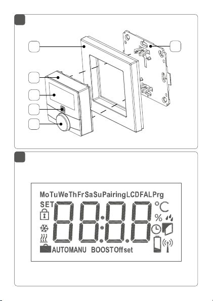
Geräteübersicht (s. Abbildung 1):
(A) Wechselrahmen
(B) Elektronikeinheit (Thermostat)
(C) Display
(D) Systemtaste (Anlerntaste und LED)
(E) Stellrad
(F) Montageplatte
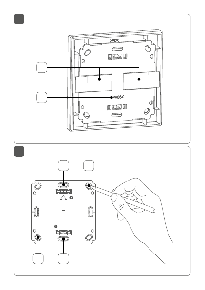
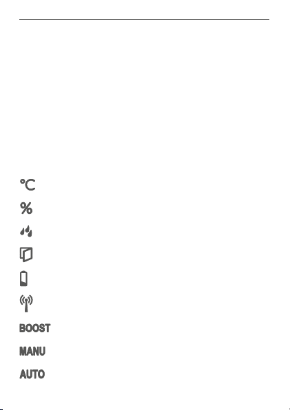
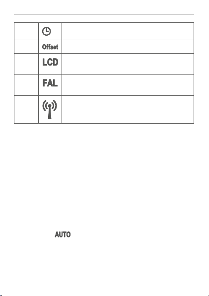
Displayübersicht (s. Abbildung 2):
Soll-/Ist-Temperatur
Luftfeuchtigkeit
Warnung für Betauung
Fenster-auf-Symbol
Batteriesymbol
Funkübertragung
Boost-Funktion
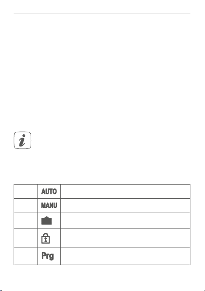
Manueller Betrieb
Automatikbetrieb
12
Page 13
Allgemeine Systeminformationen
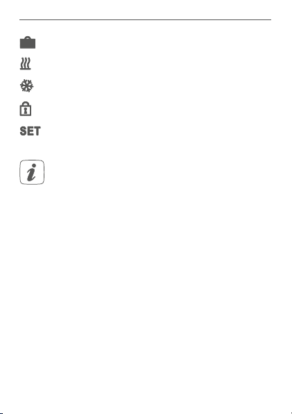
Urlaubsmodus
Heizen
Kühlen
Bediensperre
Soll-Temperatur
Alle weiteren Symbole finden Sie im Kapitel „6
Betriebsmodi und Konfiguration“ auf Seite 23.
4 Allgemeine Systeminformationen
Dieses Gerät ist Teil der Raumklimalösung von HomematicIP und kommuniziert über das Homematic IP Funkprotokoll. Alle Geräte der Raumklimalösung können komfortabel und individuell per Smartphone über die Homematic
onfiguriert werden. Welcher Funktionsumfang sich
IP App k
innerhalb des Homematic IP Systems im Zusammenspiel
mit weiteren Komponenten ergibt, entnehmen Sie bitte
dem HomematicIP Anwenderhandbuch. Alle technischen
Dokumente und Updates finden Sie stets aktuell unter
www.eQ-3.de.
13
Page 14

Inbetriebnahme
5 Inbetriebnahme
5.1 Anlernen
Bitte lesen Sie diesen Abschnitt erst vollständig,
bevor Sie mit dem Anlernen beginnen.
Damit der Wandthermostat in Ihr System integriert werden und mit anderen Geräten kommunizieren kann, muss
er zunächst angelernt werden.
Sie können den Wandthermostaten zur Steuerung Ihrer
Fußbodenheizung entweder direkt an den Homematic IP
Fußbodenheizungsaktor oder an den Homematic IP Access Point anlernen. Beim direkten Anlernen erfolgt die
Konfiguration am Gerät und beim Anlernen an den Access Point über die Homematic IP App.
5.1.1 Anlernen an den Homematic IP Fußbodenheizungsaktor
Halten Sie beim Anlernen einen Mindestabstand
von 50cm zwischen den Geräten ein.
Sie können den Anlernvorgang durch erneute
kurze Betätigung der Systemtaste (D) abbrechen.
Dies wird durch rotes Aufleuchten der GeräteLED bestätigt.
Wenn kein Anlernen erfolgt, wird der Anlernmodus automatisch nach 30 Sekunden beendet.
14
Page 15

Inbetriebnahme
Wenn Sie den Wandthermostaten an einen Homematic IP Fußbodenheizungsaktor anlernen möchten, müssen die beiden zu verknüpfenden Geräte in den Anlernmodus gebracht werden. Dafür gehen Sie wie folgt vor:
• Wählen Sie am Fußbodenheizungsaktor den gewünschten Kanal aus und aktivieren Sie den Anlernmodus über einen langen Tastendruck. Die
Geräte-LED beginnt orange zu blinken. Weitere
Informationen dazu entnehmen Sie bitte der Bedienungsanleitung des Fußbodenheizungsaktors.
• Fassen Sie die Elektronikeinheit (B) des Wandthermostaten seitlich an und ziehen Sie sie aus
dem Rahmen heraus (s. Abbildung 6).
• Drehen Sie die Elektronikeinheit (B) auf die Rückseite.
• Ziehen Sie den Isolierstreifen aus dem Batteriefach
des Wandthermostaten heraus.
• Drücken Sie die Systemtaste (D) des Wandthermostaten für mind. 4 s, um den Anlernmodus zu
aktivieren. Die Geräte-LED blinkt orange.
Erfolgreiches Anlernen wird durch grünes Blinken der
Geräte-LED (D) signalisiert.
War der Anlernvorgang nicht erfolgreich, leuchtet die
Geräte-LED (D) rot auf. Versuchen Sie es erneut.
15
Page 16

Inbetriebnahme
5.1.2 Anlernen an den Homematic IP Access Point
Richten Sie zunächst Ihren Homematic IP Access
Point über die Homematic IP App ein, um weitere
Homematic IP Geräte im System nutzen zu können. Ausführliche Informationen dazu finden Sie
in der Bedienungsanleitung des Access Points.
Zum Anlernen des Wandthermostats an den Access Point
gehen Sie wie folgt vor:
• Önen Sie die Homematic IP App auf Ihrem
Smartphone.
• Wählen Sie den Menüpunkt „Gerät anlernen“ aus.
• Fassen Sie die Elektronikeinheit (B) seitlich an und
ziehen Sie sie aus dem Rahmen heraus (s. Abbil-
dung 6).
• Drehen Sie die Elektronikeinheit (B) auf die Rückseite.
• Ziehen Sie den Isolierstreifen aus dem Batteriefach
des Wandthermostaten heraus.
• Der Anlernmodus ist für 3 Minuten aktiv.
Sie können den Anlernmodus manuell für weitere
3 Minuten starten, indem Sie die Systemtaste (D)
kurz drücken (s. Abbildung 8).
• Das Gerät erscheint automatisch in der Homematic IP App.
• Zur Bestätigung geben Sie in der App die letzten
16
Page 17

Inbetriebnahme
vier Ziern der Gerätenummer (SGTIN) ein oder
scannen Sie den QR-Code. Die Gerätenummer
finden Sie auf dem Aufkleber im Lieferumfang
oder direkt am Gerät.
• Warten Sie, bis der Anlernvorgang abgeschlossen
ist.
• Zur Bestätigung eines erfolgreichen Anlernvorgangs leuchtet die LED grün. Das Gerät ist nun
einsatzbereit.
• Leuchtet die LED rot, versuchen Sie es erneut.
• Wählen Sie die gewünschte Lösung für Ihr Gerät
aus.
• Ordnen Sie das Gerät in der App einem Raum zu
und vergeben Sie einen Namen für das Gerät.
5.2 Montage
Bitte lesen Sie diesen Abschnitt erst vollständig,
bevor Sie mit der Montage beginnen.
Sie können den Wandthermostat entweder im mitgelieferten Wechselrahmen (A) montieren oder ihn bequem in
eine bestehende Schalterserie integrieren (s. „5.2.4 Montage in Mehrfachkombinationen“ auf Seite 21).
Bei der Montage im Wechselrahmen können Sie den
Wandthermostat
• mit den mitgelieferten doppelseitigen Klebestreifen oder
17
Page 18

Inbetriebnahme
• mit den mitgelieferten Schrauben
an der Wand befestigen.
Alternativ können Sie den Wandthermostaten auf einer
Unterputzdose montieren.
5.2.1 Klebestreifenmontage
Um den zusammengesetzten Wandthermostat mit den
Klebestreifen zu montieren, gehen Sie wie folgt vor:
• Wählen Sie einen beliebigen Montageort aus.
Achten Sie darauf, dass der Montageuntergrund
glatt, eben, unbeschädigt, sauber, fett- sowie lösungsmittelfrei und nicht zu kühl ist, damit der
Klebestreifen langfristig haften kann.
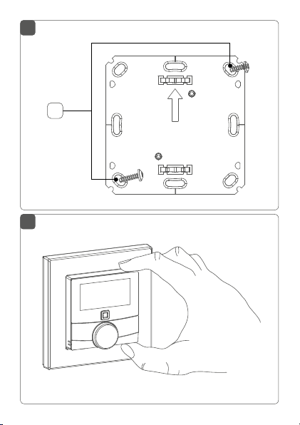
• Befestigen Sie die Klebestreifen (G) auf der Rückseite der Montageplatte (F) in den dafür vorgesehenen Markierungen. Achten Sie darauf, dass die
Schrift auf der Rück
seite für Sie lesbar ist (H) (s.
Abbildung 3) und die Klammern der Montageplat
te in die Önungen des Wandthermostats rasten.
•
Entfernen Sie die Folie von den Klebestreifen.
• Drücken Sie jetzt den zusammengebauten Wand
thermostat mit der Rückseite an die gewünschte
Position an die W
18
and.
-
-
Page 19
Inbetriebnahme
5.2.2 Schraubmontage
Um den Wandthermostat mithilfe der Schrauben zu
montieren, gehen Sie wie folgt vor:
• Wählen Sie einen geeigneten Montageort aus.
Stellen Sie sicher, dass an der ausgewählten Position in der Wand keine Leitungen verlaufen!
• Halten Sie die Montageplatte (F) an die gewünschte Montageposition. Achten Sie darauf,
dass der Pfeil auf der Vorderseite der Montageplatte nach oben zeigt.
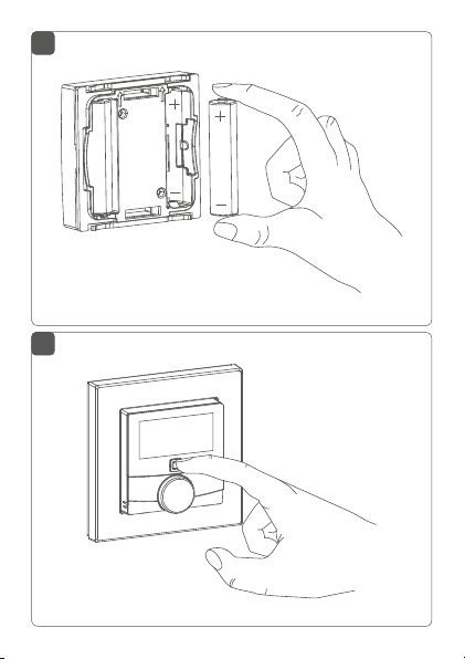
• Zeichnen Sie zwei der Bohrlöcher(J) anhand der
Montageplatte (diagonal gegenüberliegend) mit
einem Stift an der Wand an (s. Abbildung 4).
• Bohren Sie die vorgezeichneten Löcher.
Bei Steinwänden verwenden Sie einen 5 mm
Bohrer für die Dübel. Bei Holzwänden können Sie
einen 1,5mm Bohrer verwenden, um das Eindrehen der Schrauben zu erleichtern.
• Montieren Sie die Montageplatte durch Eindrehen der mitgelieferten Dübel und Schrauben (K)
(s. Abbilung 5).
• Setzen Sie den Wechselrahmen (A) auf die Montageplatte.
19
Page 20
Inbetriebnahme
• Setzen Sie die Elektronikeinheit (B) ein (s. Abbil-
dung 1). Achten Sie darauf, dass der Schriftzug
„TOP“ und die Pfeile auf der Rückseite nach oben
zeigen und die Klammern der Montageplatte in
die Önungen der Elektronikeinheit rasten.
5.2.3 Montage auf einer Unterputzdose
Sie können den Wandthermostaten mithilfe der Löcher(I)
auf einer Unterputz-/Installationsdose montieren (s. Ab-
bildung 4).
In der Unterputzdose dürfen sich keine oenen
Leiterenden befinden.
Sollten für die Montage bzw. Installation des Gerätes Änderungen oder Arbeiten an der Hausinstallation (z.B. Ausbau, Überbrücken von Schalter- oder
teckdoseneinsätzen) oder an der Niederspan-
S
nungsverteilung erforderlich sein, ist unbedingt
olgender Sicherheitshinweis zu beachten:
f
Hinweis! Installation nur durch Personen mit
einschlägigen elektrotechnischen Kenntnissen
und Erfahrungen!*
Durch eine unsachgemäße Installation gefährden Sie
• Ihr eigenes Leben;
• das Leben der Nutzer der elektrischen Anlage.
20
Page 21

Inbetriebnahme
Mit einer unsachgemäßen Installation riskieren Sie
schwere Sachschäden, z. B. durch Brand. Es droht für Sie
die persönliche Haftung bei Personen- und Sachschäden.
Wenden Sie sich an einen Elektroinstallateur!
Erforderliche Fachkenntnisse für die Installation:
*
Für die Installation sind insbesondere folgende Fachkenntnisse erforderlich:
• Die anzuwendenden „5 Sicherheitsregeln“:
Freischalten; gegen Wiedereinschalten sichern;
Spannungsfreiheit feststellen; Erden und Kurzschließen;
benachbarte, unter Spannung stehende Teile abdecken oder
abschranken;
• Auswahl des geeigneten Werkzeuges, der Messgeräte und ggf.
der persönlichen Schutzausrüstung;
• Auswertung der Messergebnisse;
• Auswahl des Elektro-Installationsmaterials zur Sicherstellung
der Abschaltbedingungen;
• IP-Schutzarten;
• Einbau des Elektroinstallationsmaterials;
• Art des Versorgungsnetzes (TN-System, IT-System, TT-System)
und die daraus folgenden Anschlussbedingungen (klassische
Nullung, Schutzerdung, erforderliche Zusatzmaßnahmen etc.).
5.2.4 Montage in Mehrfachkombinationen
Sie können den Wandthermostat sowohl mit dem mitgelieferten Rahmen (A), als auch mit Rahmen anderer
Hersteller verwenden oder die Elektronikeinheit (B) in einen Mehrfachrahmen integrieren. Sie können die Montageplatte (F) flexibel mit Klebestreifen oder Schrauben an
der Wand befestigen. Bei der Montage in Mehrfachkom-
21
Page 22

Inbetriebnahme
binationen ist darauf zu achten, dass die Montageplatte
des Wandthermostats bündig neben bereits befestigte
Montageplatten/Tragringen angebracht und daran ausgerichtet wird.
Der Wandthermostat passt in die Rahmen folgender Hersteller:
Hersteller Rahmen
Berker S.1, B.1, B.3, B.7 Glas
ELSO Joy
GIRA System 55, Standard 55, E2, E22, Event,
Esprit
merten 1-M, Atelier-M, M-Smart, M-Arc, M-Star,
M-Plan
JUNG A 500, AS 500, A plus, A creation
22
Page 23
Betriebsmodi und Konfiguration
6 Betriebsmodi und Konfiguration
Nach dem Anlernen und der Montage können Sie über
das Konfigurationsmenü Einstellungen vornehmen, um
das Gerät an Ihre persönlichen Bedürfnissen anzupassen.
Gehen Sie dafür wie folgt vor:
• Drücken Sie lange auf das Stellrad (E), um das
Konfigurationsmenü zu önen.
• Wählen Sie das gewünschte Symbol durch Drehen und kurzes Drücken des Stellrads aus, um
Einstellungen für die folgenden Menüpunkt vorzunehmen.
Durch langes Drücken des Stellrads gelangen Sie
zur vorheringen Ebene zurück.
Wenn für mehr als 1 Minute keine Betätigung am
Gerät erfolgt, schließt sich das Menü automatisch,
ohne eingestellte Änderungen zu übernehmen.
6.1 Automatikbetrieb
6.2
6.3 Urlaubsmodus
6.4
Manueller Betrieb
Bediensperre
6.5
Programmierung der Heizprofile
23
Page 24
Betriebsmodi und Konfiguration
6.6 Datum und Uhrzeit
6.7
6.8
Oset-Temperatur
Auswahl der gewünschten Temperaturanzeige
6.9
6.10
Konfiguration des Fußbodenheizungsaktors
Verbindungstest
6.1 Automatikbetrieb
Im Automatikbetrieb erfolgt die Temperaturregelung
gemäß dem eingestellten Wochenprofil (s. „6.5.3 Wochenprofil“ auf Seite 33). Manuelle Änderungen über
das Stellrad (E) bleiben bis zum nächsten Schaltzeitpunkt
aktiv. Danach wird das eingestellte Wochenprofil wieder
aktiviert. Um den Automatikbetrieb zu aktivieren, gehen
Sie wie folgt vor:
• Drücken Sie lange auf das Stellrad (E), um das
Konfigurationsmenü zu önen.
• Wählen Sie durch Drehen des Stellrads das Symbol „
durch kurzes Drücken des Stellrads.
24
“ aus und bestätigen Sie die Auswahl
Page 25
Betriebsmodi und Konfiguration
6.2 Manueller Betrieb
Im manuellen Betrieb erfolgt die Temperaturregelung
gemäß der am Stellrad (E) eingestellten Temperatur. Die
Temperatur bleibt bis zur nächsten manuellen Änderung
erhalten. Um den manuellen Betrieb zu aktivieren, gehen
Sie wie folgt vor:
• Drücken Sie lange auf das Stellrad (E), um das
Konfigurationsmenü zu önen.
• Wählen Sie durch Drehen des Stellrads das Symbol „
durch kurzes Drücken des Stellrads.
• Drehen Sie das Stellrad, um die gewünschte Temperatur einzustellen.
Sie können das Ventil komplett schließen bzw.
önen, indem Sie das Stellrad (E) bis zum Anschlag gegen den Uhrzeigersinn bzw. mit dem
Uhrzeigersinn drehen. Im Display wird entsprechend „OFF“ bzw. „On“ angezeigt.
“ aus und bestätigen Sie die Auswahl
6.3 Urlaubsmodus
Der Urlaubsmodus kann genutzt werden, wenn für einen
bestimmten Zeitraum (z. B. während eines Urlaubs oder einer Party) eine feste Temperatur gehalten werden soll. Um
den Urlaubsmodus einzustellen, gehen Sie wie folgt vor:
• Drücken Sie lange auf das Stellrad (E), um das
Konfigurationsmenü zu önen.
• Wählen Sie durch Drehen des Stellrads das Sym-
25
Page 26

Betriebsmodi und Konfiguration
bol „ “ aus und bestätigen Sie die Auswahl
durch kurzes Drücken des Stellrads.
• Stellen Sie durch Drehen des Stellrads StartUhrzeit und -Datum ein und bestätigen Sie die
Auswahl durch kurzes Drücken des Stellrads. Das
„S“ zeigt an, dass es sich um die Startzeit handelt.
• Stellen Sie durch Drehen des Stellrads End-Uhrzeit und -Datum ein und bestätigen Sie die Auswahl durch kurzes Drücken des Stellrads. Das „E“
zeigt an, dass es sich um die Endzeit handelt.
• Stellen Sie durch Drehen des Stellrads die Temperatur ein, die während der definierten Zeit gehalten werden soll und bestätigen Sie die Auswahl
durch kurzes Drücken des Stellrads.
• Wählen Sie durch Drehen des Stellrads aus, für
welche Räume der Urlaubsmodus aktiviert werden soll:
Auswahl „OnE“:
Urlaubsmodus wird für den aktuellen Wandthermostaten aktiviert.
Auswahl „ALL“:
Urlaubsmodus wird für alle Wandthermostate, die
an den Fußbodenheizungsaktor angelernt sind,
aktiviert.
26
Page 27

Betriebsmodi und Konfiguration
6.4 Bediensperre
Die Bedienung am Gerät kann gesperrt werden, um das
ungewollte Verändern von Einstellungen, z. B. durch versehentliches Berühren, zu verhindern. Um die Bediensperre zu aktivieren bzw. deaktivieren, gehen Sie wie folgt vor:
• Drücken Sie lange auf das Stellrad (E), um das
Konfigurationsmenü zu önen.
• Wählen Sie durch Drehen des Stellrads das Sym-
• Wählen Sie durch Drehen des Stellrads „On“, um
“ aus und bestätigen Sie die Auswahl durch
bol „
kurzes Drücken des Stellrads.
die Bediensperre zu aktivieren oder „OFF“, um die
Bediensperre zu deaktivieren.
Ist die Bediensperre aktiviert, können Sie über das
Konfigurationsmenü nur den Menüpunkt für die
Bediensperre (
die Bediensperre wieder deaktivieren.
) aufrufen. Hierüber können Sie
6.5 Programmierung der Heizprofile
Unter diesem Menüpunkt können Sie Einstellungen für
Ihre Heiz- bzw. Kühlprofile vornehmen und Wochenprofile nach Ihren eigenen Bedürfnissen erstellen.
• Drücken Sie lange auf das Stellrad (E), um das
Konfigurationsmenü zu önen.
• Wählen Sie durch Drehen des Stellrads das Sym-
“ aus und bestätigen Sie die Auswahl
bol „
durch kurzes Drücken des Stellrads.
27
Page 28

Betriebsmodi und Konfiguration
• Wählen Sie durch Drehen des Stellrads
- „type“ für das Auswählen zwischen Heizen
(„HEAT“) oder Kühlen („COOL“),
- „Pr.nr“ für das Auswählen der Wochenprofilnummer („nr. 1, nr. 2 ... nr. 6“),
- „Pr.Ad“ für das individuelle Einstellen des Wochenprofils und
- „OSSF“ zum Aktivieren („On“) bzw. Deaktivieren („OFF“) der Optimum-Start-/Stop-Funktion aus.
6.5.1 Heizen oder Kühlen
Sie können Ihre Fußbodenheizung im Winter zum Heizen
und im Sommer zum Kühlen verwenden.
• Wählen Sie im Menüpunkt „type“ durch Drehen
des Stellrads (E) „HEAT“ für Heizen oder „COOL“
für Kühlen aus und bestätigen Sie die Auswahl
durch kurzes Drücken des Stellrads.
6.5.2 Heizprofilnummer
Sie können zwischen den 6 folgenden, bereits vorkonfigurierten Profilen wählen.
• Wählen Sie im Menüpunkt „Pr.nr.“ durch Drehen
des Stellrads (E) die Nummer des gewünschten
Profils aus und bestätigen Sie die Auswahl durch
kurzes Drücken des Stellrads.
28
Page 29

Betriebsmodi und Konfiguration
Ist das gewählte Profil ein Heizprofil, wird geheizt,
sobald die Raumtemperatur unter den festgelegten Wert fällt. Ist das gewählte Profil ein Kühlprofil, wird gekühlt, sobald die Raumtemperatur über
den festgelegten Wert steigt.
Wird im Menü von „Heizen“ auf „Kühlen“ gewechselt, wird automatisch von Profil 1 auf 4, von Profil
2 auf 5 und von Profil 3 auf 6 gewechselt.
Profil 1
Vorkonfiguriert für Heizen per Heizkörperthermostat
Montag bis Freitag Temp.
00:00 bis 06:00 Uhr 17,0 °C
06:00 bis 09:00 Uhr 21,0 °C
09:00 bis 17:00 Uhr 17,0 °C
17:00 bis 22:00 Uhr 21,0 °C
22:00 to 23:59 Uhr 17,0 °C
Samstag bis Sonntag Temp.
00:00 bis 06:00 Uhr 17,0 °C
06:00 bis 22:00 Uhr 21,0 °C
22:00 to 23:59 Uhr 17,0 °C
29
Page 30

Betriebsmodi und Konfiguration
Profil 2
Vorkonfiguriert für Heizen per Fußbodenheizung
Montag bis Freitag Temp.
00:00 bis 05:00 Uhr 19,0 °C
05:00 bis 08:00 Uhr 21,0 °C
08:00 bis 15:00 Uhr 19,0 °C
15:00 bis 22:00 Uhr 21,0 °C
22:00 to 23:59 Uhr 19,0 °C
Samstag bis Sonntag Temp.
00:00 bis 06:00 Uhr 19,0 °C
06:00 bis 23:00 Uhr 21,0 °C
23:00 to 23:59 Uhr 19,0 °C
Profil 3
Alternatives Heizprofil
Montag bis Sonntag Temp.
00:00 bis 06:00 Uhr 17,0 °C
06:00 bis 22:00 Uhr 21,0 °C
22:00 to 23:59 Uhr 17,0 °C
30
Page 31

Betriebsmodi und Konfiguration
Profil 4
Alternatives Kühlprofil 1
Montag bis Freitag Temp.
00:00 bis 06:00 Uhr 17,0 °C
06:00 bis 09:00 Uhr 21,0 °C
09:00 bis 17:00 Uhr 17,0 °C
17:00 bis 22:00 Uhr 21,0 °C
22:00 to 23:59 Uhr 17,0 °C
Samstag bis Sonntag Temp.
00:00 bis 06:00 Uhr 17,0 °C
06:00 bis 22:00 Uhr 21,0 °C
22:00 to 23:59 Uhr 17,0 °C
31
Page 32

Betriebsmodi und Konfiguration
Profil 5
Vorkonfiguriert für Kühlen per Fußbodenheizung
Montag bis Freitag Temp.
00:00 bis 05:00 Uhr
23,0 °C
05:00 bis 08:00 Uhr 21,0 °C
08:00 bis 15:00 Uhr
23,0 °C
15:00 bis 22:00 Uhr 21,0 °C
22:00 to 23:59 Uhr
23,0 °C
Samstag bis Sonntag Temp.
00:00 bis 06:00 Uhr
23,0 °C
06:00 bis 23:00 Uhr 21,0 °C
23:00 to 23:59 Uhr
23,0 °C
Profil 6
Alternatives Kühlprofil 1
Montag bis Sonntag Temp.
00:00 bis 06:00 Uhr 17,0 °C
06:00 bis 22:00 Uhr 21,0 °C
22:00 to 23:59 Uhr 17,0 °C
32
Page 33

Betriebsmodi und Konfiguration
6.5.3 Wochenprofil
Im Wochenprofil lassen sich für jeden Wochentag des
gewählten Heizprofils separat bis zu 6 Heizphasen (13
Schaltzeitpunkte) individuell einstellen. Die Programmierung erfolgt für die ausgewählten Tage, wobei für einen
Zeitraum von 00:00 bis 23:59 Uhr Temperaturen hinterlegt werden können.
• Wählen Sie im Menüpunkt „Pr.Ad “ durch Drehen
des Stellrads (E) die Nummer des gewünschten
Profils aus und bestätigen Sie die Auswahl durch
kurzes Drücken des Stellrads.
• Wählen Sie unter „dAY“ durch Drehen des Stellrads bestimmte Wochentage, alle Werktage, das
Wochenende oder die gesamte Woche für Ihr
Heizprofil aus und bestätigen Sie die Auswahl
durch kurzes Drücken des Stellrads.
• Bestätigen Sie die Startzeit 00:00 Uhr durch kurzes Drücken des Stellrads.
• Wählen Sie durch Drehen des Stellrads die gewünschte Temperatur für die Startzeit aus und
bestätigen Sie die Auswahl durch kurzes Drücken
des Stellrads.
• Im Display wird die nächste Uhrzeit angezeigt. Sie
können diese Zeit mit dem Stellrad verändern.
• Wählen Sie durch Drehen des Stellrads die gewünschte Temperatur für den nächsten Zeitabschnitt aus und bestätigen Sie die Auswahl durch
kurzes Drücken des Stellrads.
33
Page 34

Betriebsmodi und Konfiguration
• Wiederholen Sie diesen Vorgang, bis für den gesamten Zeitraum von 0:00 bis 23:59 Uhr Temperaturen hinterlegt sind.
6.5.4 Optimum-Start-/Stop-Funktion
Damit zur festgelegten Zeit die gewünschte Temperatur
im Raum bereits erreicht wurde, können Sie die Optimum-Start-/Stop-Funktion aktivieren.
• Wählen Sie im Menüpunkt „OSSF“ durch Drehen
des Stellrads (E) „On“ für das Aktivieren oder „OFF“
für das Deaktivieren der Funktion aus und bestätigen Sie die Auswahl durch kurzes Drücken des
Stellrads.
6.6 Datum und Uhrzeit
Um Datum und Uhrzeit einzustellen, gehen Sie wie folgt
vor:
• Drücken Sie lange auf das Stellrad (E), um das
Konfigurationsmenü zu önen.
• Wählen Sie durch Drehen des Stellrads das Sym-
• Stellen Sie durch Drehen des Stellrads Jahr, Mo-
34
“ aus und bestätigen Sie die Auswahl durch
bol „
kurzes Drücken des Stellrads.
nat, Tag und Uhrzeit ein und bestätigen Sie durch
kurzes Drücken des Stellrads.
Page 35

Betriebsmodi und Konfiguration
6.7 Oset-Temperatur
Da die Temperatur am Wandthermostaten gemessen
wird, kann es an einer anderen Stelle im Raum kälter oder
wärmer sein. Um dies anzugleichen, kann eine OsetTemperatur von ±3.5 °C eingestellt werden. Werden z. B.
18 °C anstatt eingestellter 20 °C gemessen, ist ein Oset
von -2.0 °C einzustellen. Werksseitig ist eine Oset-Temperatur von 0.0 °C eingestellt. Um die Oset-Temperatur
individuell anzupassen, gehen Sie wie folgt vor:
• Drücken Sie lange auf das Stellrad (E), um das
Konfigurationsmenü zu önen.
• Wählen Sie durch Drehen des Stellrads das Symbol „
durch kurzes Drücken des Stellrads.
• Drehen Sie das Stellrad, bis die gewünschte Temperatur erscheint (max. ±3.5 °C).
• Bestätigen Sie durch kurzes Drücken des Stellrads.
“ aus und bestätigen Sie die Auswahl
6.8 Auswahl der gewünschten Temperaturanzeige
Sie können festlegen, welche Temperatur und ob die
Luftfeuchtigkeit im Display angezeigt werden soll.
• Drücken Sie lange auf das Stellrad (E), um das
Konfigurationsmenü zu önen.
• Wählen Sie durch Drehen des Stellrads das Symbol „
durch kurzes Drücken des Stellrads.
“ aus und bestätigen Sie die Auswahl
35
Page 36

Betriebsmodi und Konfiguration
• Wählen Sie durch Drehen des Stellrads
- „ACT“ für das Anzeigen der Ist-Temperatur,
- „SEt“ für das Anzeigen der Soll-Temperatur
oder
- „ACtH“ für das Anzeigen der Ist-Temperatur
und der aktuellen Luftfeuchtigkeit im Wechsel aus und bestätigen Sie Ihre Auswahl durch
kurzes Drücken des Stellrads.
6.9 Konfiguration des Fußbodenheizungsaktors
Unter diesem Menüpunkt können Sie Einstellungen für
Ihren Homematic IP Fußbodenheizungsaktor vornehmen.
• Drücken Sie lange auf das Stellrad (E), um das
Konfigurationsmenü zu önen.
• Wählen Sie durch Drehen des Stellrads das Sym-
• Ist der Wandthermostat an mehr als einen Fußbo-
• Wählen Sie aus, ob Sie Geräteparameter („UnP1/
• Stellen Sie Vor- sowie Nachlaufzeiten der Pumpe,
36
“ aus und bestätigen Sie die Auswahl
bol „
durch kurzes Drücken des Stellrads.
denheizungsaktor angelernt, wählen Sie mit dem
Stellrad die gewünschte Fußbodenheizung aus.
UnP2“) oder Kanalparameter („ChAn“) konfigurieren wollen.
Eco-Temperaturen, Zeitintervalle etc. ganz individuell ein.
Page 37

Bedienung
Weitere Informationen zu den Konfigurationsmöglichkeiten entnehmen Sie bitte der Bedienungsanleitung des
Homematic IP Fußbodenheizungsaktors.
6.10 Verbindungstest
Sie können die Verbindung zwischen Ihrem Homematic IP Wandthermostaten und dem Homematic IP Fußbodenheizungsaktor überprüfen. Bei dieser Überprüfung
sendet der Wandthermostat einen Schaltbefehl an den
Fußbodenheizungsaktor und je nachdem in welchem
Schaltzustand sich der Aktor befindet, schaltet er sich
nach Erhalt des Befehls zur Bestätigung ein bzw. aus.
• Drücken Sie lange auf das Stellrad (E), um das
Konfigurationsmenü zu önen.
• Wählen Sie durch Drehen des Stellrads das Sym“ aus und bestätigen Sie die Auswahl durch
bol „
kurzes Drücken des Stellrads.
7 Bedienung
Nach der Konfiguration stehen Ihnen einfache Bedienfunktionen direkt am Gerät zur Verfügung.
Befindet sich der Wandthermostat im Stand-byModus, müssen Sie vor der Bedienung einmal das
Stellrad (E) drücken, um ihn zu aktivieren.
37
Page 38

Batterien wechseln
• Temperatur: Drehen Sie das Stellrad (E) nach
rechts oder links, um die Temperatur manuell zu
verändern. Im Automatikbetrieb bleibt die manuell eingestellte Temperatur bis zum nächsten
Schaltzeitpunkt bestehen. Danach wird das eingestellte Wochenprofil wieder aktiviert. Im manuellen Betrieb bleibt die Temperatur bis zur nächsten manuellen Änderung erhalten.
• Boost-Funktion für Homematic IP Heizkörper-
thermostate: Drücken Sie das Stellrad (E) des
Wandthermostats kurz, um die Boost-Funktion
für schnelles, kurzzeitiges Aufheizen des Heizkörpers durch Önung des Ventils zu aktivieren.
Dadurch wird sofort ein angenehmes Wärmegefühl im Raum erreicht.
8 Batterien wechseln
Erscheint das Symbol für leere Batterien ( ) im Display
bzw. in der App, tauschen Sie die verbrauchten Batterien
gegen zwei neue Batterien des Typs LR03/Micro/AAA aus.
Beachten Sie dabei die richtige Polung der Batterien.
Um die Batterien des Wandthermostats zu wechseln, gehen Sie wie folgt vor:
• In montiertem Zustand lässt sich die Elektro-
nikeinheit (B) einfach aus dem Rahmen (A) und
von der Montageplatte (F) ziehen. Fassen Sie die
38
Page 39

Batterien wechseln
Elektronikeinheit seitlich an und ziehen Sie sie aus
dem Rahmen heraus (s. Abbildung 6). Das Önen
des Gerätes ist nicht erforderlich.
• Drehen Sie die Elektronikeinheit auf die Rücksei-
te, um die Batterien zu entnehmen bzw. sie einzulegen.
• Legen Sie zwei neue 1,5 V LR03/Micro/AAA Bat-
terien polungsrichtig gemäß Markierung in die
Batteriefächer ein (s. Abbildung 7).
• Setzen Sie die Elektronikeinheit wieder in den
Rahmen. Achten Sie darauf, dass der Schriftzug
„TOP“ und die Pfeile auf der Rückseite der Elektronikeinheit nach oben zeigen und die Klammern der Montageplatte in die Önungen der
Elektronikeinheit rasten.
• Achten Sie nach dem Einlegen der Batterien auf
die Blinkfolgen der LED (s. „9.4 Fehlercodes und
Blinkfolgen“ auf Seite 42).
Nach dem Einlegen der Batterien führt der Wandthermostat zunächst einen Selbsttest für ca. 2 Sekunden durch.
Danach erfolgt die Initialisierung. Den Abschluss bildet
die Test-Anzeige: Oranges und grünes Leuchten.
Batterien dürfen niemals aufgeladen werden.
Batterien nicht ins Feuer werfen! Batterien nicht
übermäßiger Wärme aussetzen. Batterien nicht
kurzschließen. Es besteht Explosionsgefahr!
39
Page 40

Fehlerbehebung
Verbrauchte Batterien gehören nicht in den
Hausmüll! Entsorgen Sie diese in Ihrer örtlichen
Batteriesammelstelle!
9 Fehlerbehebung
9.1 Schwache Batterie
Wenn es der Spannungswert zulässt, ist der Wandthermostat auch bei niedriger Batteriespannung betriebsbereit. Je nach Beanspruchung kann evtl. nach kurzer
Erholungszeit der Batterien wieder mehrfach gesendet
werden.
Bricht beim Senden die Spannung wieder zusammen,
wird das Symbol für leere Batterien (
code am Gerät angezeigt (s. „9.4 Fehlercodes und Blinkfolgen“ auf Seite 42). Tauschen Sie in diesem Fall die
leeren Batterien gegen zwei neue aus (s. „8 Batterien
wechseln“ auf Seite 38).
9.2 Befehl nicht bestätigt
Bestätigt mindestens ein Empfänger einen Befehl nicht,
leuchtet zum Abschluss der fehlerhaften Übertragung die
LED rot auf. Grund für die fehlerhafte Übertragung kann
eine Funkstörung sein (s. „12 Allgemeine Hinweise zum
Funkbetrieb“ auf Seite 46). Die fehlerhafte Übertragung
kann folgende Ursachen haben:
• Empfänger nicht erreichbar,
• Empfänger kann Befehl nicht ausführen (Lastaus-
40
) und der Fehler-
Page 41

Fehlerbehebung
fall, mechanische Blockade etc.) oder
• Empfänger defekt.
9.3 Duty Cycle
Der Duty Cycle beschreibt eine gesetzlich geregelte Begrenzung der Sendezeit von Geräten im 868-MHz-Bereich. Das Ziel dieser Regelung ist es, die Funktion aller im
868-MHz-Bereich arbeitenden Geräte zu gewährleisten.
In dem von uns genutzten Frequenzbereich 868 MHz beträgt die maximale Sendezeit eines jeden Gerätes 1 % einer Stunde (also 36 Sekunden in einer Stunde). Die Geräte
dürfen bei Erreichen des 1-%-Limits nicht mehr senden,
bis diese zeitliche Begrenzung vorüber ist. Gemäß dieser
Richtlinie, werden Homematic IP Geräte zu 100 % normenkonform entwickelt und produziert.
Im normalen Betrieb wird der Duty Cycle in der Regel
nicht erreicht. Dies kann jedoch in Einzelfällen bei der Inbetriebnahme oder Erstinstallation eines Systems durch
vermehrte und funkintensive Anlernprozesse der Fall sein.
Eine Überschreitung des Duty-Cycle-Limits wird durch
dreimal langsames rotes Blinken der LED angezeigt und
kann sich durch temporär fehlende Funktion des Gerätes
äußern. Nach kurzer Zeit (max. 1 Stunde) ist die Funktion
des Gerätes wiederhergestellt.
41
Page 42

Fehlerbehebung
9.4 Fehlercodes und Blinkfolgen
Fehler- und
Blinkcode
Batteriesymbol (
Antennensymbol blinkt
)
(
Luftfeuchtesysmbol
blinkt (
Betauungsund Kühlsymbol blinken
)
(
Schlosssymbol
)
(
42
Bedeutung Lösung
Batterie-
)
spannung
gering
Kommunikationsstörung
zum Homematic IP Access
Point/Fußbodenheizungsaktor
Feuchtegrenze
(60 %) im Raum
)
überschritten
Feuchteeingang bei Multi
IO Box wurde
aktiviert
Bediensperre
aktiv
Tauschen Sie die
Batterien des
Gerätes aus (s. „8
Batterien wechseln“ auf Seite
38).
Prüfen Sie die
Verbindung zum
Homematic IP
Access Point/Fußbodenheizungsaktor.
Lüften Sie und
stellen Sie ggf.
vom Kühl- auf
Heizbetrieb um
Lüften Sie und
stellen Sie ggf. von
Kühl- auf Heizbetrieb um
Deaktivieren Sie
die Bediensperre
in der App/im
Menü.
Page 43

Fehlerbehebung
Kurzes oranges Blinken
1x langes
grünes
Leuchten
1x langes rotes
Leuchten
Kurzes oranges Blinken
(alle 10 s)
Kurzes oranges Leuchten
(nach grüner
oder roter
Empfangsmeldung)
1x langes rotes
Leuchten
Funkübertragung/Sendeversuch/Da-
Warten Sie, bis
die Übertragung
beendet ist.
tenübertragung
Vorgang
bestätigt
Sie können mit
der Bedienung
fortfahren.
Vorgang
fehlgeschlagen
Versuchen Sie es
erneut (s. „9.2 Befehl nicht bestätigt“
auf Seite 40).
Anlernmodus
aktiv
Geben Sie die
letzten vier Ziern
der GeräteSeriennummer zur
Bestätigung ein (s.
„5.1 Anlernen“ auf
Seite 14).
Batterien leer Tauschen Sie die
Batterien aus (s. „8
Batterien wechseln“ auf Seite
38).
Vorgang
fehlgeschlagen
oder DutyCycle-Limit
erreicht
Versuchen Sie es
erneut („9.2 Befehl
nicht bestätigt“ auf
Seite 40 oder
„9.3 Duty Cycle“
auf Seite 41).
43
Page 44

Wiederherstellung der Werkseinstellungen
6x langes
rotes Blinken
1x oranges
und 1x grünes
Leuchten
(nach dem
Einlegen der
Batterien)
Gerät defekt Achten Sie auf die
Anzeige in Ihrer
App oder wenden
Sie sich an Ihren
Fachhändler.
Testanzeige Nachdem die
Testanzeige
erloschen ist,
können Sie fortfahren.
10 Wiederherstellung der Werksein-
stellungen
Die Werksteinstellungen des Gerätes können
wiederhergestellt werden. Dabei gehen alle Einstellungen verloren.
Um die Werkseinstellungen des Wandthermostats wiederherzustellen, gehen Sie wie folgt vor:
• Fassen Sie die Elektronikeinheit (B) seitlich an und
ziehen Sie sie aus dem Rahmen heraus (s. Abbil-
dung 6).
• Entnehmen Sie eine Batterie.
• Legen Sie die Batterie entsprechend der Polari-
tätsmarkierungen wieder ein (s. Abbildung 7) und
halten Sie gleichzeitg die Systemtaste (D) für 4 s
gedrückt, bis die LED schnell orange zu blinken
44
Page 45

Wartung und Reinigung
beginnt (s. Abbildung 8).
• Lassen Sie die Systemtaste wieder los.
• Drücken Sie die Systemtaste erneut für 4 s, bis die
LED grün aufleuchtet.
• Lassen Sie die Systemtaste wieder los, um das
Wiederherstellen der Werkseinstellungen abzuschließen.
Das Gerät führt einen Neustart durch.
11 Wartung und Reinigung
Das Gerät ist für Sie bis auf einen eventuell erforderlichen Batteriewechsel wartungsfrei. Überlassen
Sie eine W
Reinigen Sie das Gerät mit einem weichen, sauberen, trockenen und fusselfreien Tuch. Für die Entfernung von stärkeren Verschmutzungen kann das Tuch leicht mit lauwarmem Wasser angefeuchtet werden. Verwenden Sie keine
lösemittelhaltigen Reinigungsmittel, das K
und die Beschriftung können dadurch angegrien werden.
artung oder Reparatur einer Fachkraft.
unststogehäuse
45
Page 46

Allgemeine Hinweise zum Funkbetrieb
12 Allgemeine Hinweise zum Funk-
betrieb
Die Funk-Übertragung wird auf einem nicht exklusiven
Übertragungsweg realisiert, weshalb Störungen nicht
ausgeschlossen werden können. Weitere Störeinflüsse
können hervorgerufen werden durch Schaltvorgänge,
Elektromotoren oder defekte Elektrogeräte.
Die Reichweite in Gebäuden kann stark von der im
Freifeld abweichen. Außer der Sendeleistung und
den Empfangseigenschaften der Empfänger spielen
Umwelteinflüsse wie Luftfeuchtigkeit neben bauli
chen Gegebenheiten vor Ort eine wichtige Rolle.
Hiermit erklärt die eQ-3 AG, dass sich dieses Gerät in
Übereinstimmung mit den grundlegenden Anforderungen und den anderen relevanten Vorschriften der Richtlinie 1999/5/EG befindet. Die vollständige Konformitätserklärung finden Sie unter www.eQ-3.de.
46
-
Page 47

Technische Daten
13 Technische Daten
Geräte-Kurzbezeichnung:
Versorgungsspannung: 2x 1,5 V LR03/Micro/AAA
Stromaufnahme: 50 mA max.
Batterielebensdauer: 2 Jahre (typ.)
Schutzart: IP20
Umgebungstemperatur: 0 bis 35 °C
Abmessungen (B x H x T):
Ohne Rahmen: 55 x 55 x 23,5 mm
Mit Rahmen: 86 x 86 x 25 mm
Gewicht: 100 g (inkl. Batterien)
Funkfrequenz: 868,3 MHz/869,525 MHz
Empfängerkategorie: SRD category 2
Typ. Funk-Freifeldreichweite: 250 m
Duty Cycle: < 1 % pro h/< 10 % pro h
Wirkungsweise: Typ 1
Verschmutzungsgrad: 2
Technische Änderungen vorbehalten.
HmIP-WTH-2
47
Page 48

Technische Daten
Entsorgungshinweis
Gerät nicht im Hausmüll entsorgen! Elektronische Geräte sind entsprechend der Richtlinie
über Elektro- und Elektronik-Altgeräte über die
örtlichen Sammelstellen für Elektronik-Altgeräte
zu entsorgen.
Konformitätshinweis
Das CE-Zeichen ist ein Freiverkehrszeichen, das
sich ausschließlich an die Behörden wendet und
keine Zusicherung von Eigenschaften beinhaltet.
Bei technischen Fragen zum Gerät wenden Sie
sich bitte an Ihren Fachhändler.
48
Page 49

Package contents
Quantity Description
1
1 Clip-on frame
1 Mounting plate
2 Double-sided adhesive strips
2 Screws 3.0 x 30 mm
2 Plugs 5 mm
2 1.5 V LR03/micro/AAA batteries
1 Operating manual
Documentation © 2016 eQ-3 AG, Germany
All rights reserved. Translation from the original version in German. This manual may not be reproduced in any format, either in
whole or in part, nor may it be duplicated or edited by electronic,
mechanical or chemical means, without the written consent of
the publisher.
Typographical and printing errors cannot be excluded. However,
the information contained in this manual is reviewed on a regular
basis and any necessary corrections will be implemented in the
next edition. We accept no liability for technical or typographical
errors or the consequences thereof.
All trademarks and industrial property rights are acknowledged.
Printed in Hong Kong
Changes may be made without prior notice as a result of technical advances.
143304 (web)
Version 1.2 (11/2016)
Homematic IP Wall Thermostat with
Humidity Sensor
49
Page 50

Table of contents
1 Information about this manual....................................52
2 Hazard information ........................................................52
3 Function and device overview ....................................54
4 General system information ........................................56
5 Start-up ............................................................................56
5.1 Teaching-in ..........................................................................56
5.1.1 Pairing with the Homematic IP Floor Heating
Actuator ....................................................................57
5.1.2 Teaching-in to the Homematic IP Access Point ..
5.2 Mounting .............................................................................. 60
6 Operating modes and configuration ........................ 64
6.1 Automatic mode ................................................................. 66
6.2 Manual operation ................................................................ 66
6.3 Holiday mode .......................................................................67
6.4 Operating lock ..................................................................... 68
6.5 Programming of heating profiles ....................................68
6.6 Date and time .......................................................................75
50
58
5.2.1 Adhesive strip mounting ....................................... 60
5.2.2 Screw mounting ......................................................61
5.2.3 Mounting on flush-mounted boxes .................. 62
5.2.4 Installation in multiple combinations ................ 64
6.5.1 Heating or cooling ................................................. 69
6.5.2 Heating profile numbers ...................................... 69
6.5.3 Week profile .............................................................73
6.5.4 Optimum start/stop function ...............................74
Page 51

6.7 Oset temperature ..............................................................75
6.8 Selecting the desired temperature display .....................76
6.9 Configuring the floor heating actuator ...........................76
6.10 Communication test ...........................................................77
7 Operation .........................................................................78
8 Replacing batteries ........................................................79
9 Troubleshooting ............................................................ 80
9.1 Weak battery ........................................................................80
9.2 Command not confirmed .................................................. 81
9.3 Duty cycle ............................................................................ 81
9.4 Error codes and flashing sequences .............................. 82
10 Restore factory settings ............................................... 84
11 Maintenance and cleaning ...........................................85
12 General information about radio operation ............ 86
13 Technical specifications ................................................87
51
Page 52

Information about this manual
1 Information about this manual
Please read this manual carefully before beginning
operation with your Homematic IP components. Keep
the manual so you can refer to it at a later date if you
need to.
If you hand over the device to other persons for use,
please hand over this manual as well.
Symbols used:
Attention!
This indicates a hazard.
Please note:
This section contains important additional
information.
2 Hazard information
Do not open the device. It does not contain any
parts that can be maintained by the user. In the
event of an error, please have the device checked
by an expert.
For safety and licensing reasons (CE),
unauthorized change and/or modification of the
device is not permitted.
52
Page 53

Hazard information
The device may only be operated in dry and dustfree environment and must be protected from
the eects of moisture, vibrations, solar or other
methods of heat radiation, cold and mechanical
loads.
The device is not a toy; do not allow children to
play with it. Do not leave packaging material lying
around. Plastic films/bags, pieces of polystyrene,
etc. can be dangerous in the hands of a child.
We do not assume any liability for damage to
property or personal injury caused by improper
use or the failure to observe the hazard
information. In such cases, any claim under
warranty is extinguished! For consequential
damages, we assume no liability!
The device may only be operated within
residential buildings.
Using the device for any purpose other than that
described in this operating manual does not fall
within the scope of intended use and shall
invalidate any warranty or liability.
53
Page 54

Function and device overview
3 Function and device overview
The Homematic IP Wall Thermostat oers timecontrolled regulation of floor heating systems in
connection with Homematic IP Floor Heating Actuators
or conventional radiators using Homematic IP Radiator
Thermostats according to individually tailored heating
phases.
The wall thermostat serves to measure the temperature
and humidity in a room. The data is cyclically transmitted
to a floor heating actuator or radiator thermostats in
order to regulate the room temperature precisely.
You can pair the wall thermostat directly with a
Homematic IP Floor Heating Actuator or teach it in to the
Homematic IP Access Point in order to control the device
comfortably via Homematic IP app.
Thanks to battery operation, the device is highly flexible
where mounting and selecting a mounting location are
concerned. The device is mounted and removed very
easily with the supplied clip-on frame using screws or
adhesive strips. It is compatible with a number of dierent
surfaces including furniture, brick walls, tiles or glass. It is
also possible to integrate the wall thermostat into existing
switches.
54
Page 55

Function and device overview
Device overview (see figure 1):
(A) Clip-on frame
(B) Electronic unit (thermostat)
(C) Display
(D) System button (teach-in button and LED)
(E) Control wheel
(F) Mounting plate
Display overview (see figure 2):
Set/actual temperature
Humidity
Warning about condensation
Open window symbol
Battery symbol
Radio transmission
Boost function
Manual operation
Automatic mode
Holiday mode
Heating
55
Page 56

General system information
Cooling
Operating lock
Setpoint temperature
You will find a description of all symbols in section „6
Operating modes and configuration“ on page 64.
4 General system information
This device is part of the climate control solution of
Homematic IP and works with the Homematic IP radio
protocol. All devices of the climate control solution can be
configured comfortably and individually with a smartphone
via the Homematic IP app. The available functions provided
by the Homematic IP system in combination with other
components are described in the Homematic IP User
Guide. All current technical documents and updates are
provided at www.eQ-3.de.
5 Start-up
5.1 Teaching-in
Please read this entire section before starting
the teach-in procedure.
To integrate the wall thermostat into your system and
56
Page 57

Start-up
enable it to communicate with other devices, you must
teach it in first.
You can either pair the wall thermostat directly with the
Homematic IP Floor Heating Actuator or teach it in to the
Homematic IP Access Point. After pairing, configuration
has to be done directly on the device. After teachingin to the Access Point, configuration is done via the
Homematic IP app.
5.1.1 Pairing with the Homematic IP Floor Heating Actuator
Please make sure you maintain a distance of at
least 50cm between the devices.
You can cancel the pairing procedure by briefly
pressing the system button (D) again. This will be
indicated by the device LED lighting up red.
If no teach-in operations are carried out, teach-in
mode is exited automatically after 30 seconds.
If you want to pair the wall thermostat with a HomematicIP
Floor Heating Actuator, the pairing mode of both devices
has to be activated first. To do this, proceed as follows:
• Select the required channel of the floor heating
actuator and activate the pairing mode using a
long button press. The device LED starts to flash
57
Page 58

Start-up
orange. For further information, please refer to
the user manual of the floor heating actuator.
• To remove the electronic unit (B) of the wall
thermostat from the frame, take hold of the sides
of the electronic unit and pull it out (see figure 6).
• Turn over the electronic unit (B).
• Remove the insulation strip from the battery
compartment of the wall thermostat.
• Press and hold down the system button (D) of the
wall thermostat for at least 4 seconds to activate
the pairing mode. The device LED flashes orange.
The device LED (D) lights up green to indicate that
teaching-in has been successful.
If pairing failed, the device LED (D) lights up red. Please
try again.
5.1.2 Teaching-in to the Homematic IP Access Point
First set up your Homematic IP Access Point via
the Homematic IP app to enable operation of
other Homematic IP devices within your system.
For further information, please refer to the
operating manual of the Access Point.
To teach-in your wall thermostat to the Access Point,
please proceed as follows:
• Open the Homematic IP app on your smartphone.
• Select the menu item “Teach-in device”.
58
Page 59

Start-up
• To remove the electronic unit (B) from the frame,
take hold of the sides of the electronic unit and
pull it out (see figure 6).
• Turn over the electronic unit (B).
• Remove the insulation strip from the battery
compartment of the wall thermostat.
• Teach-in mode remains activated for 3 minutes.
You can manually start the teach-in mode for
another 3 minutes by pressing the system button
(D) briefly (see figure 8).
• Your device will automatically appear in the
Homematic IP app.
• To confirm, please enter the last four digits of
the device number (SGTIN) in your app or scan
the QR code. Therefore, please see the sticker
supplied or attached to the device.
• Please wait until teach-in is completed.
• If teaching-in was successful, the LED lights up
green. The device is now ready for use.
• If the LED lights up red, please try again.
• Select the desired solution for your device.
• Allocate the device to a room and give the device
a name.
59
Page 60

Start-up
5.2 Mounting
Please read this entire section before starting to
mount the device.
You can use the supplied clip-on frame (A) to mount
the wall thermostat or easily integrate it into an existing
switch (see „5.2.4 Installation in multiple combinations“
on page 64).
If you want to mount the wall thermostat with the
supplied clip-on frame, you can use
• the supplied double-sided adhesive strips or
• the supplied screws
to fix it to a wall.
You can also mount the wall thermostat on a flushmounting box.
5.2.1 Adhesive strip mounting
For mounting the assembled wall thermostat with the
adhesive strips, please proceed as follows:
• Choose a site for installation.
Make sure that the mounting surface is smooth,
solid, non-disturbed, free of dust, grease and
solvents and not too cold to ensure long-time
adherence.
60
Page 61

Start-up
• Fix the adhesive strips (G) on the back side of the
mounting plate (F) in the provided area. Make
sure that you can read the letters on the back
(see figure 3)
side (H)
mounting plate latch into the
and that the clips on the
openings on the
wall thermostat.
• Remove the protective film from the adhesive
strips.
• Press the assembled wall thermostat with the
back side to the wall in the position where it
should subsequently be attached.
5.2.2 Screw mounting
For mounting the wall thermostat by screws, please
proceed as follows:
• Choose a site for installation.
Make sure that no electricity or similar lines run in
the wall at this location!
• Position the mounting plate (F) on the desired
site on the wall. Make sure that the arrow on the
mounting plate is pointing upwards.
• Use a pen to mark the positions of bore holes (J)
(diagonally opposite) in the mounting plate on
the wall (see figure 4).
• Now drill the bore holes.
61
Page 62

Start-up
If you are working with a stone wall, drill the
marked two 5 mm holes and insert the plugs
supplied. If you are working with a wooden wall,
you can pre-drill 1.5mm holes to make screws
easier to insert.
• Use the supplied screws and plugs (K) to fasten
the mounting plate to the wall (see figure 5).
• Attach the clip-on frame (A) to the mounting
plate.
• Place the electronic unit (B) back into the frame
(see figure 1). Make sure that “TOP” and the
arrows on the back side point upwards and that
the clips on the mounting plate latch into the
openings on the electronic unit.
5.2.3 Mounting on flush-mounted boxes
You can mount the wall thermostat on flush-mounting/
installation boxes using the holes (I) (see figure 4).
If the device is mounted to a flush-mounting box,
there may be no open conductor ends.
If changes or works have to be made on the house
installation (e.g. extension, bypass of switch- or
socket inserts) or the low-voltage distribution for
mounting or installing the device, the following
safety instruction must be considered:
62
Page 63

Start-up
Please note! Only to be installed by persons with
the relevant electro-technical knowledge and
experience!*
Incorrect installation can put
• your own life at risk;
• and the lives of other users of the electrical
system.
Incorrect installation also means that you are running the
risk of serious damage to property, e.g. because of a fire.
You may be personally liable in the event of injuries or
damage to property.
Contact an electrical installer!
*Specialist knowledge required for installation:
The following specialist knowledge is particularly important during
installation:
• The “5 safety rules” to be used:
Disconnect from mains; Safeguard from switching on again;
Check that system is deenergised; Earth and short circuit;
Cover or cordon o neighbouring live parts;
• Select suitable tool, measuring equipment and, if necessary,
personal safety equipment;
• Evaluation of measuring results;
• Selection of electrical installation material for safeguarding
shut-o conditions;
• IP protection types;
• Installation of electrical installation material;
• Type of supply network (TN system, IT system, TT system) and
the resulting connecting conditions (classical zero balancing,
protective earthing, required additional measures etc.).
63
Page 64

Operating modes and configuration
5.2.4 Installation in multiple combinations
You can mount the wall thermostat with the attachment
frame (A) provided or use it with frames of other
manufacturers as well as integrate the electronic unit (B)
into a multi-gang frame. You can flexibly fix the mounting
plate (F) to the wall using adhesive strips or screws. For
mounting with multiple combinations, make sure that
the mounting plate of the wall thermostat is seamlessly
aligned to the already fixed mounting plate/retaining ring.
The wall thermostat is designed to fit into frames supplied
by the following manufacturers:
Manufacturer Frame
Berker S.1, B.1, B.3, B.7 glass
ELSO Joy
GIRA System 55, Standard 55, E2, E22,
merten 1-M, Atelier-M, M-Smart, M-Arc, M-
JUNG A 500, AS 500, A plus, A creation
Event, Esprit
Star, M-Plan
6 Operating modes and
configuration
After teaching-in and mounting the device, you can
individually adjust the settings to your personal needs via
64
Page 65

Operating modes and configuration
the configuration menu. To do this, proceed as follows:
• Press and hold down the control wheel (E) to
open the configuration menu.
• Select the desired symbol by turning the control
wheel and pressing it briefly if you want to adjust
the settings of the following menu items.
Press and hold down the control wheel to get
back to the previous level. The menu
automatically closes without applying changes if
there is no operation for more than 1 minute.
6.1 Automatic mode
6.2
6.3
6.4
Manual operation
Holiday mode
Operating lock
6.5
6.6
6.7
6.8
Programming of heating profiles
Date and time
Oset temperature
Selecting the desired temperature display
6.9 Configuring the floor heating actuator
6.10
Communication test
65
Page 66

Operating modes and configuration
6.1 Automatic mode
In automatic mode, the temperature is controlled in
accordance with the set week profile (see „6.5.3 Week
profile“ on page 73). Manual changes that are set via
the control wheel (E) are activated until the next point
at which the profile changes. Afterwards, the defined
heating profile will be activated again. To activate the
automatic mode, please proceed as follows:
• Press and hold down the control wheel (E) to
open the configuration menu.
• Select the
wheel and confirm by pressing the control wheel
briefly.
symbol by turning the control
6.2 Manual operation
In manual mode, the temperature is controlled in
accordance with the current temperature set via the
control wheel (E). The temperature remains activated
until the next manual change. To activate the manual
mode, please proceed as follows:
• Press and hold down the control wheel (E) to
open the configuration menu.
• Select the
wheel and confirm by pressing the control wheel
briefly.
• Turn the control wheel to set the desired
temperature.
66
symbol by turning the control
Page 67

Operating modes and configuration
You can fully close or open the vale by turning the
control wheel (E) as far as it will go in an anticlockwise or clockwise direction. “OFF” or “On” is
displayed.
6.3 Holiday mode
The holiday mode can be used if you want to maintain a
fixed temperature for a certain period (e.g. during your
holidays or a party). To activate the holiday mode, please
proceed as follows:
• Press and hold down the control wheel (E) to
open the configuration menu.
• Select the
wheel and confirm by pressing the control wheel
briefly.
• Select the start time and date by turning the
control wheel and confirm by pressing the
control wheel briefly. “S” indicates a start time.
• Select the end time and date by turning the
control wheel and confirm by pressing the
control wheel briefly. “E” indicates an end time.
• Set the temperature that you want to maintain
during the defined time using the control wheel
and confirm by pressing the control wheel briefly.
• Select by turning the control wheel in which
rooms you want to activate the holiday mode:
“OnE”: Holiday mode is activated for the current
wall thermostat.
symbol by turning the control
67
Page 68

Operating modes and configuration
“ALL”: Holiday mode is activated for all wall thermostats that are connected to the floor heating
actuator.
6.4 Operating lock
Operation of the device can be locked to avoid settings
being changed unintended (e.g. through involuntary
touch). To activate the operating lock, please proceed as
follows:
• Press and hold down the control wheel (E) to
open the configuration menu.
• Select the
and confirm by pressing the control wheel briefly.
• Turn the control wheel to select “On” in order to
activate the operating lock or “OFF” to deactivate
the operating lock.
symbol by turning the control wheel
If the operating lock is activated you can only
enter the menu item “Operating lock” (
configuration menu. You can deactivate the
operating lock here.
) via the
6.5 Programming of heating profiles
You can use this menu item for configuring heating and
cooling profiles and to adjust the week profiles according
to your personal needs.
• Press and hold down the control wheel (E) to
open the configuration menu.
68
Page 69

Operating modes and configuration
• Select the symbol by turning the control wheel
and confirm by pressing the control wheel briefly.
• Turn the control wheel and select
- “type” for switching between heating (”HEAT”)
or cooling (”COOL”),
- “Pr.nr” to set the week profile number (”no. 1,
no. 2 ... no. 6”),
- “Pr.Ad” for individual settings of the week
profile and
- “OSSF” for activating (”On”) or deactivating
(”OFF”) the optimum start/stop function.
6.5.1 Heating or cooling
You can use your floor heating system to heat rooms
during winter or to cool rooms during summer.
• Select “HEAT” for heating and “COOL” for cooling
in the menu item “type” by turning the control
wheel (E) and confirm by pressing the control
wheel briefly.
6.5.2 Heating profile numbers
You can select between the following 6 pre-configured
profiles.
• Select the number of the required profile in the
menu item “Pr.nr.” by turning the control wheel (E)
and confirm by pressing the control wheel briefly.
69
Page 70

Operating modes and configuration
If the selected profile is a heating profile, the room
is heated as soon as the temperature falls below
the defined value. If the selected profile is a
cooling profile, the room is cooled as soon as the
temperature increases the defined value. After
switching from “heating” to “cooling” in the menu,
the profiles are changed from profile 1 to 4, profile
2 to 5 and from profile 3 to 6 automatically.
Profile 1: Pre-configured heating via radiator thermostat
Monday to Friday Temp.
00:00 - 06:00 17.0 °C
06:00 - 09:00 21.0 °C
09:00 - 17:00 17.0 °C
17:00 - 22:00 21.0 °C
22:00 - 23:59 17.0 °C
Saturday to Sunday Temp.
00:00 - 06:00 17.0 °C
06:00 - 22:00 21.0 °C
22:00 - 23:59 17.0 °C
70
Page 71

Operating modes and configuration
Profile 2: Pre-configured heating via floor heating
Monday to Friday Temp.
00:00 - 05:00 19.0 °C
05:00 - 08:00 21.0 °C
08:00 - 15:00 19.0 °C
15:00 - 22:00 21.0 °C
22:00 - 23:59 19.0 °C
Saturday to Sunday Temp.
00:00 - 06:00 19.0 °C
06:00 - 23:00 21.0 °C
23:00 - 23:59 19.0 °C
Profile 3: Alternative profile
Monday to Sunday Temp.
00:00 - 06:00 17.0 °C
06:00 - 22:00 21.0 °C
22:00 - 23:59 17.0 °C
71
Page 72

Operating modes and configuration
Profile 4: Alternative cooling profile 1
Monday to Friday Temp.
00:00 - 06:00 17.0 °C
06:00 - 09:00 21.0 °C
09:00 - 17:00 17.0 °C
17:00 - 22:00 21.0 °C
22:00 - 23:59 17.0 °C
Saturday to Sunday Temp.
00:00 - 06:00 17.0 °C
06:00 - 22:00 21.0 °C
22:00 - 23:59 17.0 °C
Profile 5: Pre-configured cooling via floor heating
Monday to Friday Temp.
00:00 - 05:00
23.0 °C
05:00 - 08:00 21.0 °C
08:00 - 15:00
23.0 °C
15:00 - 22:00 21.0 °C
22:00 - 23:59
23.0 °C
72
Page 73

Operating modes and configuration
Saturday to Sunday Temp.
00:00 - 06:00
23.0 °C
06:00 - 23:00 21.0 °C
23:00 - 23:59
23.0 °C
Profile 6: Alternative cooling profile 1
Monday to Sunday Temp.
00:00 - 06:00 17.0 °C
06:00 - 22:00 21.0 °C
22:00 - 23:59 17.0 °C
6.5.3 Week profile
In the week profile, for each weekday up to 6 heating
phases (13 change settings) can be set separately.
The programming is carried out for the selected days,
whereby temperature settings have to be set for the
entire period between 00:00 and 23:59h.
• Select the number of the required profile in the
menu item “Pr.Ad” by turning the control wheel
(E) and confirm by pressing the control wheel
briefly.
• In the menu item “dAy” you can select single days
of the week, all weekdays, the weekend or the
73
Page 74

Operating modes and configuration
entire week for your heating profile and confirm
by pressing the control wheel briefly.
• Confirm the start time 00:00 by pressing the
control wheel briefly.
• Select the desired temperature for the start time
by turning the control wheel and confirm by
pressing the control wheel briefly.
• The next time is shown in the display. You can
change this time using the control wheel.
• Select the desired temperature for the next
period by turning the control wheel and confirm
by pressing the control wheel briefly.
• Repeat this procedure until temperatures are
stored for the entire period between 0:00 and
23:59h.
6.5.4 Optimum start/stop function
To reach the desired temperature in the room at the
defined time you can activate the optimum start/stop
function.
• Select “On” for activating or “OFF” for deactivating
the function in the menu item “OSSF” by turning
the control wheel (E) and confirm by pressing the
control wheel briefly.
74
Page 75

Operating modes and configuration
6.6 Date and time
To set the date and time, please proceed as follows:
• Press and hold down the control wheel (E) to
open the configuration menu.
• Select the
and confirm by pressing the control wheel briefly.
• Set the year, month, day and hour by turning
the control wheel and confirm by pressing the
control wheel briefly.
symbol by turning the control wheel
6.7 Oset temperature
As the temperature is measured on the wall thermostat,
the temperature distribution can vary throughout a room.
To adjust this, a temperature oset of ±3.5 °C can be set.
If a nominal temperature of e.g. 20 °C is set but the room
presents with only 18 °C, an oset of -2.0 °C needs to
be set. An oset temperature of 0.0° is set in the factory
settings. To adjust the oset temperature, please proceed
as follows:
• Press and hold down the control wheel (E) to
open the configuration menu.
• Select the
wheel and confirm by pressing the control wheel
briefly.
• Turn the control wheel until the desired
temperature appears (±3.5 °C maximum).
• Confirm by pressing the control wheel briefly.
symbol by turning the control
75
Page 76

Operating modes and configuration
6.8 Selecting the desired temperature display
You can adjust the temperature to be displayed. You can
also define whether the humidity value shall be displayed
or not.
• Press and hold down the control wheel (E) to
open the configuration menu.
• Select the
wheel and confirm by pressing the control wheel
briefly.
• Turn the control wheel and select
- “ACT” to display the actual temperature,
- “SEt” to display the setpoint temperature,
- “ACtH” for alternating between the actual
temperature and humidity display and
confirm by pressing the control wheel briefly.
symbol by turning the control
6.9 Configuring the floor heating actuator
You can use this menu item for configuring your
Homematic IP Floor Heating Actuator.
• Press and hold down the control wheel (E) to
open the configuration menu.
• Select the
wheel and confirm by pressing the control wheel
briefly.
• If the wall thermostat is connected to more than
one floor heating actuator, please select the
required floor heating using the control wheel.
• Please define if you want to configure the
76
symbol by turning the control
Page 77

Operating modes and configuration
device parameters (”UnP1/UnP2”) or the channel
parameters (”ChAn”).
• You can individually adjust the line-up time/
follow-up time, eco temperatures, intervals etc.
For further information regarding the configuration
options, please refer to the user manual of the floor
heating actuator.
6.10 Communication test
You can check the connection between your
Homematic IP Wall Thermostat and the Homematic
IP Floor Heating Actuator. During this test, the wall
thermostat transmits a switching command to the floor
heating actuator. Depending on the current status of the
actuator, the device is switched on or o for confirmation
after receiving the command.
• Press and hold down the control wheel (E) to
open the configuration menu.
• Select the
and confirm by pressing the control wheel briefly.
symbol by turning the control wheel
77
Page 78

Operation
7 Operation
After configuration, simple operations are available
directly on the device.
If the wall thermostat is in standby mode, please
press the control wheel (E) once before operation
to activate the device.
• Temperature: Turn the control wheel (E) to
the right or to the left to manually change the
temperature. In automatic mode, the manually
set temperature will remain the same until
the next point at which the profile changes.
Afterwards, the defined heating profile will be
activated again. During manual operation, the
temperature remains activated until the next
manual change.
• Boost function for Homematic IP Radiator
Thermostats: Press the control wheel (E) of
the wall thermostat briefly to activate the boost
function for heating up the radiator quickly and
briefly by opening the valve. There will be a
pleasant room temperature right away because
of the radiated heat.
78
Page 79

Replacing batteries
8 Replacing batteries
If the symbol for empty batteries ( ) appears in the display
or in the app, please replace the used batteries by two
new LR03/micro/AAA batteries. You must observe the
correct battery polarity.
To replace the batteries of the wall thermostat, please
proceed as follows:
• Once mounted, the electronic unit (B) can easily
be pulled out of the frame (A) and removed from
the mounting plate (F). To remove the electronic
unit from the frame, take hold of the sides of the
electronic unit and pull it out (see figure 6). You
do not need to open the device.
• Turn the electronic unit over to remove or insert
the batteries.
• Insert two new 1.5 V LR03/micro/batteries into
the battery compartment, making sure that you
insert them the right way round (see figure 7).
• Put the electronic unit back into the frame. Make
sure that “TOP” and the arrows on the back side
of the electronic unit point upwards and that
the clips on the mounting plate latch into the
openings on the electronic unit.
• Please pay attention to the flashing signals of the
device LED while inserting the batteries (see „9.4
Error codes and flashing sequences“ on page 82).
79
Page 80

Troubleshooting
Once the batteries have been inserted, the wall
thermostat will perform a self-test/restart (approx. 2
seconds). Afterwards, initialisation is carried out. The test
display will indicate that initialisation is complete: orange
and green lighting.
Never recharge standard batteries. Do not throw
the batteries into a fire. Do not expose batteries
to excessive heat. Do not short-circuit batteries.
Doing so will present a risk of explosion.
Used batteries should not be disposed of with
regular domestic waste! Instead, take them to
your local battery disposal point.
9 Troubleshooting
9.1 Weak battery
Provided that the voltage value permits it, the wall
thermostat will remain ready for operation also if the
battery voltage is low. Depending on the particular load,
it may be possible to send transmissions again repeatedly,
once the batteries have been allowed a brief recovery
period. If the voltage drops too far during transmission,
the empty battery symbol (
code will be displayed on the device (see „9.4 Error codes
and flashing sequences“ on page 82). In this case,
replace the empty batteries by two new batteries (see „8
Replacing batteries“ on page 79).
80
) and the corresponding error
Page 81

Troubleshooting
9.2 Command not confirmed
If at least one receiver does not confirm a command,
the device LED lights up red at the end of the failed
transmission process. The failed transmission may be
caused by radio interference (see „6.5 Programming of
heating profiles“ on page 68). This may be caused be
the following:
• Receiver cannot be reached.
• Receiver is unable to execute the command (load
failure, mechanical blockade, etc.).
• Receiver is defective.
9.3 Duty cycle
The duty cycle is a legally regulated limit of the
transmission time of devices in the 868 MHz range. The
aim of this regulation is to safeguard the operation of all
devices working in the 868 MHz range.
In the 868 MHz frequency range we use, the maximum
transmission time of any device is 1% of an hour (i.e. 36
seconds in an hour). Devices must cease transmission
when they reach the 1% limit until this time restriction
comes to an end. Homematic IP devices are designed
and produced with 100% conformity to this regulation.
During normal operation, the duty cycle is not usually
reached. However, repeated and radio-intensive teachin processes mean that it may be reached in isolated
instances during start-up or initial installation of a system.
If the duty cycle is exceeded, this is indicated by three
81
Page 82

Troubleshooting
slow flashes of the device LED, and may manifest itself
in the device temporarily working incorrectly. The device
starts working correctly again after a short period (max.
1 hour).
9.4 Error codes and flashing sequences
Error and
flashing codes
Battery
symbol (
Antenna
symbol flashing
)
(
Flashing
humidity
symbol (
Flashing
condensation
and cooling
symbol (
82
Meaning Solution
Battery
)
voltage too low
Communication
error with
Homematic IP
Access Point/
floor heating
actuator
Humidity
limit (60 %) in
)
the room is
exceeded
Humidity input
of Multi IO
Box has been
)
activated
Replace the
batteries of the
device (see „8
Replacing batteries“
on page 79).
Please check the
connection to the
Homematic IP
Access Point/floor
heating actuator.
Ventilate the room
and switch from
cooling to heating
mode, if required.
Ventilate the room
and switch from
cooling to heating
mode, if required.
Page 83

Troubleshooting
Lock symbol
)
(
Short orange
flashing
1x long green
lighting
1x long red
lighting
Short orange
flashing
(every 10
seconds)
Short orange
lighting (after
green or red
confirmation)
Operating lock
activated
Radio
transmission/
attempting to
transmit/data
transmission
Operation
confirmed
Operation
failed
Teach-in mode
active
Batteries empty
Deactivate the
operating lock
via the app or the
menu.
Wait until the
transmission is
completed.
You can continue
operation.
Please try again
(s. „9.2 Command
not confirmed“ on
page 81).
Please enter the
last four numbers
of the device
serial number for
confirmation (see
„5.1 Teaching-in“
on page 56).
Replace the
batteries (see „8
Replacing batteries“
on page 79).
83
Page 84

Restore factory settings
1x long red
lighting
6x long red
flashing
1x orange
and 1 x green
lighting (after
inserting
batteries)
Transmission
failed or duty
cycle limit is
reached
Device
defective
Test display After the test
Please try again
(see sec. „9.2
Command not
confirmed“ on
page 81 or „9.3
Duty cycle“ on
page 81).
Please see your
app for error
message or
contact your
retailer.
display
has stopped,
you can continue.
10 Restore factory settings
The factory settings of the device can be restored.
If you do this, you will lose all your settings.
To restore the factory settings of the wall thermostat,
please proceed as follows:
• To remove the electronic unit (B) from the frame,
take hold of the sides of the electronic unit and
pull it out (see figure 6).
• Remove a battery.
84
Page 85

Maintenance and cleaning
• Insert the battery ensuring that the polarity is
correct (see figure 7) and press and hold down
the system button (D) for 4 seconds at the same
time, until the LED will quickly start flashing
orange (see figure 8).
• Release the system button again.
• Press and hold down the system button again for
4 seconds, until the status LED lights up green.
• Release the system button to finish the procedure.
The device will perform a restart.
11 Maintenance and cleaning
The device does not require you to carry out any
maintenance other than replacing the battery
when necessary. Enlist the help of an expert to
carry out any maintenance or repairs.
Clean the device using a soft, lint-free cloth that is clean
and dry. You may dampen the cloth a little with lukewarm
water in order to remove more stubborn marks. Do not use
any detergents containing solvents, as they could corrode
the plastic housing and label.
85
Page 86

General information about radio operation
12 General information about radio
operation
Radio transmission is performed on a non-exclusive
transmission path, which means that there is a possibility
of interference occurring. Interference can also be
caused by switching operations, electrical motors or
defective electrical devices.
The range of transmission within buildings can
dier greatly from that available in the open air.
Besides the transmitting power and the reception
characteristics of the receiver, environmental
factors such as humidity in the vicinity have an
important role to play, as do on-site structural/
screening conditions.
eQ-3 AG hereby declares that this device complies with
the essential requirements and other relevant regulations
of Directive 1999/5/EC.
You can find the full declaration of conformity at
www.eQ-3.de.
86
Page 87

Technical specifications
13 Technical specifications
Device short description:
Supply voltage: 2x 1.5 V LR03/micro/AAA
Current consumption: 50 mA max.
Battery life: 2 years (typ.)
Degree of protection: IP20
Ambient temperature: 0 to 35 °C
Dimensions (W x H x D):
Without frame: 55 x 55 x 23.5 mm
Including frame: 86 x 86 x 25 mm
Weight: 100 g (including batteries)
Radio frequency: 868.3 MHz/869.525 MHz
Receiver category: SRD category 2
Typ. open area RF range: 250 m
Duty cycle: < 1 % per h/< 10 % per h
Method of operation: Type 1
Degree of pollution: 2
Subject to technical changes.
HmIP-WTH-2
87
Page 88

Technical specifications
Instructions for disposal
Do not dispose of the device with regular
domestic waste! Electronic equipment must be
disposed of at local collection points for waste
electronic equipment in compliance with the
Waste Electrical and Electronic Equipment
Directive.
Information about conformity
The CE sign is a free trading sign addressed
exclusively to the authorities and does not
include any warranty of any properties.
For technical support, please contact your
retailer.
88
Page 89

Technical specifications
89
Page 90

Kostenloser Download der Homematic IP App!
Free download of the Homematic IP app!
Bevollmächtigter des Herstellers:
Manufacturer’s authorised representative:
eQ-3 AG
Maiburger Straße 29
26789 Leer / GERMANY
www.eQ-3.de
 Loading...