

Page 1
OPERATOR’S MANUAL
MANUEL D’UTILISATION
MANUAL DEL OPERADOR
ELECTRIC STRING
TRIMMER/EDGER
TAILLE-HAIES À LIGNE / TAILLE-BORDURES
ÉLECTRIQUE
RECORTADORA ELÉCTRICA DE HILO / PARA
RECORTAR BORDES
UT41112B
To register your Homelite
product, please visit:
http://register.homelite.com/
Pour enregistrer votre produit de
Homelite, s’il vous plaît la visite:
http://register.homelite.com/
Para registrar su producto de
Homelite, por favor visita:
http://register.homelite.com/
Your string trimmer has been engineered and manufactured to Homelite’s high standard for dependability, ease of operation,
and operator safety. When properly cared for, it will give you years of rugged, trouble-free performance.
WARNING: To reduce the risk of injury, the user must read and understand the operator’s manual before
using this product.
Thank you for buying a Homelite product.
SAVE THIS MANUAL FOR FUTURE REFERENCE
Cette taille-bordures à ligne a été conçue et fabriquée conformément
aux strictes normes de fiabilité, simplicité d’emploi et sécurité
d’utilisation de Homelite. Correctement entretenue, elle vous donnera
des années de fonctionnement robuste et sans problème.
AVERTISSEMENT : Pour réduire les risques de
blessures, l’utilisateur doit lire et veiller à bien comprendre le
manuel d’utilisation avant d’employer ce produit.
Merci d’avoir acheté un produit Homelite.
CONSERVER CE MANUEL POUR
FUTURE RÉFÉRENCE
Su recortadora de hilo ha sido diseñada y fabricada de
conformidad con las estrictas normas de Homelite para brindar
fiabilidad, facilidad de uso y seguridad para el operador. Con el
debido cuidado, le brindará muchos años de sólido y eficiente
funcionamiento.
ADVERTENCIA: Para reducir el riesgo de lesiones,
el usuario debe leer y comprender el manual del operador antes
de usar este producto.
Le agradecemos la compra de un producto Homelite.
GUARDE ESTE MANUAL PARA
FUTURAS CONSULTAS
Page 2
See this fold-out section for all the figures referenced in the operator’s manual.
Voir que cette section d’encart pour toutes les
figures a adressé dans le manuel d’utilisation.
Vea esta sección de la página desplegable para
todas las figuras mencionó en el manual del operador.
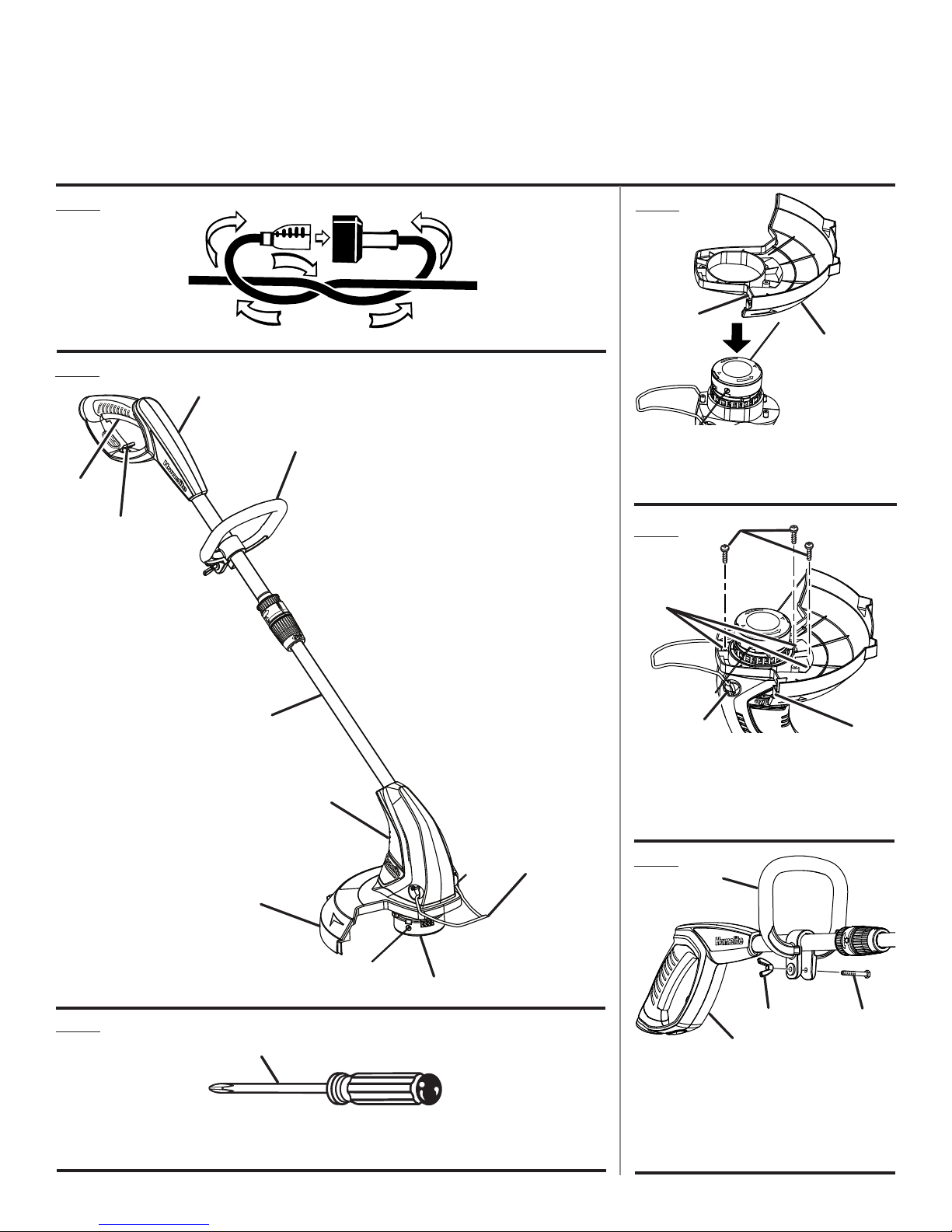
Fig. 1
Fig. 2
a
Fig. 4
B
a
C
d
B
A - Switch trigger (gâchette, gatillo del
interruptor)
B - Cord retainer (retenue de cordon, retén para
el cable)
C - Rotating rear handle (poignée arrière
rotative, cómo rotar el mango trasero)
D - Front handle (poignée avant, mango
delantero)
E - Telescoping shaft (flèche télescopique, brazo
telescópico)
F - Trimmer head (tête du taille-bordures,
cabezal de la recortadora)
G - Air vents (évents d’aération, rejillas de
ventilación)
H - Edger guide (guidage du taille-bordure, guía
para recortar bordes)
I - Grass deflector (déflecteur d’herbe, deflector
de hierba)
A - Grass deflector (déflecteur d’herbe, deflector
de hierba)
B - Line cut-off blade (lame couple ligne,
cuchilla de cortar el hilo)
Fig. 5
a
B
Fig. 3
E
G
I
a
A - Phillips screwdriver (tournevis phillips,
destornillador phillips)
C
A - Screws (vis, tornillos)
B - Screw holes (orifices de las vis, agujeros del
tornillo)
C - Button (bouton, botón)
D - Line cut-off blade (lame couple ligne,
cuchilla de cortar el hilo)
H
Fig. 6
a
d
F
d
C
B
A - Front handle (poignée avant, mango
delantero)
B - Rear handle shaft (arbre de la poignée
arrière, eje del mango trasero)
C - Bolt (boulon, perno)
D - Wing nut (écrou à oreilles, tuerca de
mariposa)
ii
Page 3
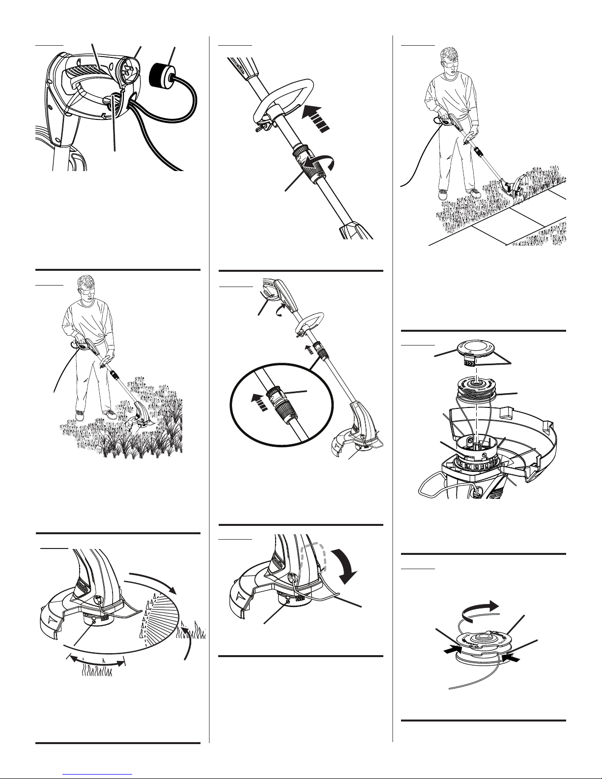
Fig. 7
a
d
C
B
A - Switch trigger (gâchette, gatillo del
interruptor)
B - Cord retainer (retenue de cordon, retén para
el cable)
C - Extension cord outlet end (cordon
prolongateurs extremité de la prise
d’alimentation, extremo del enchufe de
cordón de extensión)
D - Plug (bouchon, tapón)
Fig. 8
Fig. 10
a
A - Telescoping coupler (bouton de la flèche
télescopique, botón del drazo telescópico)
Fig. 11
a
Fig. 13
pROpER EdGING OpERaTING pOSITION
pOSITION COUpE-BORdURES
d’UTILISaTION CORRECTE
pOSICIóN RECORTadORa dE BORdES
CORRECTa paRa EL MaNEjO dE La
HERRaMIENTa
pROpER TRIMMER OpERaTING
pOSITION
pOSITION TaILLE-HaIES d’UTILISaTION
CORRECTE
pOSICIóN RECORTadORa CORRECTa
paRa EL MaNEjO dE La HERRaMIENTa
Fig. 9
a
C
B
A - Rear handle (poignée arrière, mango
trasero)
B - Pull up edging coupler to rotate (tirer en
haut le bouton du taille-bordure afin de
faire pivoter l’outil, arránquese el botón del
recorte de bordes para rotar)
Fig. 12
a
A - Edger guide (guidage de bordure, guía para
el recorte de bordes)
Fig. 14
a
d
A - Spool retainer (retenue de bobine, retén del
carrete)
B - Spool (bobine, carrete)
C - Tabs (languettes, pestañas)
D - Slots (fentes, ranuras)
Fig. 15
WINd CLOCKWISE
ENROULER daNS LE SENS HORaIRE
ENROLLE HaCIa La dERECHa
B
C
B
a
B
B
A - Direction of rotation (sens de rotation,
sentido de la rotación)
B - Best cutting area (d’efficacité, área de corte
óptima)
C - Dangerous cutting area (zone de coup
dangereuse, área de corte peligrosa)
A - Spool (bobine, carrete)
B - Hole (trou, agujero)
iii
Page 4

TABLE OF CONTENTS
TABLE DES MATIÈRES / ÍNDICE DE CONTENIDO
Introduction ......................................................................................................................................................................2
Introduction / Introducción
Important Safety Instructions ........................................................................................................................................ 3-4
Instructions importantes concernant la sécurité / Instrucciones de seguridad importantes
Symbols ............................................................................................................................................................................ 5
Symboles / Símbolos
Electrical ........................................................................................................................................................................... 6
Caractéristiques électriques / Aspectos eléctricos
Features ............................................................................................................................................................................7
Caractéristiques / Características
Assembly .......................................................................................................................................................................7-8
Assemblage / Armado
Operation .......................................................................................................................................................................8-9
Utilisation / Funcionamiento
Maintenance ................................................................................................................................................................... 10
Entretien/ Mantenimiento
Troubleshooting .............................................................................................................................................................. 11
Dépannage / Corrección de problema
Warranty .........................................................................................................................................................................12
Garantie/Garantía
Parts Ordering and Service ...............................................................................................................................Back Page
Commande de pièces et réparation / Pedidos de piezas y servicio ......................................................... Page arrière / Pág. posterior
INTRODUCTION
INTRODUCTION / INTRODUCCIÓN
This product has many features for making its use more pleasant and enjoyable. Safety, performance, and dependability
have been given top priority in the design of this product making it easy to maintain and operate.
* * *
Ce produit offre de nombreuses fonctions destinées à rendre son utilisation plus plaisante et satisfaisante. Lors de la
conception de ce produit, l’accent a été mis sur la sécurité, les performances et la fiabilité, afin d’en faire un outil facile à
utiliser et à entretenir.
* * *
Este producto ofrece numerosas características para hacer más agradable y placentero su uso. En el diseño de este producto
se ha conferido prioridad a la seguridad, el desempeño y la fiabilidad, por lo cual se facilita su manejo y mantenimiento.
Page 2
Page 5

IMPORTANT SAFETY INSTRUCTIONS
WARNING:
Read and understand all instructions before using this
product. Failure to follow all instructions listed below may
result in electric shock, fire and/or serious personal injury.
READ ALL INSTRUCTIONS
For safe operation, read and understand all instructions
before using this product. Follow all safety instructions.
Failure to follow all safety instructions listed below, can
result in serious personal injury.
Do not allow children or untrained individuals to use this
unit.
Check the work area before each use. Remove all objects
such as rocks, broken glass, nails, wire, or line which can
be thrown or become entangled in the machine.
Always wear eye protection with side shields marked to
comply with ANSI Z87.1.
Use Safety Glasses – Always use face or dust mask if
operation is dusty.
Dress Properly – Use rubber gloves and substantial
footwear is recommended when working outdoors. Wear
heavy, long pants, long sleeves, boots, and gloves. Do
not wear loose fitting clothing or jewelry or anything that
can be caught in moving parts. Secure long hair above
shoulder level to prevent entanglement in moving parts.
Do not wear loose fitting clothing, short pants, sandals,
or go barefoot.
Keep children away - Keep all bystanders, children, and
pets at least 50 ft. away.
Stay alert - Watch what you are doing. Use common
sense. Do not operate this unit when you are tired, ill, or
under the influence of alcohol, drugs, or medication.
Do not operate in poor lighting.
Keep all parts of your body away from any moving part.
Do not operate power tools in explosive atmospheres,
such as in the presence of flammable liquids, gases, or
dust. Power tools create sparks which may ignite the dust
or fumes.
To reduce the risk of electric shock, this tool has a po-
larized plug (one blade is wider than the other) and will
require the use of a polarized extension cord. The plug
will fit into a polarized extension cord only one way. If the
plug does not fit fully into the extension cord, reverse the
plug. If the plug still does not fit, obtain a correct polarized
extension cord. A polarized extension cord will require
the use of a polarized wall outlet. This plug will fit into the
polarized wall outlet only one way. If the plug does not fit
fully into the wall outlet, reverse the plug. If the plug still
does not fit, contact a qualified electrician to install the
proper wall outlet. Do not change the equipment plug,
extension cord receptacle, or extension cord plug in any
way.
Avoid body contact with grounded surfaces such as
radiators, ranges, and refrigerators. There is an increased
risk of electric shock if your body is grounded.
Avoid Dangerous Environments - Don’t expose trimmers
to rain or wet conditions. Water entering a power tool will
increase the risk of electric shock.
WARNING! – To reduce the risk of electric shock -
outdoor extension cordsmarked W-A, W,
STW-A, STOW-A, SJW-A, SJTW-A, or SJTOW-A.
cords are rated for outdoor use and reduce the risk of electric shock.
Ground Fault Circuit Interrupter (GFCI) protection should
be provided on the circuit(s) or outlet(s) to be used for the
gardening appliance. Receptacles are available having
built-in GFCI protection and may be used for this measure
of safety.
Use Right Appliance - Do not force trimmer. Use the cor-
rect tool for your application. The correct tool will do the
job better and safer at the rate for which it is designed.
Don’t Force Appliance – It will do the job better and with
less likelihood of a risk of injury at the rate for which it
was designed.
Do not operate the equipment while barefoot or when
wearing sandals or similar lightweight footwear. Wear
protective footwear that will protect your feet and improve
your footing on slippery surfaces.
Do not overreach – Keep firm footing and balance. Over-
reaching can result in loss of balance.
Avoid Accidental Start – Do not carry plugged in appliance
with finger on trigger. Be sure the switch trigger is not engaged before plugging in.
Do not use tool if switch trigger does not turn it on or off.
Any tool that cannot be controlled with the switch trigger
is dangerous and must be repaired.
Disconnect appliance – Remove trimmer from power
source before storing, servicing, changing accessories
such as cutting line and when not in use. Such preventive safety measures reduce the risk of starting the tool
accidentally.
Use only identical manufacturer’s replacement parts and
accessories. Use of any other parts may create a hazard
or cause product damage.
Maintain appliance with care - Replace string head if
cracked, chipped, or damaged in any way. Be sure the
string head is properly installed and securely fastened.
Failure to do so can cause serious injury.
Follow instructions for lubricating and changing
accessories. Inspect appliance cord periodically, and
if damaged, have it repaired by an authorized service
facility. Inspect extension cords periodically and replace
SW-A, SOW-A,
pipes,
Use
These
Page 3 — English
Page 6

IMPORTANT SAFETY INSTRUCTIONS
if damaged. Keep handles dry, clean, and free from oil
and grease.
Follow instructions for lubricating and changing
accessories. Inspect appliance cord periodically, and
if damaged, have it repaired by an authorized service
facility. Inspect extension cords periodically and replace
if damaged. Keep handles dry, clean, and free from oil
and grease.
Make sure all guards, straps, deflectors and handles are
properly and securely attached.
Use only the manufacturer’s 0.065 in. diameter replace-
ment line in the cutting head. Do not use any other cutting
attachment, for example, metal wire, rope, or the like. To
install any other brand of cutting head to this string trimmer can result in serious personal injury.
Never operate unit without the grass deflector in place
and in good condition.
Check damaged parts - Before further use of the tool, a
guard or other part that is damaged should be carefully
checked to determine that it will operate properly and
perform its intended function. Check for alignment of
moving parts, binding of moving parts, breakage of parts,
mounting and any other conditions that may affect its
operation. A guard or other part that is damaged must
be properly repaired or replaced by an authorized service
center to avoid risk of personal injury.
Maintain a firm grip on both handles while trimming. Keep
string head below waist level. Never cut with the string
head located over 30 in. or more above the ground.
Store idle appliances indoors- When not in use, string
trimmer should be stored indoors in a dry, locked place
out of the reach of children.
Extension cord - Make sure your extension cord is in
good condition. When using an extension cord, be sure to
use one heavy enough to carry the current your product
will draw. A wire gauge size (A.W.G.) of at least 16 is
recommended for an extension cord 50 feet or less in
length. A cord exceeding 100 feet is not recom mended.
If in doubt, use the next heavier gauge. The smaller the
gauge number, the heavier the cord. An undersized cord
will cause a drop in line voltage resulting in loss of power
and overheating.
To reduce the risk of disconnection of appliance cord
from extension during operating make knot as shown in
figure 1.
Never use blades, flailing devices, wire, or rope. Unit is
designed for string trimmer use only. Use of any other
accessories or attachments will increase the risk of injury.
Inspect area to be cut. Remove objects (rocks, broken
glass, nails, wire, line, etc.) which can be thrown or become entangled in cutting head.
Keep the air vents clean and free of debris to avoid over-
heating the motor. Clean after each use.
Stop the unit and disconnect the power source when not
in use. Carry the unit with the motor stopped.
Store unplugged and out of the reach of children.
Do not hang unit so that the switch trigger is depressed.
Do not use multiple cords.
Do not abuse the cord - Never carry the unit by the cord
or yank extension cord to disconnect unit.
Keep the extension cord clear of operator and obstacles
at all times. Do not expose cords to heat, oil, water, or
sharp edges.
Keep cord from heat, oil and sharp edges.
If the power supply cord is damaged, it must be replaced
only by the manufacturer or by an authorized service
center to avoid risk.
Save these instructions. Refer to them frequently and
use them to instruct others who may use this power tool.
If you loan someone this power tool, loan them these
instructions also.
Page 4 — English
Page 7
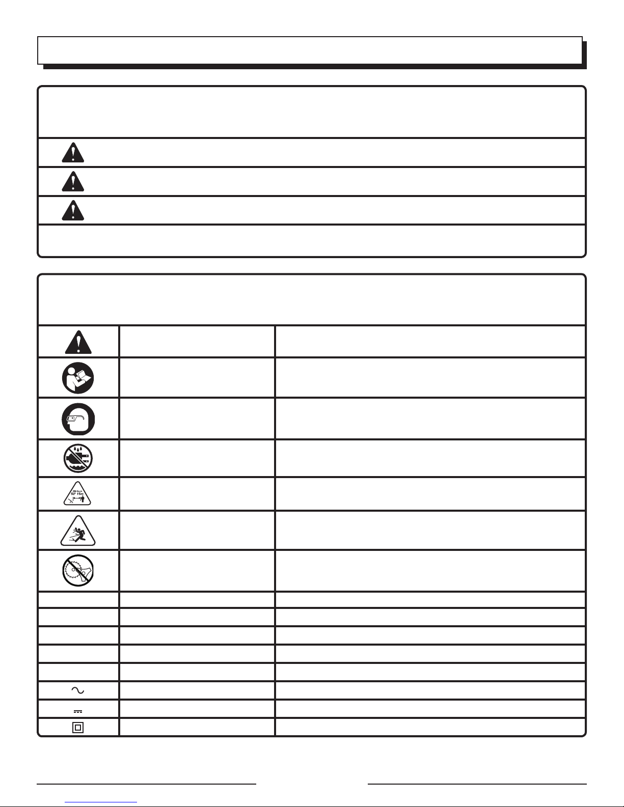
SYMBOLS
The following signal words and meanings are intended to explain the levels of risk associated with this product.
SYMBOL SIGNAL MEANING
DANGER:
WARNING:
CAUTION:
NOTICE:
Some of the following symbols may be used on this product. Please study them and learn their meaning. Proper
interpretation of these symbols will allow you to operate the product better and safer.
SYMBOL
Safety Alert Indicates a potential personal injury hazard.
Read The Operator’s Manual
Eye Protection
NAME
Indicates an imminently hazardous situation, which, if not avoided, will result
in death or serious injury.
Indicates a potentially hazardous situation, which, if not avoided, could result
in death or serious injury.
Indicates a potentially hazardous situation, which, if not avoided, may result in
minor or moderate injury.
(Without Safety Alert Symbol) Indicates important information not related to an
injury hazard, such as a situation that may result in property damage.
DESIGNATION/EXPLANATION
To reduce the risk of injury, user must read and understand
operator’s manual before using this product.
Always wear eye protection with side shields marked to comply
with ANSI Z87.1.
Wet Conditions Alert Do not expose to rain or use in damp locations.
Keep Bystanders Away Keep all bystanders at least 50 ft. away.
Ricochet
No Blade
V Volts Voltage
A Amperes Current
Hz Hertz Frequency (cycles per second)
W Watt Power
min Minutes Time
Alternating Current Type of current
Direct Current Type or a characteristic of current
Class II Tool Double-insulated construction
Thrown objects can ricochet and result in personal injury or
property damage.
Do not install or use any type of blade on a product displaying
this symbol.
Page 5 — English
Page 8
ELECTRICAL
DOUBLE INSULATION
Double insulation is a concept in safety in electric power
tools, which eliminates the need for the usual threewire grounded power cord. All exposed metal parts are
isolated from the internal metal motor components with
protecting insulation. Double insulated tools do not need
to be grounded.
WARNING:
The double insulated system is intended to protect
the user from shock resulting from a break in the tool’s
internal insulation. Observe all normal safety precautions
to avoid electrical shock.
NOTE: Servicing of a product with double insulation requires
extreme care and knowledge of the system and should be
performed only by a qualified service technician. For service,
we suggest you return the tool to your nearest authorized
service center for repair. Always use original factory replacement parts when servicing.
ELECTRICAL CONNECTION
This product has a precision-built electric motor. It should
be connected to a power supply that is 120 volts, AC only
(normal household current), 60 Hz. Do not operate this
product on direct current (DC). A substantial voltage drop
will cause a loss of power and the motor will overheat. If
your product does not operate when plugged into an outlet,
double-check the power supply.
GFCI
Ground Fault Circuit Interrupter (GFCI) protection should be
provided on the circuit(s) or outlet(s) to be used for the product. Receptacles are available having built-in GFCI protection
and may be used for this measure of safety.
EXTENSION CORDS
See Figure 1.
When using a power product at a considerable distance from
a power source, be sure to use an extension cord that has
the capacity to handle the current the product will draw. An
undersized cord will cause a drop in line voltage, resulting in
overheating and loss of power. Use the chart to determine
the minimum wire size required in an extension cord. Only
round jacketed cords listed by Underwriter’s Laboratories
(UL) should be used.
When working outdoors with a product, use an extension
cord that is designed for outside use. This type of cord is
designated with “W-A” or “W” on the cord’s jacket.
Before using any extension cord, inspect it for loose or
exposed wires and cut or worn insulation.
**Ampere rating (on product data plate)
0-2.0 2.1-3.4 3.5-5.0 5.1-7.0 7.1-12.0 12.1-16.0
Cord Length Wire Size (A.W.G.)
25´ 16 16 16 16 14 14
50´ 16 16 16 14 14 12
100´ 16 16 14 12 10 —
**Used on 12 gauge - 20 amp circuit.
NOTE: AWG = American Wire Gauge
WARNING:
Keep the extension cord clear of the working area.
Position the cord so that it will not get caught on lumber,
tools, or other obstructions while you are working with
a power tool. Failure to do so can result in serious personal injury.
WARNING:
Check extension cords before each use. If damaged
replace immediately. Never use product with a damaged
cord since touching the damaged area could cause electrical shock resulting in serious injury.
Page 6 — English
Page 9

FEATURES
FEATURES
Input .......................................................................................................................................120 V, AC only, 60 Hz, 4 Amps
Cutting Swath .................................................................................................................................................................13 in.
Weight .......................................................................................................................................................................5.25 lbs.
KNOW YOUR STRING TRIMMER
See Figure 2.
The safe use of this product requires an understanding of the
information on the product and in this operator’s manual as
well as a knowledge of the project you are attempting. Before
use of this product, familiarize yourself with all operating
features and safety rules.
CORD RETAINER
A convenient cord retainer helps keep the extension cord
connection secure during string trimmer operation.
EDGER GUIDE
The easily mounted edger guide allows the string trimmer
to perform as an edger.
ASSEMBLY
UNPACKING
This product requires assembly.
Carefully remove the product and any accessories from
the box. Make sure that all items listed in the packing list
are included.
FRONT HANDLE
The string trimmer is equipped with a front handle assembly
for ease of operation and to prevent loss of control.
GRASS DEFLECTOR
The trimmer includes a grass deflector that helps protect
from flying debris.
ROTATING REAR HANDLE
The rotating rear handle on the string trimmer can be locked
in two different positions for ease of use when edging.
TELESCOPING SHAFT
The length of the string trimmer can be adjusted for ease
of use.
PACKING LIST
Trimmer Assembly
Front Handle (with hardware)
Grass Deflector (with screws)
Operator’s Manual
WARNING:
Do not use this product if any parts on the Packing List
are already assembled to your product when you unpack
it. Parts on this list are not assembled to the product by
the manufacturer and require customer installation. Use
of a product that may have been improperly assembled
could result in serious personal injury.
Inspect the product carefully to make sure no breakage
or damage occurred during shipping.
Do not discard the packing material until you have carefully
inspected and satisfactorily operated the product.
If any parts are damaged or missing, please call
1-800-242-4672 for assistance.
WARNING:
If any parts are damaged or missing do not operate this
product until the parts are replaced. Use of this product
with damaged or missing parts could result in serious
personal injury.
WARNING:
Do not connect to power supply until assembly is complete. Failure to comply could result in accidental starting
and possible serious personal injury.
WARNING:
Do not attempt to modify this product or create accessories not recommended for use with this product. Any
such alteration or modification is misuse and could result
in a hazardous condition leading to possible serious
personal injury.
Page 7 — English
Page 10
ASSEMBLY
TOOLS NEEDED
See Figure 3.
The following tool (not included) is needed for assembly:
Phillips screwdriver
ATTACHING GRASS DEFLECTOR
See Figures 4 - 5.
WARNING:
The line cut-off blade on the grass deflector is sharp.
Avoid contact with the blade. Failure to avoid contact
can result in serious personal injury.
Remove screws from packet attached to cut-off blade.
Fit the grass deflector into the slots on trimmer head.
OPERATION
WARNING:
Do not allow familiarity with products to make you careless. Remember that a careless fraction of a second is
sufficient to inflict severe injury.
WARNING:
Always wear eye protection with side shields marked to
comply with ANSI Z87.1. Failure to do so could result in
objects being thrown into your eyes, resulting in possible
serious injury.
WARNING:
Never use blades, flailing devices, wire, or rope on this
product. Do not use any attachments or accessories not
recommended by the manufacturer of this product. The
use of attachments or accessories not recommended
can result in serious personal injury.
Before each use, inspect the entire product for damaged,
missing, or loose parts such as screws, nuts, bolts, caps, etc.
Tighten securely all fasteners and caps and do not operate
this product until all missing or damaged parts are replaced.
Please call 1-800-242-4672 or contact an authorized service
center for assistance.
Line up the screw holes in the grass deflector with the
holes in the trimmer head.
Install screws and tighten securely.
ATTACHING THE FRONT HANDLE
See Figure 6.
Loosen and remove the wing nut and bolt from the
handle.
Install the handle on the rear handle pole in the area
indicated by the illustration.
Adjust handle up or down, if necessary, to desired
operating position.
Reinstall the bolt and wing nut. Tighten wing nut to se-
cure.
STARTING/STOPPING THE TRIMMER
See Figure 7.
Attach the outlet end of an extension cord to the plug on
the rear of the string trimmer.
NOTE: Use only approved outdoor extension cords.
Route the extension cord through the slot located on the
rear of the string trimmer housing and place underneath
the cord retainer.
To start the string trimmer, press the switch trigger.
To stop the string trimmer, release the switch trigger.
OPERATING THE TRIMMER
See Figure 8.
Follow these tips when using the string trimmer:
Hold the trimmer with your right hand on the rear handle
and your left hand on the front handle.
Keep a firm grip with both hands while in operation.
Trimmer should be held at a comfortable position with the
rear handle about hip height.
Cut tall grass from the top down. This will prevent grass
from wrapping around the shaft housing and line head
which may cause damage from overheating.
If grass becomes wrapped around the line head:
Stop the trimmer.
Unplug the string trimmer.
Remove the grass.
Page 8 — English
Page 11

OPERATION
WARNING:
Always hold the string trimmer away from the body
keeping clearance between the body and the string
trimmer. Any contact with the string trimmer cutting head
while operating can result in serious personal injury.
ADVANCING LINES
NOTE: The trimmer is equipped with an auto-feed head.
Bumping the head to try to advance the line will damage
trimmer and void warranty.
With the trimmer running, release the switch trigger.
Wait two seconds, and press the switch trigger.
NOTE: The line will extend approximately 1/4 in. with each
stop and start of the switch trigger until the line reaches
the length of the cut-off blade on the grass deflector.
Resume trimming.
ADVANCING THE LINE MANUALLY
Disconnect the string trimmer from the power supply, then
push the spool retainer button in while pulling on trimmer
line to manually advance.
CUT-OFF BLADE
This trimmer is equipped with a cut-off blade on the
grass deflector. For best cutting, advance line until they
are trimmed to length by the cut-off blade. Advance line
whenever you hear the engine running faster than normal,
or when trimming efficiency diminishes. This will maintain
best performance and keep trimmer line long enough to
advance properly.
CUTTING TIPS
See Figure 9.
Keep the trimmer tilted toward the area being cut; this is
the best cutting area.
The string trimmer cuts when passing the unit from right
to left. This will avoid throwing debris at the operator.
Avoid cutting in the dangerous area.
Use the tip of the line to do the cutting; do not force line
head into uncut grass.
Wire and picket fences cause extra line wear, even
breakage. Stone and brick walls, curbs, and wood may
wear trimmer line rapidly.
Avoid trees and shrubs. Tree bark, wood moldings, siding,
and fence posts can easily be damaged by the trimmer
line.
TELESCOPING SHAFT
See Figure 10.
The shaft can be extended or shortened for ease of use.
Unplug the string trimmer.
Unscrew telescoping shaft coupler and slide to desired
position.
Tighten telescoping shaft coupler.
ROTATING REAR HANDLE
See Figure 11.
Unplug the string trimmer.
Pull up edging coupler and turn handle end counterclock-
wise.
Release edging shaft coupler when handle has been
rotated 180° and locks into place.
EDGING
See Figures 12 - 13.
The rotating handle can be used in combination with the
edger guide for edging sidewalks and walkways. To use the
edger guide, flip down from it’s stored position.
Page 9 — English
Page 12
MAINTENANCE
WARNING:
When servicing, use only identical replacement parts.
Use of any other parts can create a hazard or cause
product damage.
WARNING:
Always wear eye protection with side shields marked to
comply with ANSI Z87.1. Failure to do so could result in
objects being thrown into your eyes, resulting in possible
serious injury.
WARNING:
Before inspecting, cleaning, or servicing the machine,
shut off motor, wait for all moving parts to stop, and
disconnect extension cord. Failure to follow these
instructions can result in serious personal injury or
property damage.
GENERAL MAINTENANCE
Before each use, inspect the entire product for damaged,
missing, or loose parts such as screws, nuts, bolts, caps, etc.
Tighten securely all fasteners and caps and do not operate
this product until all missing or damaged parts are replaced.
Please call 1-800-242-4672 or contact an authorized service
center for assistance.
Avoid using solvents when cleaning plastic parts. Most
plastics are susceptible to damage from various types of
commercial solvents and may be damaged by their use. Use
clean cloths to remove dirt, dust, oil, grease, etc.
WARNING:
Do not at any time let brake fluids, gasoline, petroleumbased products, penetrating oils, etc., come in contact
with plastic parts. Chemicals can damage, weaken or
destroy plastic which can result in serious personal injury.
You can often make repairs described here. For other repairs,
have the trimmer serviced by an authorized service dealer.
Periodically, clean all foreign material from the trimmer head
air vents.
SPOOL REPLACEMENT
See Figure 14.
Use only .065 in. diameter monofilament line. Use original
manufacturer’s replacement line for best performance.
Unplug the string trimmer.
Push in tabs on side of spool retainer.
Pull spool retainer up to remove.
Remove spool.
To install the new spool, make sure the two lines are
captured in the slots opposite each other on the new
spool. Make sure the end of each line is extended
approximately 6 in. beyond each slot.
Install the new spool so that the lines and slots align with
the eyelets in the string head. Thread the lines into the
eyelets.
Pull the lines extending from the string head head so the
line releases from the slots in the spool.
Reinstall the spool retainer by depressing tabs into slots
and pushing down until spool retainer clicks into place.
LINE REPLACEMENT
See Figures 14 - 15.
Unplug the string trimmer.
Remove the spool from the string head.
NOTE: Remove any old line remaining on the spool.
Cut two pieces of line, each being approximately
9 ft. (2.7 m) long. Use only .065 in. (1.65 mm) diameter
monofilament line.
Insert the first line into the anchor hole in the upper part
of the spool. Wind the first line around the upper part of
the spool counterclockwise, as shown by the arrows on
the spool. Place line in the slot on upper spool flange,
leaving about 6 in. (152 mm) extended beyond the slot.
Do not overfill. After winding the line, there should be
at least 1/4 in. (6 mm) between the wound line and the
outside edge of the spool.
Repeat above step with second line, using the bottom
part of spool. Do not overfill.
Replace the spool retainer, spool, and the spool retainer.
Refer to Spool Replacement earlier in this manual.
STORING THE TRIMMER
Depress telescoping shaft coupler and set at shortest
setting.
Clean all foreign material from the trimmer.
Store it in a place that is inaccessible to children.
Keep away from corrosive agents such as garden
chemicals and de-icing salts.
Page 10 — English
Page 13

TROUBLESHOOTING
PROBLEM POSSIBLE CAUSE SOLUTION
Lines will not advance when
using the Auto Feed Head:
Grass wraps around driveshaft
housing and string head:
Motor fails to start when
switch trigger is depressed.
CALL
1. Lines are welded to themselves.
2. Not enough line on spool.
3. Lines are worn too short.
4. Lines are tangled on spool.
1. Cutting tall grass at ground level.
1. Power cord is not plugged in or
connection is loose.
2. Household circuit breaker is
tripped.
1. Lubricate with silicone spray.
2. Install more line. Refer to Line Replacement
earlier in this manual.
3. Pull both lines while pressing button.
4. Remove lines from spool and rewind. Refer to
Line Replacement earlier in this manual.
1. Cut tall grass from the top down to prevent
wrapping.
1. Plug in the power cord.
2. Check circuit breaker.
CALL US FIRST
For any questions about operating or maintaining your product,
call the Homelite
Your product has been fully tested prior to shipment to ensure
your complete satisfaction.
®
Help Line!
Page 11 — English
Page 14

WARRANTY
LIMITED WARRANTY STATEMENT
Homelite Consumer Products, Inc., (“Homelite”) warrants
to the original retail purchaser that this HOMELITE brand
outdoor product is free from defect in material and
workmanship and agrees to repair or replace, at Homelite’s,
discretion, any defective product free of charge within these
time periods from the date of purchase.
Two years for all models if used for personal, family, or
household use;
90 days for any unit used for other purposes, such as
rental or commercial.
This warranty extends to the original retail purchaser
only and commences on the date of the original retail
purchase.
Any part of the this product manufactured or supplied
by Homelite and found in the reasonable judgment of
Homelite to be defective in material or workmanship will
be repaired or replaced without charge for parts and labor
by a Homelite authorized service center.
The product, including any defective part, must be returned
to an authorized service dealer within the warranty period.
The expense of delivering the product to the dealer for
warranty work and the expense of returning it back to the
owner after repair or replacement will be paid by the owner.
Homelite’s responsibility in respect to claims is limited to
making the required repairs or replacements and no claim
of breach of warranty shall be cause for cancellation or
rescission of the contract of sale of any HOMELITE brand
product. Proof of purchase will be required by the dealer
to substantiate any warranty claim. All warranty work must
be performed by a Homelite authorized service center.
This warranty is limited to ninety (90) days from the date of
original retail purchase for any HOMELITE brand product
that is used for rental or commercial purposes, or any other
income-producing purpose.
This warranty does not cover any HOMELITE brand product
that has been subject to misuse, neglect, negligence, or
accident, or that has been operated in any way contrary
to the operating instructions as specified in this operator’s
manual. This warranty does not apply to any damage to
the product that is the result of improper maintenance or
to any product that has been altered or modified. The
warranty does not extend to repairs made necessary
by normal wear or by the use of parts or accessories
which are either incompatible with the HOMELITE
brand product or adversely affect its operation,
performance, or durability. In addition, this warranty does
not cover:
A. Tune-ups – Spark Plugs, Carburetor, Carburetor
Adjustments, Ignition, Filters
B. Wear items – Bump Knobs, Outer Spools, Cutting
Lines, Inner Reels, Starter Pulleys, Starter Ropes, Drive
Belts, Tines, Felt Washers, Hitch Pins, Mulching Blades,
Blower Fans, Blower and Vacuum Tubes, Vacuum Bags
and Straps, Guide Bars, Saw Chains
Homelite reserves the right to change or improve
the design of any HOMELITE brand product without
assuming any obligation to modify any product previously
manufactured.
ALL IMPLIED WARRANTIES ARE LIMITED IN DURATION
TO THE STATED WARRANTY PERIOD. ACCORDINGLY,
ANY SUCH IMPLIED WARRANTIES INCLUDING
MERCHANTABILITY, FITNESS FOR A PARTICULAR
PURPOSE, OR OTHERWISE, ARE DISCLAIMED IN
THEIR ENTIRETY AFTER THE EXPIRATION OF THE
APPROPRIATE TWO-YEAR, OR NINETY-DAY WARRANTY
PERIOD. HOMELITE’S OBLIGATION UNDER THIS
WARRANTY IS STRICTLY AND EXCLUSIVELY LIMITED
TO THE REPAIR OR REPLACEMENT OF DEFECTIVE
PARTS AND HOMELITE DOES NOT ASSUME OR
AUTHORIZE ANYONE TO ASSUME FOR THEM ANY
OTHER OBLIGATION. SOME STATES DO NOT ALLOW
LIMITATIONS ON HOW LONG AN IMPLIED WARRANTY
LASTS, SO THE ABOVE LIMITATION MAY NOT APPLY
TO YOU. HOMELITE ASSUMES NO RESPONSIBILITY
FOR INCIDENTAL, CONSEQUENTIAL, OR OTHER
DAMAGES INCLUDING, BUT NOT LIMITED TO, EXPENSE
OF RETURNING THE PRODUCT TO AN AUTHORIZED
HOMELITE SERVICE CENTER AND EXPENSE OF
DELIVERING IT BACK TO THE OWNER, MECHANIC’S
TRAVEL TIME, TELEPHONE OR TELEGRAM CHARGES,
RENTAL OF A LIKE PRODUCT DURING THE TIME
WARRANTY SERVICE IS BEING PERFORMED, TRAVEL,
LOSS OR DAMAGE TO PERSONAL PROPERTY, LOSS
OF REVENUE, LOSS OF USE OF THE PRODUCT, LOSS
OF TIME, OR INCONVENIENCE. SOME STATES DO NOT
ALLOW THE EXCLUSION OR LIMITATION OF INCIDENTAL
OR CONSEQUENTIAL DAMAGES, SO THE ABOVE
LIMITATION OR EXCLUSION MAY NOT APPLY TO YOU.
This warranty gives you specific legal rights, and you may
also have other rights which vary from state to state.
This warranty applies to all HOMELITE brand products
manufactured by or for Homelite and sold in the United
States and Canada.
To locate your nearest Homelite authorized service
center, dial 1-800-242-4672 or log on to our website at
www.homelite.com.
Page 12 — English
Page 15

NOTES
Page 13
Page 16

INSTRUCTIONS IMPORTANTES CONCERNANT LA SÉCURITÉ
AVERTISSEMENT :
Lire et veiller à bien comprendre toutes les
instructions. Le non-respect des instructions ci-dessous
peut entraîner une électrocution, un incendie et des
blessures graves.
LIRE TOUTES LES INSTRUCTIONS
Pour travailler en toute sécurité, lire et veiller à bien
comprendre toutes les instructions avant d’utiliser
ce produit. Respecter toutes les instructions de
sécurité. Le non respect des instructions de sécurité
ci-dessous peut entraîner des blessures graves.
Ne pas laisser des enfants ou personnes n’ayant pas reçu
une formation adéquate utiliser cet outil.
Déblayer la zone de travail avant chaque utilisation. La
débarrasser de tous les objets tels que cailloux, verre brisé,
clous, fils métalliques, cordes, etc. risquant d’être projetés
ou de se prendre dans la ligne de coupe ou la lame.
Toujours porter une protection oculaire avec écrans
latéraux certifiée conforme à la norme ANSI Z87.1.
Utiliser les lunettes de sûreté – Toujours la visage
d’usage ou le masque de poussière si l’opération est
poussiéreuse.
Vêtements adéquats –Le port de gants de caoutchouc et
de chaussures solides est recommandé pour le travail à
l’extérieur. Porter des pantalons et des manches longues
en tissu robuste, des chaussures de travail et des gants.
Ne pas porter de vêtements amples, des bijoux ou tout
autre article pouvant se coincer dans les pièces mobiles.
Attacher les cheveux longs pour les maintenir au-dessus
des épaules afin qu’ils ne se coincent pas dans les pièces
mobiles.
Ne pas porter de vêtements amples, bijoux, shorts,
sandales et ne pas travailler pieds nus.
Tenir les enfants éloignés - Ranger les appareils qui ne
sont pas utilisés - Garder les badauds, enfants et animaux
à une distance de 15 m (50 pi) minimum.
Rester alerte - Ne pas utiliser ce taille-bordures en état de
fatigue, si l’on est souffrant ou sous l’influence de l’alcool,
de drogues ou de médicaments.
Ne pas fonctionner dans les pauvres allumant.
Garder toutes les parties du corps à l’écart des pièces
en mouvement.
Ne pas utiliser d’outils électriques dans des atmosphères
explosives, par exemple en présence de liquides, gaz
ou poussières inflammables. Les outils électriques
produisent des étincelles risquant d’enflammer les
poussières ou vapeurs.
Pour éviter les risques de choc électrique, cet outil est
équipé d’une fiche polarisée (une broche est plus large
que l’autre) qui exige l’usage d’un cordon polarisé. Cette
fiche ne peut être branchée sur une prise polarisée que
dans un sens. Si la fiche ne peut pas être insérée dans la
prise du cordon, l’inverser. Si la fiche ne peut toujours pas
être insérée, se procurer un cordon polarisé approprié.
Une rallonge polarisée exigera l’utilisation d’une prise de
courant murale polarisée. Cette fiche ne peut être branchée
dans une prise polarisée que dans un sens. Si la fiche ne
peut pas être insérée à fond dans la prise, l’inverser. Si elle
ne peut toujours pas être insérée, faire installer une prise
adéquate par un électricien qualifié. Ne jamais modifier la
fiche de l’outil, ni la prise ou la fiche du cordon prolongateur.
Éviter tout contact du corps avec des surfaces mises
à la terre,
réfrigérateurs. Le risque de choc électrique est accru
lorsque le corps est mis à la terre.
Éviter les environnements dangereux - Ne pas exposer les
outils électriques à la pluie ou l’humidité. La pénétration
d’eau dans ces outils accroît le risque de choc électrique.
AVERTISSEMENT ! – Pour réduire le risque d’un choc
électrique W-A, W,
SJTW-A, ou SJTOW-A.
l’usage en extérieur et réduisent les risques de choc
électrique.
Des disjoncteurs de fuite à la terre utilisés devraient être
installés sur les circuits ou les prises utilisées avec les outils de jardinage. Des réceptacles avec disjoncteur de fuite
à la terre sont disponibles et peuvent être utilisés afin de
respecter cette mesure de sécurité.
Utiliser l’outil approprié - Ne pas forcer l’outil. Utiliser
un outil approprié pour le travail. Un outil approprié
exécutera le travail mieux et de façon moins dangereuse
s’il fonctionne dans les limites prévues.
Ne pas faire fonctionner l’équipement pied-nu ou
en portant des sandales ou des chaussures légères
similaires. Porter des chaussures de protection qui
protègent vos pieds et améliorent votre équilibre sur des
surfaces glissantes.
Ne pas exagérer en se courbant ou en s’étirant. Se tenir
bien campé et en équilibre. Ne pas travailler hors de
portée de l’outil.
Éviter une mise en marche accidentelle –
démarrages accidentels. S’assurer que la gâchette du
commutateur n’est pas engagée avant de brancher l’outil.
Ne pas utiliser l’outil si le commutateur ne permet pas de
le mettre en marche et de l’arrêter. Tout outil qui ne peut
pas être contrôlé par son commutateur est dangereux et
doit être réparé.
Débranchement de l’outil – Débrancher le taille-bordures
de la source d’alimentation avant de le ranger, le réparer,
changer les accessoires, comme le fil, et dès la fin de
l’utilisation. Ces mesures de sécurité réduisent les risques
de démarrage accidentel de l’outil.
Utiliser exclusivement des pièces de rechange et
accessoire d’origine. L’usage de toute autre pièce pourrait
créer une situation dangereuse ou endommager l’outil.
Page 3 — Français
telles que tuyaux, radiateurs, cuisinières et
Utiliser des cordons prolongateurs marqués
SW-A, SOW-A, STW-A, STOW-A, SJW-A,
Ces cordons sont conçus pour
Éviter les
Page 17

INSTRUCTIONS IMPORTANTES CONCERNANT LA SÉCURITÉ
Garder l’outil en bon état – Remplacer la bobine si elle
est fissurée, écaillée ou endommagée de quelconque
façon. S’assurer que la tête de coupe est installée et
fixée correctement et fermement. Ne pas prendre cette
précaution représente des risques de blessures graves.
Suivre les instructions de lubrification et de changement
d’accessoires. Inspecter périodiquement le cordon
d’alimentation. Si celui-ci est endommagé, le faire réparer
par un centre de service autorisé. Inspecter périodiquement les rallonges et les remplacer si elles sont endommagées. Garder l’outil sec, propre et exempt d’huile ou
de graisse.
S’assurer que tous les dispositifs de protection,
déflecteurs et poignées sont correctement installés et
solidement assujettis.
Utiliser exclusivement des lignes de coupe d’origine.
Ne pas utiliser un autre accessoire de coupe, tel que fil
métallique, corde, ou autre. L’utilisation d’une tête de
coupe d’autre marque sur cette taille-bordures à ligne
peut entraîner des blessures graves.
Ne jamais utiliser l’outil si le déflecteur d’herbe n’est pas
en place et en bon état.
Vérifier les pièces endommagées. Quand un protecteur
ou une autre pièce a été endommagé(e), vérifier, avant
de continuer à utiliser l’outil, si cette pièce pourra encore
fonctionner normalement et remplir son rôle. Vérifier
l’alignement des pièces mobiles, détecter les pièces
mobiles grippées ou les pièces rompues, un assemblage
déficient ou toute autre condition pouvant affecter la
sécurité d’utilisation. Un protecteur ou une autre pièce
endommagé(e) doit être réparé convenablement ou
remplacé par un centre d’entretien agréé afin d’éviter
des blessures corporelles.
Tenir fermement les deux poignées pendant le travail.
Tenir la tête de coupe au-dessous du niveau de la taille.
Ne jamais tailler avec la tête de coupe à plus de 762 mm
(30 po) du sol.
Ranger les appareils qui ne sont pas utilisés - Quand
pas dans l’usage, taille-bordures à ligne devrait être
emmagasiné à la maison dans un sec, fermé à clef la
remiser dans un endroit inaccessible aux enfants.
Cordon prolongateur - S’assurer que le cordon
prolongateur est en bon état. Si un cordon prolongateur
est utilisé, s’assurer que sa capacité est suffisante pour
supporter le courant de fonctionnement de l’outil. Un
calibre de fil (A.W.G) d’au minimum 16 est recommandé
pour un cordon prolongateur de 15 mètres (50 pi)
maximum. En cas de doute, utiliser un cordon du calibre
immédiatement supérieur. Moins le numéro de calibre est
élevé, plus la capacité du fil est grande. Un cordon de
capacité insuffisante causerait une baisse de la tension
de ligne, entraînant une perte de puissance et une
surchauffe.
Nouer le cordon et la rallonge, comme montré à la figure
1, afin réduire le risque de débranchement de ces derniers.
Ne jamais utiliser de lames ou de dispositifs à fléau.
L’unité est conçue pour être utilisée exclusivement avec
un taille bordures à fil. Le fait d’utiliser l’outil avec tout
autre accessoire ou dispositif fait augmenter le risque de
blessures.
Examiner la surface à tondre. Retirer tous les objets
(roches, verre brisé, clous, câble, corde etc.) qui peuvent
être projetés dans les airs ou qui peuvent s’emmêler dans
la tête de coupe.
S’assurer que les évents d’aération sont propres et
exempts de débris afin d’éviter que le moteur ne
surchauffe. Les nettoyer après chaque utilisation.
Arrêter l’outil et le débrancher de la source d’alimentation
lorsqu’il n’est pas utilisé. Attendre l’arrêt complet du
moteur avant de déplacer l’outil.
Ranger l’outil en s’assurant qu’il est débranché et qu’il
est hors de la portée des enfants.
Ne pas suspendre l’outil d’une façon qui enclencherait
la gâchette.
Ne pas utiliser plus d’un cordon.
Éviter de malmener le cordon. Ne jamais transporter
l’outil en le tenant par le cordon, ou tirer d’un coup sec
sur celui-ci pour débrancher l’outil.
Tenir le cordon loin de l’utilisateur et des obstacles en tout
temps. Ne pas exposer le cordon à la chaleur, à l’huile,
à l’eau ou à des arêtes tranchantes.
Garder le cordon à l’écart de la chaleur, de l’huile et des
arêtes tranchantes.
Si le cordon d’alimentation est endommagé, il doit être
remplacé uniquement pas le fabricant ou par un centre
de réparation agréé pour éviter tout risque.
Conserver ces instructions. Les consulter fréquemment et
les utiliser pour instruire les autres utilisateurs éventuels.
Si cet outil est prêté, il doit être accompagné de ces
instructions.
Page 4 — Français
Page 18

SYMBOLES
Les termes de mise en garde suivants et leur signification ont pour but d’expliquer le degré de risques associé à l’utilisation
de ce produit.
SYMBOLE SIGNAL SIGNIFICATION
DANGER :
AVERTISSEMENT :
ATTENTION :
AVIS :
Certains des symboles ci-dessous peuvent être utilisés sur produit. Veiller à les étudier et à apprendre leur signification.
Une interprétation correcte de ces symboles permettra d’utiliser produit plus efficacement et de réduire les risques.
Indique une situation extrêmement dangereuse qui, si elle n’est pas évitée,
aura pour conséquences des blessures graves ou mortelles.
Indique une situation potentiellement dangereuse qui, si elle n’est pas évitée,
pourrait entraîner des blessures graves ou mortelles.
Indique une situation potentiellement dangereuse qui, si elle n’est pas évitée,
pourraît entraîner des blessures légères ou de gravité modérée.
(Sans symbole d’alerte de sécurité) Indique une information importante
ne concernant pas un risque de blessure comme une situation pouvant
occasionner des dommages matériels.
SYMBOLE NOM DÉSIGNATION / EXPLICATION
Symbole d’alerte de sécurité Indique un risque de blessure potentiel.
Pour réduire les risques de blessures, l’utilisateur doit lire et
Lire le manuel d’utilisation
Protection oculaire
veiller à bien comprendre le manuel d’utilisation avant d’utiliser
ce produit.
Toujours porter une protection oculaire avec écrans latéraux
certifiée conforme à la norme ANSI Z87.1.
Avertissement concernant
l’humidité
Ne laisser personne
s’approcher
Danger de ricochet
Ne pas utiliser de lame
V Volts Tension
A Ampères Intensité
Hz Hertz Fréquence (cycles par seconde)
W Watts Puissance
min Minutes Temps
Courant alternatif Type de courant
Courant continu Type ou caractéristique du courant
Outil de la classe II Construction à double isolation
Ne pas exposer à la pluie ou l’humidité.
Garder les badauds à une distance de 15 m (50 pi) minimum.
Ne pas utiliser le coupe-bourdures sans le protecteur. Rester
éloigné de la tête de coupe rotative.
Ne jamais utiliser une lame quelconque sur un outil portant ce
symbole.
Page 5 — Français
Page 19

CARACTÉRISTIQUES ÉLECTRIQUES
DOUBLE ISOLATION
La double isolation est un dispositif de sécurité utilisé sur les
outils à moteur électriques, éliminant le besoin de cordon
d’alimentation habituel à trois fils avec terre. Toutes les
pièces métalliques exposées sont isolées des composants
internes du moteur par l’isolation protectrice. Les produits à
double isolation ne nécessitent pas de mise à la terre.
AVERTISSEMENT :
Le système à double isolation est conçu pour protéger
l’utilisateur contre les chocs électriques causés par une
rupture de l’isolation interne de l’outil. Prendre toutes les
précautions de sécurité normales pour éviter les chocs
électriques.
NOTE : La réparation d’un produit à double isolation exigeant
des précautions extrêmes ainsi que la connaissance du
système, elle ne doit être confiée qu’à un réparateur qualifié.
En ce qui concerne les réparations, nous recommandons
de confier l’produit au centre de réparation le plus proche.
Utiliser exclusivement des pièces d’origine pour les
réparations.
CONNEXIONS ÉLECTRIQUES
Cet produit est équipé d’un moteur électrique de précision.
Elle doit être branchée uniquement sur une alimentation
120 V, c.a. (courant résidentiel standard), 60 Hz. Ne pas
utiliser cet produit sur une source de courant continu (c.c.).
Une chute de tension importante causerait une perte de puissance et une surchauffe du moteur. Si l’produit ne fonctionne
pas une fois branché, vérifier l’alimentation électrique.
GFCI
Les circuits et prises sur lesquels cet produit est branché
doivent être protégés par un disjoncteur différentiel. Des
prises à disjoncteur différentiel sont en vente dans le commerce et peuvent être utilisées à titre de sécurité.
Pour le travail à l’extérieur, utiliser un cordon prolongateur
spécialement conçu à cet effet. Ce type de cordon porte
l’inscription « W-A » ou « W » sur sa gaine.
Avant d’utiliser un cordon prolongateur, vérifier que ses fils
ne sont ni détachés ni exposés et que son isolation n’est ni
coupée, ni usée.
**Intensité nominale (sur la plaquette signalétique de l’produit)
0-2,0 2,1-3,4 3,5-5,0 5,1-7,0 7,1-12,0 12,1-16,0
Longueur du Calibre de fil
cordon (A.W.G.)
25´ 16 16 16 16 14 14
50´ 16 16 16 14 14 12
100´ 16 16 14 12 10 —
**Utilisé sur circuit de calibre 12 – 20 A
NOTE : AWG = American Wire Gauge
AVERTISSEMENT :
Maintenir le cordon prolongateur à l’écart de la zone de
travail. Lors du travail avec un cordon électrique, placer le
cordon de manière à ce qu’il ne risque pas de se prendre
dans les pièces de bois, produits et autres obstacles. Ne
pas prendre cette précaution peut entraîner des blessures
graves.
AVERTISSEMENT :
Vérifier l’état des cordons prolongateurs avant chaque
utilisation. Remplacer immédiatement tout cordon
endommagé. Ne jamais utiliser un produit dont le cordon
d’alimentation est endommagé, car tout contact avec la
partie endommagée pourrait causer un choc électrique
et des blessures graves.
CORDONS PROLONGATEURS
Voir la figure 1.
Lors de l’utilisation d’un produit électrique à grande distance
d’une prise secteur, veiller à utiliser un cordon prolongateur
d’une capacité suffisante pour supporter l’appel de courant
de l’produit. Un cordon de capacité insuffisante causerait
une baisse de la tension de ligne, entraînant une perte de
puissance et une surchauffe. Se reporter au tableau cidessous pour déterminer le calibre minimum de fil requis
pour un cordon donné. Utiliser exclusivement des cordons à
gaine cylindrique homologués par Underwriter’s Laboratories
(UL).
Page 6 — Français
Page 20

CARACTÉRISTIQUES
CARACTÉRISTIQUES
Alimentation........................................................................................................................120 V, c.a. seulement, 60 Hz, 4 A
Largeur de coupe ...................................................................................................................................... 330,2 mm (13 po)
Poids ...............................................................................................................................................................2,4 kg (5,25 lb)
VEILLER À BIEN CONNAÎTRE LA TAILLEBORDURES À LIGNE
Voir la figure 2.
L’utilisation sûre de ce produit exige une compréhension
des renseignements figurant sur l’produit et contenus dans
le manuel d’utilisation, ainsi qu’une bonne connaissance du
projet entrepris. Avant d’utiliser ce produit, se familiariser
avec toutes ses caractéristiques et règles de sécurité.
RETENUE DE CORDON
Une retenue de cordon pratique contribue au maintien en
toute sécurité de la connexion du cordon prolongateur lors
du fonctionnement de la taille-bordures à ligne.
GUIDAGE DU TAILLE -BORDURE
La bordure à installation facile permet à la taille-bordures à
ligne d’être utilisé comme un taille-bordure.
ASSEMBLAGE
DÉBALLAGE
Ce produit doit être assemblé.
Sortir avec précaution l’produit et les accessoires de la
boîte. S’assurer que toutes les pièces figurant sur la liste
de contrôle sont incluses.
AVERTISSEMENT :
Ne pas utiliser le produit si, en le déballant, vous
constatez que des éléments figurant dans la liste de
contrôle d’expédition sont déjà assemblés. Certaines
pièces figurant sur cette liste n’ont pas été assemblées
par le fabricant et exigent une installation. Le fait d’utiliser
un produit qui a été assemblé de façon inadéquate peut
entraîner des blessures.
POIGNÉE AVANT
La taille-bordures à ligne est équipée d’une poignée avant
pour une utilisation aisée et pour éviter toute perte de
contrôle.
DÉFLECTEUR D’HERBE
La taille-bordures à ligne est équipée d’un déflecteur d’herbe
qui protège l’opérateur des débris projetés.
POIGNÉE ARRIèRE ROTATIVE
La poignée arrière rotative peut être verrouillée en deux
positions différentespour faciliter l’utilisationlors de la taille
de bordures.
FLèCHE TÉLESCOPIQUE
Il est possible de règler la longueur du taille-bordures pour
en faciliter l’utilication.
LISTE DE CONTRÔLE
Taille-bordures à ligne
Poignée avant (avec quincaillerie)
Déflecteur d’herbe (avec vis)
Manuel d’utilisation
AVERTISSEMENT :
Si des pièces sont manquantes ou endommagées, ne pas
utiliser cet produit sans les avoir préalablement remplacées. Le fait d’utiliser ce produit même s’il contient des
pièces endommagées ou s’il lui manque des pièces peut
entraîner des blessures graves.
Examiner soigneusement l’produit pour s’assurer que
rien n’a été brisé ou endommagé en cours de transport.
Ne pas jeter les matériaux d’emballage avant d’avoir
soigneusement examiné l’produit et d’avoir vérifié qu’il
fonctionne correctement.
Si des pièces sont manquantes ou endommagées,
appeler le 1-800-242-4672.
AVERTISSEMENT :
Ne pas brancher sur le secteur avant d’avoir terminé
l’assemblage. Le non-respect de cet avertissement peut
causer un démarrage accidentel, entraînant des blessures graves.
Page 7 — Français
Page 21

ASSEMBLAGE
AVERTISSEMENT :
Ne pas essayer de modifier cet produit ou de créer
des accessoires non recommandés pour cet produit.
De telles altérations ou modifications sont considérées
comme un usage abusif et peuvent créer des conditions
dangereuses pouvant entraîner des blessures graves.
OUTILS NÉCESSAIRES
Voir la figure 3.
La outil suivants (non inclus) si nécessaires pour l’assemblage :
Tournevis à pointe cruciforme
FIXATION DU DÉFLECTEUR D’HERBE
Voir les figures 4 et 5.
AVERTISSEMENT :
La lame coupe ligne du déflecteur est tranchante. Éviter
de la toucher. Le contact avec la lame peut causer des
blessures graves.
Retirez les vis du sachet attaché pour couper la lame.
Adapter le déflecteurd’herbe dans les fentes de la tête
de la taille-bordures à ligne.
Aligner les trous du déflecteur d’herbe avec le trou central
de la tête de la taille-bordures à ligne.
Installer la vis et la serrer solidement.
INSTALLATION DE LA POIGNÉE AVANT
Voir la figure 6.
Desserrer et retirer l’écrou à oreilles, la rondelle et la
ceinture de la poignée.
Installer la poignée sur l’arbre de la poignée arrière dans
l’espace indiqué sur la figure.
Ajuster la poignée vers le haut ou vers le bas, si
nécessaire, à la position d’opération désirée.
Réinstaller le boulon et l’écrou à oreilles. Serrer l’écrou à
oreilles de manière à le fixer solidement.
UTILISATION
AVERTISSEMENT :
Ne pas laisser la familiarité avec les produits faire oublier
la prudence. Ne pas oublier qu’une fraction de seconde
d’inattention peut entraîner des blessures graves.
AVERTISSEMENT :
Toujours porter une protection oculaire certifiée conforme
à la norme ANSI Z87.1. Si cette précaution n’est pas
prise, des objets peuvent être projetés dans les yeux et
causer des lésions graves.
AVERTISSEMENT :
Ne jamais utiliser de lames ou de dispositifs à fléau, fil
et cordes sur ce produit. Ne pas utiliser d’produits ou
accessoires non recommandés par le fabricant pour
cet produit. L’utilisation de pièces et accessoires non
recommandés peut entraîner des blessures graves.
les pièces manquantes ou endommagées n’ont pas été
remplacées. Veuillez composer le 1- 800- 242- 4672 ou
communiquer avec un centre de réparations agréé pour
obtenir de l’aide.
MISE EN MARCHE ET ARRÊT DE LA
TAILLE-BORDURES À LIGNE
Voir la figure 7.
Insérer la fiche d’un cordon prolongateur dans la prise à
l’arrière de la taille-bordures à ligne.
NOTE : N’utiliser que des cordons prolongateurs
homologués pour une utilisation en plein air.
Acheminer le cordon prolongateur par le entaille située à
l’arrière du carter de la taille-bordures à ligne et le placer
sous la retenue de cordon.
Pour mettre la taille-bordures à ligne en marche, appuyer
la gâchette.
Pour arrêter la taille-bordures à ligne, relâcher la gâchette.
Avant chaque utilisation, inspecter au complet le produit
afin de s’assurer qu’aucune pièce (vis, écrous, boulons,
chapeaux, etc.) n’est endommagée, manquante ou
desserrée. Serrer solidement toutes les pièces de fixation
et les chapeaux et ne pas utiliser le produit tant que toutes
Page 8 — Français
Page 22

UTILISATION
UTILISATION DE LA TAILLE-BORDURES
Voir la figure 8.
Suivre ces conseils lors de l’utilisation de la taillebordures à ligne :
Tenir la taille-bordures à ligne avec la main droite sur la
poignée arrière et la main gauche sur la poignée avant.
Garder une prise ferme sur les deux poignées pendant
le fonctionnement.
Maintenir la taille-bordures à ligne dans une position
confortable, la poignée arrière à peu près à hauteur de
la taille.
Couper les herbes hautes de haut en bas. Ceci empêchera l’herbe de s’enrouler sur le tube de l’arbre moteur et
la tête de coupe, ce qui pourrait causer des dommages
dus à une surchauffe.
Si l’herbe s’enroule autour de la tête de coupe :
Arrêter la taille-bordures.
Débrancher la taille-bordures à ligne.
Éliminer l’herbe.
AVERTISSEMENT :
Toujours tenir la taille-bordures à ligne distance de soi
en maintenant un périmètre de sécurité entre le corps
et la taille-bordures à ligne. Tout contact avec la tête de
coupe de la taille-bordures à ligne en cours d’utilisation
peut causer des blessures graves.
AVANCE DU FILS DE COUPE
NOTE : La taille-bordures à ligne est équipé avec une tête
d’auto-nourrit. Frapper la tête pour essayer d’avancer la ligne
endommagera la garantie plus mince et vide.
La taille-bordures à ligne en marche, faire tourner le moteur
à plein régime.
Attendre deux secondes puis appuyer sur la gâchette.
NOTE : Le fil avancera d’environ 6,3 mm (1/4 po) à chaque
relâchement et pesée de la gâchette jusqu’à ce que la
longueur du fil atteigne la lame de coupe du déflecteur
d’herbe.
Continuer le travail.
AVANCE MANUELLE DU FILS
Débrancher la taille-bordures à ligne et enfoncer la la retenue
de bobine et tirer sur le ou le fils les tirer manuellement.
LAME COUPE-LIGNE
Cette taille-bordures à ligne est équipée d’une lame coupeligne montée sur le déflecteur d’herbe. Pour obtenir une
coupe optimale, faire progresser les fils jusqu’à ce qu’il soit
coupé à la longueur correcte par la lame coupe-ligne. Les
fils doit être avancé chaque fois que le moteur tourne à une
vitesse supérieure à la normale ou lorsque la coupe devient
moins efficace. Ceci permet de maintenir une efficacité
maximum et de maintenir une longueur de fils suffisante
pour avancer correctement.
CONSEILS
Voir la figure 9.
Pour une efficacité maximum, garder la taille-bordures à
ligne inclinée vers la zone de coupe.
La taille-bordures à ligne coupe lors du passage de l’unité
de droite à gauche. Ceci évite que les débris soient projetés en direction de l’opérateur.
Couper avec l’extrémité du fil ; ne pas forcer la tête de
coupe dans l’herbe non coupée.
Les palissades en métal et en bois accélèrent l’usure du fil
et peuvent le casser. Les murs en pierre et brique, trottoirs
et pièces de bois peuvent accélérer l’usure du fils.
Contourner les arbres et buissons. L’écorce des arbres,
les moulures en bois, le lambrissage et les piquets de
palissades peuvent être endommagés par les fils.
FLèCHE TÉLESCOPIQUE
Voir la figure 10.
La flèche peut être déployée ou rétractée pour en faciliter
l’utilisation.
Débrancher la taille-bordures à ligne.
Devisser le bouton de la flèche télescopique et la faire
glisser sur la position souhaitée.
Serrer le bouton de la flèche télescopique.
POIGNÉE ARRIèRE
Voir la figure 11.
Débrancher la taille-bordures à ligne.
Tirer en haut le bouton du taille-bordure vers le haut et
tourner la poignée dans le sens anti-horaire.
Deserrer bouton de taille-bordure quand la poignée a été
tournée 180° et se verrouille en place.
TAILLE DES BORDURES
Voir les figures 12 et 13.
La poignée rotative peut être utilisée en combinaison avec la
guidage du taille-bordure pour tailler la bordure des trottoirs
et des allées. Pour utiliser le guidage du taille-bordure, la
chiquenaude en bas de lui a emmagasiné la position.
Page 9 — Français
Page 23

ENTRETIEN
AVERTISSEMENT :
Utiliser exclusivement des pièces identiques à celles
d’origine pour les réparations. L’utilisation de toute
autre pièce pourrait créer une situation dangereuse ou
endommager l’produit.
AVERTISSEMENT :
Toujours porter une protection oculaire certifiée conforme
à la norme ANSI Z87.1. Si cette précaution n’est pas
prise, des objets peuvent être projetés dans les yeux et
causer des lésions graves.
AVERTISSEMENT :
Avant d’inspecter, de nettoyer ou d’entretenir la machine,
arrêter le moteur, attendre l’arrêt de toutes les pièces
en mouvement et débrancher le cordon prolongateur.
Le non-respect de ces instructions peut entraîner des
blessures graves ou des dégâts matériels.
ENTRETIEN GÉNÉRAL
Avant chaque utilisation, inspecter au complet le produit
afin de s’assurer qu’aucune pièce (vis, écrous, boulons,
chapeaux, etc.) n’est endommagée, manquante ou
desserrée. Serrer solidement toutes les pièces de fixation
et les chapeaux et ne pas utiliser le produit tant que toutes
les pièces manquantes ou endommagées n’ont pas été
remplacées. Veuillez composer le 1- 800- 242- 4672 ou
communiquer avec un centre de réparations agréé pour
obtenir de l’aide.
Éviter d’utiliser des solvants pour le nettoyage des pièces en
plastique. La plupart des matières plastiques peuvent être
endommagées par divers types de solvants commerciaux.
Utiliser un chiffon propre pour éliminer la saleté, la poussière,
l’huile, la graisse, etc.
AVERTISSEMENT :
Ne jamais laisser de liquides tels que le
liquide de frein, l’essence, les produits à base
de pétrole, les huiles pénétrantes, etc., entrer en
contact avec les pièces en plastique. Les produits
chimiques peuvent endommager, affaiblir ou
détruire le plastique, ce qui peut entraîner des blessures
graves.
Les réparations décrites ci-dessous peuvent être effectuées
par l’utilisateur. Les autres réparations doivent être confiées
à un centre de réparations agréé.
Périodiquement, nettoyez tout le matériel étranger des
évents d’aération.
REMPLACEMENT DE LA BOBINE
Voir la Figure 15.
Utiliser uniquement un fil à un filament de 1,65 mm
(0,065 po) de diamètre. Pour une efficacité maximum, utiliser
exclusivement un fil d’origine.
Débrancher la taille-bordures à ligne.
Enfoncer les languettes sur le côté de la retenue de
bobine.
Force la retenue de bobine vers le haut, pour la
retirer.
Retirer la tête de coupe.
Lors de l’installation d’une bobine neuve, s’assurer
que les deux fils sont engagés dans les deux
fentes diamétralement opposées de la bobine neuve.
Veiller à ce que les deux fils dépassent chaque fente
d’environ 15 cm (6 po).
Installer la nouvelle bobine de sorte que le fils et les fentes
soient alignés avec l’oeillets le plus proche de la tête de
coupe. Passer les fils dans les œillet de la tête de coupe.
Force les fils étendre de la tête de coupe si le fil les
relâchements de les fentes ce la tête de coupe.
Réinstaller la retenue de bobine en insérant les languettes
dans les fentes et en enfonçant jusqu’à ce que la retenue
de bobine s’insère en place.
REMPLACEMENT DU FIL
Voir les figures 15 et 16.
Débrancher la taille-bordures à ligne.
Retirer la bobine de la tête de coupe.
NOTE : Retirer le fil restant éventuellement sur la bobine.
Couper deux morceaux de fil d’environ 2,7 m (9 pi).Utiliser
uniquement un fil à un filament de 1,65 mm (0,065 po)
de diamètre.
Insérer le premier fil dans le trou d’ancrage de la partie
supérieure de la bobine. Enrouler le fil sur la partie
supérieure de la bobine dans le sens anti-horaire, comme
indiqué par les flèches de la bobine. Engager le fil dans
la fente du flasque supérieur en le laissant dépasser
d’environ 15 cm (6 po) au-delà de la fente. Ne pas trop
remplir. Une fois le fil enroulé, il doit se trouver à au moins
6 mm (1/4 po) du bord de la bobine.
Répéter l’opération ci-dessus en enroulant le seconde
fil sur la partie inférieure de la bobine. Ne pas trop
remplir.
Remettre la retenue en plastique, la bobine et sa retenue
en place. Voir Remplacement de la bobine plus haut
dans ce manuel.
REMISAGE DE LA TAILLE-BORDURES À LIGNE
Enfoncer le bouton de la flèche télescopique et la faire
glisser sur la position la plus courte.
Nettoyer soigneusement la taille-bordures à ligne.
La remiser dans un endroit inaccessible aux enfants.
Le tenir à l’écart de produits corrosifs, tels que les produits
chimiques de jardinage et le sel de dégivrage.
Page 10 — Français
Page 24

DÉPANNAGE
PROBLèME CAUSE POSSIBLE SOLUTION
Les lignes n’avance
pas :
L’herbe s’enroule sur le
tube de l’arbre moteur et
la tête de coupe :
Le moteur ne démarre
pas.
BESOIN D’AIDE?
1-800-242-4672
1. Lignes soudée sur ellemême.
2. Pas assez de lignes sur la
bobine.
3. Lignes trop courte.
4. Lignes emmêlée sur la
bobine.
1. Coupe de hautes herbes au
ras du sol.
1. Le cordon d’alimentation
n’est pas branché ou la connexion est desserrée.
2. Disjoncteur de la résidence
déclenché.
NOUS APPELER D’ABORD
Pour toute question concernant l’utilisation ou l’entretien utiliser ce
produit , appeler le service d’assistance téléphonique Homelite®!
La taille-bordures à ligne a été entièrement testée avant expédition
pour assurer la complète satisfaction de l’utilisateur.
1. Lubrifier avec un produit au silicone.
2. Installer une nouvelle ligne. Voir Remplacement du
ligne, plus haut dans ce manuel.
3. Tirer les deux lignes tout en appuyant sur le bouton.
4. Retirer les lignes du de la bobine et la rembobiner. Voir
Remplacement de la ligne, plus haut dans ce manuel.
1. Couper les herbes hautes du haut en bas.
1. Brancher le cordon d’alimentation.
2. Vérifier le disjoncteur.
Page 11 — Français
Page 25

GARANTIE
GARANTIE
DÉCLARATION DE GARANTIE LIMITÉE
Homelite Consumer Products, Inc. (« Homelite ») garantit à
l’acheteur original au détail que ce produit de plein air de
marque HOMELITE est exempt de tout vice de matériau ou de
fabrication et s’engage à réparer ou remplacer, à discrétion,
tout produit s’avérant défectueux au cours des périodes
indiquées ci-dessous, à compter de la date d’achat.
Deux ans pour tous les modèles utilisés à des fins
personnelles, familiales ou domestiques ;
90 jours pour toute unité utilisée pour d’autres buts,
telles que les activités locatives et commerciales.
Cette garantie n’est offerte qu’à l’acheteur original et entre
en vigueur à la date de l’achat original.
Toute pièce de ce produit fabriqué ou fourni par Homelite et
jugée, après évaluation raisonnable par Homelite, comme
présentant des vices de matériau ou de fabrication, sera
réparée ou remplacée par un centre de réparations agréé
Homelite, sans frais de pièces ou de main-d’œuvre.
Le produit, y compris toutes les pièces défectueuses,
devra être retourné à un centre de réparations agréé avant
expiration de la période de garantie. Les frais d’expédition
au centre de réparations et de retour au propriétaire du
produit seront assumés par le propriétaire. En ce qui
concerne les réclamations en garantie, la responsabilité de
Homelite se limitera aux réparations ou au remplacement
des pièces défectueuses et aucune réclamation au titre du
non-respect de la garantie se pourra causer l’annulation ou
la résiliation du contrat de vente d’un produit de marque
HOMELITE quel qu’il soit. Une preuve d’achat sera exigée
par le centre de réparation, afin de valider toute réclamation
au titre de la garantie. Toutes les réparations sous garantie
devront être effectuées par un centre de réparations agréé
par Homelite.
La présente garantie sur tout produit Homelite utilisé à des
fins locatives ou commerciales ou à tout autre usage lucratif
sera limitée à quatre-vingt-dix (90) jours à compter de la date
d’achat original au détail.
Cette garantie ne couvre pas les produits HOMELITE ayant
fait l’objet d’un usage abusif ou négligent, d’un manque
d’entretien, ayant été impliqués dans un accident ou employé
de façon contraire aux instructions de ce manuel d’utilisation.
Cette garantie ne couvre ni les dommages aux produits
résultant d’un manque d’entretien, ni les produits qui ont
été altérés ou modifiés. La garantie exclut les réparations
rendues nécessaires par l’usure normale ou l’utilisation de
pièces et accessoires incompatibles avec ce produit de
marque HOMELITE ou nuisibles à son bon fonctionnement,
ses performances ou sa durabilité. En outre, la présente
garantie exclut :
A. Les réglages – bougies, carburateur, allumage, filtres.
B. Les consommables – boutons d’avance par choc,
bobines externes, lignes de coupe, bobines internes,
poulies et cordons de lanceur, courroies d’entraînement,
dents, rondelles en feutre, axes d’attelage, lames de
paillage, ventilateurs de soufflante, tubes de soufflage
et d’aspiration, sacs à débris, guides, chaînes de scie.
Homelite se réserve le droit d’apporter des modifications
ou améliorations à tout produit de marque Homelite
sans obligation de modifier les produits fabriqués
antérieurement.
LA DURÉE DE TOUTES GARANTIES IMPLICITES NE
SAURAIT EN AUCUN CAS EXCÉDER LA PÉRIODE DE
GARANTIE DÉCLARÉE. PAR CONSÉQUENT, TOUTES LES
GARANTIES IMPLICITES, Y COMPRIS LES GARANTIES
DE VALEUR MARCHANDE OU D’ADÉQUATION À UN
USAGE PARTICULIER OU AUTRES SERONT INVALIDÉES À
L’EXPIRATION DE LA PÉRIODE DE GARANTIE APPROPRIÉE
DE DEUX ANS, OU QUATRE-VINGT-DIX JOURS. LES
OBLIGATIONS DE HOMELITE DANS LE CADRE DE
CETTE GARANTIE SE LIMITENT EXCLUSIVEMENT À LA
RÉPARATION OU AU REMPLACEMENT DES PIÈCES
DÉFECTUEUSES ET HOMELITE N’ASSUME, NI AUTORISE
QUICONQUE À ASSUMER EN SON NOM, QUELQUE
AUTRE OBLIGATION QUE CE SOIT. CERTAINS ÉTATS ET
PROVINCES NE PERMETTANT PAS DE LIMITATION DE
DURÉE DES GARANTIES IMPLICITES, LES RESTRICTIONS
CI-DESSOUS PEUVENT NE PAS ÊTRE APPLICABLES.
HOMELITE DÉCLINE TOUTE RESPONSABILITÉ EN CE
QUI CONCERNE LES DOMMAGES DIRECTS, INDIRECTS
OU AUTRES, Y COMPRIS, MAIS SANS S’Y LIMITER, LES
FRAIS DE RETOUR DE CE PRODUIT À UN CENTRE DE
RÉPARATION AGRÉÉ PAR HOMELITE ET DE RENVOI AU
PROPRIÉTAIRE, DE DÉPLACEMENT D’UN TECHNICIEN,
DE TÉLÉPHONE OU TÉLÉGRAMME, DE LOCATION
D’UN PRODUIT SIMILAIRE PENDANT LA DURÉE DES
RÉPARATIONS SOUS GARANTIE, DE DÉPLACEMMENT, DE
PERTES OU DOMMAGES À DES BIENS PERSONNELS, DE
MANQUE À GAGNER, DE PERTE D’USAGE DU PRODUIT,
DE PERTE DE TEMPS OU DE DÉRANGEMENT. CERTAINS
ÉTATS ET PROVINCES NE PERMETTANT L’EXCLUSION OU
LA LIMITATION DES DOMMAGES DIRECTS OU INDIRECTS,
LES RESTRICTIONS CI-DESSOUS PEUVENT NE PAS ÊTRE
APPLICABLES.
La présente garantie donne au consommateur des droits
spécifiques, et celui-ci peut bénéficier d’autres droits, qui
varient selon les états ou provinces.
Cette garantie couvre tous les produits de marque HOMELITE
fabriqués par ou pour le compte de HOMELITE et vendus
aux États-Unis ou au Canada.
Pour obtenir l’adresse du centre de réparations agréé par
Homelite le plus proche, appeler le 1-800-242-4672 ou visiter
notre site Internet à l’adresse www.homelite.com.
Page 12 — Français
Page 26

NOTES
GARANTIE
Page 13 — Français
Page 27

INSTRUCCIONES DE SEGURIDAD IMPORTANTES
ADVERTENCIA:
Lea y comprenda todas las instrucciones. El
incumplimiento de las instrucciones señaladas abajo
puede causar descargas eléctricas, incendios y lesiones
corporales serias.
LEA TODAS LAS INSTRUCCIONES
Para la operación segura, lea y entienda todas las
instrucciones antes de usar este producto. Siga todas
las instrucciones de seguridad. La inobservancia
de todas las instrucciones de seguridad señaladas
abajo puede causar lesiones corporales graves.
No permita que utilicen esta unidad niños ni personas
carentes de la debida instrucción para su manejo.
Limpie el área de trabajo cada vez antes de usar la unidad.
Retire todos los objetos tales como piedras, vidrios rotos,
clavos, alambre o cuerdas que pudiesen resultar lanzados
o enredados en el hilo de corte o cuchilla, según sea el
caso.
Siempre póngase protección ocular con protección lateral
con la marca de cumplimiento de la norma ANSI Z87.1.
Utilice anteojos seguridad – siempre cara de uso o
máscara de polvo si la operación está polvorienta.
Vístase adecuadamente: Se recomienda el uso de
guantes de goma y un calzado resistente cuando se
trabaja a la intemperie. Póngase pantalones largos de
tela gruesa, mangas largas, botas y guantes. No utilice
prendas holgadas ni lleve joyas ni ningún otro elemento
que pudiera quedar atrapado en las piezas móviles.
Recójase el cabello largo arriba del nivel de los hombros
para evitar que se enrede en las piezas móviles.
No se ponga ropa holgada o pantalones cortos, sandalias
ni ande descalzo.
Mantenga alejados a los niños - Mantenga alejados a
todos los circunstantes, niños y animales a una distancia
mínima de 15 m (50 pies).
Permanezca alerta - No use esta unidad cuando se
encuentre fatigado, enfermo o bajo los efectos del
alcohol, drogas o medicamentos.
No utilice la unidad en condiciones deficientes de
iluminación.
Mantenga todas las partes del cuerpo alejadas de toda
pieza en movimiento.
No utilice herramientas motorizadas en atmósferas
explosivas, como las existentes alrededor de líquidos,
gases y polvos inflamables. Las herramientas eléctricas
generan chispas que pueden encender el polvo y los
vapores inflamables.
Para reducir el riesgo de una descarga eléctrica, esta
herramienta dispone de una clavija polarizada (una
patilla es más ancha que la otra) y requiere un cable de
extensión polarizado. Esta clavija encaja de una sola
manera en un cable de extensión polarizado. Si la clavija
no entra completamente en el enchufe del cable de
extensión, invierta la posición de la misma. Si aún así no
entra la clavija, consiga un cable de extensión polarizado
correcto. Un cable de extensión polarizado requerirá una
toma de corriente polarizada. Esta clavija encaja de una
sola manera en una toma de corriente polarizada. Si la
clavija no entra completamente en la toma de corriente,
invierta la posición de la clavija. Si aún así no entra la
clavija, llame a un electricista calificado para encargarle
la instalación de una toma de corriente adecuada. No
cambie de ninguna manera la clavija del equipo ni el
enchufe o la clavija del cable de extensión.
Evite el contacto del cuerpo con objetos conectados
a tierra, como
refrigeradores. Existe un mayor riesgo de descargas
eléctricas si el cuerpo está en contacto con tierra.
Evite los entornos de trabajo peligrosos - No exponga
las herramientas eléctricas a la lluvia ni a condiciones de
humedad. La introducción de agua en una herramienta
eléctrica aumenta el riesgo de descargas eléctricas.
¡
ADVERTENCIA! – Para reducir el riesgo de descarga
eléctrica las marcas W-A, W,
SJW-A, SJTW-A, o SJTOW-A
Estos cordones eléctricos están aprobados para el uso en
el exterior y reducen el riesgo de descargas eléctricas.
Los circuitos o las tomas de corriente que se utilicen
para conectar este artefacto para jardinería deben estar
protegidos con un interruptor de circuito accionado por
falla de conexión a tierra (GFCI). Hay receptáculos con
la protección de un GFCI integrado, y pueden utilizarse
para contar con esta característica de seguridad.
Utilice aparato correcto - no fuerza instrumento. Utilice el
instrumento correcto para su aplicación. El instrumento
correcto hará el trabajo mejor y más seguro en la tasa
para que es diseñado.
No fuerce el artefacto: Hará mejor el trabajo y con menos
probabilidades de generar lesiones a la velocidad para
la que fue diseñado.
No accione el equipo cuando esté descalzo o al llevar
puestas sandalias o calzado liviano similar. Use calzado
de seguridad que le proteja sus pies y mejore su postura
en superficies resbaladizas.
No estire el cuerpo para alcanzar mayor distancia. Man-
tenga los pies bien afirmados y el equilibrio. No trate de
alcanzar demasiado lejos.
Evite los arranques accidentales –
cidental de la unidad. Asegúrese de que el gatillo del interruptor no esté oprimido antes de conectar la herramienta.
las tuberías, radiadores, estufas y
Utilice cordones eléctricos de extensión con
SW-A, SOW-A, STW-A, STOW-A,
para uso a la intemperie.
Evite un arranque ac-
Página 3 — Español
Page 28

INSTRUCCIONES DE SEGURIDAD IMPORTANTES
No utilice la herramienta si el interruptor no enciende o
no apaga. Una herramienta que no pueda controlarse
con el interruptor es peligrosa y debe repararse.
Desconecte el artefacto - Desconecte la recortadora de
la fuente de alimentación antes de guardarla, repararla,
cambiar accesorios como la línea de corte y cuando no
la utilice. Con tales medidas preventivas de seguridad se
reduce el riesgo de poner en marcha accidentalmente la
herramienta.
Sólo utilice piezas de repuesto idénticas y accesorios del
fabricante original. El empleo de piezas diferentes puede
causar un peligro o dañar el producto.
Tome las debidas precauciones en el mantenimiento del ar-
tefacto: Cambie el cabezal del hilo si está fisurado, astillado
o presenta cualquier otra clase de daño. Asegúrese de que
el cabezal del hilo esté debidamente instalado y firmemente
asegurado. La inobservancia de esta advertencia puede
causar lesiones graves.
Siga las instrucciones para la lubricación y el cambio de
accesorios. Inspeccione periódicamente el cable del artefacto
y, si está dañado, haga que lo reparen en un establecimiento
de servicio autorizado. Revise periódicamente los
prolongadores y reemplácelos si están dañados. Mantenga
los mangos secos, limpios y sin aceite ni grasa.
Utilice únicamente la línea de repuesto de 1,65 mm (0,065
pulg.) de diámetro del fabricante en el cabezal de corte. No
utilice ningún otro accesorio de corte, por ejemplo: alambre
de metal, cuerdas, o elementos similares. Instalar cualquier
otra marca de cabezal de corte en esta recortadora de hilo
puede producir graves lesiones corporales.
Asegúrese de que todas las protecciones, correas, mangos y
deflectores estén acoplados debidamente y de manera
segura.
En el cabezal de corte use únicamente hilo de repuesto
del fabricante original. No use ningún otro aditamento
de corte, por ejemplo, cable metálico, cuerda o producto
similar. Instalar cualquier otra marca de hilo de corte en
esta recortadora de hilo puede producir lesiones corporales
serias.
Nunca utilice la unidad si el deflector de pasto no
está montado en su lugar y en buenas condiciones de
funcionamiento.
Revise para ver si hay piezas dañadas. Antes de seguir
utilizando la herramienta, es necesario inspeccionar
cuidadosamente toda protección o pieza dañada para
determinar si funcionará correctamente y desempeñará la
función a la que está destinada. Verifique la alineación de las
partes móviles, que no haya atoramiento de partes móviles,
que no haya piezas rotas, el montaje de las piezas y cualquier
otra condición que pudiera afectar su funcionamiento.
Toda protección o pieza que esté dañada debe repararse
apropiadamente o reemplazarse en un centro de servicio
autorizado para evitar todo riesgo de lesiones.
Al usar la recortadora, sujétela firmemente por ambos
mangos. Mantenga el cabezal del hilo por debajo del nivel
de la cintura. Nunca corte con el cabezal del hilo a más de
762 mm (30 pulg.) del suelo.
Guarde los aparatos que no se están usando - Mientras
no se esté utilizando, la sopladora debe almacenarse en el
interior, en un sitio seco y bajo llave, lejos del alcance de los
niños.
CORDÓN DE EXTENSIÓN - Asegúrese de que esté en
buen estado el cordón de extensión. Al utilizar un cordón
de extensión, utilice uno del suficiente calibre para soportar
la corriente que consume el producto. Se recomienda que
los conductores sean de calibre 16 (A.W.G.) por lo menos
para un cordón de extensión de 15 metros (50 pies) de largo
o menos. No se recomienda utilizar cables de más de 30
metros (100 pies) de largo. Cuanto menor es el número de
calibre, mayor es el grueso del cordón. Un cordón de un
grueso insuficiente causa una caída en el voltaje de línea, y
produce recalentamiento y pérdida de potencia.
Para reducir el riesgo de que se desconecte el cable de
alimentación del artefacto por desplazamiento excesivo
durante el funcionamiento, haga un nudo como se indica
en la Figura 1.
Nunca use hojas ni dispositivos que flameen. Esta unidad
se diseñó para usar con recortadora de hilo únicamente. El
uso de cualquier otro accesorio o aditamento aumenta el
riesgo de lesiones.
Inspeccione el área por cortar. Retire todos los objetos
(piedras, vidrio roto, clavos, alambre, hilo, etc.) que puedan
salir disparados o enredarse en el cabezal de corte.
Mantenga las rejillas de ventilación limpias y sin desechos
para evitar que se recaliente el motor. Límpielas cada vez,
después de usar la herramienta.
Apague la unidad y desconecte el suministro de corriente
cuando no esté en uso. Traslade la unidad con el motor
apagado.
Guarde la unidad desenchufada y fuera del alcance de los
niños.
No cuelgue la unidad de modo que el gatillo del interruptor
quede presionado.
No use múltiples cordones.
No maltrate el cordón. Nunca traslade la unidad sujetándola
por el cordón de extensión ni tire del cordón de extensión
para desconectarla.
Mantenga el cordón de extensión alejado del operador y de
los obstáculos en todo momento. No exponga los cordones
al calor, aceite, agua ni bordes afilados.
Mantenga el cable lejos del calor, del aceite y de todo borde
afilado.
Si está dañado el cordón de corriente, debe ser reemplazado
únicamente por el fabricante o en un centro de servicio
autorizado para evitar riesgos.
Guarde estas instrucciones. Consúltelas con frecuencia y
empléelas para instruir a otras personas que puedan utilizar
esta herramienta. Si presta a alguien esta herramienta,
facilítele también las instrucciones.
Página 4 — Español
Page 29

SÍMBOLOS
Las siguientes palabras de señalización y sus significados tienen el objeto de explicar los niveles de riesgo relacionados
con este producto.
SÍMBOLO SEÑAL SIGNIFICADO
PELIGRO:
ADVERTENCIA:
PRECAUCIÓN:
aviso:
Es posible que se empleen en este producto algunos de los siguientes símbolos. Le suplicamos estudiarlos y aprender
su significado. Una correcta interpretación de estos símbolos le permitirá utilizar mejor y de manera más segura el
producto.
SÍMBOLO NOMBRE DENOMINACIÓN/EXPLICACIÓN
Alerta de seguridad Indica un peligro posible de lesiones personales.
Lea el manual del operador
Protección ocular
Indica una situación peligrosa inminente, la cual, si no se evita, causará la muerte
o lesiones serias.
Indica una situación peligrosa posible, la cual, si no se evita, podría causar la
muerte o lesiones serias.
Indica una situación peligrosa posible, la cual, si no se evita, podría causar
lesiones menores o leves.
(Sin el símbolo de alerta de seguridad) Indica información importante no
relacionada con ningún peligro de lesiones, como una situación que puede
ocasionar daños físicos.
Para reducir el riesgo de lesiones, el usuario debe leer y comprender
el manual del operador antes de usar este producto.
Siempre póngase protección ocular con protección lateral con la
marca de cumplimiento de la norma ANSI Z87.1.
Alerta de condiciones húmedas No exponga la unidad a la lluvia ni la use en lugares húmedos.
Mantenga alejadas a las personas
presentes
Rebote
No instale hoja de corte
V Volts Voltaje
A Amperes Corriente
Hz Hertz Frecuencia (ciclos por segundo)
W Watts Potencia
min Minutos Tiempo
Corriente alterna Tipo de corriente
Corriente continua Tipo o característica de corriente
Fabricación Clase II Fabricación con doble aislamiento
Mantenga a los circunstantes a una distancia mínima de 15 m
(50 pies).
Cualquier objeto lanzado puede rebotar y producir lesiones personales o daños físicos.
No instale ni utilice ningún tipo de hoja de corte en ningún producto
con este símbolo.
Página 5 — Español
Page 30

ASPECTOS ELÉCTRICOS
DOBLE AISLAMIENTO
El doble aislamiento es una característica de seguridad de
las herramientas eléctricas, la cual elimina la necesidad
de usar el típico cordón eléctrico de tres conductores con
conexión a tierra. Todas las partes metálicas expuestas están
aisladas de los componentes metálicos internos del motor
por medio de aislamiento de protección. No es necesario
conectar a tierra las herramientas con doble aislamiento.
ADVERTENCIA:
El sistema de doble aislamiento está destinado a proteger
al usuario contra las descargas eléctricas resultantes
de la ruptura del aislamiento interno de la herramienta.
Observe todas las precauciones de seguridad para evitar
descargas eléctricas.
NOTA: El mantenimiento de un producto con doble
aislamiento requiere sumo cuidado y conocimiento del
sistema, y únicamente deben realizarlo técnicos de servicio
calificados. Para el servicio de la producto, le sugerimos
llevarla al centro de servicio autorizado más cercano para
toda reparación. Siempre utilice piezas de repuesto de la
fábrica original al dar servicio a la unidad.
Básese en la tabla suministrada para determinar el grueso
mínimo requerido del cordón de extensión. Solamente
deben utilizarse cordones con forro redondo registrados en
Underwriter’s Laboratories (UL).
Al trabajar a la intemperie con un producto, utilice un cordón
de extensión fabricado para uso en el exterior. Este tipo de
cordón lleva las letras “W-A” o “W” en el forro.
Antes de utilizar un cordón de extensión, inspecciónelo para
ver si tiene conductores flojos o expuestos y aislamiento
cortado o gastado.
**Amperaje (aparece en la placa de datos de el producto)
0-2,0 2,1-3,4 3,5-5,0 5,1-7,0 7,1-12,0 12,1-16,0
Longitud Calibre conductores
del cordón (A.W.G.)
25' 16 16 16 16 14 14
50' 16 16 16 14 14 12
100' 16 16 14 12 10 —
**Se usa en los circuitos de calibre 12, de 20 amperes.
NOTA: AWG = American Wire Gauge
ADVERTENCIA:
CONEXIÓN ELÉCTRICA
Este producto dispone de un motor eléctrico fabricado
con precisión. Debe conectarse únicamente a una línea
de voltaje de 120 Volts, de corriente alterna solamente
(corriente normal para uso doméstico), 60 Hz. No utilice
este producto con corriente continua (c.c.). Una caída
considerable de voltaje causa una pérdida de potencia y
el recalentamiento del motor. Si el producto no funciona al
conectarla en una toma de corriente, vuelva a verificar el
suministro de voltaje.
GFCI
Los circuitos o las tomas de corriente donde se conecta
este producto deben estar protegidos con un interruptor
de circuito accionado por falla de conexión a tierra (GFCI).
Hay receptáculos con la protección de un GFCI integrado,
y pueden utilizarse para contar con esta característica
de seguridad.
CORDONES DE EXTENSIÓN
Vea la figura 1.
Al utilizar una producto eléctrica a una distancia considerable
de la fuente de voltaje, asegúrese de utilizar un cordón
de extensión con la suficiente capacidad para soportar
la corriente de consumo de el producto. Un cordón de un
calibre insuficiente causa una caída en el voltaje de línea, la
cual a su vez produce recalentamiento y pérdida de potencia.
Mantenga el cordón de extensión fuera del área de
trabajo. Al trabajar con una herramienta eléctrica, coloque
el cordón de tal manera que no pueda enredarse en
la madera, herramientas ni en otras obstrucciones.
La inobservancia de esta advertencia puede causar
lesiones serias.
ADVERTENCIA:
Inspeccione los cordones de extensión cada vez antes
de usarlos. Si están dañados reemplácelos de inmediato.
Nunca utilice la producto con un cordón dañado, ya que
si toca la parte dañada puede producirse una descarga
eléctrica, y las consecuentes lesiones serias.
Página 6 — Español
Page 31

CARACTERÍSTICAS
CARACTERÍSTICAS
Corriente de entrada ............................................................................................................ 120 V, sólo corr. alt., 60 Hz, 4 A
Ancho de corte ....................................................................................................................................... 330,2 mm (13 pulg.)
Peso ................................................................................................................................................................2,4 kg (5,25 lb)
FAMILIARÍCESE CON SU RECORTADORA DE
HILO
Vea la figura 2.
El uso seguro que este producto requiere la comprensión
de la información impresa en el producto y en el manual del
operador así como ciertos conocimientos sobre el proyecto
a realizar. Antes de usar este producto, familiarícese con
todas las características de funcionamiento y normas de
seguridad.
RETÉN PARA EL CABLE
Un conveniente retén para el cable ayuda a sujetar la
conexión del cable de extensión durante el funcionamiento
de la recortadora de hilo. operation.
RUEDA GUÍA PARA RECORTAR BORDES
La guía para recortar bordes, se monta fácilmente y permite utilizar la recortadora de hilo como una recortadora
de bordes.
ARMADO
MANGO DELANTERO
La recortadora de hilo está equipada con un mango delantero que facilita la operación y evita la pérdida de control.
DEFLECTOR DE HIERBA
La recortadora incorpora un deflector de hierba que ayuda
a proteger al operador de los desechos lanzados por la
herramienta.
CÓMO ROTAR EL MANGO TRASERO
El cómo rotar el mango trasero puede bloquearse en dos
distintas posiciones para facilitar su uso durante el recorte
de bordes.
BRAZO TELESCÓPICO
La longitud de la recortadora de hilo puede regularse para
facilitar el use.
DESEMPAQUETADO
Este producto requiere ser armado.
Extraiga cuidadosamente de la caja el producto y los
accesorios. Asegúrese de que estén presentes todos los
artículos enumerados en la lista de empaquetado.
ADVERTENCIA:
No utilice este producto si alguna pieza incluida en la lista
de empaquetado ya está ensamblada al producto cuando
lo desempaqueta. El fabricante no ensambla las piezas
de esta lista en el producto. Éstas deben ser instaladas
por el usuario. El uso de un producto que puede haber
sido ensamblado de forma inadecuada podría causar
lesiones personales graves.
Inspeccione cuidadosamente el producto para asegurarse
de que no haya sufrido ninguna rotura o daño durante el
transporte.
No deseche el material de empaque hasta que haya
inspeccionado cuidadosamente el producto y la haya
utilizado satisfactoriamente.
Si hay piezas dañadas o faltantes, por favor llame al
1-800-242-4672 donde le brindaremos asistencia.
LISTA DE EMPAQUETADO
Conjunto de la recortadora
Mango delantero (ferretería incluida)
Conjunto del deflector de hierba con tornillo
Manual del operador
ADVERTENCIA:
Si hay piezas dañadas o faltantes, no utilice este
producto sin antes haber reemplazado todas las piezas.
Usar este producto con partes dañadas o faltantes puede
causar lesiones serias al operador.
ADVERTENCIA:
No conecte la unidad al suministro de corriente sin haber
terminado de armarla. De lo contrario la unidad puede
ponerse en marcha accidentalmente, con el consiguiente
riesgo de lesiones corporales serias.
Página 7 — Español
Page 32

ARMADO
ADVERTENCIA:
No intente modificar este producto ni introducir accesorios no recomendados para la misma. Cualquier
alteración o modificación constituye maltrato y puede
causar una condición peligrosa, y como consecuencia
posibles lesiones corporales graves.
HERRAMIENTAS NECESARIAS
Vea la figura
Para armar la unidad se necesitan las siguientes herramientas
(no incluido o dibujado para escalar):
Destornillador phillips
ACOPLAMIENTO DEL DEFLECTOR DE
HIERBA
Vea las figuras 4 y 5.
La cuchilla de cortar el hilo del deflector de pasto está
afilada. Evite tocar la cuchilla. Si no evita tal contacto
puede originarse lesiones corporales serias.
3.
ADVERTENCIA:
Retire los tornillos del paquete adjunto a la hoja de corte.
Inserte el deflector de hierba en las ranuras del cabezal
de la recortadora.
Haga coincidir los orificios del deflector de hierba con el
orificio central del cabezal de la recortadora.
Coloque el tornillo y ajústelo firmemente.
MONTAJE DEL MANGO DELANTERO
Vea la figura 6.
Afloje y retire la tuerca de mariposa, la arandela y el perno
del mango.
Instale el mango en el alojamiento del eje de impulsión,
en el lugar que indica la etiqueta en el eje.
Si es necesario, suba o baje el mango para ajustarlo a la
posición de manejo deseada.
Reinstale el perno y la tuerca de mariposa. Ajuste la tuerca
de mariposa por seguridad.
FUNCIONAMIENTO
ADVERTENCIA:
No permita que su familiarización con los productos le
haga perder la atención. Tenga presente que un descuido
de un instante es suficiente para causar una lesión seria.
ADVERTENCIA:
Siempre póngase protección ocular con la marca de
cumplimiento de la norma ANSI Z87.1. Si no cumple esta
advertencia, los objetos que salen despedidos pueden
producirle lesiones serias en los ojos.
ADVERTENCIA:
Nunca use hojas, dispositivos movibles, alambre ni
cuerdas.en este producto. No utilice ningún aditamento
o accesorio no recomendado por el fabricante de este
producto. El empleo de aditamentos o accesorios no
recomendados puede causar lesiones graves.
Antes de cada uso, inspeccione todo el producto para
detectar algún daño, partes faltantes o sueltas, como
tornillos, tuercas, pernos, tapas, etc. Ajuste firmemente todos
los sujetadores y las tapas y no active este producto hasta
que todas las partes faltantes o dañadas sean reemplazadas.
Llame al 1-800-242-4672 o comuníquese con un centro de
servicio autorizado para recibir asistencia.
ENCENDIDO Y APAGADO DE LA RECORTADORA
Vea la figura 7.
Enchufe el extremo correspondiente de un cable de
extensión al enchufe situado en la parte trasera de la
recortadora de hilo.
NOTA: Use solamente cables de extensión aprobados
para exteriores.
Pase el cable de extensión a través del ranura del asa
situada en la parte trasera del alojamiento de la recortadora
y póngalo debajo del retén del cable.
Para encender la recortadora de hilo, presione el gatillo
del interruptor de encendido.
Para detener la recortadora de hilo, suelte el gatillo del
interruptor.
Página 8 — Español
Page 33

FUNCIONAMIENTO
MANEJO DE LA RECORTADORA
Vea la figura 8.
Siga las siguientes recomendaciones a manejar la
recortadora de hilo:
Sujete la recortadora con la mano derecha en el mango
trasero y la izquierda en el delantero.
Sujete firmemente la unidad con ambas manos durante la
operación.
Se recomienda sujetar la recortadora en una posición
cómoda, con el mango trasero a la altura de la cadera
aproximadamente.
Corte la hierba alta desde arriba hacia abajo. Esto evitará
que la hierba se enrolle alrededor del alojamiento del eje
y del cabezal del hilo, lo que puede causar daños por
calentamiento excesivo.
Si la hierba se enrolla en el cabezal del hilo:
Apague la recortadora.
Desenchufe la recortadora de hilo.
Quite la hierba.
ADVERTENCIA:
Siempre sujete la recortadora de hilo lejos de su cuerpo,
manteniendo un espacio entre ambos. El contacto con
el cabezal de corte de la recortada de hilo durante su
operación puede causar lesiones personales graves.
CUCHILLA DE CORTE
Esta recortadora está equipada con una cuchilla de corte
instalada en el deflector de hierba. Para obtener mejores
resultados en el recorte, avance los hilos hasta que la cuchilla
lo corte a la longitud apropiada. Avance los hilos siempre
que escuche que el motor está funcionando más rápido de
lo normal, o cuando disminuya la eficiencia del recorte. Esto
mantendrá un desempeño óptimo y mantendrá los hilos a la
suficiente longitud para que avance correctamente.
RECOMENDACIONES DE CORTE
Vea la figura 11.
Mantenga la recortadora inclinada hacia el área de corte;
ésa es el área óptima.
La recortadora de hilo efectúa el corte al pasar la unidad
de derecha a izquierda. De esta manera se evita el lanzamiento de desechos hacia el operador.
Haga que el recorte sea efectuado por la punta del hilo;
no fuerce el cabezal del hilo en la hierba sin cortar.
Las cercas de alambre y de estacas causan desgaste
adicional del hilo, incluso su ruptura. Los muros de piedra
y de ladrillo, así como las banquetas (aceras) y la madera
pueden desgastar rápidamente los hilos.
Evite el contacto con árboles y arbustos. La corteza de
los árboles, las molduras de madera, los revestimientos
de las paredes y los postes de las cercas pueden resultar
dañados fácilmente por los hilos.
AVANCE DEL HILOS
NOTA: La recortadora es equipado con una cabeza de
auto-comida. Golpear la cabeza para tratar de avanzar el
hilo dañará la garantía de trimmer y vacío.
Haga funcionar la recortadora, suelte el gatillo del
interruptor.
Espere dos segundos y oprima el gatillo del interruptor.
NOTA:
(1/4 pulg.) cada vez que se active y desactive el gatillo hasta
que la línea alcance la longitud de la cuchilla de corte en el
deflector de césped.
Reanude el recorte.
La línea se extenderá aproximadamente 6,35 mm
AVANCE MANUAL DEL HILOS
Desenchufe la recortadora de hilos y introduzca la el retén
del carrete mientras tira del hilos, o hilos, según sea el caso,
para hacerlo avanzar manualmente.
BRAZO TELESCÓPICO
Vea la figura 10.
El brazo puede extenderse o acortarse para facilitar su
manejo.
Desenchufe la recortadora de hilo.
Destornille el botón del brazo telescópico y extiéndalo o
retráigalo hasta la posición deseada.
Apriételo el botón del brazo telescópico.
CÓMO ROTAR EL MANGO TRASERO
Vea la figura 11.
Desenchufe la recortadora de hilo.
Arránquese el botón del recorte de bordes y gire el mango
a la izquierda.
Liberación el boton del recorte de bordes cuando mango
ha sido girado 180° y se asegura en su lugar.
RECORTE DE BORDES
Vea las figuras 12 y 13.
El mango giratorio puede usarse en combinación con la guía
para el recorte de bordes en banquetas (aceras) y veredas
de entrada. Para utilizar la guía para el recorte de bordes, el
golpe hacia abajo de lo ha almacenado la posición.
Página 9 — Español
Page 34

MANTENIMIENTO
ADVERTENCIA:
Al dar servicio a la unidad, sólo utilice piezas de repuesto
idénticas. El empleo de piezas diferentes puede causar
un peligro o dañar el producto.
ADVERTENCIA:
Siempre póngase protección ocular con la marca de
cumplimiento de la norma ANSI Z87.1. Si no cumple esta
advertencia, los objetos que salen despedidos pueden
producirle lesiones serias en los ojos.
ADVERTENCIA:
Antes de realizar la inspección, limpieza o efectuar mantenimiento a la máquina, apague el motor y espere a que se
detengan todas las partes móviles para luego desconectar el cable de extensión. El incumplimiento de cualquiera
de estas instrucciones puede causar lesiones serias o
daños materiales.
MANTENIMIENTO GENERAL
Antes de cada uso, inspeccione todo el producto para detectar algún daño, partes faltantes o sueltas, como tornillos,
tuercas, pernos, tapas, etc. Ajuste firmemente todos los
sujetadores y las tapas y no active este producto hasta que
todas las partes faltantes o dañadas sean reemplazadas.
Llame al 1-800-242-4672 o comuníquese con un centro de
servicio autorizado para recibir asistencia.
Evite el empleo de solventes al limpiar piezas de plástico.
La mayoría de los plásticos son susceptibles a diferentes
tipos de solventes comerciales y pueden resultar dañados.
Utilice paños limpios para eliminar la suciedad, el polvo, el
aceite, la grasa, etc.
ADVERTENCIA:
No permita en ningún momento que fluidos para
frenos, gasolina, productos derivados del petróleo,
aceites penetrantes, etc., lleguen a tocar las piezas
de plástico. Las sustancias químicas pueden dañar,
debilitar o destruir el plástico, lo cual a su vez puede
producir lesiones corporales graves.
Desenchufe la recortadora de hilo.
Presione hacia dentro las pestañas laterales del retén del
carrete.
Tire el retén del carrete hacia arriba para extraerlo.
Extraiga el carrete.
Para instalar el nuevo carrete, asegúrese de que se
capturen los dos hilos en las ranuras opuestas entre sí
en el nuevo carrete. Asegúrese de que los extremos de
cada hilo sobresalgan aproximadamente 15,2 cm (6 in.)
de cada ranura.
Instale el nuevo carrete de manera que los hilos y las
ranuras queden alineados con el ojillo más cercano del
cabezal del hilo. Pase los hilos por los ojales.
Tire los hilos extender del cabezal del hilo so el hilo lib-
eraciones de las ranuras en la carrete.
Vuelva a instalar el retén del carrete presionando las
pestañas en sus ranuras y empujándolas hacia abajo
hasta que el retén quede sujeto en su lugar.
REEMPLAZO DEL HILO
Vea las figuras 14 y 15.
Desenchufe la recortadora de hilo.
Quite el carrete del cabezal del hilo.
NOTA: Retire todo el hilo sobrante en el carrete.
Corte dos tramos de hilo de 2,7 m (9 ft) aproximadamente.
Use solamente hilo monofilar de 1,65 mm (0,065 in.)
de diámetro.
Introduzca el primer hilo en el orificio de sujeción de la
parte superior del carrete. Enrolle hacia la izquierda el
primer hilo, alrededor de la parte superior del carrete,
según lo indican las flechas en el carrete. Coloque el hilo
en la ranura de la pestaña superior del carrete, y deje
que sobresalga aproximadamente 152 mm (6 in.) de la
ranura. No ponga demasiado hilo. Después de enrollar el
hilo, debe haber una separación mínima de 6 mm (1/4 in.)
entre el hilo enrollado y el borde exterior del carrete.
Repita el paso anterior con el segundo hilo, utilizando la
parte inferior del carrete. No ponga demasiado hilo.
Vuelva a colocar el retén de plástico, el carrete y el retén
de éste. Consulte la sección Reemplazo del carrete
previamente expuesta en este manual.
Con frecuencia, usted mismo puede efectuar los ajustes y
reparaciones indicados aquí. Para otro tipo de reparaciones, lleve la recortadora a un establecimiento de servicio
autorizado.
Limpie todos los desechos presentes en la aberturas de la
recortadora.
REEMPLAZO DEL CARRETE
Vea la figura 14.
Use únicamente hilo monofilar de 1,65 mm (0,065 in.) de
diámetro. Use el hilo de repuesto del fabricante original para
obtener el mejor desempeño.
ALMACENAMIENTO DE LA RECORTADORA
Presione el botón del brazo telescópico y ajústelo a su
longitud más corta.
Limpie todos los desechos presentes en la recortadora.
Almacene la unidad en un espacio inaccesible a los niños.
Mantenga la unidad alejada de agentes corrosivos como los
productos químicos para el jardín y las sales para
derretir el hielo.
Página 10 — Español
Page 35

CORRECCIÓN DE PROBLEMAS
PROBLEMA CAUSA POSIBLE SOLUCIÓN
No avanza los hilos:
El césped se enrolla alrededor del alojamiento
del eje y del cabezal del
hilo:
El motor no arranca.
¿NECESITA AYUDA?
1-800-242-4672
1. Los hilos se pegó a sí mismo.
2. No hay suficiente hilos en el
carrete.
3. Los hilos se desgastó hasta
quedar muy corto.
4. Los hilos están enredado en
el carrete.
1. Se está cortando la hierba alta
a nivel del suelo.
1. No está conectado el cordón
de corriente o está floja la
conexión.
2. Se disparó un disyuntor del
circuito casero.
LLÁMENOS PRIMERO
Si tiene preguntas sobre el funcionamiento o el mantenimiento este
producto,llame al teléfono de atención al consumidor de
La recortadora ha sido probada enteramente antes de embarcarse para
asegurar la satisfacción del consumidor.
1. Lubrique con rociador de silicón.
2. Instale más hilo. Vea la sección Reemplazo del hilo
arriba en este manual.
3. Tire de los hilos secuencias mientras que presiona el
botón.
4. Retire los hilos del carrete y vuelva a enrollarlo. Vea la
sección Reemplazo del hilo arriba en este manual.
1. Corte la hierba alta desde la parte superior hacia
abajo.
1. Conecte el cordón de corriente.
2. Revise el disyuntor del circuito.
Homelite®.
Página 11 — Español
Page 36

GARANTÍA
DECLARACIÓN DE LA GARANTÍA LIMITADA
Homelite Consumer Products, Inc. garantiza al comprador
original al menudeo que este producto para uso en el exterior
HOMELITE carece de defectos en materiales y mano de obra y
acuerda reparar o reemplazar, a la sola discreción de Homelite,
cualquier producto defectuoso sin cargo alguno dentro del
plazo establecido después de la fecha de compra.
Dos años para todos los modelos, si se utilizan para fines
personales, familiares o domésticos;
90 días si el producto se emplea para cualquier otro
propósito, como el de alquiler o el uso comercial.
Esta garantía se otorga solamente al comprador original al
menudeo, y comienza en la fecha de la compra original al
menudeo.
Cualquier parte de este producto manufacturado o
suministrado por HOMELITE que, a juicio razonable de
HOMELITE, tenga defectos en los materiales o en la mano de
obra, será reparado o remplazado por un centro de servicio
autorizado de productos HOMELITE, sin cargo alguno al
comprador por concepto de piezas y mano de obra.
El producto, incluida toda pieza defectuosa, debe enviarse a un
establecimiento de servicio autorizado dentro del período de la
garantía. El gasto de enviar el producto al establecimiento para
cualquier trabajo cubierto por la garantía, así como el gasto de
devolverlo al propietario después de la reparación, correrán
por cuenta del propietario. La responsabilidad de Homelite
con respecto a todo reclamo se limita a las reparaciones o
reemplazo del producto, y ningún reclamo de incumplimiento
de la garantía será causante de la cancelación o rescisión
del contrato de venta de ningún producto HOMELITE. En
el establecimiento se requerirá el recibo de compra para
respaldar cualquier reclamo al amparo de la garantía. Todo
trabajo efectuado en cumplimiento de la garantía debe ser
realizado en un establecimiento de servicio autorizado de
productos Homelite.
Esta garantía se limita a noventa (90) días a partir de la fecha
original de la compra de cualquier producto HOMELITE
empleado para propósitos comerciales o de alquiler, o
cualquier otro propósito generador de ingresos.
Esta garantía no cubre ningún producto HOMELITE que
haya sido sujeto a un uso indebido, maltrato, negligencia
o accidente, o que haya sido utilizado de cualquier forma
contraria a las instrucciones de manejo especificadas en
el manual del operador. Esta garantía no aplica a los daños
en el producto que resulten del mantenimiento indebido ni
a producto alguno que haya sido alterado o modificado.
La garantía no cubre ninguna reparación necesaria por el
uso normal ni por el uso de piezas o accesorios que sean
incompatibles con el producto HOMELITE, o afecten de forma
desfavorable su funcionamiento, desempeño o durabilidad.
Además, esta garantía no cubre:
A. Afinación – Bujías, carburador, ajustes del carburador,
encendido, filtros
B. Artículos sujetos a desgaste – Perillas de tope, carretes
exteriores, hilos de corte, carretes interiores, poleas
del arrancador, cuerdas del arrancador, correas de
transmisión, aspas, arandelas de fieltro, pasadores de
enganche, hojas de triturar, ventiladores de sopladoras,
tubos de sopladoras y de aspiradoras, sacos y correas
de aspiradoras, barras guía y cadenas de sierras.
Homelite se reserva el derecho a cambiar o mejorar el diseño de
cualquier producto HOMELITE sin asumir ninguna obligación
de modificar ningún producto fabricado previamente.
TODAS LAS GARANTÍAS IMPLÍCITAS ESTÁN LIMITADAS
EN DURACIÓN SEGÚN EL PERÍODO DE GARANTÍA
DECLARADA. POR CONSIGUIENTE, CUALQUIER GARANTÍA
IMPLÍCITA, INCLUSO LAS DE COMERCIABILIDAD,
IDONEIDAD PARA UN PROPÓSITO EN PARTICULAR,
O DE CUALQUIER TIPO, PIERDEN TOTALMENTE SU
VALIDEZ DESPUÉS DEL VENCIMIENTO DEL PERÍODO
DE GARANTÍA CORRESPONDIENTE DE DOS AÑOS, UN
AÑO O NOVENTA DÍAS. LA OBLIGACIÓN DE HOMELITE
EN VIRTUD DE ESTA GARANTÍA SE LIMITA ESTRICTA Y
EXCLUSIVAMENTE A LA REPARACIÓN O REEMPLAZO
DE LAS PIEZAS DEFECTUOSAS, Y HOMELITE NO ASUME
NI AUTORIZA A NADIE A ASUMIR EN SU NOMBRE
NINGUNA OTRA OBLIGACIÓN. ALGUNOS ESTADOS NO
PERMITEN LIMITACIONES EN CUANTO A LA DURACIÓN
DE UNA GARANTÍA IMPLÍCITA, POR LO CUAL ES POSIBLE
QUE LA LIMITACIÓN ANTERIOR NO SE APLIQUE EN
EL CASO DE USTED. HOMELITE NO ASUME NINGUNA
RESPONSABILIDAD POR DAÑOS DIRECTOS, INDIRECTOS
O DE NINGÚN OTRO TIPO, COMO EL GASTO DE ENVIAR EL
PRODUCTO HOMELITE A UN ESTABLECIMIENTO HOMELITE
DE SERVICIO AUTORIZADO Y EL GASTO DE ENVIARLO
DE ALLÍ AL PROPIETARIO, EL TIEMPO DE VIAJE DEL
MECÁNICO, CARGOS TELEFÓNICOS O TELEGRÁFICOS,
ALQUILER DE UN PRODUCTO SUSTITUTO DURANTE EL
TIEMPO DE REALIZACIÓN DEL SERVICIO DE LA GARANTÍA,
VIAJES, PÉRDIDA O DAÑOS A OBJETOS DE PROPIEDAD
PERSONAL, PÉRDIDA DE INGRESOS, PÉRDIDA DEL USO
DEL PRODUCTO, PÉRDIDA DE TIEMPO O INCONVENIENTES.
EN ALGUNOS ESTADOS NO SE PERMITE LA EXCLUSIÓN
O LIMITACIÓN DE DAÑOS DIRECTOS O INDIRECTOS, POR
LO CUAL ES POSIBLE QUE LA LIMITACIÓN O EXCLUSIÓN
DESCRITA ARRIBA NO SE APLIQUE EN SU CASO.
Esta garantía le confiere derechos legales específicos; es
posible también que usted goce de otros derechos, los cuales
pueden variar de un estado a otro.
Esta garantía se aplica a todos los productos HOMELITE
fabricados por o para Homelite y vendidos en Estados Unidos
y en Canadá.
Para localizar el establecimiento de servicio autorizado
Homelite más cercano, llame al 1-800-242-4672, o visite
nuestro sitio Web en www.homelite.com.
Página 12 — Español
Page 37

NOTAS
Página 13 — Español
Page 38

ELECTRIC STRING
TRIMMER/EDGER
OPERATOR’S MANUAL
MANUEL D’UTILISATION
MANUAL DEL OPERADOR
CALIFORNIA PROPOSITION 65
WARNING:
This product and substances that may
become airborne from its use may
contain chemicals, including lead,
known to the State of California to
cause cancer, birth defects, or other
reproductive harm. Wash hands after
handling.
PROPOSITION 65 DE L’ÉTAT
DE CALIFORNIE
AVERTISSEMENT :
Ce produit et les autres substances
rejetées dans l’air suite à son
utilisation peuvent contenir des
produits chimiques, notamment du
plomb qui, selon l’État de la Californie,
peuvent causer le cancer, des
anomalies congénitales et d’autres
dommages au système reproducteur.
Bien se laver les mains après toute
manipulation.
SERVICE
For parts or service, contact your nearest Homelite authorized service dealer.
Be sure to provide all relevant information when you call or visit. For the location of the authorized service dealer nearest you, please call 1-800-242-4672
or visit us online at www.homelite.com.
REPAIR PARTS
The model number of this product is found on a plate or label attached to the
housing. Please record the serial number in the space provided below.
MODEL NO. _________________________________
SERIAL NO. _________________________________
DÉPANNAGE
Pour tout entretien ou réparation du produit, contacter le centre de réparations
Homelite agréé le plus proche. Veiller à fournir toutes les informations pertinentes
lors de tout appel téléphonique ou visite. Pour obtenir l’adresse du centre de
réparations agréé le plus proche, téléphoner au 1-800-242-4672, ou visiter
notre site www.homelite.com.
PIÈCES DE RECHANGE
Le numéro de modèle se trouve sur une plaquette ou étiquette placée sur le
bâti. Noter le numéro de série dans l’espace ci-dessous.
NUMÉRO DE MODÈLE
TAILLE-HAIES À LIGNE / TAILLE-
BORDURES ÉLECTRIQUE
RECORTADORA ELÉCTRICA DE HILO
/ PARA RECORTAR BORDES
UT41112B
CALIFORNIA - PROPUESTA
DE LEY NÚM. 65
ADVERTENCIA:
Este producto y las sustancias que
puedan llegar a ser aerotransportadas
por su uso pueden contener
sustancias químicas (incluido el
plomo) reconocidas por el estado
de California como causantes de
cáncer, defectos congénitos y otras
afecciones del aparato reproductor.
Lávese las manos después de
utilizar el aparato.
990000230
10-19-12 (REV:01)
NUMÉRO DE SÉRIE _________________________
SERVICIO
Para obtener piezas o servicio, comuníquese con el centro de servicio
autorizado de Homelite más cercano. Asegúrese de proporcionar todos los
datos pertinentes al llamar o al presentarse personalmente. Para obtener
información sobre el establecimiento de servicio autorizado más cercano a
usted, le suplicamos llamar al 1-800-242-4672 o visitar nuestro sitio en la red
mundial, en la dirección www.homelite.com.
PIEZAS DE REPUESTO
El número de modelo de este producto se encuentra en una placa o etiqueta
pegada a la caja del motor. Le recomendamos anotar el número de serie en
el espacio suministrado abajo.
NÚMERO DE MODELO
NÚMERO DE SERIE _________________________
HOMELITE CONSUMER PRODUCTS, INC.
1428 Pearman Dairy Road, Anderson, SC 29625
1-800-242-4672 • www.homelite.com
A subsidiary of Techtronic Industries Co., Ltd. • OTC: TTNDY
 Loading...