

Page 1

ite®
OPERATOR'S MANUAL
4-Cycle High-Wheel Field Trimmer
UT13144
Your
weed
trimmer has
been
engineered
andmanufactured to ourhigh
standard
for
dependability,
ease
of operation, andoperator
safety.
A
WARNING:
To reduce theriskofinjury,the usermust read and understandthe operator's
manual
before
..
using this product.
Thankyou for your
purchase
.
SAVE THIS MANUAL FOR FUTURE REFERENCE
11f02/2006
Page 2
TABLE OF CONTENTS
• General Safety Rules 1-2
• Specific Safety Rules 3
.~m~ls
~5
• Features 6
• Assembly 7
• Operation
8-11
• Slope Guide 12
• Maintenance 13
-1
7
• Troubleshooting 18-19
• Replacement Parts List 20-22
• Limited Warranty 23-24
• Customer Service 24
INTRODUCTION
'-
.....
1
This tool has many features for making its use more pleasant and enjoyable. Safety, performance, and dependability have
been given top priority in the design of this product making it easy to maintain and operate.
Page 3

GENERAL SAFETY RULES
This book is written for a person with some mechanical ability. Like most service books, not all the steps are described.
Steps on how to loosen or tighten fasteners are steps anyone
can follow with some mechanical ability. Read and follow
these instructions before you use the unit.
Know
your
product:
If you understand the unit and how the
unit operates, you willget the best performance. As you read
this manual, compare the illustrations to the unit. Learn the
location and the functions of the controls. To help prevent
an accident, follow the operating instructions and the safety
rules. Keep this manual for future reference.
IMPORTANT: Many units are not assembled and are sold in
cartons. It is the responsibility of the operator to make sure
the assembly instructions in this manual are exactly followed.
Other units are purchased in an assembled condition. On
assembled units, it is the responsibility of the operator to
make sure the unit is correctly assembled. The operator
must carefully check the unit according to the instructions in
this manual before it is first used.
RESPONSIBILITY OF THE OPERATOR
The responsibility of the operator is to follow the instructions
below:
1. Carefully read and follow the rules for safe operation.
2. Follow all the assembly and preparation instructions.
3. Regularly inspect the trimmer. Make sure parts are not
bent, damaged, or loose.
4. Use this equipment for its intended purpose only.
5. Make sure that the operator of the unit knows how to
correctly use all standard and accessory equipment.
6. Operate the unit only with guards, shields, and other safety
items in place and working correctly.
7. Correctly adjust the unit.
8. Service the unit only with authorized or approved
replacement parts.
9. Complete all maintenance on the unit.
AWARNING
Look for this symbol to point out important safety
precautions. It means: " Attention! Become Alert! Your
Safety Is Involved."
AWARNING
Engine Exhaust, some of its constituents, and certain
ve
hicle
componentscontain or emit chemicalsknown to
the State of California to cause cancer and birth defects
or other reproductive harm.
Battery posts, terminals and related accessories contain
lead and lead compounds, chemicals known to the State
of California to cause cancer and birth defects or other
reproductive harm. WASH HANDS AFTER HANDLING.
AWARNING
To prevent accidental starting when setting up,
transporting, adjusting or making repairs, always
disconnect spark plug wire and put wire where it cannot
contact the spark plug.
SAFE OPERATION PRACTICES BEFORE USE
Read, understand, and follow all instructions on the
machine and in the manuals. Be thoroughly familiar with
the controls and the proper use of the trimmer before
starting. Know how to stop the trimmer and disengage the
controls quickly.
Familiarize yourself with all the safety and operating decals
on this equipment.
Thoroughly inspect the area where the trimmer is to be
used and remove all foreign objects. Your equipment can
propel small objects at high speed causing personal injury
or property damage. Stay away from breakable objects,
suchas house windows, autoglass, greenhouses, etc.
Inspect the throttle control lever and cable. Make sure
that the cable is free and that the lever is not damaged.
Also check the cable linkage running to the carburetor for
kinks, loose fittings, and obstructions. Verify that the start
lever is working properly.
Check that all nuts and bolts are tight and equipment is in
good condition. Check mounting hardware on trimmer
head every time you change trimmer line prior to each use.
OPERATION SAFETY
Never allow children or young teenagers to operate the
tr
immer.
Keep area of operation clear of all bystanders, particularly
small children and pets.
Keep bystanders at least 50
It (15 m) away.
Only allow responsible individuals, who are familiar with
the instructions, to operate the trimmer.
Do not operate the trimmer while under the influence of
alcohol, drugs, or other medication which can cause
drowsiness or affect your ability to operate this machine
safely.
Do not use this machine if you are mentally or physically
unable to operate the machine safely.
Always wear ANSI compliant safety goggles or safety
glasses with side shields when operating trimmer to
protect your eyes from foreign objects, which can be
thrown from the unit.
Wear appropriate clothing such as a long sleeved shirt
or jacket. Also wear long trousers or slacks. Do NOT
wear shorts. Do NOT wear loose clothing, which could get
caught in this equipment.
Always wear work gloves and sturdy footwea r such as
leather work shoes or short boots. These will protect
ankles and shins from small sticks, splinters, and other
flying debris, and improve traction.
It is advisable to wear protective headgear to protect
against being struck by small flying particles, or being
Page 1
Page 4
GENERAL SAFETY RULES
struck by low hanging branches, twigs, or other objects,
which may be unnoticed by the operator.
Do not put hands or feet near or under rotating parts.
When crossing gravel drives, walks, or roads, stop the
rotating trimmer head and wait for the trimmer lines to
stop. Exercise extreme caution. Stay alert for hidden
hazards or traffic.
Exercise caution to avoid Slipping or falling. Never operate
trimmer in wet grass. Always be sure of your footing; keep
a firm hold on the handle and walk; never run.
Look behind and use care when backing.
Never operate the trimmer without good visibility or light.
Do not run the engine indoors or inside a closed area. The
exhaust fumes are dangerous , containing CARBON
MONOXIDE, an ODORLESS AND DEADLY GAS.
Never leave the trimmer unattended when the engine is
running. Stop the engine and make sure all moving parts
Page 2
have stopped. Remove the wire from the spark plug.
If the trimmer should start to vibrate abnormally, stop the
engine, disconnect the spark plug wire and prevent it from
touching the spark plug. Check immediately for the cause.
Vibration is generally a warning of trouble.
Watch for holes, ruts, bumps, or other rough ground. Tall
grass can hide obstacles.
Do not trim excessively steep slopes (maximum 15
degrees). See the "Slope Guide" in the back of this
manual to check a slope.
Always trim across the face of slope; never up and down.
Exercise extremecaution when c
hangi
ngdirection on
slopes. If you are uneasy on a slope, do NOT trim it.
Do NOT trim near drop-otis, ditches, or embankments.
The operator could lose footing or balance.
Page 5

SPECIFIC SAFETY RULES
FUEL SAFETY
Handle fuel with care; it is highly flammable.
Use an approved container.
Check fuel supply before each use, allowing space for
expansion as the heat of the engine andlor sun can cause
fuel to expand.
Fill fuel tank outdoors with extreme care. Never fill fuel
tank indoors.
Never remove gas cap or add fuel with the engine running.
Allow engine to cool before refueling.
Do not smoke while refueling.
After refueling, replace fuel tank cap securely and wipe up
spilled fuel.
Never store fuel or trimmer with fuel in the tank inside a
building where fumes may reach an open flame.
STORAGE SAFETY
Always refer to the operator's manual instructions for
important details if the trimmer is to be stored for an
extended period.
Never store the trimmer with fuel in the fuel tank inside a
building where ignition sources are present such as water
heaters, space heaters, clothes dryers, etc.
To reduce fire hazard, keep trimmer free of grass, leaves,
or other debris build-up.
Allow the engine to cool before storing in any enclosure.
REPAIR, MAINTAINANCE, AND ADJUSTMENT
SAFETY
After striking a foreign object, stop the engine. Remove
the wire from the spark plug and keep the wire away from
the plug to prevent accidental starting. Thoroughly inspect
the trimmer for any damage.
If damaged, have the
equipment repaired by a trained technician before
restarting and operating.
Stop the engine before cleaning, repairing,or inspecting
the unit. Make sure all moving parts have stopped. Let
the engine cool, disconnect the spark plug wire and move
it away from the spark plug.
Never attempt to make any adjustments while the engine
is running except when specifically recommended by the
manuf
actu
rer.
Keep the trimmer in safe working condition. Check all
fasteners at frequent intervals for proper tightness.
When servicing or repairing the trimmer, do not tip the
machine over or up unless specifically instructed to do so
in this Manual. Service and repair procedures can be
done with the trimmer in an upright position. Some
procedures will be easier if the machine is lifted on a
raised platform or working surface.
Use only original equipment or authorized replacement
parts.
Never tamper with safety devices. Check their proper
operation regularly.
Do not change the engine governor setting or over-speed
engine.
Clean and replace safety and instruction decals as
necessary.
To guard against engine over-heating, always have engine
debris filter mounted and clean.
CHILDREN SAFETY
Tragic accidents can occur if the operator is not alert to the
presence of children. Children are often attracted to the
trimmer and the trimming activity.
Keep children out of the trimming area and under the
watchful care of a responsible adult.
Never assume that children will remain where you lastsaw
them.
Be alert and turn trimmer off if children enter the area.
Before and while moving backwards, look behind and
down for small children.
Never allow children to operate the trimmer.
Use extra care when operating near blind corners, shrubs,
trees, or other objects that may obstruct vision.
Page 3
Page 6
SYMBOLS
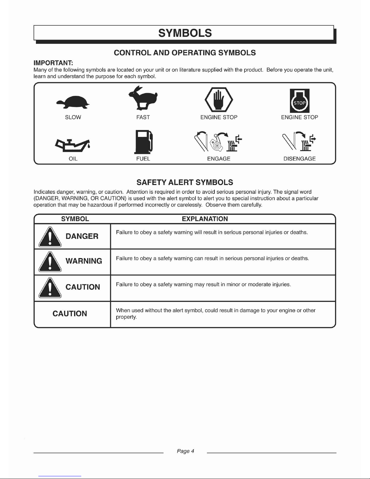
CONTROL AND OPERATING SYMBOLS
IMPORTANT:
Many of the following symbols are located on your unit or on literature supplied with the product. Before you operate the unit,
learn and understand the purpose for each symbol.
~
<I>
FAST ENGINE STOP
j
~
€
Jffi:
~
FUEL ENGAGEOIL DISENGAGE
SLOW ENGINE STOP
SAFETY ALERT SYMBOLS
Indicates danger, warning, or caution. Attention is required in order to avoid serious personal injury.The signal word
(DANGER, WARNING, OR CAUTION) is used with the alert symbol to alert you to special instruction about a particular
operation that may be hazardous if performed incorrectly or carelessly. Observe them carefully.
SYMBOL EXPLANATION
A
DANGER
Failure to obey a safety warning will result in serious personal injuries or deaths.
A
WARNING
Failure toobey a safetywa
rni
ngcan
result
in seriouspersonal inj
uries
or deaths.
A CAUTION
Failure to obey a safety warning may result in minor or moderate injuries.
CAUTION
When used without the alert symbol, could result in damage to your engine or other
property.
Page 4
Page 7
SYMBOLS
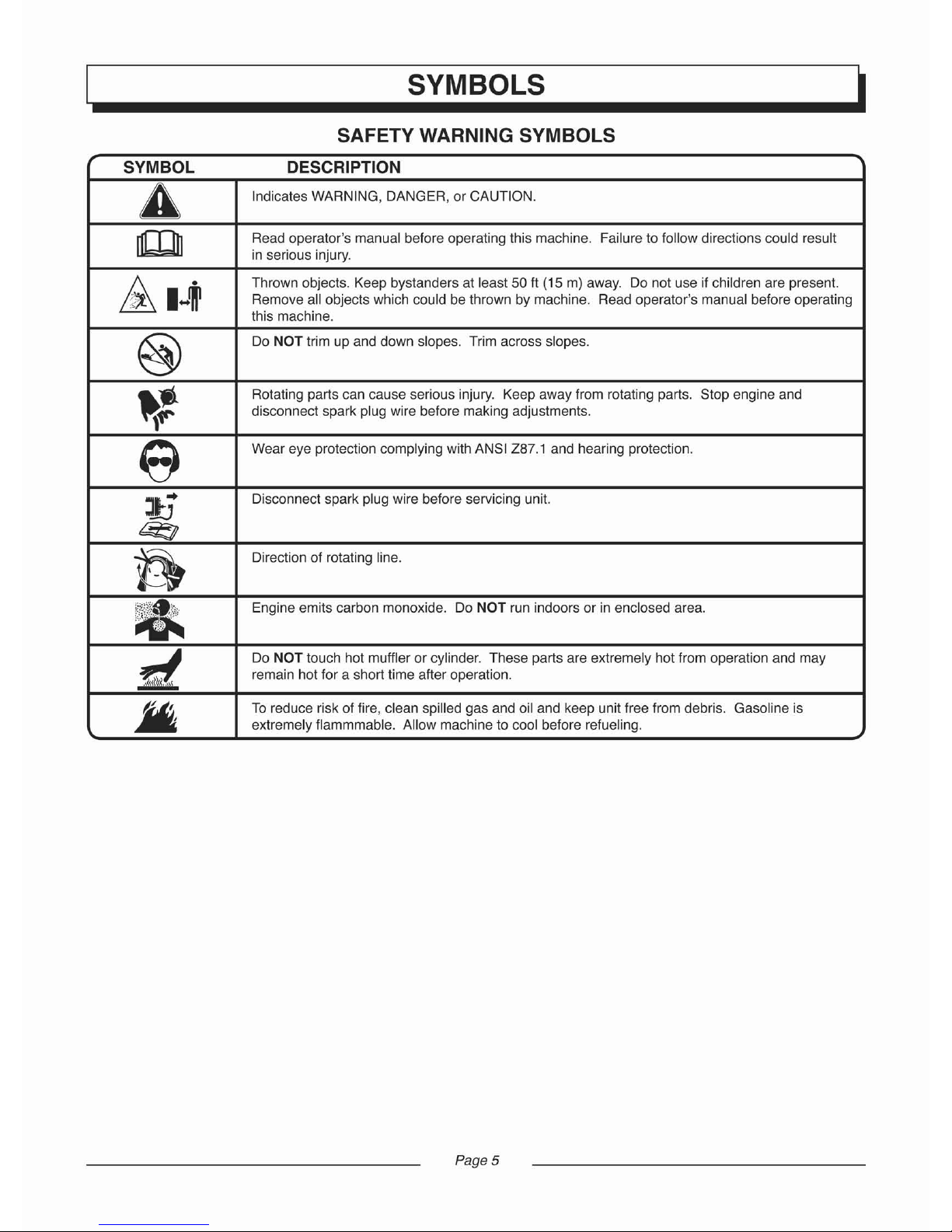
SAFETY WARNING SYMBOLS
SYMBOL DESCRIPTION
A
Indicates WARNING, DANGER, or CAUTION.
m
Read operator's manual before operating this machine.
Failure to follow directions could result
in serious
inj
ury.
~
I -
~
Thrown objects. Keep bystanders at least 50 ft (15 m) away. Do not use if children are present.
Remove all objects which could be thrown by machine. Read operator's manual before operating
this machine.
@
Do NOT trim up and down slopes. Trim across slopes.
~t
Rotating parts can cause serious injury. Keep away from rotating parts. Stop engine and
disconnect spark plug wire before making adjustments.
e
Wear eye protection complying with ANSI 287.1 and hearing protection.
:J6
Disconnect spark plug wire before servicing unit.
~
fi
Direction of rotating line.
*
Engine emits carbon monoxide. Do NOT run indoors or in enclosed area.
d
Do NOT touch hot muffler or cylinder. These parts are extremely hot from operation and may
remain hot for a short time after operation.
.M
To reduce risk of fire,clean spilled gas and oil and keep unit free from debris. Gasoline is
extremely flammmable. Allow machine to cool before refueling.
Page S
Page 8
FEATURES
Engine Displaceme
nt.
160cc Oil Capacity 16.9 oz. [500 ml]
Gasoline Capacity 0.95 qt. [0.9 L] Spark Plug Model. F6RTC
Gasoline Type Unleaded Regular Spark Plug Gap 0.027-0.031 in. [0.7-0.8 mm]
Oil Type (API SG-SL) SAE 30 (above 32 degrees)1 Trimmer Line Length 21.5 in. [546 mm]
...
...
..............
. . . SAE 5W-30 (below 32 degrees) Trimmer Line 0.155 in. [4 mm]
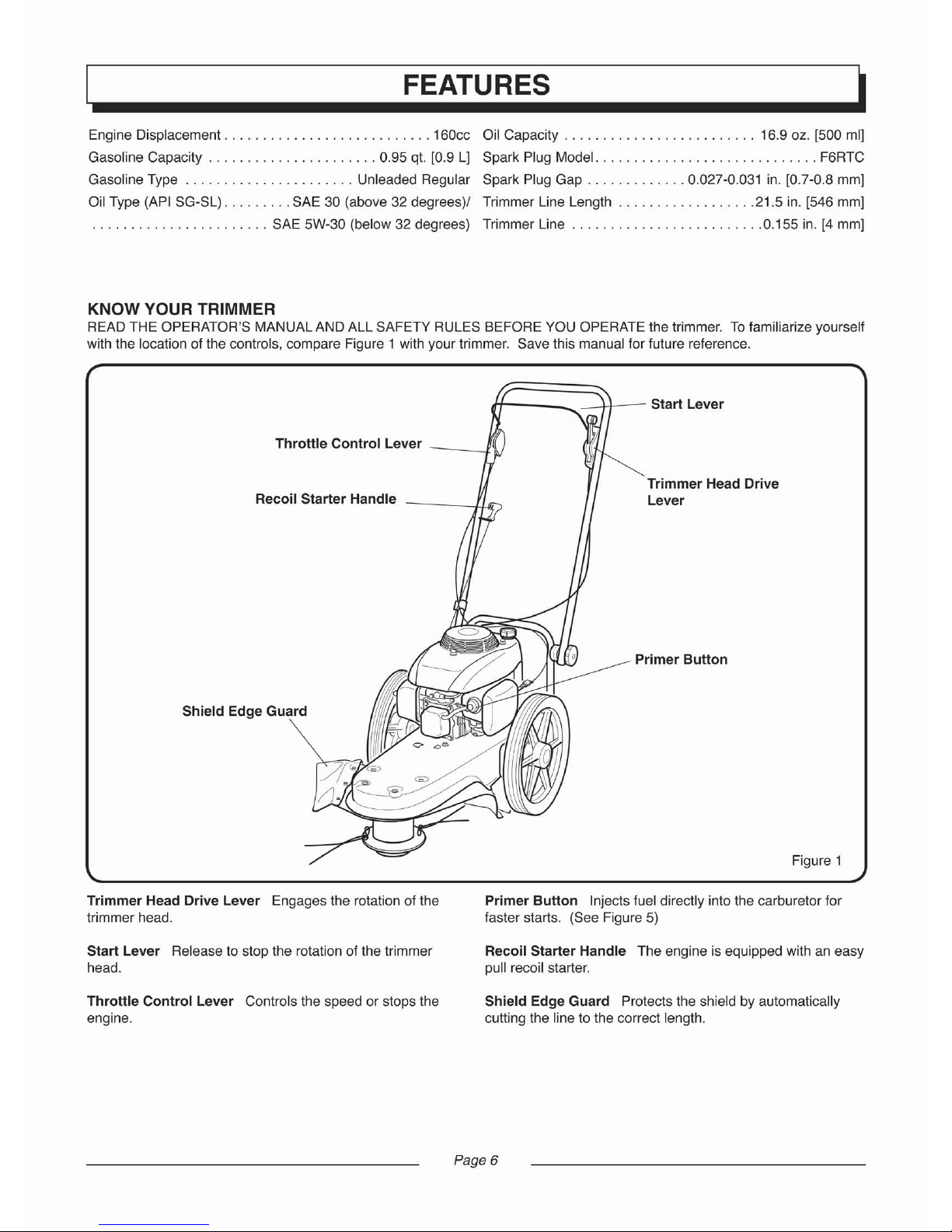
KNOW YOUR TRIMMER
READ THE OPERATOR'S MANUALAND ALL SAFETY RULES BEFORE YOU OPERATE the trimmer. To familiarize yourself
with the location of the controls, compare Figure 1 with your trimmer. Save this manual for future reference.
dt---_..
-
+t---
Start Lever
Throttle Control Lever
---
.n
Recoil Starter Handle
r
I
Trimmer Head Drive
Lever
Shield Edge Guard
Primer
Button
Figure 1
Trimmer Head Drive Lever Engages the rotation of the
trimmer head.
Start Leve r Release to stop the rotation of the trimmer
head.
Throttle
Control
Lever Controls the speed or stops the
engine.
Primer
Button
Injects fuel directly into the carburetor for
faster starts. (See Figure 5)
Recoil Starter Handle The engine is equipped with an easy
pull recoil starter.
Shield E
dge
Guard Protects the shield by automatically
cutting the line to the correct length.
Page 6
Page 9
ASSEMBLY
Read and follow the assembly and adjustment instructions.
Do not discard any parts or materials until the unit is assembled.
NOTE: Torque is measured in foot-pounds (metric unit is
Nm). This measurement describes how tight a nut or bolt
must be. The torque is measured with a torque wrench.
A WARNING
Always wear ANSI compliant safety glasses or eye
shields while assembling the trimmer.
The following components will be found in parts bag with
quantities in ( ):
(1)Field Trimmer Operator's Manual
(1)Engine Operator's Manual
(1)500 ml Bottie of Oil
(1)T-Handle Wrench
(4)0.155 in. Trimmer Lines (4 lines make 2 sets)
TOOLS REQUIRED
(1)Utility Knife to Cut Carton
(1)Oil Funnel
(1)Torque Wrench to Check Fastener Tightness
(1)T-Handle Wrench (included in parts bag)
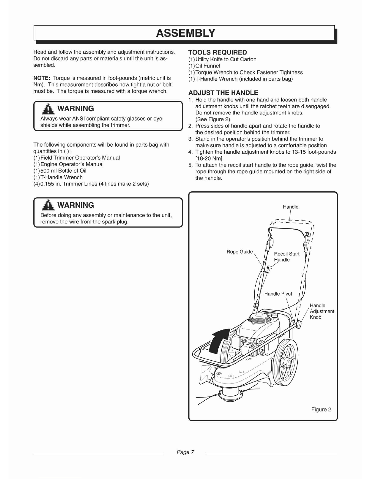
ADJUST THE HANDLE
1. Hold the handle with one hand and loosen both handle
adjustment knobs until the ratchet teeth are disengaged.
Do not remove the handle adjustment knobs.
(See Figure 2)
2. Press sides of handle apart and rotate the handle to
the desired position behind the trimmer.
3. Stand in the operator's position behind the trimmer to
make sure handle is adjusted to a comfortable position
4. Tighten the handle adjustment knobs to 13-15 foot-pounds
[18-20 Nm].
5. To attach the recoil start handle to the rope guide,twist the
rope through the rope guide mounted on the right side of
the handle.
A WARNING
Before doing any assembly or maintenance to the unit,
remove the wire from the spark plug.
Page 7
Rope Guide
Handle
--1
__
II'" - - -
-_
......
1\
I
!II
I,I
Recoil Start I
Handle ,
, I
I
I
,'
HandlePivot
II
Handle
Adjustme
nt
Knob
Figure 2
Page 10
OPERATION
Figure 3
rf1~o
Fuel Tank Cap
Upper Limit
~
/
LowerLimit
-------../'
As you learn how to use the trimmer, pay extra attention to
the following important items:
Engine oil is at proper level.
Fuel tank is filled with a fresh, clean, regular unleaded
gasoline.
Become familiar and understand the function of all
controls. Before you start the engine, operate all controls.
CHECKLIST
For the best performance and satisfaction from this quality product, please review the following checklist before you
operate the trimmer:
All assembly instructions have been completed.
Check carton to make sure no parts are remaining.
All fasteners have been properly tightened.
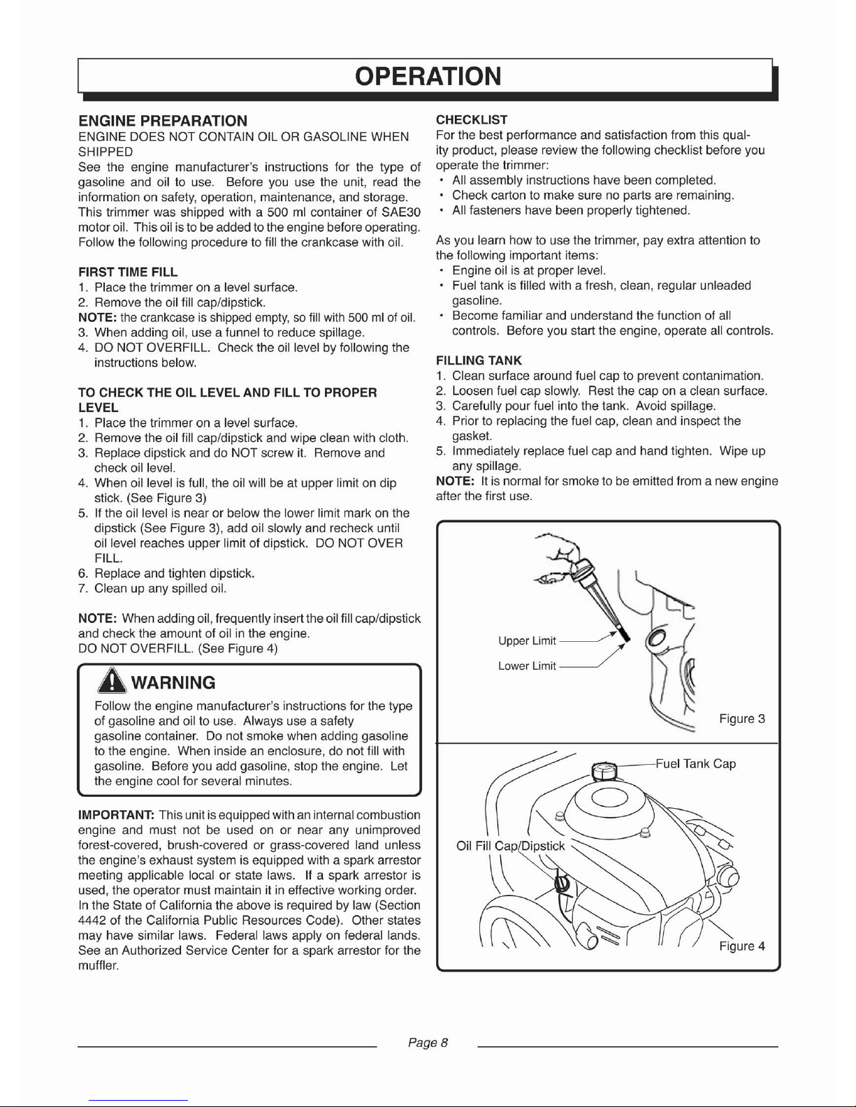
FILLING TANK
1. Clean surface around fuel cap to prevent contanimation.
2. Loosen fuel cap slowly. Rest the cap on a clean surface.
3. Carefully pour fuel into the tank. Avoid spillage.
4. Prior to replacing the fuel cap, clean and inspect the
gasket.
5. Immediately replace fuel cap and hand tighten. Wipe up
any spillage.
NOTE: It is normal for smoke to be emitted from a new engine
after the first use.
NOTE: Whenadding oil,frequently insert theoilfill cap/dipstick
and check the amount of oil in the engine.
DO NOT OVERFILL. (See Figure 4)
A,
WARNING
Follow the engine manufacturer's instructions for the type
of gasoline and oil to use. Always use a safety
gasoline container. Do not smoke when adding gasoline
to the engine. When inside an enclosure, do not fill with
gasoline. Before you add gasoline, stop the engine. Let
the engine cool for several minutes.
IMPORTANT: This unitisequipped with an internalcombustion
engine and must not be used on or near any unimproved
forest-covered, brush-covered or grass-covered land unless
the engine's exhaust system is equipped with a spark arrestor
meeting applicable local or state laws. If a spark arrestor is
used, the
operator
must maintain itine
ffective
working
order.
In the State of California the above is required by law (Section
4442 of the California Public Resources Code). Other states
may have similar laws. Federal laws apply on federal lands.
See an Authorized Service Center for a spark arrestor for the
muffler.
TO CHECK THE OIL LEVEL AND FILL TO PROPER
LEVEL
1. Place the trimmer on a level surface.
2. Remove the oil fill cap/dipstick and wipe clean with cloth.
3. Replace dipstick and do NOT screw it. Remove and
check oil level.
4. When oil level is full, the oil will be at upper limit on dip
stick. (See Figure 3)
5. If the oil level is nearor below the lower limit mark on the
dipstick (See Figure 3), add oil slowly and recheck until
oil level reaches upper limit of dipstick. DO NOT OVER
FILL.
6. Replace and tighten dipstick.
7. Clean up any spilled oil.
FIRST TIME FILL
1. Place the trimmer on a level surface.
2. Remove the oil fill cap/dipstick.
NOTE: the crankcase is shipped empty, sofillwith 500ml of oil.
3. When adding oil, use a funnel to reduce spillage.
4. DO NOT OVERFILL. Check the oil level by following the
instructions below.
ENGINE PREPARATION
ENGINE DOES NOT CONTAIN OIL OR GASOLINEWHEN
SHIPPED
See the engine manufacturer's instructions for the type of
gasoline and oil to use. Before you use the unit, read the
infor
matio
n on safety, operation, maintenance, and
storage.
This trimmer was shipped with a 500 ml container of SAE30
motor oil. Thisoil isto beadded to theengine before operating.
Follow the following procedure to fill the crankcase with oil.
Page 8
Page 11

OPERATION
Figure 5
Figure
7
Figure 6
Figure 8
~Q~I
t--Jrt
;Lf
t
-pr
ime
r
Button
Recoil
Starte
r
Handle
A WARNING
Debris thrown from the trimmer can result in foreign
ob
jec
ts being thrown into eyes , which can cause seve re
eye damage. Always wear ANSI compliant safety
glasses or eye shields when operating the trimm er. If you
wear eyeglasses, put an ANSI certified Wide Vision
Safety
Mask
over your eyeg lasses.
A CAUTION
Never leave the trimmer unattended while the engi ne is
running. Wait for the trimmer lines to stop rotation.
HOW TO USE THE PRIMER BUTTON
NOTE:
Do not use the primer button to restart a warm en-
gine after a short shutdown.
When starting a cold engine, push the primer button three
times (See Figure
5). Wait approx imately two seco nds
between eac h push.
HOW TO START THE ENGINE
NOTE:
DO
NOT
BE ALARMED; your engine will smoke the
first time it is started. It is burning off the protective coati ng
that is on the internal engine parts.
NOTE
: Make sure engine is level before starting.
1. Before each use, remove the debris from the
debr
is
screen. Debris can cause the engine to
over
heat. Wipe the
debris scree n with a cloth or paper towe l.
2. Move the throttle control lever forward to the START or
FAST position.
3. Make sure the fuel line valve is turned on (the knob should
be horizontal). (See Figure 7)
4. To start a cold engine, push the primer button three times.
Wait two seconds between each push of the primer button.
5. Firmly hold the recoil starter handle with your right hand.
(See Figure
8)
6. Pull the recoil starter slowly, until you feel tension in the
starter rope. Th en quickly pull the recoil starter handle
to completely unwind the starter rope. DO NOT allow the
starter rope to snap back. Let the starter rope slowly
rewind as you hold the recoil starter handle.
7. If engine fails to start after three pulls, push the primer
button two times and again pull the recoil starter handle.
8. If engine fails to start after 5 or 6 more tries, see the
instruction in the "Troubleshooting Chart".
HOW TO USE THE THROTTLE CONTROL
1. During normal use, set the throttle control lever in the
FAST position to run the engine at full speed.
2. Pull the throttle control lever back to decrease engine
speed. Push the throttle control lever forward to increase
engine speed .
3. To stop engine, pull the throttle control lever completely
back to the STOP position. (See Figure 6)
Page 9
Page 12
OPERATION
A WARNING
Never run the engine indoors or in a poorly ventilated
area. Engine exhaust contains carbon monoxide, an
odorless and deadly gas. Keep hands, feet, hair and
loose clothing away from the trimmer and any moving
parts on the engine. Avoid the muffler and surrounding
areas. Temperatures may exceed 150 degrees.
HOW TO STOP THE ENGINE
Move the throttle control lever completely back to the STOP
position.
A CAUTION
The trimmer head will continue to rotate for several
seconds after the engine has stopped.
Handle
TrimmerHead
D
rive
Lever
Figure 9
HOW TO STOP THE TRIMMER HEAD
Release the start lever. It will return to its position and
disengage the trimmer head.
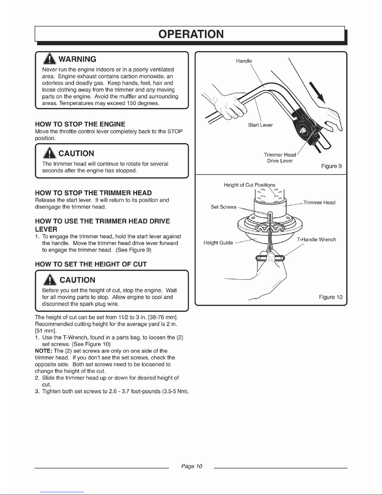
HOW TO USE THE TRIMMER HEAD DRIVE
LEVER
1. To engage the trimmer head, hold the start lever against
the handle. Move the trimmer head drive lever forward
to engage the trimmer head. (See Figure
9)
HOW TO SET THE HEIGHT OF CUT
A CAUTION
Before you set the height of cut, stop the engine. Wait
for all moving parts to stop. Allow engine to cool and
disconnect the spark plug wire.
The height of cut can be set from
11
12to 3 in. [38-76 mm].
Recommended cutting height for the average yard is
2 in.
[51 mm].
1. Use the T-Wrench, found in a parts bag, to loosen the (2)
set screws. (See Figure 10)
NOTE: The (2) set screws are only on one side of the
trimmer head. If you don't see the set screws, check the
opposite side. Both set screws need to be loosened to
change the height of the cut.
2. Slide the trimmer head up or down for desired height of
cut.
3. Tighten both set screws to 2.6 - 3.7 foot-pounds (3.5-5 Nm).
Page 10
Height of Cut Positions
~\:
~
p
~
~
p
~
=
Set Screws
Height Guide
T-Handle W
rench
Figure 10
Page 13
OPERATION
TRIMMING TIPS
A WARNING
Debris such as sticks,gravel, and rocks can be thrown
with sufficient force to cause personal injury or property
damage.
Set the throttle control in the FAST position. The faster the
engine runs, the faster the trimmer head will rotate. If the
weeds or grass are tall and thick, operate the trimmer at a
slower walking speed.
Frequently clean the trimmer to remove any grass build
up. See the Maintenance section for details.
For best results and longer lasting line, use the ends of the
line to do the cutting. This is easily done by moving
slowly through very thick or heavy weeds.
If the trimmer lines become too short, it will take longer to
complete this job.
If the trimmer lines are worn to less
than half their original length, change to a new trimmer
line. See "How to Replace the Trimmer Line" in the
Maintenance section.
Do not trim on excessively steep slopes. See Slope
Guide. If a slope is difficult to stand on, do not trim it.
Do not trim on slopes when the ground is slippery or wet.
Trim across the face of a slope, not up and down.
Trimmer head contact to concrete, asphalt and harder
surfaces may create premature wear to the height guide.
Page 11
Page 14
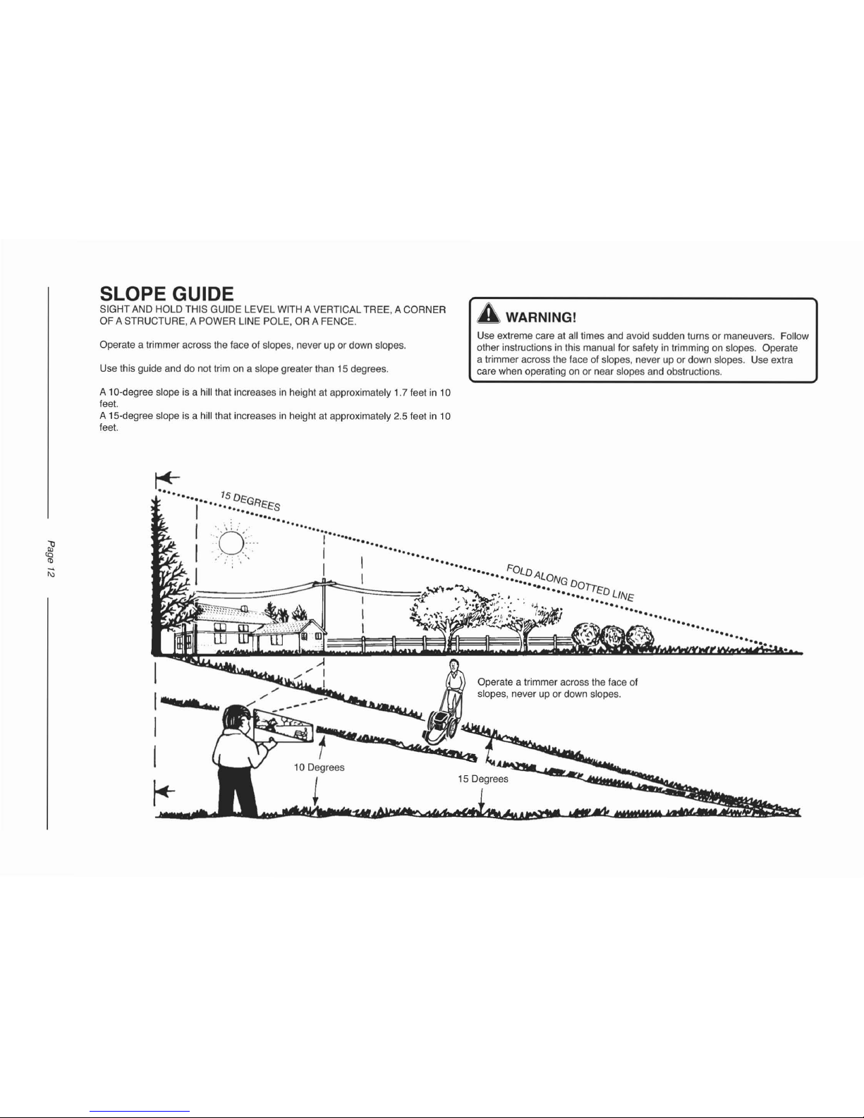
SLOPE GUIDE
SIGHT AND HOLD THIS GUIDE LEVEL WITH A VERTICAL TREE, A CORNER
OF A STRUCTURE, A POWER LINE POLE, OR A FENCE.
A WARNING!
Operate a trimmer across the face of slopes, never up or down slopes.
Use this guide and do not trim on a slope greater than 15 degrees.
Use extreme care at all times and avoid sudden turns or maneuvers. Follow
other instructions in this manual for safety in trimming on slopes. Operate
a trimmer across the face of slopes, never up or down slopes . Use extra
care when operating on or near slopes and obstructions.
A 10-degree slope is a hill that increases in height at app roximately 1.7 feet in 10
feet.
A 15-degree slope is a hill that increases in height at approximately 2.5 feet in 10
feet.
---
Operate a trimmer across the face of
slopes, never up or down slopes.
15 Degrees
.A
-- I
,/
I
r--.ov~
1'=QlIIII:"
~
.,
$
i
'»",,~
1-·
-_
I
I
~
l
i\)
Page 15
MAINTENANCE
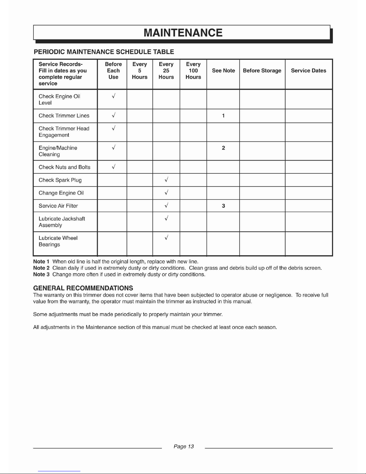
PERIODIC MAINTENANCE SCHEDULE TABLE
Service
Records
-
Before Every Every Every
Fill in dates as
you
Each
5
25
100
See Note
Befo
re Storage Service Dates
complete
regular
Use
Hours
Hours Hours
service
Check Engine Oil
,;
Level
Check Trimmer Lines
,;
1
Check Trimmer Head
,;
Engagement
Engine/Machine
,;
2
Cleaning
Check Nuts and Bolts
,;
Check Spark Plug
,;
Change Engine Oil
,;
Service Air Filter
,;
3
Lubricate Jackshaft
,;
Assembly
Lubricate Wheel
,;
Bearings
Note 1 When old line is half the original length, replace with new line.
Note 2 Clean daily if used in extremely dusty or dirty conditions. Clean grass and debris build up off of the debris screen.
Note 3 Change more often if used in extremely dusty or dirty conditions.
GENERAL RECOMMENDATIONS
The warranty on this trimmer does not cover items that have been subjected to operator abuse or negligence. To receive full
value fromthe warran
ty,
the operatormust maintainthe trimmer as inst
ructed
inthismanual.
Some adjustments must be made periodically to properly maintain your trimmer.
All adjustments in the Maintenance section of this manual must be checked at least once each season.
Page 13
Page 16
MAINTENANCE
ENGINE MAINTENANCE
Use the following maintenance section to keep your unit in
good operating condition. All the maintenance information for
the engine is in the "Engine Operator's Manual". Before you
start the engine, read this manual.
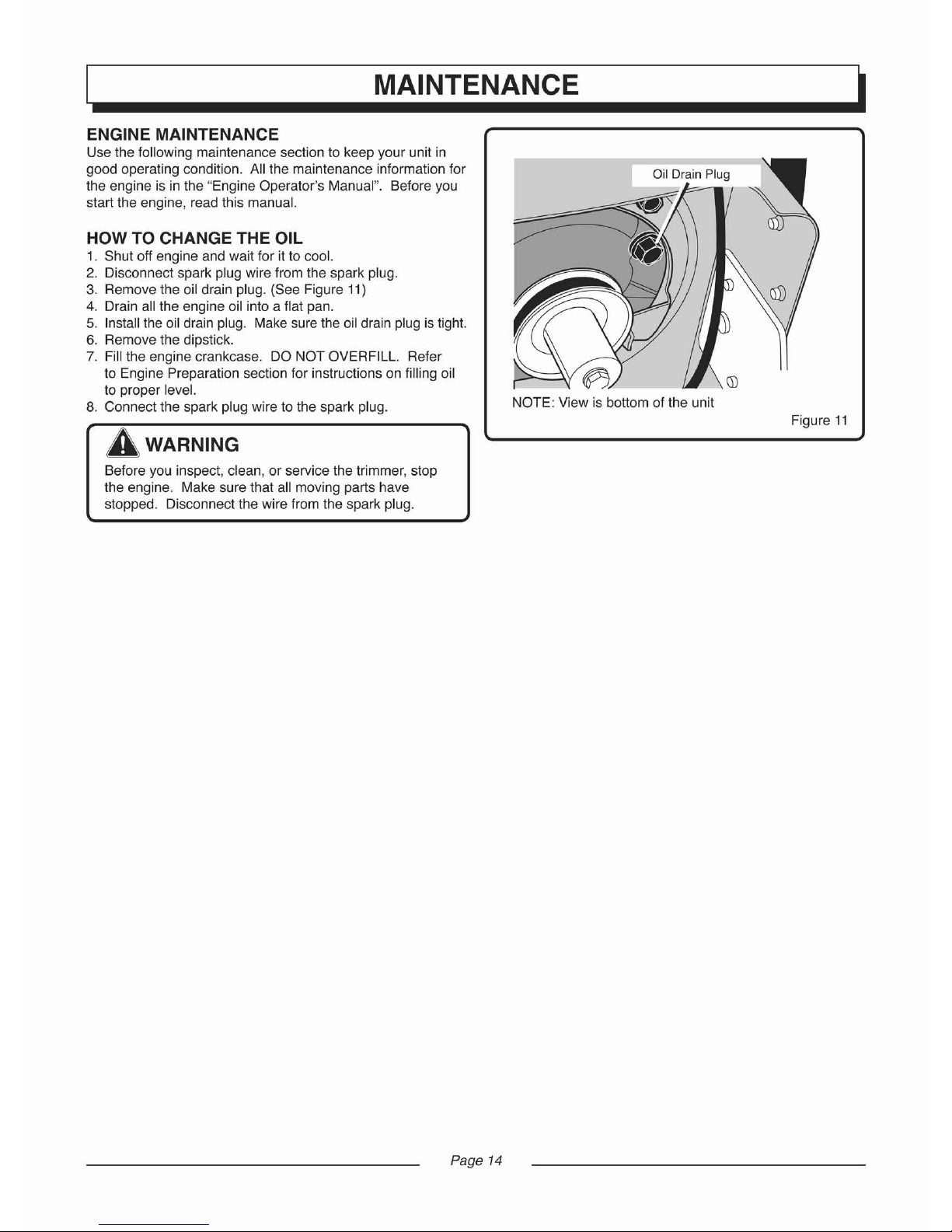
HOW TO CHANGE THE OIL
1. Shut off engine and wait for it to cool.
2. Disconnect spark plug wire from the spark plug.
3. Remove the oil drain plug. (See Figure 11)
4. Drain all the engine oil into a flat pan.
5. Install the oil drain plug. Make sure fhe oil drain plug is tight.
6. Remove the dipstick.
7. Fill the engine crankcase. DO NOT OVERFILL. Refer
to Engine Preparation section for instructions on filling oil
to proper level.
8. Connect the spark plug wire to the spark plug.
A WARNING
Before you inspect, clean, or service the trimmer, stop
the engine. Make sure that all moving parts have
stopped. Disconnect the wire from the spark plug.
Page 14
NOTE: View is bottom of the unit
Figure
11
Page 17

MAINTENANCE
HOW TO REPLACE THE TRIMMER LINE
When the trimmer line becomes worn to half the original
length, replace the trimmer line. For the best performance,
use a heavy gauge 0.155 in. [4 mm] trimmer line.
1. Stop the engine. Wait for all moving parts to stop.
Disconnect the wire from the spark plug.
2. Remove the worn trimmer line from line retainer.
3. Cut the length of the trimmer line to 21.5 in. [546 mm).
Use the length guide; located on the shield to make sure
the trimmer line is the correct length. (See Figure 12)
Do not allow the length of the lines to vary more than one
inch. Make sure the trimmer head is balanced and does
not vibrate.
4. Thread the ends of the new trimmer line through the out
side loops. (See Figure 13)
5. Take the ends of the line,cross over the line retainer, and
thread the ends through the center hole. (See Figure 14)
6. Then, check to make sure that the ends of the line are
even. (See Figure 15)
7. Follow same steps for line on alternate side.
IMPORTANT: To extend the life of the trimmer line, keep the
trimmer line moist.
If not kept moist, the nylon trimmer line
will become dry and brittle. Keep extra trimmer line in a can
of water. The line will then stay flexible and easy to change.
A flexible line will also last much longer.
Figure 12
Page 15
Figure 13
Figure 14
Figure 15
Page 18

MAINTENANCE
Figure 16
Mounting Bolt
1111111
Trimmer Hou
sin
g
Trimmer Head
A WARNING
Before you remove the drive belt, disconnect the wire from
the spark plug.
IMPORTANT: Test the drive system. Start the engine and
move the throttle control to the FAST position. Engage and
disengage the trimmer head several times. When disengaged, make sure the trimmer head completely stops when
resting on the ground. If the trimmer head continues to
rotate, take the trimmer to an authorized Service Center.
NOTE: Make sure you replace the drive belt only with a
replacement belt from the factory. The length of the belt is
45.67±0.1 in. [1160±2.5mm], the angle is
37", and the section
is 3L.
5. To assemble the drive belt, reverse the above steps.
6. The torque specs are 9.6-14.8 foot-pounds [13-20 Nm] for
the shield fasteners, 27-33 foot-pounds [36.6-44.7 Nml for
the drive pulley mounting bolt, and 18-25 foot-pounds
[24.4-34 Nm] for the trimmer head bolts.
7. Check the routing of the drive belt. Make sure the drive
belt is inside of all belt guides and that the belt is not
twisted. (See Figure 17)
To replace the drive belt, the trimmer head and shield must
be removed as follows.
1. Remove the two fasteners that hold the rear of the shield
to the trimmer housing. (See Figure 16)
2. Remove the four fasteners that hold the front of the shield
and trimmer head to the trimmer housing.
3. Remove the "V" Pulley from the idler bracket.
(See Figure 17)
4. Raise the front of the trimmer housing and remove the
drive belt. Do not bend the belt guides.
HOW TO REPLACE THE DRIVE BELT
Drive Pulley
NOTE: View is bottom of the unit
Figure 17
Page 16
Page 19

MAINTENANCE
STORAGE
A WARNING
Never store the trimmer indoors with fuel in the fuel tank.
Never store in an enclosed, poorly ventilated area where
fumes could reach an open flame, a spark or a pilot light
as on a furnace, water heater or clothes dryer. Allow
engine to cool before storing unit.
A WARNING
Do not remove gasoline while inside a building, near a
fire, or whileyousmoke.
Gasoline
fumescancause an
explos
ion ora fire.
NOTE: A yearly checkup or tune-up at an authorized service
center will make sure that the trimmer will provide maximum
performance
for the nextseason.
IMPORTANT: It is important to prevent gum deposits from
forming in fuel system parts such as the carburetor, fuel
filter, fuel hose, and tank during storage. Also, using alcohol-blended fuels (called gasohol, ethanol, or methanol) can
attract moisture, which leads to separation and formation of
acids during storage. Acidic gas can damage the fuel system
of an engine while in storage.
When the trimmer is put in storage for thirty days or more,
follow the steps below to make sure the trimmer is in good
condition the following season.
1. Let the engine run until it is out of gasoline.
2. Change the oil by following instructions under Engine
Maintenance.
3. Remove the spark plug from the cylinder. Pour one
ounce of oil into the cylinder. Slowly pull the recoil-start
handle so that the oil will protect the cylinder. Install a
new spark plug in the cylinder. Pull recoil-start handle
slowly a few times to distribute oil.
4. Clean the dirt and debris from thecylinder cooling fins
and the engine housing.
5. Completely clean the trimmer. Remove all dirt, grease,
leaves, etc.
6. Check the trimmer for worn or damaged parts. Have
damaged parts replaced if necessary.
7. Tighten all loose hardware.
8. Apply lubrication as directed in Maintenance section.
9. Put the unit in a building that has good ventilation.
10. Cover the trimmer with a suitable protective cover that
doesnotretainmoisture. Do not use p
lastic
. Plastic can
not breathe which allows condensation to form and will
cause your unit to rust.
11
. If desired, fold the handle down for storage. Refer to
the "Adjust the Handle" directions in the Assembly
section. When folding the handle for storage or
transportation, be sure to fold the handle as shown or you
may damage the control cables.
Page 17
Page 20

(
Problem
TROUBLESHOOTING
Possible Cause Solution
)
Engine does not start
Engine runs poorly
Engine overheats
Engine will not stop
running
Poortrimming
performance
Spark plug wire disconnected
Engine not primed
Defective or incorrectly gapped spark plug
Fuel tank empty or low
Dirty carburetor or fuel line
Carburetor dirty
Engine flooded
Throttle control lever in incorrect position
Stale gasoline
Defective throttle control leveror wire
Dirty air filter
Sad spark plug
Dirty air filter
Carburetor out of adjustment
Stale gasoline
Engine cooling system clogged
Engine cooling system clogged
Carburetor out of adjustment
Oil level is low.
Defective throttle control lever or wire.
Throttle not adjusted properly.
Trimmer line length is too short
Engine not set at FAST speed
Page 18
Connect spark plug.
Prime engine.
Inspect or replace spark plug.
Add fuel.
Clean carburetor or fuel line.
For carburetor cleaning, take the unit to an
Authorized Service Center.
Wait several minutes before starting.
Move throttle lever to FAST or START position.
Drain old gasoline and add fresh gasoline.
Inspect lever
and
wire.
Replaceifdamaged
orde
fective.
Replace air filter.
Replace spark plug.
Replace air filter.
Adjust carburetor. Take the unit to an authorized
Service Center.
Drain old gasoline and add fresh gasoline.
Clean engine screen and cooling fins.
Clean debris system and engine cooling fins.
Adjust carburetor. Take the unit to an authorized
Service Center.
Add oil.
Inspect and replace damaged parts.
Move throttle to the full OFF position.
Correct line length is 21.5 inches. When less
than 1/2 this length, replace the line.
Move engine throttle lever to FAST position.
Page 21

TROUBLESHOOTING
(
Problem Possible Cause Solution
)
T
rimmervibrates
Set screws for trimmer head is loose Tighten set screw with T-handle wrench.
Trimmer line lengths are substantially different Adjust trimmer line to approximately equa lengths.
Loose nuts or bolts Check all bolts and nuts, including engine bolts.
Broken trimmer head Replace broken part.
Trimmer head does not Trimmer line not properly attached Follow instructions on decal or in the Service
retainline section of the owner's manual.
Broken line retainer Replace the trimmer head assembly.
T
rim
mer
lin
e notco
rrec
t size Use a 0.155 in. (4 mm) trimmer line.
Page 19
Page 22

REPLACEMENT PARTS LIST
Engine and Pulley Assembly
Ref No. Service No. Description Qty.
A100535
Engine
2
A100536
Pulley,Engine
3
A100537
Lock Washer, 010
4
A100538 Bolt
5 A100539
Belt, Trimmer
6
A100540
Bolt
6-i
2
3--
~
5
4
----fl
Handle Assembly
Ref No. Service No. Description Qty.
A100541
Upper Handle
1
2
A100542
Lever, Stop
3 A100543 Lower Handle
r<'
~
4 A100544 Pivot, Handle
4
5 A100545
Washer, Spring 2
16
-1
6
A100546
Washer 2
9
7 A100547 Screw 4
8 A100548
Tie, Cable
3
1
4
9
A100549
Guide, Rope
8
(t
10 A100550
Knob, Handle
2
I
~'
11
A100551
Control,Throttle
4
5 \
Va
6
12
A100552
Cable, Control Latching
I
10
13 A100553 Tubing Foam
5
"'3
\
14
A100554
Bolt, M8x85 2
15
A100506
Nut, M6 3
16 A100555 Bolt, M6x50 2
Page 20
Page 23

REPLACEMENT PARTS LIST
Wheel Assembly
Ref No. Service No. Desc
ription
Qly
.
A100556 Spacer 2
2
A100557
Washer, Spring 2
3 A100458
Boll, M8x16 4
~
~
,
4
A100558
Assembly, Axle & Bracket 2
2
5 A100559 Wheel & Tire 2
4
~
6
6 A100560
Bearing 4
Q
7
A100462
Nut, M10 2
7
6
5
Handle Assembly
Ref No. Se
rvice
No.
Descriplion
Qly
.
A100561
Frame,Trimmer 1
2
A100562
Spacer Assembly,
Jackshaft
3
A100563
Screw 4
4
A100564
Bracket, Idler Assembly
5
A100565
Pulley, Idler
6
A100566
"V" Pulley
7
A100567
Shield,Trimmer
8
A100568
Blade
2
9
A100569
Bolt
10
A100570
Spring, Extension
11
A100571
Shied, Trailing
12
A100572
Flap, Debris
13
A100573
Screw 2
14
A100574
Boll, Carriage, M6x283
12
15
A100506
Nut, M6
16
A100462
Nut, M10
3
17
A100575
Screw, ST4.8x12 4
18
A100576
Screw 4
8
Page 2 1
Page 24

REPLACEMENT PARTS LIST
I
Trimmer Head Assembly
Ref No. Service No.
Description
Qty.
17~
r
tr
1
Nut, M1Ox1.25 1
..i..-
2
A100462
16
-:-{j
\
2
A100577
Washer, Flat ,,10
\
3
A100578
Pulley, Cutting Head
\;~4
4
A100579
Spacer
5
A100580
Wrap Weed, Upper BLK
15
/
Screw
3
~
6
A100581
7
A100582
Shaft, Cutting Head
14
8
A100583
Wrap Weed, Lower BLK
5
9
A100584
Screw
2
10
A100585
Wrench, T-Handle
1
11
A100586
Assembly, Cutter Head
& Wrap
7
12 A100587 Guide Assembly, Height
13 A100588
Lin
e, Trimmer 2
14 A100589 Bearing, 6203
15 A100590 Housing, Jackshaft
9
16 A100591 Spacer
./
10 17 A100592 Bearing, 99502
~
'\
13
Page
22
Page 25

LIMITED WARRANTY
'-
.....
1
HOMELITE CONSUMER PRODUCTS (HCP)
LIMITED WARRANTIES
Products
Purchased for
Consumer
Use: This limited
warrantyapplies only to Homelile-brand productspurchased
for consumer use (consumer use means personal, family
or household use). This limited warranty does not apply
to products purchased for commercial, rental, industrial or
other non-consumer uses, but the "Warranty on Products
Purchased for Non-Consumer Use" set forth below applies
to such products.
Limited
Warranty:
Homelile
Consumer
Products
, Inc.
("HCP")warrantsto the originalconsumerpurchaserthatthis
Homelite-brandproduct will be free from defects in material
andworkmanshipduringtheone-yearperiodbeginningonthe
date of retail purchase by the original consumer purchaser.
HCP's entire liability and your exclusive remedy under this
limited warranty in the event of a breach will be for HCP
to either repair or replace (at HCP's option and expense)
the defective product. HCP does not assume, or authorize
anyone to assume for it, any other obligation. HCP's limited
warranty is subject to the exclusions and limitations set forth
below.
How to Obtain W
arranty
Service: To make a claim under
this limited warranty, you must return the product, including
any defective part, to an HCP
Autho
rized Service Center
within the warranty period. You must include with the return
a sales receipt or other reasonable proof showing the date
of retail purchase in order to establishthatthe return is being
made withinthe warranty period.To locateyournearest HCP
Author
ized Service Center, please call us at 1-800-242-
4672, or log on to our website at www.home
lile.co
m.
HCP will process your return, and if the product is defective,
will repair or replace (at HCP's option and expense) the
product. You must pay the expenseof deliveringthe product
to the Authorized Service Center for warranty work, and
the expense of having the product returned to you after
repair or replacement.
Implied
Warranties: IN NO EVENT SHALLANY IMPLIED
WARRANTIES, INCLUDING BUT NOT LIMITED TO ANY
WARRANTIES OF MERCHANTABILITY OR FITNESS
FOR PARTICULAR PURPOSE, EXTEND BEYOND THE
WARRANTY PERIOD OF THE LIMITED WARRANTY
IDENTIFIEDABOVE,OR INTHE CASEOFCOMPONENTS
COVERED BY THE EMISSION CONTROL SYSTEM
WARRANTY SET FORTH BELOW, THE WARRANTY
PERIOD OF THAT WARRANTY.
Some states do not allow limitations on how long an implied
warranty lasts, so the above limitation may not apply to you.
This warranty gives you specific legal rights, and you may
also have other rights which vary from state to state.
Exclusions
: This limited warranty shall not apply to any
product that has been subjected to misuse, abuse, neglect,
negligence or accident, or that has been operated in any
way contrary to the operating functions as specified in the
Operator's Manual. This limited warranty shall not apply to
any damage to or defects in any product that result from
improper maintenance or storage,or to any product that has
been altered or modifiedwithout HCP'swritten consent. This
limited warranty does not extend to repairs made necessary
by normal wear, or by the use of parts or accessories which
are either incompatible with the Homelite-brand product or
adversely affect lts operation, performance or durability.
In addition, this limited warranty does not cover:
A. Wear Items, such as Bump Knobs, Outer Spools,
Cutting Lines, Inner Reels, Starter Pulleys, Starter
Ropes, Drive Belts, Tines, Felt Washers, Hitch Pins,
Blades of any kind, Blower and Vacuum Tubes, Vacuum
Bags and Straps, Guide Bars, Saw Chains, Wheels and
Soft Grips;or
B. Tune-ups of Spark Plugs, Carburetor, Carburetor
Adjustments, Ignition or Filters.
Lim
itat
ionofLiability
: INNO EVENTWILLHCPBELIABLE
FOR ANY CONSEQUENTIAL OR INCIDENTAL DAMAGES
ARiSING FROM OR OUT OF THE PURCHASE OR USE
OF ANY HOMELITE-BRAND PRODUCT, INCLUDING,
BUT NOT LIMITED TO, EXPENSE OF RETURNING THE
PRODUCT TOAN HCP AUTHORIZED SERVICE CENTER
AND EXPENSE OF HAVING IT DELIVERED BACK TO
THE OWNER, TELEPHONE OR FACSIMILE CHARGES,
RENTAL OF A LIKE PRODUCT WHILE WARRANTY
SERVICE IS BEINGPERFORMED, LOSS OF OR DAMAGE
TO PERSONAL
PR
OPERT
~
LOSS OF REVENUE OR
PROFIT, LOSS OF USE OF THE PRODUCT, LOSS OF
TIME, OR INCONVENIENCE. IN NO EVENT WILL HCP'S
LIABILITY FOR ANY CLAIM, WHETHER IN CONTRACT,
WARRANTY, TORT (INCLUDING NEGLIGENCE AND
STRICT LIABILITY) OR UNDER ANY OTHER THEORY
OF LIABILITY, EXCEED THEAMOUNT PAID BY YOU FOR
THE PRODUCT.
Some states do not allow the exclusion or limitation of
incidentalor consequential damages,so the above limitation
or exclusion may not apply to you.
Ex
clusivity;Emission
Control
System
Warranty:
The limited warranty set forth above, and the Emission
Control System Warranty included with this product, are
exclusive and in lieu of all other express warranties on
Homelite-brand products purchased for consumer use.
Page
23
Page 26

LIMITED WARRANTY
HOMELITE CONSUMER PRODUCTS (HCP)
LIMITED WARRANTIES
-- WARRANTY ON PRODUCTS PURCHASED
FOR NON-CONSUMER USE
ProductsPurchased
for Non-Consumer Use:
This warranty applies only to Homelite-brand products
purchased for commercial, rental, industrial or other nonconsumer uses. This warranty does not apply to products
purchasedforconsumer use (consumerusemeanspersonal,
family orhousehold use),but the "Limited Warranty" set forth
above applies to such products.
Warranty: Hometite Consu
mer
Products, Inc. ("HCP")
warrants to the original retail purchaser that this Homelite brand product will be free from defects in material and
workmanship during a period of 90 calendar days beginning
on the date of purchase by the original retail purchaser.
HCP's entire liability and your exclusive remedy under this
warranty in the event of a breach will be for HCP to either
repair or replace (at HCP'soptionand expense) thedefective
product. HCP does not assume, or authorize anyone to
assume for it,any other obligation. HCP'swarranty is subject
to the exclusions and limitations set forth below.
HowtoObt
ain Warra
nty
Serv
ice: To make a claim under
this warranty, you must return the product, including any
defective part, to an HCP Authorized Service Centerwithin
the warranty period.You must include with the return a sales
receipt or other reasonable proof showing the date of retail
purchase in order to establish that the return is being made
within the warranty period. To locate your nearest
HCP
Author
ized Service Center, please call us at 1-800-
242-4672, or log on to our website at www.homelite.com.
HCP will process your return, and if the product is defective,
will repair or replace (at HCP's option and expense) the
product. Youmust paytheexpense of delivering the product
to the Authorized Service Center for warranty work, and
the expense of having the product returned to you after
repair or replacement.
No
Implied
Warranties: HCP DISCLAIMS ANY AND ALL
IMPLIED WARRANTIES, INCLUDING BUT NOT LIMITED
TO ANY WARRANTIES OF MERCHANTABILITY OR
FITNESS FOR PARTICULAR PURPOSE, WITH RESPECT
TO PRODUCTS PURCHASED FOR COMMERCIAL,
RENTAL, INDUSTRIAL OR OTHER NON-CONSUMER
USES.
Exclus
ions:
This warrantyshall not applyto any productthat
has been subjected to misuse, abuse, neglect, negligence
or accident,or that has been operated in any way contrary to
theoperating functions as specified in theOperator's Manual.
This warranty shall not apply to any damage to or defects
in any product that result from improper maintenance or
storage, or to any product that has been altered or modified
without HCP'swritten consent.Thiswarrantydoesnotextend
to repairs made necessary by normal wear, or by the use of
parts or accessories which are either incompatible with the
Homelile-brand product or adversely affecf its operation,
performance or durability.
In addition, this warranty does not cover:
A. Wear Items, such as Bump Knobs, Outer Spools,
Cutting Lines, Inner Reels, Starter Pulleys, Starter
Ropes, Drive Belts, Tines, Felt Washers, Hitch Pins,
Blades of any kind, Blower and Vacuum Tubes, Vacuum
Bags and Straps, Guide Bars, Saw Chains, Wheels and
Soft Grips; or
B. Tune-ups of Spark Plugs, Carburetor, Carburetor
Adjustments, Ignition or Filters.
Limitationof
Liab
ility
: INNO EVENT WILLHCP BELIABLE
FOR ANY CONSEQUENTIAL OR INCIDENTAL DAMAGES
ARISING FROM OR OUT OF THE PURCHASE OR USE
OF ANY HOMELITE-BRAND PRODUCT, INCLUDING,
BUT NOT LIMITED TO, EXPENSE OF RETURNING THE
PRODUCT TO AN HCP AUTHORIZED SERVICE CENTER
AND EXPENSE OF HAVING IT DELIVERED BACK TO
THE OWNER, TELEPHONE OR FACSIMILE CHARGES,
RENTAL OF A LIKE PRODUCT WHILE WARRANTY
SERVICE IS BEINGPERFORMED, LOSSOF OR DAMAGE
TO PERSONAL
PR
OPERT
~
LOSS OF REVENUE OR
PROFIT, LOSS OF USE OF THE PRODUCT, LOSS OF
TIME, OR INCONVENIENCE. IN NO EVENT WILL HCP'S
LIABILITY FOR ANY CLAIM, WHETHER IN CONTRACT,
WARRANTY, TORT (INCLUDING NEGLIGENCE AND
STRICT LIABILITY) OR UNDER ANY OTHER THEORY
OF LIABILITY, EXCEEDTHE AMOUNT PAID BY YOU FOR
THE PRODUCT.
E
xclusivi
ty;
Emission
Control
System
Warranty:
The warranty set forth above, and the Emission Control
System Warranty included with this product, are exclusive
and in lieu of all other warrantieson Homelite-brand products
purchased for commercial, rental, industrial or other non-
consumer uses.
CAll
US
FIRST
For any questions about operating or maintaining your product,
call the Homelite® Help Line!
Yourproduct has been fully tested prior to shipment to ensure
your complete satisfaction.
Page 24
Page 27

ite®
MANUAL DEL USUARIO
Segadora de hilo para campo abierto,
de ruedas altas, a 4 ciclos, modele
UT13144
Esta segadora de hilo ha sido disenada y fabricada conforme a nuestro alto estandar de confiabilidad,
facilidad de uso y seguridad del usuario.
A ADVERTENCIA: :Para reducir el riesgo de lesiones, es preciso que el usuario lea y entienda el manual del
__
usuario antesde
utili
zar este
produ
cto.
Gracias por su compra.
GUARDESE ESTE MANUAL PARA REFERENCIA FUTURA
11/0212006
Page 28

TABLA DE MATERIAS
• Reglas generales de seguridad 1-2
• Reglas especificas de seguridad 3
• Simbolos .4-5
• Caracteristicas 6
• Montaje 7
• Funcionamient
o.....
. . . . . .
.........
8-11
• Guia para pendientes 12
• Mantenimiento 13-17
• Diagn6stico
y resoluci6n de problemas 18-19
• Usta de piezas de repuesto 20-22
• Garantia 23-24
• Servicio al cliente 24
INTRODUCCION
'-
.....
1
Esta herramienta posee muchas caracleristicas para hacer su uso mas placentero y agradable. En el disefio de esle pro-
duclo, se ha dado la
mas alta prioridad a la seguridad, rendimienlo y confiabilidad para facilitar el mantenimiento y uso del
mismo.
Page 29

'-
.....
1
IREGLAS GENERALES DE SEGURIDAD
Se ha redactado este
manua
l para una persona con cierta
destreza rnecanica. AI igual que en la mayo ria de manu ales
de mantenimiento, no se han descrito todos los pasos. Los
pasos sobre c6mo aflojar
0 apretar sujetado res son pa-
sos que toda persona con cierta destreza rnecanica puede
seguir. Leer y acatarestas
instruccio
nes antesde u
tilizar
la
unidad.
Conozcase
el producto: Si se entiende la unidad y como
esta funciona, se obtendra el mejor rendimiento. Mientras se
lee este manual, compararlas ilustraciones conla unidad.
Aprenderse la ubicaci6n y las funciones de los controles .
Para ayudara evltar un accldente, seguir lasi
nstruc
ciones
de uso y las reglas de seguridad . Guardar este manual para
rererencia futura.
I
MPORT
ANTE
: Muchas unidades vienen desmontadas y se
las vende en cajas. Es responsabilidad del usuario asegu-
rarse que las instrucciones de montaje en este manual
S8
sigan al pie de la letra. Otras unidades vienen ya montadas
al efectuarse la compra. En las unidades ya montadas, es
responsabilidad del usuario asegurarse que la unidad este
montada correctamente. EI usuario ha de revisarc
uidado
sa-
mente la unidad conforms a las instrucciones en
este manual
antesdel primer usa de la misma.
RESPONSABILIDAD DEL USUARIO
Es responsabilidad del propietario seguir las instrucciones
siguientes:
1. Leer y acatar cuidadosamente las reglas para un uso
seguro.
2.Acatar todas las instrucciones de montaje y preparaci6n.
3. Inspeccionar la segadora peri6d icamente. Verificar que no
haya piezas dobladas,
dafia
das 0f1ojas.
4. Utilizareste equipounicarnente para su usa previsto.
5. Asegurarse que el usuario de la unidad sepa c6mo utilizar
correctamente todo el equipo estandar y losaccesorios.
6. Utilizar la unidad solo con protectores, pantallas y otros
elementos de seguridad instalados y en buenas
condiciones.
7. Ajustar la unidad correctamente.
8. Dar mantenimiento a la unidad solo con piezas de repues
to autorizadas
0 aprobadas.
9. Completar ta totalidad del mantenimiento de la unidad.
A ADVERTENCIA
La presencia de este slmbolo senala precauciones de
seguridad importantes . Significa: "iAtenci6nl
iPonte alertal
Tu seguridad esta de por medio.
AADVERTENCIA
EI gas de escape del motor, algunos de sus constituy-
antesy ciertos componentesde vehfculoscontienen 0
emiten substancias quimicas que, consta al Estado de
California, producencancer y malformaciones co
nqs
ni-
las u otros danos reproduclivos.
Los bornes, terminales y accesorios relacionados del
acumu lador contienen plomo y compuestos con plomo,
substa ncias quimicas que, consta al Estado de Cali-
fornia, producen cancery ma
lformaciones
conqenitas
u otros danos reproductivos. LAV
ARSE
LAS MANOS
DESPUES DE MANIPULARLOS.
A ADVERTENCIA
Para evitar el arranque accidental al montar, transportar,
ajustar 0 efectuar reparaciones, siernpre desconectar el
cable de la bujia y colocarlo donde no pueda entrar en
conlactocon asia.
PRAcTICAS DE
usa
SEGURO ANTES DE LA
UTILIZACION·
Leer, enlender y acatar lodaslas inslrucciones en la
rnaquina y en los manuales. Familiarizarse cornpleta-
mente con los controles y el uso apropiado de la segadora
antes del arranque.
Sepa
se como parar ta segadora y
desengranar los controles rapida rnente .
Familiarizarse con todos los marbetes de seguridad y
funcionamiento de este equipo .
Inspeccionar com pletamente el
area en que se va a
utilizar la segadora y relirar todo obje to extrario. Esta
segadora puede lanzar objetos pequenos a gran
velocidad y causar lesionesperso nales 0 dartos a la
propiedad. Mante nerse alejado de objetos fraqiles , tales
como ventanasde viviendas, para
brisas
de autornovlles,
invernaderos,
Inspeccionar ta palanca y el cable del control de estran
gulaci6n. Verifica r que el cable este libre y que la palanca
no este canada. Tarnbien, verificar que el varillaje que
conecta al carburador no tenga dobleces, dispositivos
f1
ojos ni obstrucciones, Verificar que la barra de control de
arranque/paro
este funcionando apropiadame nte.
Verificar que todas las tuercas y pernos esten apretados y
que el equipo
este en buenas condicion es. Verificar los
herrajes de montaje en el cabezalde la segadora cada
vez que se cambie el hila de la misma, antes de cada uso.
SEGURIDAD DURANTE EL
usa
Jarnas permitir que nifios 0 adolescentes j6venes utilicen
la segadora.
Mantener el
area de trabajo libre de circunstantes, particu
larmenle nines pequerios y mascotas.
Keep bystanders at least 50 It (15 m) away.
Per
miti
r solo a individuos responsables,familiarizados con
las instrucciones, utilizar la segadora.
No utilizar la segadora bajo la influencia de alcohol,
Pagina 1
Page 30

REGLAS GENERALES DE SEGURIDAD
tarrnacos u otro medicamento que pudiera causar som
nolencia
0
alec
tar la capacidad de utilizar la rnaquina de
manera segura.
No utilizar esta rnaquina siS8as mental 0
ffsica
mente
incapaz de
util
izarla de manera
segura.
AI utilizar la segadora, siempre usar
galas
de seguridad
con pantallas laterales, homologadas por ANS I, para
protegerse los ojos contra objetos extranos que pudieran
ser lanzados por la unidad.
Vestir lndumentaria apropiada tal como una camisa 0 cha
queta de manga larga. Tarnbien, vestir pantalones largos.
NO vestir pantalones cortos. NO vestir indumentaria hoi
gada
que pudiera atorarse en este equipo.
Siempre vest ir guantes de trabajo y calzado robusto tal
como zapatos de cuero para trabajo
0 botas cortas. Estes
protegen los tobillos y la tibia cont ra palos pequenos, astil
las y otros despojos lanzados. Asimismo, estes mejoran la
tracci6n.
Es aconsejable vestir indurnentaria para proteger la
cabeza contra golpes de particulas pequenas lanzadas,
0
contra golpes de ramas bajas, rarnitas u otros objetos
que pudieran pasar
desa
percibidos por el usuario.
No coloca r ni las manos ni los pies cerca de piezas rotati
vas
0 debajo de las mismas.
AI cruzar accesos vehiculares 0 peatonales con grava,
o caminos, parar la rotaci6n del cabezal de la segadora y
esperar a que los hilos de la segadora paren. Tener
cuidado extreme. Mantenerse alerta ante peligros ocultos
o transite.
Tener c
uidado
para no deslizarse0 caerse.Jarnas utilizar
la segadora en cesped humedo, Siempre asegurar el
apoyo de los pies; mante
ner
una sujeci6n firme del
as
idero
ycaminar;[arnas correr.
Mirar bacia atras y tener cuidado al retroceder.
Jarnas utilizar la segadora sin buena visibilidad
0 luz.
No poner en marcha el motor en espacios interiores 0
dentro
de un area cerrada.
Los gases del escape son peligrosos,contienen
MONOXIDO DE CARBONO, un GAS INODORO Y
LETAL.
Jarnas dejar ta segadora desatendida rnientras el motor
8sM.
en marcha. Pararel motor y asegurarse quetodas
las piezas m6viles hayan parado. Desconectar el cable
del a bujia.
Si la segadora
come
nzara a vibrar anormalmente, parar el
motor,
desco
nectar el cable de la bujia y evltar que este
haga contacto con la bujia. Tratar de identificar la causa
inmediatamente. Generalmente, la
vibraci6
n indica
problemas
Tener cuidadoconag
ujeros
, zu
rcos
, abultamientosu otro
terreno escabroso. EI pasta alto puede ocultar obstaculos .
No segarexcesivamente laspendientespronunciadas
(15 grados, maximo). Consultar la "Guia para pendientes"
al dorso de este manual para verificar una pendiente.
Siempre segar a traves de la pendiente; [arnas hacia
arriba y hacia abajo. Tener sumo cuidado al cambiar de
direcci6n en pendientes. Si
S8
esta inseguroen una
pendiente, NO segaria .
NO segar cerca de desniveles pronunciados , zan
jas
0
terraplenes. EI usuario podria perder el apoyo 0 equilibrio.
Pagina 2
Page 31

REGLAS ESPECiFICAS DE SEGURIDAD
SEGURIDAD DEL COMBUST IBLE
Manipular el
comb
ustible con cuidado ; este es altamente
inflamable.
Utilizar un contenedor aprobado.
Revisar el suministro de combustible antes de cada uso,
dejar espacio para expans i6n puesto que el calor del
motor y/o el sol puede(n) causar la expansion del
combustib le.
L1
enar el tanque de combustible al aire libre, con sumo
cuidado. Jarnas lIenar el tanque de combustible en
espacios
interio
res
.
Jarnas retirar la tapa del combustible ni abastecer
combustible con el motor en rnarcha, Dejar que el motor
enfrie antes de reabastecerlo de combustible.
No fumar mientras se reabastece combustible.
Despues del reabastecimiento de combustible, colocar
nuevamente la tapa del tanque de combustible de manera
segura y enjugar el combustible derramado.
Jarnas almacenar
comb
ustible 0 la segadora con com
bustible en el tanque dentro de un edificio donde los
vapores podrian Ilegar a una llama abierta.
SEGURIDAD DE ALMACENAMIENTO
Siempre cons ultar las instrucciones del Manual del usuario
para obtener in
formacio
n importante pormenorizada si
se va a guardar la segadora durante un periodo de tiempo
prolongado.
Jarnas
almacenarla segadoracon
combus
tible en el
tanque dentro de un edificio donde haya fuentes de
ignici6n tales
como
calentado res de agua, calentadores
unitarios, secadorasde ropa,etc.
Para reducir el riesgo de incendio, mantener la segadora
libre de cesped, hojas y acumutacion de otros resid uos.
Dejar que el motor se enfrie antes de almacenarlo en
cualquier recinto.
REPARACION, MANTENIMIENTO Y SEGURIDAD DE AJUSTE
Oespues de golpear un objeto extrano, parar el motor.
Desconectar el cable de la bujia y mantenerlo alejado
de esta paraevitar unarranqueaccide
ntal.
Inspeccionar
exhaustivamente ta segadora para determinar si ha sufrido
dartos. Si esta danada, efectuar las gestiones para que un
tecnico capacitado la repare antes de arrancarla y utilizarla
nuevamente.
Parar el motor antes de limpiar, reparar 0 inspeccionar ta
unidad. Verificar que todas las piezas m6viles hayan
parado. Dejar que el motor se enfrie. Desconectar el cable
de la bujia y alejarlo de esta,
Jamas intentar a
jus
te alguno mientras el motor este en
marcha, exceptocuandoasl10recomiende el fabricante
espec ificamente.
Mantener la segadoraen condicionesde funcionamiento
segura. Revisar todoslos sujetadoresa
intervalos
frecuentes para una sujeci6n apropiada.
AI dar mantenimiento a la segadora 0 repararla, no inelinar
la rnaquin a lateral0 lo
ngitu
dinalmente a rnenos que asi
10
instruya este Manual especificamente. Los procedimientos
de mantenimiento y reparac ionS8pueden efectuarcon
la segadora en la posici6n vertical. Algunos
procedimientos seran
mas taclles si se coloca la rnaquina
sobre una plataforma
0 superficie de trabajo elevada.
Utilizar solo equipo original 0 piezas de repuesto
autorizadas.
Jamas manipular imprudentemente los dispositivos de
seguridad. Verificar el funcionamiento apropiado de los
rnis
mos periodicarnente.
No cambiar la configuraci6n del regulador del motor ni
sobreacelerar el motor.
Limpiar y reemplazar los marbetes de seguridad e
instrucciones sequnsea necesario..
Para prevenir el sobrecalentamiento del motor, siempre
tener el filtro de impurezas limpio e instalado en el motor
instalado.
SEGURIDAD DE NINOS
Accid
entes traqicos pueden ocurrir sielusuariono esta
alertaa la presencia de nines. A menudo, los nines se ven
atraldos por la segadora y el segado mismo.
Mantener a los nines fuera del
area de segado y bajo la
supervisi6n de un adulto respo nsable.
Jarnas
suponer
que los nines perrnaneceran dondese los
vio la ultima vez.
Estar alerta y apagar la segadora si alqun nino entra en el
area.
Antesde retrocedery mientras se retrocede, ver hacia
atras y hacia abajo para asegurarse que no haya nines.
Jarnas permitir que nines utilicen la segadora .
Tener
sumo
cuidado al utilizar la segadora cerca de
esquinas sin visibilidad
e1ara,
arbustos, arboles u otros
objetos que pudieran obstru ir la visio n.
Pagina 3
Page 32

SIMBOLOS
SfMBOLOS DE CONTROL Y FUNCIONAMIENTO
IMPORTANTE:
Muchos de los sirnbolos siguie ntes estan ubicados en la unidad 0 en ta documentaci6n provista con el producto. Antes de
utilizar la unidad, aprender y entender el prop6sito de cada simbolo .
MARCHA LENTA
ACEITE
?
<I>
rI
MARCHA R
AplD
A
PARAR MOTOR PARAR MOTOR
il
~
€
J}
~
~
1
~
COMBUSTIBLE
ENGRANAR DESENGRANAR
SfMBOLOS DE ALERTA PARA SEGURIDAD
Indican
peligro,adverte
ncia0 cuidado. Es precisoestar atentopara e
vitar
lesiones personales graves. La palabra sefial
(PELIGRO, ADVERTENCIA,
0 CUIDADO) se utiliza con el simbolo de alerta para alertar al usuario sobre instruccio nes espe-
crates sobre un funcionamiento particular que podria ser peliqroso si se
10
ejecuta incorrecta 0 i
mpr
udentemente. Observarlos
cuidadosa
mente.
SiMBOLO EXPLICACION
A PELIGRO
EI no acatar una advertencia de seguridad causara lesiones personates graves 0 muertes.
~
AADVERTENCIA
EI noacatar una advertenciade segu
ridad
causara lesionespersonales graves0 muertes.
A CUIDADO
EI no acatar una advertencia de seguridad podria causar lesiones leves 0 moderadas.
CUIDADO
AI utilizarselo sin el simbolo de alerta, podria causar dafios al motor u otra propiedad .
Pagina 4
Page 33

SfMBOLO
SfMBOLOS DE ADVERTENCIA PARA SEGURIDAD
SiMBOLO DESCRIPCION
A
Indica ADV ERTENCIA, PELIGRO a CUIDADO
W
Leer el Manual de l usuario antes de utilizar esta maquina, EI no acatar las directrices podria can
ducir a lesiones graves.
£
•
Objetos lanzados. Mantener a los circunstantes alejados al menos 15 m (50 pies). No utilizar la
I
-T
segadora
ante la
presencia
de nlrios. Retirar todo
objeto
que pudiera ser lanzado par la rnaquina,
Leer lasinst
rucciones
del usuario antesde utilizarestarnaquina.
@
NO segar pendie ntes en la direcci6n de las mismas.
Segar
transversalmen te a la pendiente .
~1C'
Las partesrotativas pueden causar lesiones graves. Mantenersealejadode las piezas
rotat
ivas.
Parar el motor y desconectar el cable de la bu
jia
antes de efectuar ajustes.
e
Usar protecci6n ocular que curnpla can la norma ANS I Z87.1 Yprotecci6n auditiva.
:J6
Desconectar el cable de la bujia antes de dar mantenimiento a la unidad.
~
fi
Direcci6n del hila rotativo
$
EI motor emite mon6xido de carbona. NO ponerio en marcha en espac ios interiores a en recintos
ce
rrados.
d
NO tocar81silenciadorcalienteni el cilindro. Estas piezasesta n extremadamentecalientes durant
el funcionamiento y podrian permanecer calientes durante un perlodo de tiempo corte despues del
funcio
namiento
.
Ji
Para reducir el riesgo de incendio, limpiar el combustible y aceite derramados y mantener la
unidad libre de residues. La gasolina es extre
mada
mente inflamable. Dejar que la rnaquina enfrie
antes de reabastecerla de combus tible.
Pagina 5
Page 34

CARACTERISTICAS
Cilindrada del motor 60 cm3
Capacldad de gasolina 0.9 I (0.95 cuartos)
Tipo de gasolina . . . . . . . . . . . . . . . . . . . . Regular sin plomor
Tipo de aceite (APi SG-SL) . . . SAE 30 [sobre 0
0
C (32 OF)]
SAE 5W-30 [bajo 0
0
C (32 OF)])
Capacidad de aceite 500 ml (16.9 onzas)
Modelo de bulla F6RTC
Saito de chispa de la bujia 0.7-0.8 mm (0.027-0.031
pulgadas)
Longitud del hila de la segadora 546 mm (21.5 pulgadas)
Hilo de la segadora 4 mm (0.155 pulgadas)
CONOZCASELASEGADORA
LEER EL MANUAL DEL USUARIO Y TODAS LAS REGLAS DE SEGURIDAD ANTES DE UTILIZAR la segadora. Para lamil-
iarizarsecon la ubicaci6n de loscontroles,comparar la Figura 1 con la
segad
ora. Guardar este m
anual
para referencia futura.
/t----..
-+t-
- - Barra de
control
de ar-
ranque/paro
Palanca de
control
del
--_
on
regulador
Empunaduradearranque..;
__
I+<.
,;>
de retroceso
'--'
Protectordeborde
de
pantalla
Palanca de
impulsor
del
cabezal de
segadora
Boton
del
cebador
Figura 1
Palanca de
impulsor
de cabezal de
segadora
Engrana la
rotacion del cabezal de ta segadora.
Barradecontroldearranque/paro
Soltarla para parar ta
rotacion del cabezal de la segadora.
Palanca de
control
del
regulador
Controla la veiocidad a
para el motor.
Boton
del
cebador
Inyecta combustible directamente en el
carburador para arranques
mas rapidos. (Vease la Figura 5)
Empunaduradearranquederetroceso
EI motor esta pro-
vista de un arrancadorde retrocesode tirocomedo.
Protectordebordedepantalla
Protege la pantalia al cortar
autornaticarnente el hila a la longitud correcta.
Pagina 6
Page 35

MONTAJE
--------~
Leer y seguir las instrucciones de montaje y ajuste. No descartar ninguna pieza
0 materiales sino hasta que la unidad
este montada.
NOTA: EI par de torsi6n se mide en Nm (Ia unidad inglesa
es pie-libra). Esta medida describe cuan apretada ha de
estar una tuerca
0 perno.
A ADVERTENCIA
Siempre utilizar gafas protectoras 0 pantallas oculares
que cumplan las normas ANSI al montar la segadora.
Los componentes siguientes estan incluidos en la bolsa de
piezas con las cantidades respectivas en ( ):
(1) Manual del usuario de la segadora de hila para campo
(1) Manual del motor para el usario
(1) Envase de aceite de 500 ml
(1) Llave con mango en T
(4) Hilos de segadora de 4 mm (0.155 pulgadas) (2 juegos
contienen 4 hilos)
AJUSTAR EL ASIDERO
1. Sujetar el asidero con una mana y aflojar ambas
perilias de ajuste del asidero hasta que los dientes del
trinquete esten desengranados. No retirar las perillas de
ajuste del asidero. (Vease la Figura 2)
2. Ejercer presi6n para separar los costados del asidero
y
rotar el asidero a la posici6n deseada detras de la
segadora.
3. Pararse en la posici6n del usuario detras de la segadora
para asegurarse que el asidero este ajustado a una
posici6n c6moda.
4. Apretar las perillas de ajuste del asidero a 18-20 Nm (1315 pie-libra).
5. Para instalar la ernpuriadura del arrancador de retroceso
en la gufa del cord6n, enhebrar el cord6n mediante torsi6n
en la gufa montada en el lade derecho del asidero.
A ADVERTENCIA
Antes de efectuar alqun montaje 0 mantenimiento de la
unidad, retirar el cable de la bujia.
HERRAMIENTAS NECESARIAS
(1) Cuchilla multiuso para cortar la caja
(1) Embudo para aceite
(1) Llave dinarnornetrica para verificar el apriete del sujetador
(1) Llave con mango en T (incluida en bolsa de piezas)
Perilla de
ajuste del
asidero
Figura 2
Pagina 7
Page 36

FUNCIONAMIENTO
,
PREPARACION DEL MOTOR
Consultar las instrucciones del fabricante del motor sobre que
tipo de gasolina y aceite usar. Antes de utilizar la unidad, leer
la informacion sobre seguridad, funcionamiento, mantenimiento
y almacenamiento. Esta segadora se envio con un contenedor de 500 ml de aceite automotriz SAE30. Se debe agregar
este aceite al motor antes de utilizarlo. Seguir el procedimiento
siguiente para lIenar el carter del ciquefial con aceite.
PRIMER LLENADO
1. Colocar la segadora en una superficie a nivel.
2. Retirar la tapa de Ilenado de aceite / varilla de aforar.
NOTA: el carter del ciquefial se envfa vaclo: lIenarlo con 500 ml
de aceite.
3.
AI
agregar aceite, utilizar un embudo para reducir el derrame.
4. NO SOBRELLENAR. Verificar el nivel de aceite mediante las
instrucciones siguientes.
PARA VERIFICAR EL NIVEL DE ACEITE Y LLENAR AL
NIVEL APROPIADO.
1. Colocar la segadora en una superficie a nivel.
2. Retirar la tapa de Ilenado de aceite / varilla de aforar y
enjugarla con un
patio,
3. Colocar nuevamente la varilla de aforar en posicion y NO
enroscarla. Retirarla y revisar el nivel de aceite.
4.
AI
alcanzarse el nivel Ilene de aceite, el aceite lleqara al
limite superior de la varilla aforadora. (Vease la Figura 3)
5. Si el nivel de aceite
esta cerca de la marca del limite inferior
o por debajo de la misma en la varilla aforadora (Vease la
Figura 3), agregar aceite lentamente y revisar nuevamente
hasta que el nivel del aceite alcance el limite superior de la
varilla aforadora. NO SOBRELLENAR.
6. Colocar la varilla aforadora en posicion y apretarla.
7. Limpiar todo aceite derramado.
NOTA:
AI
agregar aceite, insertar frecuentemente la tapa de lIenado de aceite/varilla aforadora y verificar la cantidad de aceite
en el motor. NO SOBRELLENAR. (Vease la Figura 4)
,..
A ADVERTENCIA
Seguir las instrucciones del fabricante del motor con respec-
to al tipo de gasolina y aceite a utilizarse. Siempre utilizar
un contenedor de gasolina seguro. No fumar al agregarse
gasolina al motor.
AI
estar dentro de un recinto cerrado, no
reabastecer gasolina. Antes de reabastecer el tanque de
gasolina, parar el motor. Dejar que el motor enfrfe durante
varios minutos.
,
LISTA DE VERIFICACION
Para el mejor rendimiento y satlstaccion de este producto de
calidad, por favor revisar la lista de verificacion siguiente antes
de utilizar la segadora:
• Se han completado todas las instrucciones de montaje.
• Revisar la caja para asegurarse que no haya piezas
faltantes.
• Se han apretado apropiadamente todos los sujetadores.
A medida que se aprende como utilizar la segadora,
prestar atencion adicional a los siguientes puntos
importantes:
•
EI
aceite del motor esta al nivel apropiado.
•
EI
tanque de combustible esta Ilene con gasolina fresca,
limpia, regular sin plomo.
• Familiarizarse con la tuncion de todos los controles y
entenderlas. Antes de arrancar el motor, accionar todos
los controles.
LLENADO DEL TANQUE
1. Limpiar la superficie alrededor de la tapa de combustible para
evitar contaminacion.
2. Aflojar la tapa de combustible lentamente. Descansar la tapa
sobre una superficie Iimpia.
3. Cuidadosamente verter combustible en el tanque. Evitar
derrames.
4. Antes de colocar la tapa de combustible nuevamente,
Iimpiarla e inspeccionar el empaque.
5. Inmediatamente colocar la tapa de combustible nuevamente
y apretarla a mano. Enjugar todo derrame
..
NOTA: Es normal que un motor nuevo emita humo despues del
•
pnmer uso.
Limite
superior--------'
Limite
inferior------'
Figura 3
t:C~---Fuel
Tank Cap
o
-,
Oil Fill Cap/Dipstick
IMPORTANTE: Esta unidad esta provista de un motor de
combustion interna; no se
10 debe utilizar en 0 cerca de ninqun
terreno no mejorado cubierto con residuos forestales, brozal
o pasta a menos que el escape del motor este provisto de un
supresordechispas quecumpla las leyeslocales yjurisdiccionales
pertinentes. Si se utiliza un supresor de chispas, el usuario ha
de mantenerlo en buen estado de funcionamiento. En el Estado
de California,
10 anterior esta prescrito por la ley (Seccion 4442
del Codiqo de Recursos Publlcos de California). Otros estados
podrfan tener leyes similares. Las leyes federales son pertinentes
en tierras federales.
Visitar un Centro de Servicio Autorizado para obtener un supresor
de chispas para el silenciador.
Peqtne 8
Page 37

FUNCIONAMIENTO
Figura 5
Figura 8
~~
;jtt-
t--J
jj?l
~
-Bot
6n
de
cebado
Ernpufiadura del
arrancador de
retroceso
Figura 6
T~
I
,
~
,
j
,
]
~
,
,
,
.;
,
J
,
/
/j
r
1e
Figura 7
AADVERTENCIA
Jarnas dejar la segadora
desa
tendida mientras el motor esta en
marcha. Esperar a que los hilos de la segadora dejen de rotar.
COMO USAR EL
BaTON
DEL CEBADOR
NOTA:
No usar el boton del cebador para arrancar nuevamente un
motor calie nte despues de un para breve.
AI arranca r un motor frio, oprimir el boton del cebador Ires veces
(vease la Figura 5). Esperar aproximadamente dos segundos entre
cada
opresi6n.
COMO USAR EL CONTROL DEL REGULADOR
1. Durante usa normal , colocar la palanea de control del regulador
en la posicion de marcha R
AplD
A para hacer funcionar el moto r
a velocldad maxima.
2.
T1r
ar de la palanca de control del regulador hacia atras para
disminuir la velocidad del motor. Empujar la palanca de control
del regulador hacia delante para aumentar la velocidad del motor.
3. Para parar el motor, tirar de la palanca de control del regulador
completame nte hacia atras a la posicion PARAR MOTO R.
(Vease la Figura 6)
COMO ARRANCAR EL MOTOR
NOTA:
NO ALARMARSE; el motor despedira humo al arrancarlo
por primera vez. Esto se debe a la combustion del revestimiento
protector de las piezas internas del motor.
NOTA
: Make sure engine is level before starting .
1. Antes de cada uso, retirar retirar los despojos de la pantalla para
despojos. Los despojos pueden causar el sobrecalentamlento
del motor. Enjugar la pantalla para despojos con un
pane 0 una
toaliade
papel.
2. Mover la palanca de control del regulador hacia adelante a la
posicion de ARRANQUE 0 a la posicion de marcha R
ApID
A.
3. Verificar que la valvula de la tuberia de combustible este abierta
(Ia perilla debe estar en la posicion horizontal).
4. Para arrancar un motor frio, oprimir el boton del cebador tres
veces. Esperar dos segundos entre cada opresi6n del bot6n del
ceba
dor.
5. Sujetar firmemente la empufiadura del arrancador de retroceso
con la mano derecha. (Vease la Figura 7)
6. Tirar del arrancado r de retroceso lentamente hasta sentir tensi6n
en la cuerda del arrancador. Luego, tirar rapidamente de la
empu riadura del arrancador de retroceso para desarrollar
completame nte la cuerda del arra
ncador
. NO permitir que la
cuer
da del arrancador retr
oceda
violentamente. Dejar que la
cuerda del arrancador se reenrolle lentamente mie ntras se sujeta
la empuriadura del arrancador de retroceso.
7. Si el motor no arranca despues de tres intentos, oprimir el bot6 n
del cebador dos veces
y, nuevamente, tirar de la empunacu ra
del arrancador de retroceso.
8. Si el motor no arranca despues de 5 6 6 intentos, consultar la
"Tabla de diag n6stico y resolucion de problemas".
A ADVERTENCIA
Los despojos lanzados par la segadora podrian lIegar a los
ojos
y causar lesiones oculares graves . Siempre utilizar gafas
protectoras
0 pantallas oculares que cumplan las normas ANSI
al utilizar la seqadora. Sf se usa anteojos. colocar una mascara
protectora de vision amplia, cert ificada par ANSI, sabre los
anteojos,
Pagina 9
Page 38

FUNCIONAMIENTO
A ADVERTENCIA
Jarnas hacer funcionar el
moto
r en espaciosinteriores
o en un area con ventilacion deficiente. Los gases del
escape del motor contienen monoxide de carbono, un gas
inodoro y letal. Mantener las manos, los pies, el cabello,
y la ropa holgada alejados de la segadora y toda pieza
m6vil delmotor. Evitar el silenciadory las areas circun-
dantes. Las temperaturas podrian ser superiores a 65.6
°C (150 OF).
COMO PARAR EL MOTOR
Mover la palanca de control del regulador completamente
hacia atras a la posici6n PARAR EL MOTOR.
A CUIDADO
EI cabezal de la segadora continuara rotando durante
varios segundos despues de que el motor ha parado.
Asidero
Palanca de impul-
sordel cabezald
ela
segadora
Figura 9
COMO PARAR EL CABEZAL DE LA SEGADORA
Soltar la barra de control de arranque/paro. Esta reqresara a
su posicion y desenqranara el cabezal de la segadora.
COMO USAR LA PALANCA DEL IMPULSOR
DEL CABEZAL DE LA SEGADORA
1. Para engranar el cabezal de la segadora , sujetar la barra
de control de arranque/paro contra el asidero . Mover la
palanca del impulsor del cabezal de la segadora para
engranar el cabezal de la segadora. (Vease la Figura 8)
COMO ESTABLECER LA ALTURA DE CORTE
ACUIDADO
Antes de establecer la altura de corte , parar et motor. Esperar que todas las piezas en movimiento paren . Permitir
que el motor enfrie y desconectar el cable de la bujia.
Se puede fijar la altura de corte desde 38 hasta 76 mm (1.5
a 3 pulgadas). La altura de corte recomendada para el patio
promedio es de 51 mm (2 pulgadas).
1. Utilizar la lIave con mango en T, en una de las bolsas
de piezas, aflojar los (2) tornillos de fijaci6n. (Vease la
Figura 10)
NOTA: Los (2) tornillos de fijaci6n estan solo en un lado del
cabezal de la segadora. Si no se ve los tornillos de fijaci6n,
revisar el lado opuesto. Es precise atlojar ambos tornillos de
fijaci6n para cambiar la altura de corte.
2. Deslizar el cabezal de la segad ora hacia arriba 0 hacia
abajo para lograr la altura de corte deseada.
3. Apretar ambos tornillos de fijaci6n a 3.5-5 Nm (2.6-3.7
pie-libra).
Posic
iones
de laaltura decorte
-c
x-
- -= =
Tornillosde
fijaci
'
Gufa de a
ltu
r
c
L1
ave con
ngo en T
Figura 10
Pagina 10
Page 39

FUNCIONAMIENTO
CONSEJOS DE SEGADO
A ADVERTENCIA
Despojos tales como palos, grava y racas podrian ser
lanzadoscon la fuerza sucientecomoparacausarlesio-
nes personales 0 dafios a la prapiedad.
Colocar el control del regulador en la posicion de marcha
RApIDA. Mientras mas rapido luncione el motor, mas
rapido rotara el cabezal de la segadora. Si la mala hierba
o gramasonaltas y espesas,
accionar
la segadoraa una
velocidad de caminado mas lenta.
Limpiar frecuentemente la segadora para retirar toda acu
rnulacion de grama. Vease la seccion Mantenimiento para
informacion detallada.
Para obtener resultados optimos y la mayor duracion del
hilo, utilizar los extremos del hila para efectuar el corte.
Esto se logra tacilrnente mediante el movimiento lento a
traves de malas hierbas espesas 0 densas.
Si los hilos de la segadora se vuelven demasiado cortos,
la duracion de ta tarea
sera mayor. Si los hilos de la sega
dora se han visto reducidos a menos de la mitad de su
longitud original, cambiar a un hila nuevo.
vease
"Como
cambiar el hila de la segadora" en la seccion
Mant
enim
iento.
No segar en pendientes demasiado inclinadas. Vease la
Guia para pendientes. Si es dilicil mantener el pie en
una pendiente, no segarla. No segar pendientes cuando
el terreno este lisa 0 hurnedo. Segar transversalmente a la
pendiente, no longitudinalmente.
EI contacto de la punta del hila de la segadora con
concreto, astalto y superficies
mas duras podria dar lugar
a desgaste prematura con respecto a la guia de altura.
Pagina
11
Page 40

GUIA PARA PENDIENTES
VER Y SUJETAR ESTE NIVEL DE GUiA CON UN ARBOL VERTICA L, LA ESQUINA DE UNA ESTRUCTURA, UN POSTE DE ALUMBRADO ELECTRICO 0
UNA CERCA.
Utilizar una segadora transversalmente a la pendiente, nunca longitudinalmente.
Utilizar esta guia y no segar en una pendiente mayor de
15 grados.
Una pendiente de
10 grados es una cima que aumenta en altura a aproximada-
mente en
0.5 m (1.7 pies) porcada 3 m (10 pies).
Una pendiente de
15 grados es una cima que aumenta en altura a aproximada-
mente
0.8 m (2.5 pies) por cada 3 m (10 pies).
cA.jADVERTENCIAI
Tener sumo cuidado en todo momento y evitar cruces 0 maniobras repentinas. Seguir instrucciones adicionales en este manual sobre seguridad para
segar pendientes. Utilizar una segadora transversalmente a la pendiente,
[arnas longitudinalmente a la misma. Tener sumo cuidado al utilizarla en 0
cerca de obstrucciones.
~
<a
s·
'"
i;;
~..
••••
15 G
F/A
DoS
.......
..
I .:
~.
- .
I
....:..:
I ::.O~.·
· ·
I
I
1-' e
..
I
I
~
,...l
//
I
I
i
...
.......
Utilizar una segadora transversalmente a
la pendiente, jam
as longitudinalmente.
15 Grados
Page 41

MANTENIMIENTO
PROGRAMA DE MANTENIMIENTO PERIODICO
Serv
ice Re
cords
- Anles
Cada 5
Cada 25
Cada
Fillin da
lesasyou
de cada horas horas
100
Ver
nola
Anlesdealma-
Fechas de
complele
regular
usa horas cenamiento mantenimiento
service
Revisar el nivel de
.j
aceite del motor
Revisar los hilos de la
.j
1
segadora
Revisar el engrane del
.j
cabezal de la segadora
Limpieza de motor!
.j
2
rnaquina
Revisar tuercas y
.j
pernos
Revisar la bujia
.j
Cambiar el aceite del
.j
molar
Cambiar el filtro de
.j
3
aire
Lubricar montaje de
.j
eje transversal
Lubricarloscojinetes
.j
de las ruedas
Nol
a 1 Cuando la longitud del hila original sea la mitad, cambiarlo.
Nola
2 Limpiarla diariamente si se ta utiliza en entornos extremadarnenle polvosos a sucios.
Nota 3 Cambiar masa menudosi
S8
la utiliza bajocondiciones extremadamente polvosas 0 sucias.
RECOMENDACIONES GENERALES
La garantia en esta segadora no cubre elementos que se hayan vista sujetos a abuso a negligencia. Para recibir el manto
completo de la garantia, el usuario ha de dar mantenimiento a la segadora como se indica en este manual.
Es precise realizar ajustes peri6dicos de la segadora para darle mantenim iento apropiado.
Es preciserevisartodo ajuste en la
secci6n
Man
tenimien
to de esle manual al menos una vez par temporada.
Pagina 13
Page 42

MANTENIMIENTO
MANTENIMIENTO DEL MOTOR
Usarla
secci6
n siguiente para manlener la unidad en buen
estado de funcionamiento. Toda informacion de mantenimiento del motor esta en el manual del usuario del motor
("Engine Operator's Manual").
COMO CAMBIAR EL ACEITE
1. Shut off engine and wait for it to cool.
1. Cerrar la valvula de combustible.
2. Hacer funcionar el motor hasta que no tenga combustible.
Cuando el motor haya parade, esperar que enfrie.
3. Desconectar el cable de la bujia .
4. Retirar la tapa de drenaje del aceite como se muestra en
la Figura
11
.
5. Drenar todo el aceite del motor en una palangana.
6. lnstalar eltapon de drenaje. Asegurarse que el tapon de
aceitesea es
tanco.
7. Retirar la varilla atoradora.
8.
L1
enar la caja del ciquefia l. NO SOBRELLENAR.
Consultar la seccion de Preparacion del motor en
10
relative al lienado de aceite al nivel apropiado.
9. Conectar el cable de la bu
jia
a la bujia.
A ADVERTENCIA
Antesde inspeccionar, limpiar 0 dar mantenimiento a la
segadora, parar el motor. Verificar que toda pieza rnovil
haya parade. Desconectar el cable de la bujia.
Page 14
III
NOTA: Vista desde la parte inferior de la unidad
Figura
11
Page 43

MAINTENANCE
COMO CAMBIAR EL HILO DE LA SEGADORA
Cuando el hila de la segadora se gasta a la mitad de la longitud original, reemplazar el hilo. Para el mejor rendimiento, utiIizar un hila para servicio pesado de 4 mm (0.155 pulgadas) .
1. Parar el motor. Esperar a que todas las piezas m6viles
paren. Desconectar el cable de la bujia.
2. Retirar el hila gastado del retenedor de hilo.
3. Cortar la longitud del hila de la segado ra a 546 mm
(21.5 pulgadas). Utilizar la guia de longitud. Esta esta
ubicada en la pantalia para asegurarse que el hila tenga la
longitud correcta.
(vease
la Figura 11)
No permitir que la longitud de los hilos varie
mas de una
pulgada. Esto es importante para asegurarse que el ca
bezal de la segadora este balanceado y no vibre.
4. Enhebrar los extremos del hila nuevo a traves de los
bucles laterales.
(vease
la Figura 12)
5. Tomar los extremos del
hilo, cruzarlos sobre el retenedor
de hilos,
y enhebrarlos a traves del agujero central.
(Vease la Figura 13)
6. Luego, verificar que los extremos del hila sean parejos.
7. Seguir los mismos pasos para el hila en el lado alterno.
IMPORTANTE: Para extender la vida
util del hila de la sega-
dora, mantenerlo humedo. Si no se
10
mantiene hurnedo, et
hila de nilon se resecara y
sera fragil. Mantener el hila adicional de la segadora en una lata con agua. EI hila permanecera
flexible y tacil de cambiar, de esa manera. Asimismo, un hila
flexible durara muchomas.
Figura 12
Pagina 15
Figura 13
Figura 14
Figura 15
Page 44

MANTENIMIENTO
Figura 16
Carcasade la
segadora
Cabezalde la
segadora
Banda
de impulsion
pant..lla
l
Para reemplazar la banda del impulsor, se ha de retirar el
cabezal de la segadora de la manera siguiente .
1. Retirar los dos sujetadores que mantienen en posicion
la parte posterior de la carcasa de la segadora.
(Vease la Figura 16)
2. Retirarlos cuatrosujetadoresque mantienen en
posic
ion
la pantalla y el cabeza l de la segadora en la carcasa.
3. Retirar ta polea "V" del sopo rte gula . (Vease la Figura 17)
4. Levantar el frente de la carcasa de la segadora
y retirar la
banda impulsora. No doblar las guias de la banda.
COMO CAMB IAR LA BANDA DEL IMPULSOR
A ADVERTENCIA
Antes de retirar la banda del impulsor, desconectar el
cable de la bujia,
NOTA: Asegurarse de reemplazar la banda del impulsor
solo can una banda de repuesto de tabrica, La longitud de la
banda es 1160±2.5mm (45.67±0.1 pulgadas), el anqulo es
3]0
, y la secGi6n es 3L.
IMPORTANTE: Probar el sistema de impulsion. Arrancar
el motor
y mover el control del regulador a la posici6n de
marcha R
ApID
A. Engranar y desengranar el cabezal de la
segadoravariasveces. AI estar desengranado, verificarque
et cabezal de la segadora pare al descansar sabre el terreno.
Si el cabezal de la segadora continua rotando, Ilevar la segadora a un Centro de servicio autorizado.
5. Para montar la banda de impulsi6n, revertir los pasos
anteriores.
6. Las especificaciones del par de torsi6n son 13-20 Nm (9.6-
14.8 pie-libra) para los sujetadores de la pantalla, 36.6-44.7
Nm (27-33 pie-libra) para el perno de montaje de la polea
de impulsion,
y 24.4-34 Nm (18-25 pie-libra) para los per
nos del cabezal de la segadora.
7. Revisar la direcci6n de la banda de impuisi6n. Asegurarse
que la banda
este dentro de todas las gulas de la banda y
que esta no este torcida,
Palea de impulsi6n
NOTA:Vista desde la parte inferior de la unldad
Figura 17
Pagina 16
Page 45

MANTENIMIENTO
ALMACENAMIENTO
A ADVERTENCIA
Jarnas almacenar la segadora en
espacios
interiores
con el tanque de combustible Ileno. Jamas almace narla
en un recinto cerrado , mal ventilado donde las emanaciones pudieran Ilegar a una llama abierta, una chispa
0
una luz pilato como la de un hom o, calentador de agua
o secadora de ropa. Dejar que el motor enfrie antes de
alrnacenar la unidad.
A ADVERTENCIA
No retirar la gasoli na dentro de un edificio, cerca de una
llama 0 mientras se luma. Los vapores de la gasolina
pueden causaruna explosion 0 incendio..
NOTA: Una revision anual0 afinadoen un centrode
servicio
au
tori
zadoservira paraasegurarse que la segadora brindara
el maximo rendim iento en la siguiente temporada.
IMPORTANTE: Es importante evitar dep ositos de menudos
de carbon en piezas del sistema de combustible tales como
el carburador, filtro de combustible, manguera de combustible y tanque durante el almacenamiento.Tarnbien, el uso de
combustibles con mezcla de alcohol (denominado gasohol,
etanol 0 metanol) puede atraer humedad, 10 cual conduce
a la separacion y tormacion de
acidos durante el almace-
namiento.
EI gas acid ico puede dafiar el sistema de combus-
tible de un motormientraseste esta en almacenamiento.
Cuando se almacena la segadora durante treinta dias 0
mas, seguir los pasos a contlnuacion para asegurarse que
la segadora
este en buenas condiciones la temporada
siguiente.
1. Dejar que el motor marche hasta que no tenga gasolina.
2. Carnbiar el aceite
segun las instrucciones bajo
Mantenimiento del motor.
3. Retirar la bu
jia
del cilindro. Verter una onza de aceite en
el cilindro. Lentamente, tirar de la ernpunadura de
retroceso para que el aceite proteja al cilindro. lnstalar
una bujia nueva en el cilindro. Tirar de la ernpunadura
del arrancador lentamente unas cuantas veces para
distribuir el aceite.
4. Limpiar la suciedad y despojos de las aletas de
enlriamiento del cilindro y la carcasa del motor.
5. Limpiar completamente la segadora. Retirar toda
suciedad, grasa, hojas, etc.
6. Revisar la segadora para determinar si hay piezas
gastadas 0 danadas, Hacer que las piezas danadas sean
reemplazadas, sifueranecesario.
7. Apretar todo herraje tlo]o.
8. Aplicar lubricacion como 10 indica la seccio n
Mantenimiento.
9. Poner la unidad en un edificio que tenga buena
ventilacion.
10. C
ubr
ir la segadora con una cubierta protectora aprop iada
que no retenga humedad. No utilizar plastico. EI plastico
notranspira, 10 cual permitsla
formaci6n
de
conde
nsaci6
n y conducira a la
oxidac
i6nde la unidad.
11. Si se desea, co blar el asidero para almacenamiento.
Consultar las instrucciones "Ajustar el asidero" en la
seccion Montaje. AI doblar el asidero para
almacenamiento
0 transporte, asegurarse de doblar el
asidero como se muestra; de 10 contrario, se podria
dafiar los cables de control.
Pagina 17
Page 46

DIAGNOSTICO Y RESOLUCION DE PROBLEMAS I
(
Problema Causa posible Soluci6n
)
EImotor no arranca
EI motor marcha delicientemente
EI motor sobrecalienta.
EI motor no deja de
fun
cionar
Rendimiento deficiente
de la segadora
EIcable de la bujia esta desconectado
No se ha cebado el motor
Saito de chispa de la bujia defectuoso 0
incorrecto
Tanque de combu stible vacio 0 casi vacio
Carburador sucio
0 tuberia de combustible
sucia
Carburador sucio
Motor ahogado
Palanca de control del regulador en la
posicionincorrecta
Gasolina vieja
Palanca 0 cable defectuoso de control del
regulador
Filtro de aire sucio
Sujia mala
Filtro de aire sucio
Carburador desajustado
Gasolina vieja
Sistema de enfriamiento del motor obstruido
Sistema de enfriamiento del motor obstruido
Carburador desajustado
Nivel bajo de aceite.
Palanca
0 cable de control del regulador
defectuoso
Regulador no ajustado adecuadamente.
Hilo de segadora demasiando corto
Motor no configurado para marcha RAPIDA
Pagina 18
Conectar bujia.
Cebar el motor.
Inspeccionar 0 reemplazar la bujla,
Abastecer combustible.
Lirnpiar el carburador 0 la tuberia de combus-
tible.
Para la limpieza del carburador, Ilevar la unidad
a un Centrode
servicio
autorizado.
Esperar varios
minutes antes de arrancarla.
Mover la palanca del regulador a la posicion de
marcha R
AplD
A 0 de ARRANCAR.
Drenar la gasolina vieja y poner gasolina nueva.
Inspeccionar la palanca y el cable. Reemplazar-
los si estan
daiia
dos 0 delectuosos.
Cambiar el titre de aire,
Reemplazar la bujia.
Reemplazar el filtro de aire.
Ajustar el carburador.
L1
evar la unidad a un Cen-
tra de
servicio
autorizado.
Drenar la gasolina vieja y pone r gasolina fresca.
Umpiar la pantalla del motor y las aletas de
enfriamiento.
l.impiar los despojos del sistema y las aletas de
enfriamiento del motor.
Ajustar el carburador.
L1
evar la unidad a un Cen-
trode
servicio
autorizado.
Agregar aceite.
Inspeccionar y reemplazar las piezas daiiadas.
Mover el regulador a la posicion de APAGADO
complete.
La longitud correcta del hila es 546 mm (21.5
pulgadas). A
illegarse
a la mitad de esta longitud,
reemplazar el hilo.
Mover la palanca del regulador del motor a la
posicion de rnarcha R
ApID
A.
Page 47

DIAGNOSTICO Y RESOLUCION DE PROBLEMAS I
(
Problema
Causa posible
Soluci6n
)
La segadora vibra Los tornillos de fijaci6n del cabezal de la Apretar el tornillo de fijaci6n con la lIave con
segadora estan flojos mango en
T.
Las longitudes de los hilos de la segadora Ajustar el hila de la segadora a longitudes
son significativamente diferentes aproximadamente iguales.
Tuercas
0 pernos flojos Verificar todos los pernos y tuercas, incluyendo
los pernos del motor.
Cabezal de la segadora averiado Reemplazar la pieza averiada.
EI cabezal de la sega- Hilo de segadora no instalado apropiada- Seguir las instrucciones en el marbete
0 en la
dorano retiene 81hila
mente secci6n Serviciodel Manual del usuario.
Retenedor de hila averiado Reemplazar la unidad del cabezal de la sega-
dora.
Tamario incorrecto del hila Utilizar un hila de 4 mm (0.155 pulgadas)
Pagina 19
Page 48

L1STA
DE PIEZAS DE REPUESTO
Unidad de motor y polea
Nro.de
Nro
.de
Descripci6n Cantidad
referencia servicio
A100535 Motor
2 A100536 Polea, motor
3 A100537 Arandelade
retencion,010
4 A100538 Perno
5
A100539 Banda, segador
6 A100540 Conjunto del asidero
3~
5
4
-----fl
Handle Assembly
Nro. de Nro. de
Descripci6n Cantidad
referencia servicio
A100541
Asiderosuperior
2 A100542 Palanca, parar
3
A100543 Asidero
inferior
4 A100544
Pivota, asidero
4
5 A100545 Arandela, resorte 2
6
A100546 Arandela 2
10
7 A100547 Tornillo 4
,
8
A100548 A
lad
ura, cable
3
'
'''-6
9
A100549 Guia, Cordon
10 A100550 Perilla, asidero 2
11 A100551 Control, regulador
12 A100552 Cable,retroceso de control
13 A100553 Espuma de tuba
\
\
14 A100554 Perno, M8x85 2
15 A100506 Tuerca, M6
3
16 A100555 Perno, M6x50 2
1
4
D
. / ,.
5 \
6
10
"-3
8
t-
I
5
-c:
r-
13
16
-1
9
Pagina 20
Page 49

L1STA
DE PIEZAS DE REPUESTO
Conjunto
de
rueda
Nro.
de
Nro
.de
Descripci6n
Canl
idad
referencia servicio
A100556 Espaciador 2
2 A100557 Arandela, resorte 2
~~
,
3
A100458 Perno, M8x16 4
4 A100558 Unidad, eje y soporte 2
2
4
5 A100559 Rueda y Ilanta 2
~
6
Q
6 A100560 Cojinete 4
7 A100462 Tuerca, M10 2
7
6
5
Unidad
del
asidero
Nro.
de Nro
.de
Descripci6n
Canlid
ad
referencia servicio
A100561 Cubierta, segador
2 A100562 Unidad de espaciador,
eje transversal
3 A100563 Tornillo 4
4 A100564 Soporte, Unidad de guia
5
A100565 Polea, guia
6
A100566 Polea "V"
7 A100567 Panlalla, segador
8
A100568 Hoja
2
9
A100569 Perno
10 A100570
Resorts,
extension
11 A100571 Panlalla, posterior
12 A100572 Chapaleta, despojos
13 A100573 Tornillo 2
12
14 A100574 Perno, carruaje, M6x283
15 A100506 Tuerca, M6
16 A100462 Tuerca, M10 3
17 A100575 Tornillo, ST4.8x12 4
~
,
18 A100576 Tornillo 4
18
8
Pagina 21
Page 50

L1STA
DE PIEZAS DE REPUESTO
Unidad de cabezal de segadora
Nro. de Nro. de
Descripci6n Cantidad
17~
ry 1
referencia servicio
c£..-
2
A100462 Tuerca, M10x1.25
16
-:-rJ
\
2 A100577
Arandela, plana ,,10
\
3
A100578 Polea, cabezal de corte
4 A100579 Espaciador
15
5
A100580 Arrollador de hierba,
~
bloque superior
6 A100581 Tornillo
3
14
5
7 A100582 Eje, cabezal de corte
8 A100583 Arrollador de hierba,
bloque inferior
9 A100584 Tornillo
2
10 A100585
L1
ave, rnango T 1
7
11 A100586 Unidad, cabezal de
corte
y arrollamiento
12 A100587 Unidad guia, altura
13 A100588 Hilo, segador 2
14 A100589 Cojinete, 6203
15 A100590 Alojamiento,eietransversal
16 A100591 Espaciador
17 A100592 Cojinete,99502
13
Pagina 22
Page 51

GARANTIA
L1MITADA
GARANTiAS L1MITADAS DE HOMELITE
CONSUMER PRODUCTS (HCP)
Productoscomprados para usa
nodestinadoal
consumidor:
Esta garantfa limitada es pertinente solo a productos de la
marca
Homelite comprados para usa comercial, de alquiler,
industriales
uotros USGS ajenosalconsumidor. Estagarantia no
es pertinente a
prod
uctosco
mprados
para usa del
consum
idor
(usadelco
nsum
idor
sig
nifica
usapersonal,familiar uhoqarefio),
perc la"Garantfa limitada"que antecede es
perti
nentea d
ichos
productos.
Garantia limitada: Homelite Consumer Products, Inc.
("HCP'j garantiza al comprador original, en calidad de
co
nsumido
r, que este producto marcaHomelite estara libre de
defectosen materialesy mana de obra duranteun periodo de
un
ana comenzando en la fecha de la compraal concesionaria
par parte del comprador
origi
nal, en calidad de consumidor.
La responsabilidad total de HCP y el unico remedio para el
comprador
al amparo de esta garantia limitada en el caso de
incumplimientoseraque HCP repare 0 reemplace(a discrecion
y por cuenta de HCP) el producto defectuoso. HCP no asume,
ni autoriza a nadie mas para asumir, ninguna otra
obnqacio
n.
La garantia limitada de HCP esta sujeta a las exclusiones y
limitaciones presentadas a continuacion.
Como obtener servicio de garantia: Para efectuar una
reclarnacion al amparo de esta garantia, es precise que
el consumidor devuelva el
producto
, incluyendo la pieza
defectuosa, a un Centro de servicio autorizado por HCP
dentro del perfodo de la garantia.
Asimisrno, el consumidor
ha de
incluir en ta devolucion una factura de compraventa
u otra prueba razonable que muestre
la techa de compra al
por menor a fin de establecer que la devoluctcn se etectua
dentrodel pe
rfodo
de la garantfa. Para localizar el Centro de
servicio autorizado de HCP
mas cercano, por favor lIamar
at 1·800-2424672 ,
0 bien, en conexi6n a red, dirigirse a www.
homelite.com. HCP procesara la devoluci6ny, si e!
producto
es defectuoso, 10 reparara a reemplazara (a discreci6n y por
cuentade HCP)elproducto. EIconsumidor hadepagarel gasto
de entregadel productoal Centro de servicio autorizado para
efectuar el trabaja de garantia, asi como
tambien el gasto de
devolverle el
prod
uctodespues de la reparaci6n 0 reemplazo.
Garanlias implicilas: BAJO NINGUNA CIRCUNSTANCIA
HABRA GARANTiAS IMPLic ITAS, INCLUYENDO, SIN
L1
MITACION, TODA GARAN
TiA
DE COMERCIABILIDAD 0
IDONEIDAD PARA UN PROPOSITO PARTICULAR, QUE
EXTIENDA EL PERi
oD
O DE GARAN
TiA
DE LA GARANTiA
L1
MITADA IDENTIFICADA ANTERIORMENTE, 0 EN EL
CASO DE COMPONENTES CUBIERTOS POR LA GARANTiA
DEL SISTEMA DE CONTROL DE EMISIONES DETALLADO
A CONTINUAC ION, EL PERi
oD
O DE GARANTiA DE LA
GARANTiA.
Algunosestadosno permiten limitaciones sobre la duracion de
una garantia
irnpllcita, por 10 cual la lirnitacio n a
nterior
podria
no ser pertinente en algunoscasos. Esta garantia brinda al
consumidar derechos
[urldicos espec
ificos
y, asirnisrno, es
posi
ble que el
consu
midortenga otrosderechosque varian de
un estado a
otro.
Exclusiones: Esta garantia lirnitada no sera pertinente a
ninqun
producto
que haya sidesujetode uso indebido, abuso,
negligencia 0 accidente, 0 que haya side utilizado en manera
algunacontrariaa lasfuncionesdeut
ilizaci6n
comoseespecifica
en
et Manual del usuario, Esta garantia limitada no sera
pe
rtinente
a ninqun dario 0 defecto en
ningun
producto
como
resultado
del mantenimiento 0 almacenamiento inapropiado,
ni a
ninqun producto que haya side alterado 0 modificado sin
consentimiento par escrito de HCP. Esta garantia limitada no
es extensiva a reparaciones necesarias par desgaste
normal,
ni al usode piezas 0 accesariosque son incompa
tibles
con la
marcaHomelite
0 que afeetansu funcionamiento0 durabilidad
de manera adversa. Adicionalmente, esta garantia
lim
itada no
cubre:
A. Articulos fungibles, tales como perillas sobresalientes,
carretesexteriares, hiles de corte,devanadares internos,
poleasde arranque, cuerdasde arranque, bandas de
impulsi6n, dientes, arandelascan fieltro, pasadoresde
enganche, hojas/cuchillas de cualquier tipo, tubos de
saplador y aspiraci6n,bolsasde aspiradara y carreas,
barrasgufa, cadenasde sierra,
ruedas y asiderossuaves;
o bien,
B.Afinadode bujias,
carburado
r, ajustesde carburador,
ignici6n 0 filtros.
Limilacion de responsabilidad: HCP NO SERA
RESPONSABLE DE MANERA ALGUNA POR
DANOS
EMERGENTES 0 INCIDENTALES QUE SURJAN POR LA
COMP
RAO
usaDE CUALQ UIERPRODUCTO DE LA MARCA
HOMELlTE
, INCLUYENDO, NO TAXATIVAMENTE, E
LGAST
O
DE LA DEVOLUCION DEL PRODUCTO A UN CENTRO
DE SERVICIO AUTORIZADO POR HCP Y EL GASTO DE
ENVIARLO NUEVAMENTE AL PROPIETARIO, RECARGOS
POR LLAMADAS TELEFONICAS 0 FAXES, ALQUILER
DE UN PRODUCTO SIMILAR MIENTRAS SE EFECTUA
EL SERVICIO DEL PRODUCTO BAJO LA GARANTiA, LA
PERDIDA 0
DANO A PROPIEDAD PERSONAL, PERDIDA
DE INGRESO 0 GANANC IA, PERDIDA DE USO DEL
PRODUCTO, PERDIDA DE TIEMPO, 0 INCONVENIENCIA.
EN NINGUN CASO LA RESPONSABILIDAD DE HCP POR
CUALQUIER RECLAMACION, SEA POR CONTRATO,
GARANTiA, AGRAVIO (INCLUYENDO NEGLIGENCIA Y
RESPONSABILIDAD ESTRICTA) 0 BAJO CUALQUIER OTRA
TEORi A DE RESPONSABILIDAD, EXCEDERA LA CA NTIDAD
PAGADA POR EL CONSUMIDOR POR EL PRO DUCTO.
Algunos estados no permiten ta exclusion 0 lirnitacion de los
danos incidentales
0 emergentes, por 10 cual, la limitaci6n 0
exclusio
n precedente
podrfa
ser no pertinente en sucaso.
Exclusividad; Garantiadel sistema
decontrol
dee
misiones:
La gara ntia limitada precedente y la Garantia del sistema de
controlde emisiones incluidaconeste producto, son exclusivas
y sustituyencualquier otra garantia expresade productosde la
marca Homelite
comprados
para usodel
consu
midor.
Pagina 23
Page 52

GARANTIA
L1MITADA
GARANTiAS L1MITADAS DE HOMELITE
CONSUMER PRODUCTS (HCP)
-- GARANTiASOBRE PRODUCTOSCOMPRADOSPARA USOS
NO DESTINADOS AL CONSUMIDOR
Productos
comprados para usa no
destinado
a1
consum
idor
:
Esta garantfa limitada es pertinente solo a productos de la
marca Homelite comprados para usa comerclal, de alquiler,
industriales u otros uses ajenos al consumidor. Esta garan tfa no
es pertinente a productos comprados para usa del consumidor
(usa del consu midor significa usa personal, familiar u hogarefio),
pera la "Garantia limitada" que
anleeede es perlinen te a dichos
productos.
Garantia: Homelite
ConsumerProduc
ts,
Inc
. ("HCP ")
garantiza al comprador original al par menor que esle producto
marca
Homeli
te estara libre de defectos en materiales y mana
de obra durante un periodo de 90 dlas civiles comenzando en
la fecha de la compra al concesionario por parte del comp rador
original al por menor. La responsabilidad total de HCP y el unico
remedio para el comprador al ampa ro de esta garantia en el
caso de incumplimiento
sera que HCP repare 0 reemplace (a
discreci6n y por cuenta de HCP) el producto defectuoso. HCP
no asume, ni autoriza a nadie
mas para asurnir, ningun a otra
obligaci6n. La garantia de HCP ssta sujeta a las exclusiones y
lirnitaciones presen tadas a continuaci6 n.
Como
obt
ener
ser
victo
de
garantia: Para efect uar una
reclamacion al ampa ro de esta gara ntia, es preciso que el
consumidor devuelvael producto, incluyendo la pieza cetectuosa,
a un
Centrodeservicio
autoriz
ado
por
HCP dentro del periodo
de la garantia. Asimismo, el consumidor ha de incluir en la
devoluci6n una factura de compraventa u otra prueba razonable
que muestre la fecha de compra al por menor a fin de establecer
que ta devolucion se etectua dentro del perfodo de la garantia.
Para localizar el C
entrodeser
vicio
autorizado de HCP mas
cercano, por favor lIamar aI 1-800-2424672 , 0 bien, en conexi6n a
red,dirigirse a
www
.homelite.com. HCP procesara la devoluci6n
y, si el producto es defectuoso,
10 reparara 0 reernplazara (a
discreci6n y por cuenta de HCP) el producto. EI consumidor ha
de pagar el gasto de entrega del producto al C
entro
de servicio
autorizado para efectuar el traba]o de qara ntla, asi comotamblen
et gasto de devolverle el producto despues de la reparaci6n
0
reemplazo.
No garantias imp!icitas: HCP DECLINA RESPONSABILIDAD
POR CUALQUIER Y TODA GARANTIA, INCLUYENDO,
NO TAXATIVAMENTE, CUALESQUIER GARANTIAS DE
COMERCIABILIDAD 0 IDONEIDAD PARA UN PROPOSITO
PARTICULAR, CON RESPECTO A LOS PRODUCTOS
COMPRADOS PARA USOS COMERCIALES, DE ALQUILER,
INDUSTRIALES U OTRO USO NO DESTINADO AL
CONSUMIDOR.
E
xclus;o
nes: Esta garantfa lirnitada no sera pertinente a ninqun
productoquehayaside sujetode uso indebido,abuso , negligencia
o accidente,
0 que haya side utilizado en rnanera algu na contraria
a las funciones de utilizacion como se especificaen el Manual del
usuario. Esta garantia Iimitada no
sera pertinente a ninqun dana
o defecto en
ningun producto como resultado del mantenimiento
o almacenamiento lnaproplado, ni a ninqun producto que haya
side alterado
0 modificado sin consentimiento por escrito de
HCP. Esta garantia limitada no es extensiva a reparacio nes
necesarias por desgaste normal, ni al uso de piezas
0 accesorios
que son incompatibles con la marca Homelite
0 que afectan su
funcionamiento
0 durabilidad de manera adversa.
Adicionalmente, esta garantia lirnitada no cubre:
A. Artfculos fungibles, tales como perillas sobresalientes,
carretes exteriores , hilos de corte, devanadores internos,
poleas de arranque, cuerdas de arranque, bandas de
Impulsion, dientes , arandelas con fieltro, pasadores de
enganche, hojas/cuchillas de cualquier tipo, tubos de
soplador y aspiraci6 n, bolsas de aspiradora y cor reas , barras
guia, cadenas de sierra, ruedas y asideros suaves;
0 bien ,
B.Afinado de bujfas, carburador, ajus tes de carburador,
ignici6n
0 flltros.
Lim;t
acion
de re
sponsabili
dad: HCP NO SERA
RESPONSABLE DE MANERA ALGUNA POR DANOS
EMERGENTES 0 INCIDENTALES QUE SURJAN POR LA
COMPRA0
usa DE CUALQUIER PRODUCTO DE LA MARCA
HOMELlTE, INCLUYENDO, NO TAXATIVAMENTE, EL GASTO
DE LA DEVOLUCION DEL PRODUCTO A UN CENTRO
DE SERVICIO AUTORIZADO POR HCP Y EL GASTO DE
ENVIARLO NUEVAMENTE AL PROPIETARIO, RECARGOS
POR LLAMADAS TELEFONICAS 0 FAXES, ALQUILER
DE UN PRODUCTO SIMILAR MIENTRAS SE EFECTUA
EL SERVICIO DEL PRODUCTO BAJO LA GARANTiA LA
PERDIDA 0
DANO A PROPIEDAD PERSONAL, PERDIDA DE
INGRESO 0 GANANCIA, PERDIDADE USO DEL PRODUCTO
PERDIDA DE TIEMPO, 0 INCONVENIENCIA. EN
NINGUN
CASO LA RESPONSABILIDAD DE HCP POR CUALQUIER
RECLAMACION,SEAPORCONTRATO,GARANTiA, AGRAVIO
(INCLUYENDO NEGLIGENCIA Y RESPONSABILIDAD
ESTRICTA) 0 BAJO CUALQUIER OTRA TEORiA DE
RESPONSABILIDAD, EXCEDERA LA CANTIDAD PAGADA
POR EL CONSUMIDOR POR EL PRODUCTO.
Exclu
s;vi
dad; Garantfa del sistema de control de ernisiones :
La garantfa Iimitada precedente y la Garantia del sistema de
contro l de emisiones incluida con este producto, son exclusivas
y sustituyen cualquier otra garantia expresa de productos de la
marca Homelite comprados para usos comercia l, de alquiler,
industriales u otros usos ajenos al consurnidor.
LLAMENOS
PRIMERO
Para cualquier pregunta sobre el usoifuncionamiento 0 manten-
imlento del producto, [Llarnar la Linea de Ayuda de Homelite®! Se
ha sometido los productos a pruebas completas para asegurar la
satisfacci6n del usuario.
Pagina 24
 Loading...