

Page 1

OPERATOR’S MANUAL
20 in. 24 VOLT
CORDLESS LAWN MOWER
UT13122
Your lawn mower has been engineered and manufactured to our high standard for dependability, ease of operation, and
operator safety. Properly cared for, it will give you years of rugged, trouble-free performance.
WARNING: To reduce the risk of injury, the user must read and understand the operator’s manual before
using this product.
Thank you for your purchase.
SAVE THIS MANUAL FOR FUTURE REFERENCE
Page 2

TABLE OF CONTENTS
Introduction ...................................................................................................................................................................... 2
General Safety Rules ........................................................................................................................................................3
Specific Safety Rules ....................................................................................................................................................3-4
Symbols ........................................................................................................................................................................5-6
Features .........................................................................................................................................................................7-8
Assembly .....................................................................................................................................................................8-10
Operation ...................................................................................................................................................................10-12
Maintenance ..............................................................................................................................................................13-15
Troubleshooting .............................................................................................................................................................. 16
Exploded View/Parts List ............................................................................................................................................... 17
Warranty ......................................................................................................................................................................... 18
Parts Ordering / Service ....................................................................................................................................Back Page
INTRODUCTION
This product has many features for making its use more pleasant and enjoyable. Safety, performance, and dependability
have been given top priority in the design of this product making it easy to maintain and operate.
Page 2
Page 3

GENERAL SAFETY RULES
WARNING:
READ AND UNDERSTAND ALL INSTRUCTIONS.
Failure to follow all instructions listed below and on the
machine may result in electric shock, fire, and/or serious
personal injury.
READ ALL INSTRUCTIONS
This cutting machine is capable of amputating hands and
feet and throwing objects. Failure to observe all safety
instructions could result in serious injury or death.
Do not use the lawn mower in damp or wet conditions or
operate in the rain.
Keep the area clear of all bystanders, children, and pets
while mowing. Stop machine if anyone enters the area.
Tragic accidents can occur if the operator is not alert to
the presence of children. Children are often attracted to
the machine and the mowing activity. Never assume that
children will remain where you last saw them.
•
Keep children out of the mowing area and under the watchful care of a responsible adult other than the operator.
• Be alert and turn mower off if a child enters the area.
• Never allow children to operate the machine.
•
Use extra care when approaching blind corners, shrubs,
trees, or other objects that may block your view of a child.
Do not wear loose clothing or jewelry. They can be caught
in moving parts. Use of rubber gloves and footwear is
recommended when working outdoors.
Keep firm footing and balance. Do not overreach.
Overreaching can result in loss of balance.
Do not operate the equipment while barefoot or when
wearing sandals or similar lightweight footwear. Wear
protective footwear that will protect your feet and improve
your footing on slippery surfaces.
Do not leave the mower unattended while running.
Keep hands and feet away from cutting area. Keep clear
of the discharge opening at all times.
Operate the lawn mower only in daylight or good artificial light.
Always wear safety glasses with side shields. Everyday
glasses have only impact resistant lenses. They are NOT
safety glasses. Following this rule will reduce the risk of
eye injury. Use face mask if operation is dusty.
Wear safety glasses or goggles that are marked to comply
with ANSI Z87.1 standard when operating this product.
Use the right appliance. Do not use the lawn mower for
any job except that for which it is intended.
Do not force the lawn mower. It will do the job better and
safer at the rate for which it was designed.
S
tay alert, watch what you are doing and use common
sense when operating the lawn mower. Do not operate the
mower while tired or under the influence of drugs, alcohol,
or medication. A moment of inattention while operating
the lawn mower may result in serious personal injury.
Keep machine in good working condition. Keep blades
sharp and guards in place and in working order.
Check all nuts, bolts, and screws at frequent intervals
for proper tightness to be sure the equipment is in safe
working condition.
Stop the motor and wait until the blade comes to a
complete stop before cleaning the lawn mower, removing
the grass catcher, or unclogging the discharge guard.
When not in use, mower should be stored indoors in a
dry, locked up place—out of the reach of children.
SPECIFIC SAFETY RULES
Do not operate the mower without the entire grass
catcher, discharge guard, rear guard, or other safety
protective devices in place and working.
Follow manufacturer’s instructions for proper operation
and installation of accessories. Only use accessories
approved by the manufacturer.
Clear the work area before each use. Remove all objects
such as rocks, sticks, wire, bones, toys, or other objects
which can be thrown by the blade.Stay behind the handle
when the motor is running.
Avoid holes, ruts, bumps, rocks, or other hidden objects.
Uneven terrain could cause a slip and fall accident.
Do not mow near drop-offs, ditches, or embankments.
Mow across the face of slopes, never up and down. Exercise
extreme caution when changing direction on slopes.
Plan your mowing pattern to avoid discharge of material
toward roads, sidewalks, bystanders and the like. Also, avoid
discharging material against a wall or obstruction, which may
Page 3
cause the material to ricochet back toward the operator.
Do not mow on wet grass or excessively steep slopes.
Poor footing could cause a slip and fall accident. Walk,
never run.
Use extra care when approaching blind corners, shrubs,
trees, or other objects that may block your view.
Do not pull the mower backward unless absolutely
necessary. If you must back the mower away from a wall or
obstruction, first look down and behind to avoid tripping.
Never direct discharged material toward anyone. Avoid
discharging material against a wall or obstruction. Ma
terial may ricochet back toward the operator. Stop the
blade when crossing gravel surfaces.
Objects struck by the lawn mower blade can cause
severe injuries to persons. The lawn should always be
carefully examined and cleared of all objects prior to each
mowing.
-
Page 4

SPECIFIC SAFETY RULES
If the lawn mower strikes a foreign object, follow these
steps:
•
Stop the lawn mower and release the switch control lever.
• Disconnect the power cord.
• Thoroughly inspect the mower for any damage.
• Repair any damage before restarting and continuing
to operate the mower.
Stop the motor, remove the switch key, and wait until
the blade comes to a complete stop before removing the
grass catcher or unclogging the chute. The cutting blade
continues to rotate for a few seconds after the motor is
shut off. Never place any part of the body in the blade
area until you are sure the blade has stopped rotating.
If the mower should start to vibrate abnormally, stop the
motor and check immediately for the cause. Vibration is
generally a warning of trouble.
Service on the product must be performed by qualified
repair personnel only. Service or maintenance performed
by unqualified personnel could result in injury to the user
or damage to the product.
Use only identical replacement parts when servicing the
product. Use of unauthorized parts may create a risk of
serious injury to the user, or damage to the product.
Do not place battery tools or their batteries near fire or heat.
This will reduce the risk of explosion and possibly injury.
Do not open or mutilate battery (ies). Released electrolyte
is corrosive and may cause damage to the eyes or skin.
It may be toxic if swallowed.
If electrolyte contacts the skin, wash it off immediately
with water.
If electrolyte contacts the eyes, flush thoroughly and
immediately with water. Seek medical attention.
SAFETY RULES FOR CHARGER
Do not abuse the cord. Never use the cord for carrying,
pulling or unplugging the power tool. Keep cord away
from heat, oil, sharp edges or moving parts. Damaged
or entangled cords increase the risk of electric shock.
Use of an attachment not recommended or sold by the
battery charger manufacturer may result in a risk of fire,
electric shock, or injury to persons. Following this rule will
reduce the risk of electric shock, fire, or serious personal
injury.
Do not service mower with switch key or charger installed.
Do not use the charger when the ambient temperature is
above
40°C
or below
0°C
.
Do not operate charger with a damaged cord or plug,
which could cause shorting and electric shock. If
damaged, have the charger replaced by an authorized
serviceman.
Do not operate charger if it has received a sharp blow,
been dropped, or otherwise damaged in any way. Take
it to an authorized serviceman for electrical check to
determine if the charger is in good working order.
Unplug charger from outlet before attempting any
maintenance or cleaning to reduce the risk of electric
shock.
Disconnect charger from the power supply when not in
use to prevent damage to the charger during a power
surge.
Risk of electric shock. Do not touch uninsulated portion
of output connector or uninsulated battery terminal.
Do not expose charger to wet or damp conditions. Water
entering charger will increase the risk of electric shock.
Make sure cord is located so that it will not be stepped
on, tripped over, come in contact with sharp edges or
moving parts or otherwise subjected to damage or stress.
This will reduce the risk of accidental falls, which could
cause injury, and damage to the cord, which could result
in electric shock.
Keep cord and charger away from heat to prevent damage
to housing or internal parts.
Do not let gasoline, oils, petroleum-based products,
etc. come in contact with plastic parts. They contain
chemicals that can damage, weaken, or destroy plastic.
An extension cord should not be used unless absolutely
necessary. Use of improper extension cord could result
in a risk of fire and electric shock. If extension cord must
be used, make sure:
a. That pins on plug of extension cord are the same
number, size and shape as those of plug on charger.
b. That extension cord is properly wired and in good
electrical condition; and
c. That wire size is large enough for AC ampere rating of
charger as specified below:
Cord Length (Feet) 25' 50' 100'
Cord Size (AWG) 16 16 16
NOTE: AWG = American Wire Gauge
Save these instructions. Refer to them frequently and use
them to instruct others who may use this product. If you
loan someone this tool, loan them these instructions also.
Page 4
Page 5
SYMBOLS
50 ft
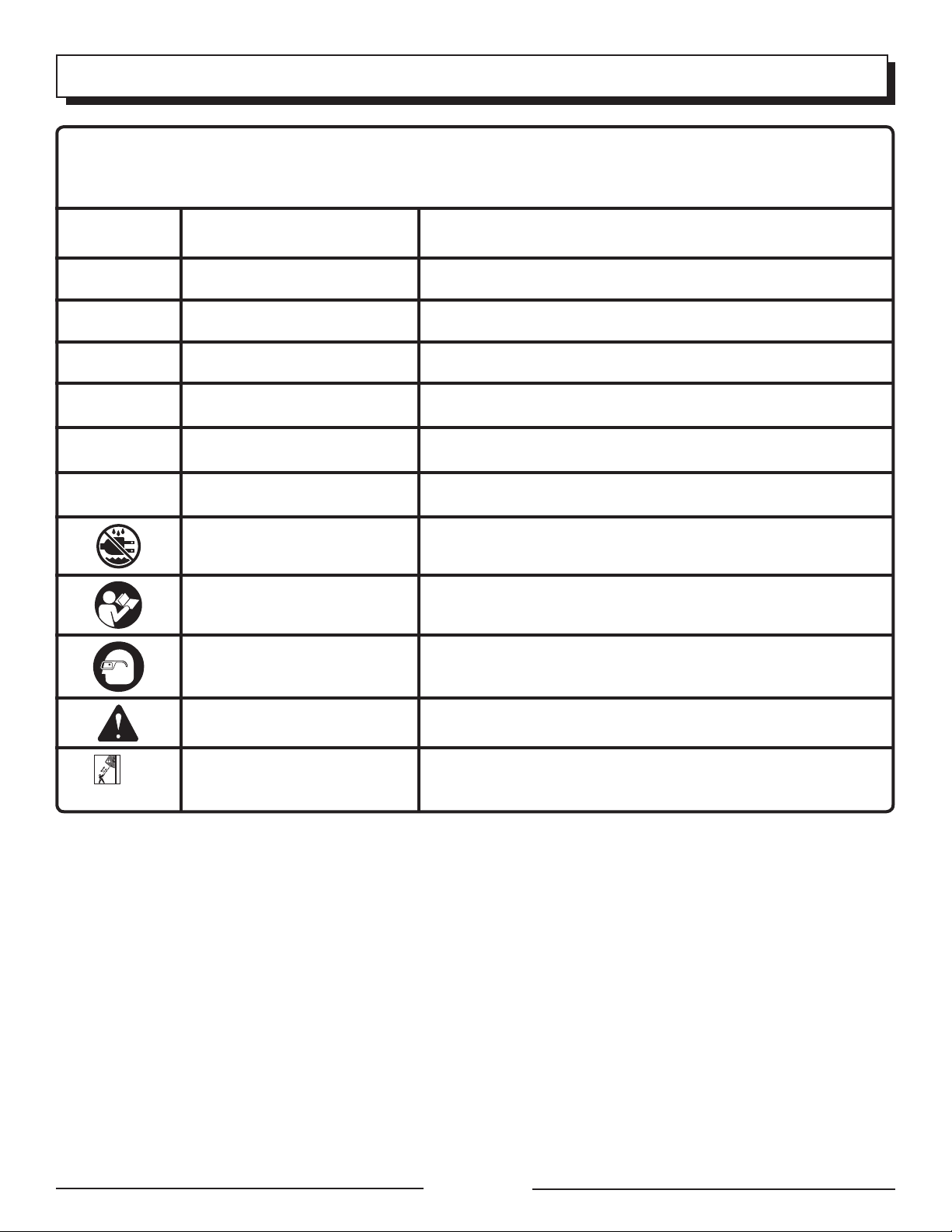
Some of the following symbols may be used on this product. Please study them and learn their meaning. Proper
interpretation of these symbols will allow you to operate the product better and safer.
SYMBOL NAME DESIGNATION/EXPLANATION
V Volts Voltage
A Amperes Current
Hz Hertz Frequency (cycles per second)
W Watt Power
hrs Hours Time
gal Gallon Volume
qt Quart Volume
Wet Conditions Alert Do not expose to rain or use in damp locations.
Read The Operator’s Manual
Eye Protection
Safety Alert Precautions that involve your safety.
Electric Shock
To reduce the risk of injury, user must read and understand
operator’s manual before using this product.
Always wear safety goggles or safety glasses with side shields and,
as necessary, a full face shield when operating this product.
Failure to use in dry conditions and to observe safe practices can
result in electric shock.
Page 5
Page 6
SYMBOLS
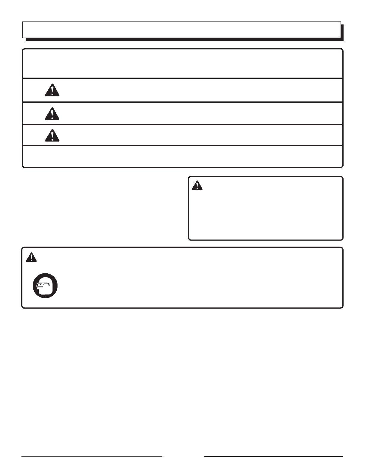
The following signal words and meanings are intended to explain the levels of risk associated with this product.
SYMBOL SIGNAL MEANING
DANGER: Indicates an imminently hazardous situation, which, if not avoided, will
result in death or serious injury.
WARNING: Indicates a potentially hazardous situation, which, if not avoided, could
result in death or serious injury.
CAUTION: Indicates a potentially hazardous situation, which, if not avoided, may
result in minor or moderate injury.
CAUTION: (Without Safety Alert Symbol) Indicates a situation that may result in
property damage.
SERVICE
Servicing requires extreme care and knowledge and should
be performed only by a qualified service technician. For
service we suggest you return the product to your nearest
AUTHORIZED SERVICE CENTER for repair. When servicing, use only identical replacement parts.
To avoid serious personal injury, do not attempt to use this
product until you read thoroughly and understand completely the operator’s manual. If you do not understand
the warnings and instructions in the operator’s manual,
do not use this product. Call Homelite customer service
for assistance.
WARNING:
WARNING:
The operation of any power tool can result in foreign objects being thrown into your eyes, which can
result in severe eye damage. Before beginning power tool operation, always wear safety goggles or safety
glasses with side shields and, when needed, a full face shield. We recommend Wide Vision Safety Mask
for use over eyeglasses or standard safety glasses with side shields. Always use eye protection which
is marked to comply with ANSI Z87.1.
SAVE THESE INSTRUCTIONS
Page 6
Page 7

FEATURES
PRODUCT SPECIFICATIONS
Battery ..................24volt, 17A/Hr sealed maintenance free
No-load Speed ...................................... 3,600 r/min. (RPM)
Cutting Path ............................................................... 20 in.
Height Adjustments ............................. 1-1/2 in. to 3-3/4 in.
Wheel Size ............................................ 7 in. front, 8 in. rear
Weight ........................................................................ 87 lb.
GRASS CATCHER
HEIGHT ADJUSTMENT
LEVER
MOTOR/BLADE
CONTROL
ASSEMBLY
BATTERY
METER
SIDE DISCHARGE
DEFLECTOR
SWITCH
KEY
MULCHING PLUG
CHARGER
Page 7
Fig. 1
Page 8

FEATURES
KNOW YOUR LAWN MOWER
See Figure 1.
The safe use of this product requires an understanding of
the information on the product and in this operator’s manual
as well as a knowledge of the project you are attempting.
Before use of this product, familiarize yourself with all operating features and safety rules.
BATTERY METER
The battery meter measures the amount of charge remaining in the battery.
GRASS CATCHER
The grass catcher prevents grass clippings from being
strewn across your lawn as you mow.
HEIGHT ADJUSTMENT LEVER
The height adjustment lever provides cutting height
adjustments.
MOTOR/BLADE CONTROL ASSEMBLY
The motor/blade control, located on the upper handle of the
mower, engages and disengages the motor and blade.
MULCHING PLUG
Your mower is equipped with a mulching plug that cuts and
recuts the grass for finer clippings.
SWITCH KEY
The switch key must be inserted before the mower can be
started.
SIDE DISCHARGE DEFLECTOR
Use the side discharge deflector on your mower when
the grass is too high to mulch or when side discharging is
preferred. The grass clippings produced when using the
side discharge deflector are noticeably larger than those
produced when using the mulching plug.
ASSEMBLY
UNPACKING
This product requires assembly.
Carefully remove the product and any accessories from
the box. Make sure that all items listed in the packing list
are included.
Inspect the product carefully to make sure no breakage
or damage occurred during shipping.
Do not discard the packing material until you have care-
fully inspected and satisfactorily operated the product.
If any parts are damaged or missing, please call
1-866-457-5888 for assistance.
PACKING LIST
Mower
Switch key
Side Discharge Deflector
Mulching Plug
Grass Catcher
Charger
Operator’s Manual
WARNING:
If any parts are damaged or missing do not operate this
product until the parts are replaced. Failure to heed this
warning so could result in serious personal injury.
WARNING:
Do not attempt to modify this product or create accessories not recommended for use with this product. Any
such alteration or modification is misuse and could result
in a hazardous condition leading to possible serious
personal injury.
WARNING:
Do not insert switch key until assembly is complete.
Failure to comply could result in accidental starting and
possible serious personal injury.
Page 8
WARNING:
To prevent accidental starting, do not make any adjustments or installations with the switch key inserted.
Page 9
ASSEMBLY
WARNING:
Never operate the mower without the proper safety devices in place and working. Never operate the mower with
damaged safety devices. Failure to heed this warning can
result in serious personal injury.
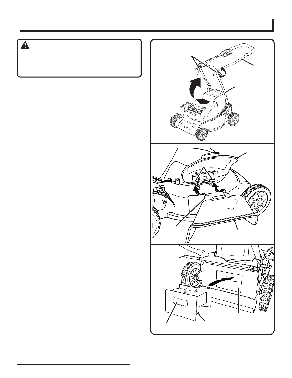
ADJUSTING HANDLE
See Figure 2.
Fully loosen the handle knobs on both sides of the
handle.
Pull up and back on the upper handle to raise the handle
into operating position. Make certain the handles snap
into place securely.
Tighten the handle knobs on both sides of the handle to
secure.
INSTALLING SIDE DISCHARGE DEFLECTOR
See Figure 3.
NOTE: When using the side discharge deflector, do not
install either mulching plug or grass catcher.
Lift the side discharge door.
Align the grooves on the deflector with the pins on the
underside of the door.
Lower the deflector until the hooks on the mower deck
are secured in the openings in the deflector.
Release the deflector and door.
INSTALLING THE MULCHING PLUG
See Figure 4.
NOTE: When using the mulching plug, do not install either
the side discharge deflector or the grass catcher.
Lift the rear discharge door.
Grasp the mulching plug by its handle and tilt at an
approximate 15 degree angle.
Insert the plug into the rear discharge opening.
Lower the rear discharge door.
GROOVE
REAR
DISCHARGE
DOOR
HANDLE KNOBS
PINS
HOOKS
OPENINGS
SIDE DISCHARGE
DEFLECTOR
UPPER
HANDLE
LOWER
HANDLE
Fig. 2
SIDE
DISCHARGE
DOOR
Fig. 3
Page 9
HANDLE
MULCHING
PLUG
REAR
DISCHARGE
OPENING
Fig. 4
Page 10

ASSEMBLY
INSTALLING THE GRASS CATCHER
See Figure 5.
NOTE: When using the grass catcher, do not install either
the side discharge deflector or the mulching plug.
Lift the rear discharge door.
Lift the grass catcher by its handle and place under the
rear discharge door so that the hooks on the grass catcher
are seated on the door rod.
Release the rear discharge door. When installed correctly,
the hooks on the grass catcher will extend through the
openings on the rear discharge door.
SETTING BLADE HEIGHT
See Figure 6.
When shipped, the wheels on the mower are set to a
low-cutting position. Before using the mower for the first
time, raise the cutting position to the height best suited for
your lawn. The average lawn should be between 1-1/2 in.
to 2 in. during cool months and between 2 in. and 3-1/4 in.
during hot months.
To adjust the blade height:
To raise the blade height, grasp the height adjustment
lever and move it toward the back of the mower.
To lower the blade height, grasp the height adjustment
lever and move it toward the front of the mower.
GRASS CATCHER
HANDLE
HOOKS
REAR
DISCHARGE
DOOR
DOOR ROD
OPENINGS
Fig. 5
HEIGHT
ADJUSTMENT
LEVER
OPERATION
WARNING:
Do not allow familiarity with this type of product to make you
careless. Remember that a careless fraction of a second is
sufficient to inflict serious injury.
WARNING:
Always wear safety goggles or safety glasses with side
shields when operating this product. Failure to do so could
result in objects being thrown into your eyes, resulting in
possible serious injury.
HIGHEST
BLADE SETTING
WARNING:
Do not use any attachments or accessories not recommended by the manufacturer of this product. The use of
attachments or accessories not recommended can result
in serious personal injury.
APPLICATIONS
You may use this product for the purpose listed below:
Mowing your lawn
Page 10
LOWEST
BLADE
SETTING
Fig. 6
Page 11
OPERATION
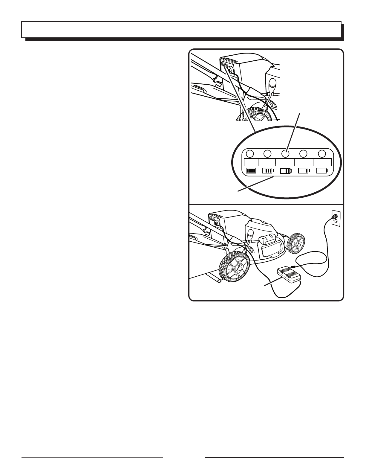
BATTERY METER
See Figure 7.
Since the mower battery is shipped in a low charge condition, the battery must be charged before use. The battery
has 5 LED lights to indicate battery capacity. These lights
will only illuminate when the mower is running.
If 3 GREEN lights illuminate, the battery is charged and ready
for use. 2 green lights are equal to 50-80% charge, while 1
green light is equal to 30-50% charge.
If the AMBER light illuminates, the battery will soon require
charging. It is recommended that the battery be charged at
this point. The battery is at 5-30% charge when the yellow
light illuminates
If the RED light illuminates and/or flashes at any time, the
battery must be charged IMMEDIATELY before use. There
is less than 5% of battery charge when the red light comes
on.
NOTE: When the red light illuminates, you must stop the
mower and charge the battery immediately, or it will reduce
the life of the battery.
LIGHT METER
BATTERY METER
Fig. 7
CHARGING THE BATTERY PACK
See Figures 7 - 8.
The lawn mower comes with a maintenance free, sealed 24
volt storage battery.
Remove the
Charge the battery pack only with the charger provided.
� Allow at least 17 hours of charge time before initial use
of the mower.
Make sure the power supply is normal household voltage,
120 volts, 60 Hz, AC only.
The battery should be charged in a cool, dry place.
To improve battery life, store battery indoors in a controlled
climate. Fully charge battery pack every 30 days.
Since the battery will not develop a memory, it does not
have to be fully discharged before recharging.
2 to 3 initial charging/discharging cycles may be required
to achieve maximum run time/capacity.
When fully charged, the battery can be safely stored in
temperatures down to -40
weeks, before requiring charging
pack every 30 days.
The battery charger should be operated in temperatures
between 23
The battery supplied is sealed, maintenance free and spill
free.
switch key
°F and 104°F
.
°F for a period of up to two
. Fully charge battery
.
TO CHARGE
See Figures 7 - 8.
Remove the
of the reach of children.
Plug the charger connector into the receptacle on the
mower.
Insert the 120 volt plug of the charger into the wall recep-
tacle.
switch key
and store in a secure location out
CHARGER
Fig. 8
Two red lights on the charger should come on, indicating
you have power and the battery is being charged. The red
light should extinguish and a green light will come on when
charging is complete. It takes approximately 17 hours to
charge a fully discharged mower.
STARTING/STOPPING THE MOWER
See Figure 9.
Insert the switch key into the slot on the motor/blade
control assembly.
Rotate the lever release counterclockwise and hold to
allow access to the switch control lever.
�� Pull the switch control lever toward the mower handle and
let go of the lever release. Continue to hold the switch
control lever against the mower handle as you mow.
��� To stop the mower, release the switch control lever.
NOTE: A high-pitched noise and sparking may occur as
the electric motor decelerates. This is normal.
Page 11
Page 12

OPERATION
MOWING TIPS
See Figure 10.
Make sure the lawn is clear of stones, sticks, wires, and
other objects that could damage the lawn mower blades
or motor. Such objects could be accidentally thrown by
the mower in any direction and cause serious personal
injury to the operator and others.
For a healthy lawn, always cut off one-third or less of the
total length of the grass.
� When cutting heavy grass, reduce walking speed to allow
for more effective cutting and a proper discharge of the
clippings.
Do not cut wet grass. It will stick to the underside of the
deck and prevent proper mulching of grass clippings.
New or thick grass may require a narrower cut.
Clean the underside of the mower deck after each use
to remove grass clippings, leaves, dirt, and any other
accumulated debris.
SLOPE OPERATION
Slopes are a major factor related to slip and fall accidents
that can result in severe injury. Operation on slopes
requires extra caution. If you feel uneasy on a slope, do
not mow it. For your safety, do not attempt to mow slopes
greater than 15 degrees.
Mow across the face of slopes, not up and down. Exercise
extreme caution when changing direction on slopes.
Watch for holes, ruts, rocks, hidden objects, or bumps
which can cause you to slip or trip. Tall grass can hide ob-
stacles. Remove all objects such as rocks, tree limbs, etc.,
which could be tripped over or thrown by the blade.
Always be sure of your footing. A slip and fall can cause
serious personal injury. If you feel you are losing your
balance, release the switch control lever immediately.
Do not mow near drop-offs, ditches, or embankments;
you could lose your footing or balance.
SWITCH
SWITCH
KEY
KEY
LEVER
RELEASE
SWITCH
CONTROL
LEVER
KEY
HOLE
SWITCH
CONTROL
LEVER
Fig. 9
Fig. 10
EMPTYING THE GRASS CATCHER
See Figure 11.
Lift the grass catcher by its handle and lift to remove from
mower.
Empty grass clippings.
Lift the rear discharge door and reinstall the grass catcher
as described earlier in this manual.
Page 12
Fig. 11
Page 13

MAINTENANCE
WARNING:
When servicing, use only identical replacement parts.
Use of any other parts may create a hazard or cause
product damage.
WARNING:
Always wear safety goggles or safety glasses with side
shields during power tool operation or when blowing
dust. If operation is dusty, also wear a dust mask.
GENERAL MAINTENANCE
Avoid using solvents when cleaning plastic parts. Most
plastics are susceptible to damage from various types of
commercial solvents and may be damaged by their use. Use
clean cloths to remove dirt, dust, oil, grease, etc.
WARNING:
Do not at any time let brake fluids, gasoline, petroleumbased products, penetrating oils, etc., come in contact
with plastic parts. Chemicals can damage, weaken, or
destroy plastic which may result in serious personal
injury.
Periodically check all nuts and bolts for proper tightness to
ensure safe operation of the mower.
Remove any buildup of grass and leaves on or around the
motor cover. Wipe the mower clean with a dry cloth occa
sionally. Do not use water.
LUBRICATION
All of the bearings in this product are lubricated with a sufficient amount of high grade lubricant for the life of the unit
under normal operating conditions. Therefore, no further
bearing lubrication is required.
At the beginning and end of each mowing season:
� Lubricate the springs on the rear discharge door with light
oil.
� Lubricate the height adjustment lever and related hardware
with light oil.
� Remove the wheels and lubricate the surface of the axle
bolt and the inner surface of the wheel with light oil.
� Remove the blade and blade hub assembly and
lubricate the motor shaft with light oil or engine oil. See
Replacing the Cutting Blade for instructions on removing the blade.
WARNING:
Always protect hands by wearing heavy gloves and/or
wrapping the cutting edges of the blade with rags and
other material when performing blade maintenance.
Failure to heed this warning so could result in serious
personal injury.
WARNING:
Before performing any maintenance, make sure the
mower is unplugged from the power supply and the
switch key is removed. Failure to heed this warning could
result in serious personal injury.
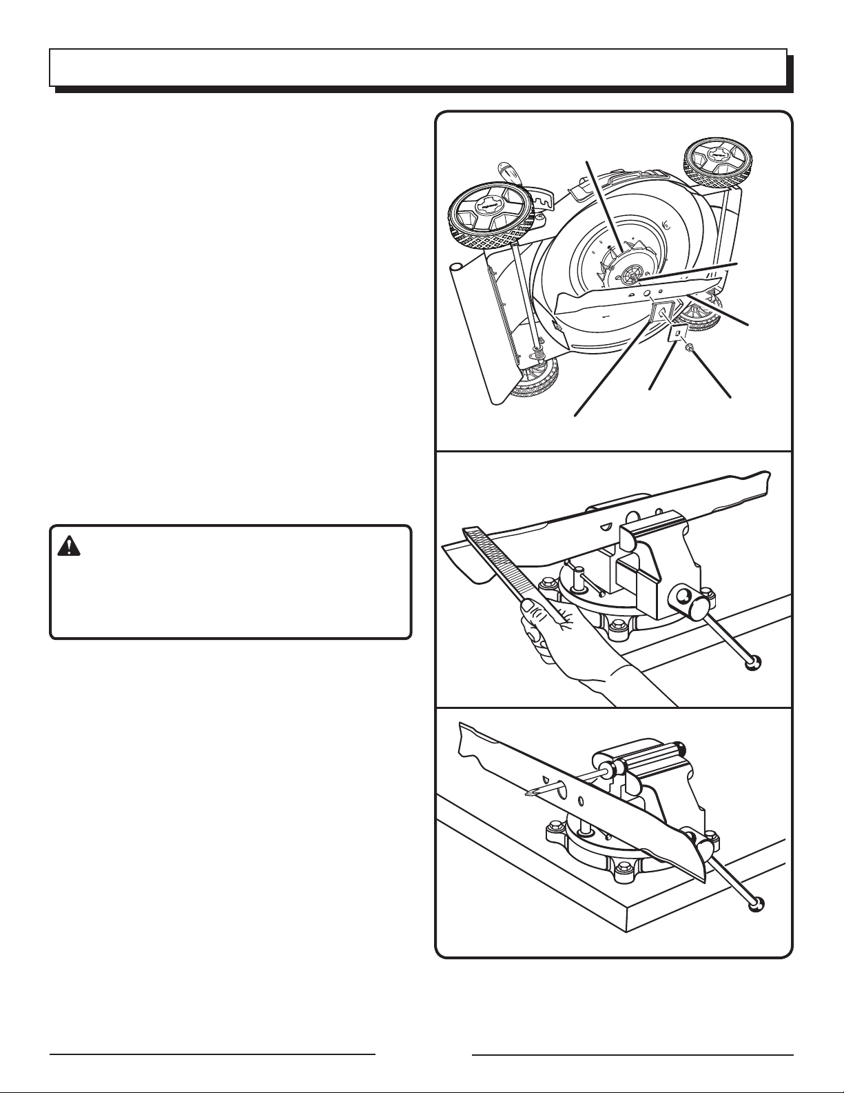
REPLACING THE CUTTING BLADE
See Figure 12 - 13.
Since the mower is equipped with a sealed battery, the
mower can be tipped for maintenance without the danger
of acid spillage.
NOTE: Only use identical replacement blades.
Stop the motor and remove the switch key. Allow blade
to come to a complete stop.
Turn the mower on its side.
� Wedge a block of wood between the blade and mower
deck to prevent the blade from turning.
Loosen the blade nut using a 15 mm wrench or socket
(not provided).
-
Remove the blade nut, spacer, blade insulator, and
blade.
� Make certain the fan assembly is pushed completely
against the motor shaft.
BLADE
WRENCH
Page 13
BLOCK OF WOOD
Fig. 12
Page 14
MAINTENANCE
Place the new blade on the shaft against the fan assembly.
Make sure it is installed with the curved ends pointing
up toward the mower deck and not down toward the
ground.
Replace the blade insulator and spacer, then thread the
blade nut on the shaft and finger tighten.
NOTE: Make certain all parts are replaced in the exact
order in which they were removed.
Torque the blade nut down using a torque wrench
(not provided) to ensure the bolt is properly tightened.
The recommended torque for the blade nut is 450600 in. lbs.
SHARPENING THE BLADE
See Figure 14.
For best mowing performance, the mower blade must be
kept sharp. A dull blade does not cut grass evenly and overloads the motor. Under normal circumstances, sharpening
the blade twice during the mowing season is usually sufficient. However, if your lawn has sandy soil, more frequent
sharpenings may be required.
Following the instructions in the Replacing the Cutting
Blade section, remove the mower blade. DO NOT attempt
to sharpen the blade while it is attached to the mower.
FAN ASSEMBLY
BLADE INSULATOR
SPACER
SHAFT
BLADE
BLADE NUT
Fig. 13
WARNING:
When removing, inspect the blade carefully. If blade is
bent or damaged, replace immediately with a new blade.
Failure to replace a bent or damaged blade could cause
an accident resulting in possible serious injury.
� Using a fine-tooth file or stone, sharpen cutting edges
on both ends of the blade, removing equal amounts of
material from both ends.
BALANCING THE BLADE
See Figure 15.
When sharpening, care should be taken to keep the blade
balanced. An unbalanced blade will cause excessive vibration when the mower is running. This vibration will eventually
cause damage to the mower, especially the motor.
To check the blade balance:
Clamp a screwdriver horizontally in a vise as shown.
NOTE: If a vise is not available, a straight nail can also
be used.
Place the center hole of blade on the screwdriver (or nail)
shank.
If blade is balanced, it will remain in a horizontal position.
If either end of the blade drops downward, sharpen the
heavy side until the blade is balanced.
Fig. 14
Fig. 15
Page 14
Page 15

MAINTENANCE
REPLACING WHEELS
See Figure 16.
To replace a wheel:
Stop the motor and remove the switch key.
� Turn the mower on its side.
Using a flat blade screwdriver, pry off the hubcap.
Remove the cotter pin from the wheel axle, then remove
the wheel.
Replace with new tire and insert new cotter pin to
secure.
Replace hubcap.
STORING THE MOWER
See Figure 17.
Remove the switch key and store in a secure location out
of the reach of children.
Turn mower on its side and clean grass clippings that have
accumulated on the underside of the mower deck.
Wipe the mower clean with a dry cloth.
� Check all nuts, bolts, knobs, screws, fasteners, etc., for
tightness.
� Inspect moving parts for damage, breakage, and wear.
Have repairs made on any damaged or missing parts.
Store mower indoors in a clean, dry place out of the reach
of children.
Do not store near corrosive materials such as fertilizer or
rock salt.
To lower the handle before storing:
Fully loosen the handle knobs on the sides of the handle
and fold the upper handle down.
Push inward on each side of the lower handle, and lift the
sides of the lower handle past the edges of the handle
mounting brackets.
WHEEL AXLE
HANDLE KNOBS
HUBCAP
COTTER PIN
WHEEL
Fig. 16
UPPER
HANDLE
LOWER
HANDLE
BATTERY MAINTENANCE
It is recommended to charge the mower every 2 months for
optimum performance when not in use. If the battery has
been in storage for a long time without recharging, it will be
in a low charge state.
Page 15
Fig. 17
Page 16
TROUBLESHOOTING
Problem Possible Cause Solution
Handle not in position. Carriage bolts not seated properly.
Handle knobs not tightened.
Mower not starting. Battery is low in charge.
Battery is either defective or will not
take a charge.
Mower cutting grass unevenly. Lawn is rough or uneven or cutting
height not set properly.
Mower not mulching properly. Wet grass clippings sticking to the
underside of the deck.
Mower hard to push. High grass, rear of mower housing
and blade dragging in heavy grass, or
cutting height too low.
Adjust the height of the handle and
make sure the carriage bolts are
seated properly.
Tighten handle knobs.
Charge the battery.
Replace the battery.
Move the wheels to a higher posi
tion. All wheels must be placed in the
same cutting height for the mower
to cut evenly.
Wait until the grass dries before
mowing.
Raise cutting height.
-
Mower vibrating at higher speed. Blade is unbalanced.
Bent motor shaft.
CALL US FIRST
For any questions about operating or maintaining your product,
call the Homelite® Help Line!
Your product has been fully tested prior to shipment to ensure
your complete satisfaction.
Balance the blade by grinding each
cutting edge equally.
Stop the motor, disconnect the
power source, and inspe ct fo r
dam age. Hav e repai red by an
authorized service center before
restarting.
Page 16
Page 17
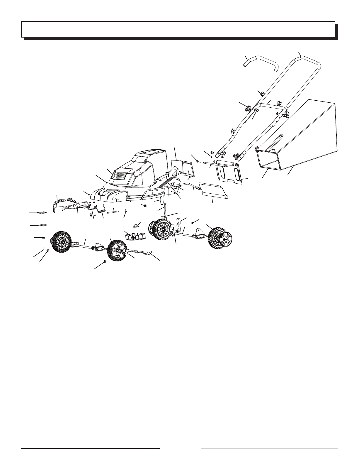
EXPLODED VIEW/PARTS LIST
21
44
48
41
26
42
43
47
45
28
11
12
16
17
30
6
35
36
37
38
40
8
2
39
5
31
15
18
13
7
3
10
14
23
22
46
27
25
24
12
1
4
34
33
29
32
9
20
19
49
Key Part
No. No. Description Qty.
1 3130139-2 Mower motor/deck assy ................... 1
2 3110139-1 Front axle assembly ......................... 1
3 3110239-1 Rear axle assembly .......................... 1
4 3220575 Screw (Pan Hd.) ............................... 4
5 3420191 7 in. front wheel .............................. 2
6 3410391 Wheel cover ....................................4
7 3420291 8 in. rear wheel ............................... 2
8 3331638 Washer (13.5 X 20 x 1.5 in.) ............ 4
9 3290135 Cotter pin ........................................ 4
10 3330639-1 Linkbar ............................................ 1
11 3340137-1 Extension spring ............................ 1
12 3330239-1 Height adjustment assy., Left ...........1
13 3330539-1 Height adjustment assy., Right ......... 1
14 3221637 Bolt (M10 x 20 mm) .......................... 4
15 3220737 Flange nut (M10) ..............................4
16 3410239-1 Height adjustment handle ................ 1
17 3320239-1 Height adjustment shaft ................... 1
18 3330437-1 Spring board ................................... 1
19 3220608 Cap screw (M5 x 15 mm) ............... 4
20 3220439 Lock nut (M5) ................................ 10
21 3410390 Motor vent ...................................... 1
22 3330438 Rear discharge door ......................... 1
23 3320138 Rear discharge pin ........................... 1
24 3220191 Ring washer .....................................2
Page 17
Key Part
No. No. Description Qty.
25 3340138
Rear compression spring .................1
26 3490137 Soft grip .......................................... 1
27 3410238 Mulching plug ................................. 1
28 3420138-1 Rear shield ....................................... 1
29 3330637 Side discharge bracket ................... 1
30 3220136 Flange nut (M6 x 8 mm) .................... 2
31 3320338 Side discharge pin ...........................1
32 3340237 Side compression spring ................. 1
33 3410338 Side discharge door ......................... 1
34 3410438 Side discharge deflector ................... 1
35 3410237 Fan .................................................. 1
36 3410535 Blade insulator ................................. 1
37 3331435 Spacer ............................................. 1
38 3331238-1 Blade ..............................................1
39 3320238 Spindle guard ..................................1
40 3221037 Blade nut (M10 x 1.25 mm) .............. 1
41 3330190 Upper handle .................................. 1
42 3330191 Lower handle .................................. 1
43 3220436 Bolt (M8) .......................................... 2
44 3410835-3 Knob ............................................... 4
45 3221237 Lock nut (M4) .................................. 2
46 3490291 Grass catcher ................................ 1
47 3330291 Grass catcher frame ....................... 1
48 3411135 Cord guide ....................................... 1
49 3320237
“O” ring ...........................................2
Page 18

WARRANTY
LIMITED WARRANTY, BATTERY POWERED MODELS.
This product is manufactured for the Great States Corporation lawn mower company under
license from Homelite Consumer Products Inc. Great States Corporation, Shelbyville, Indiana has
been making lawn mowers for over 100 years and it warrants to the original owner that each new
product and service part is free from defects in material and workmanship and agrees to repair
or replace under this warranty any defective product or part from the original date of purchase
for two (2) years except for the conditions, circumstances and parts listed below.
THIS WARRANTY IS NOT TRANSFERABLE AND DOES NOT COVER:
� The battery for more than one year from date of purchase. Products sold damaged or
incomplete, sold “as is”, sold reconditioned or used as rental equipment.
Delivery, installation or normal adjustments explained in the operator’s manual.
Damage or liability caused by shipping, improper handling, improper installation, incorrect
voltage or improper wiring, improper maintenance, improper modification, or the use of
accessories and/or attachments not specifically recommended.
Repairs necessary because of operator abuse or negligence, or the failure to install, operate,
maintain and store the product according to the instructions in the operator’s manual.
Damage caused by cold, heat, rain, excessive humidity, corrosive environments and materials,
or other contaminants.
Expendable items that become worn during normal use.
Cosmetic defects that do not interfere with tool functionality.
Freight costs from customer to vendor.
Repair and transportation costs of products or parts determined not to be defective.
ANY INCIDENTAL, INDIRECT OR CONSEQUENTIAL LOSS, DAMAGE, OR EXPENSE THAT
MAY RESULT FROM ANY DEFECT, FAILURE OR MALFUNCTION OF THE PRODUCT. Some
states do not allow the exclusion or limitation on how long an implied warranty lasts, so the
above limitations may not apply to you.
ANY NON-RESIDENTIAL USE OR COMMERCIAL USE VOIDS ALL WARRANTIES.
CALL US FIRST !!
Call us first with questions about operating or maintaining your lawn mower at 1-866-457-5888
between 7:30 a.m. – 4:30 p.m. Eastern Standard Time, or send emails to homelite@reelin.com.
Page 18
Page 19

NOTES
Page 19
Page 20

OPERATOR’S MANUAL
20 in. 24 VOLT
CORDLESS LAWN MOWER
UT13122
SERVICE
For parts or service, contact your nearest Homelite authorized service dealer. Be sure to provide
all relevant information when you call or visit. For the location of the authorized service dealer
nearest you, please call 1-866-457-5888 or visit us online at www.homelite.com.
REPAIR PARTS
The model number of this tool is found on a plate or label attached to the housing. Please
record the serial number in the space provided below.
MODEL NUMBER ___________________
SERIAL NUMBER ___________________
UT13122
HOMELITE CONSUMER PRODUCTS, INC.
1428 Pearman Dairy Road
Anderson, SC 29625
Phone 1-866-457-5888
www.homelite.com
987000-039
11-27-06 (REV:00)
 Loading...