

Home Easy HE-440 Installation Instruction
HOME
easy
HE-440 Outdoor Remote
Control 4Gang Kit
RE-INVENTING THE H OME
The HE-440 allows you to control up to 4
separate outdoor electrical products
independently using the HomeEasy
remote control timer, with a maximum
combined load of 3000W.
Features:
-Selectable timer setting
-8 Programmable memory Settings
-Security Mode Setting
HOME
easy
HE200
HE440
-IP56 Weather Proof
-30 Metre Wire Free Range
-CR2032/23A Battery (Included)
-Single and Daily Timer Functions
Product Specification:
4 Gang Remote Control Receiver: HE-440
Input: 230V - 240V ~50Hz
Range: 30 Metres (Open Distance)
Frequency: 433.92MHz
Max Load: 3000W
Remote Control PIR: HE-200
Battery: 23A & CR2032 (Included)
Range: 30Metres (Open Distance)
Frequency: 433.92MHz
Indoor use only
(Combined Resistive load)
IP56 (Lid Closed)
Warning: Never Exceed the Product Specification
INSTALLATION WARNING:
ON INSTALLATION TURN OFF YOUR MAINS ELECTRIC SUPPLY
This product should be fitted by a competent person in accordance with the
instructions listed below and with the relevant clauses of the IEE wiring regulations
BS7671.
For fixed installation only
The HE440 should be used in conjunction with a fused spur connection, all connections
to the socket need to be made as instructed, making sure that the cable used is
appropriate for the installation environment, free from stress & terminals are tightened
fully.
V1.0
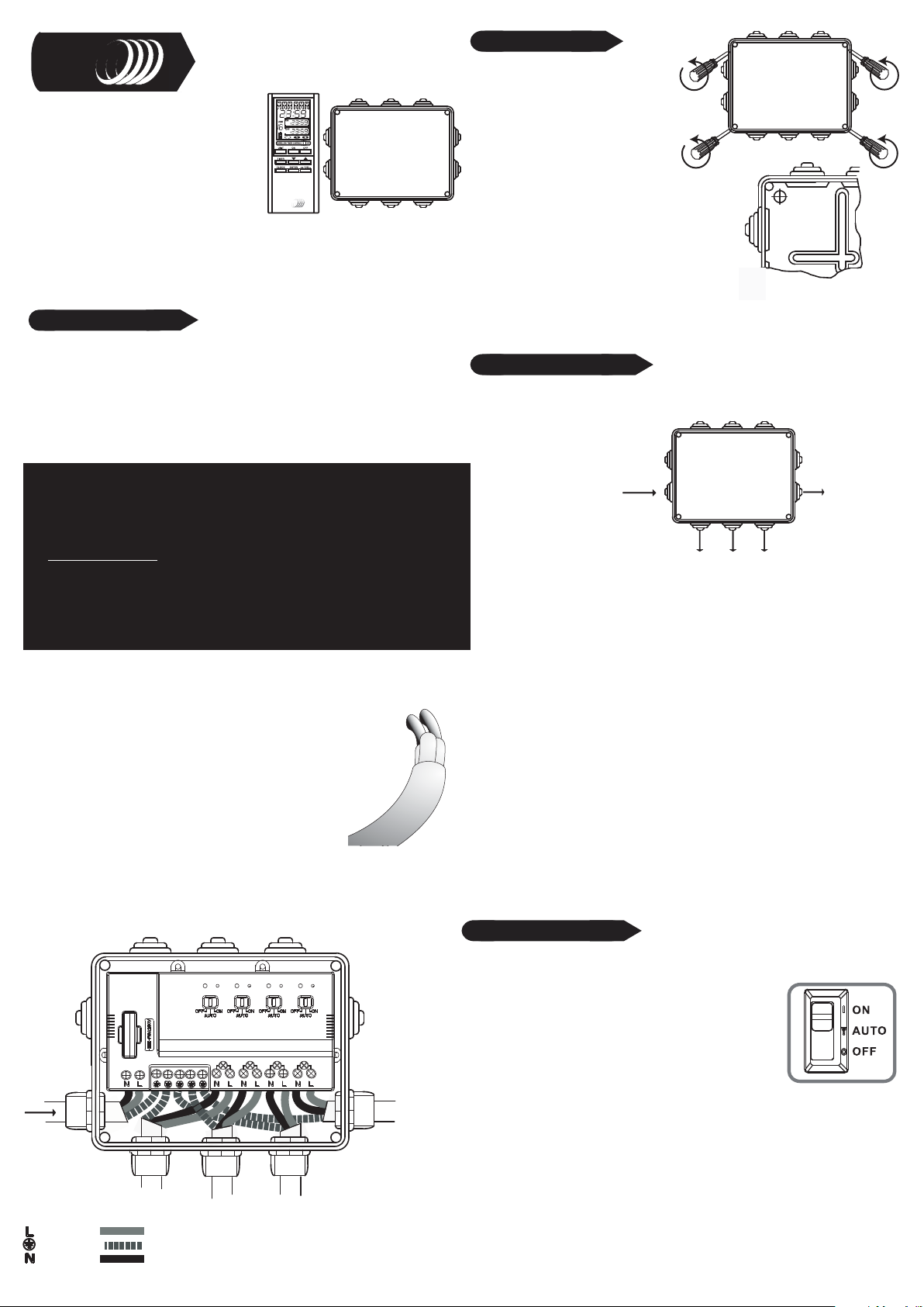
Installation Guide:
1. Remove the front cover by
unscrewing the 4 corner screws as
shown.
2: In the back half of the unit, in all four corners are
purpose made holes for fixing your HE440 to your
intended surface.The HE440 needs to be mounted
onto a flat, vertical surface, free from grease, loose
material and any corrosive substances.We
recommend a house or sturdy garden wall.
3. Using the back half of the unit as a template, mark
all four corners onto your chosen surface. Insert suitable
wall plugs and secure to the wall using number '8' screw
(recommended size - Not included).
Wiring Remote Socket:
On the outdoor enclosure you will see that there are a number of rubber entry spaces
(ëEntry blanksí) on each side, depending on location and wiring setup a number of
these can be removed.
Recommended Setup:
Voltage In:
230-240V ~ 50Hz
Channel 1 Out
Once the entry blanks are
removed, appropriate cable
glands need to be installed (not
included).
Channel 3 Out
Channel 2 Out
Output:
230-240V ~ 50Hz
3000W Combined
Channel 4 Out
Input Power: (See Wiring Diagram)
1: Switch off and isolate the mains power before Installing or altering the
electrocal connections and remove the terminal covers.
2: Send the cable through the gland and into the HE440.
3: Cut back the cable to reveal the 3 separate wires
L= Live Brown
E= Earth Green & Yellow
N= Neutral Blue
4: Now strip each wire, exposing 10mm of its core
5: Insert the exposed core wires into their related terminals
and clamp down by tightening the respective screws.
Replace the terminal covers and tighten the cabel glands,
making sure wall wires are secure.
6. Reconnect the mains power, the HE440 is now ready for programming
(See Pairing/Deleting with Remote).
Replace the front cover and tighten the screws.
Wiring Diagram:
Input Power
230 - 240V ~50HZ
Accessory Output 4
If installing the HE440 with conduit from the sides or top attachment, a 5mm hole
must be drilled through the bottom left drainage hole.This will allow for any
condensation forming in the conduit, to drain out.
Caution: opening the drainage hole will affect the IP rating of the product. Ensure that
jetted water is not directly sprayed onto the unit.
Do Not drill out the drainage hole when installing the Outdoor socket into a dusty
environment. Always install the unit via the bottom cable entry, making sure that a 5mm
hole is drilled into the lowest point in the conduit system.
WARNING:
You MUST install an earth cable between the origin of the installation and the earth
terminal of the outdoor socket.This must be insulated inside a sleeve protector within
the conduit.
If using metal conduit, earth continuity must be maintained between conduits. Seal
Conduit and conduit entry with a non setting conduit sealant. Purchasable form you
local electrical retailer.
Operating Mode:
Each Acessory Output Channel can operate in 3 seperate modes, use the slide
switch on each channel to select the mode setting.
AUTO:Allows the Remote Control to switch on/off
the HE440. See Pairing/Deleting with Remote
ON: Sets the Outdoor socket as a standard outdoor socket.
USE THIS OPTION WHEN USING GARDEN
MACHINERY SUCH AS A LAWNMOWER OR HEDGE CUTTERS.
OFF: An additional safety feature of the HE440 is the ability to switch off the
power as per a normal socket.
Unused accessory Channels should be set to OFF
Accessory Output 1 Accessory Output 2 Accessory Output 3
= Live Brown
= Earth Green & Yellow
= Neutral Blue

Pairing/Deleting with Remote Control:
PLEASE VIEW PROTOCOL SELECTING
Up to Six remote control units can be paired with each HE440 Accessory
Output Channel.To program a channel press the "Learn" button e.g.
accessory output channel 1.
The LED will start to flash,
now press the "ON" button
on the remote control, the
LED will stop flashing and the
acessory output will switch
"ON/OFF".
Learn
Button
LED
Accessory Ouput
Channel 1
The units are now paired
together, you can test this by
pressing the selected
"ON/OFF" button
Always refer to the original instruction when using with additional
products
Deleting Remote Control:
To delete a remote control that has been paired with a Accessory Output
Channel, simply press the "Learn" button .The LED will start to blink; press the
"Off" button on the remote control, the LED will blink twice to confirm that the
remote control has been removed from the receiver sockets memory.
Channel reset:
To delete all the remote control units from the memory of the Accessory
Output Channel, hold the "Learn" button for more than 6 seconds, the LED will
start to blink continuously. Press the learn button again, the LED will blink
twice to confirm the deletion of all remote controls form the receiver memory.
Contact: Helpline: 0845 2301 231
Contact Details:
C H Byron
34, Sherwood Rd
Aston Fields
Bromsgrove
B60 3DR
Tel: 0845 2301231
Fax: 01527 557701
Web: www.chbyron.com
E-mail:
support@chbyron.com
R&TTE
APPROVED
A
B
DK
FIN
F
D
GR
LT
CH Byron Electrical United Kingdom. www.chbyron.com
433MHz
0560
IRL
UK
I
BG
L
CZ
NL
EST
P
E
S
SLO
H
CH
IS
LV
RO
CODE
REMOTE CONTROL DISPLAY (2)
a.Code number d.ON time g.Unit number
b.Memory space number e.OFF time h.Battery level
c.Real time f.Mode setting i.Signal sent
REMOTE CONTROL BUTTONS (3)
a.CODE (MUST BE 3) e.ENTER key
b.ON and OFF select f.CLOCK setting
c.Up/Down select g.TIMER setting
dPause/DEL key
BATTERY INSTALLATION
-Open the battery compartment by sliding its cover off (4a)
-At first Insert CR2032 3V battery; mind the + and (4b)
-Insert A23 12V battery; mind the + and (4c), then close the cover back in
Its place.
CLOCK SETTING
-Press and hold CLOCK button (3f). Hour starts Flashing (5).
-Select the hour setting with the Up/Down buttons (3c), press ENTER (3e)
to confirm.
-Select the minute setting with the Up/Down buttons, press ENTER to
confirm.
PROTOCOL SELECTING (6)
-Press CODE key (3a) to switch to code number 3 (2a).
M
N
SK
PL
PLEASE NOTE: THE CODE MUST BE SET ON
3 TO OPERATE THE HE44O RECEIVER.
TIMER PROGRAMMING
-Press and hold the TIMER button (3g). The home screen will change into
timer programming mode (8).
-First you have to select which memory space (2b) you want to use by
pressing the Up/Down buttons (3c) and press ENTER (3e).Note: there are
8 memory spaces available.
-Now select the unit number (2g) you want to switch by pressing the
Up/Down buttons, press ENTER to confirm.Note: there are 15 unit
numbers.
-Change the turn on hour settings by using the Up/Down buttons, press
ENTER. Now change the minute settings and press ENTER.
-Change the turn off hour and minute settings In the same way as above.
Press ENTER to confirm.
-Now you can select between 3 mode settings (2f):
Daily Timer - will switch on and off every day at the set times.
Single Timer - will switch on and off only one time.
Security Timer - will switch on and off every day at random
times, varying from 40 minutes before to 120 minutes after switch on
time and 40 minutes before and 180 minutes after switch off time. Press
ENTER to confirm.
- The remote will now go back to selecting the memory space. Press
TIMER button to return to home screen, or wart for the device to switch
back
automatically after some time.
PAUSING SET TIMERS
-Press and hold the TIMER button (3g).
-Select which memory space (2g) you want to pause, by pressing the
Up/Down buttons (3c).
-Press Pause button (3d). Selected memory space will appear with sign
(for example [1]). Press ENTER button (3a) to confirm pausing.
-Press TIMER button to exit or wait for device to switch back automatically after some time.
-To stop pausing use exactly the same way.
DELETING SET TIMERS
-Press and hold the TIMER button (3g).
-Select which memory space (2g) you want to clear, by pressing the
Up/Down buttons (3c).
-Press and hold the DEL button (3d) until both ON (2d) and OFF (2e)
times, mode (2f) and unit number (2g) start flashing. Press ENTER button
(3e) to confirm deleting.
-Press TIMER button to exit or wait for device to switch back automatically after some time.
TIPS
-The transmitting range is shortened when signal needs to go through
walls and floors
-Multiple switches can have the same unit code, these will the simultaneously switch on and off.
-Always give dimmers their own unit code, as to set them up separately.
-Metal will have a negative influence on the transmitting range.
-Make sure code is set on 3. (6)
To enable the screen lock hold both ENTER and DEL buttons for 5
seconds. A lock symbol will now appear to disable the lock repeat the
process and the lock will disappear.
 Loading...