

Home Automation INC. Omni IIe Owner's Manual

HOME AUTOMATION, INC.
Owner's Manual
Document Number 20R00-50 Rev. 2.11
January, 2006

Copyright © 2001-2006 Home Automation, Inc.
All Rights Reserved

Contents
INTRODUCTION........................................................................................................................................... 1
Underwriter's Laboratories (UL) Listing .........................................................................................................................................1
OVERALL DESCRIPTION.......................................................................................................................... 2
Console Operation ...........................................................................................................................................................................2
Normal Top-Level Display..............................................................................................................................................................3
Display Menus.................................................................................................................................................................................3
Main Menu..................................................................................................................................................................................4
Error Beeps.................................................................................................................................................................................4
Trouble Beeps.............................................................................................................................................................................4
Confirmation Beep......................................................................................................................................................................5
Cancel.........................................................................................................................................................................................5
Time Out.....................................................................................................................................................................................5
Areas................................................................................................................................................................................................5
Omni IIe Maintenance.....................................................................................................................................................................5
SECURITY SYSTEM OPERATION........................................................................................................... 6
Disarming the Security System and Silencing Alarms....................................................................................................................6
Arming the Security System............................................................................................................................................................6
Using Shortcut Keys........................................................................................................................................................................7
Quick Arm.......................................................................................................................................................................................8
Bypassing Zones..............................................................................................................................................................................8
Auto-Bypass ...............................................................................................................................................................................8
Restoring Zones...............................................................................................................................................................................8
#=GOTO.....................................................................................................................................................................................9
What To Do When You Come Home..............................................................................................................................................9
What Happens When the Alarm is Activated..................................................................................................................................9
Burglar Alarm Activated ............................................................................................................................................................9
Fire Alarm Activated................................................................................................................................................................10
Gas Alarm Activated ................................................................................................................................................................10
Emergency Keys............................................................................................................................................................................10
Police Emergency.....................................................................................................................................................................11
Fire Emergency.........................................................................................................................................................................11
Auxiliary Emergency ................................................................................................................................................................11
Duress Code Entered or Duress Alarm Activat ed.......................................................................................................................... 11
Alarm Reset...................................................................................................................................................................................11
Alarm Cancel.................................................................................................................................................................................11
Trouble Indications........................................................................................................................................................................12
Codes .............................................................................................................................................................................................12
Master Code..............................................................................................................................................................................12
Manager Code...........................................................................................................................................................................13
User Code .................................................................................................................................................................................13
Duress Code...................................................................................................................................................................................13
Panic Switches...............................................................................................................................................................................13
Area Arming..................................................................................................................................................................................13
GOTO Area....................................................................................................................................................................................14
Testing Your System......................................................................................................................................................................15

CONTROL .................................................................................................................................................... 16
Control Commands........................................................................................................................................................................16
About UPB.....................................................................................................................................................................................16
HAI Lighting Control (HLC) Format.............................................................................................................................................17
About Rooms............................................................................................................................................................................17
About Room Controllers...........................................................................................................................................................17
Room Controller LED Indicators..............................................................................................................................................17
About House Controllers ..........................................................................................................................................................18
About CentraLite ...........................................................................................................................................................................18
About Lutron RadioRA..................................................................................................................................................................18
About ALC.....................................................................................................................................................................................19
ALC Module Types ..................................................................................................................................................................19
About X-10 ....................................................................................................................................................................................19
House Codes..................................................................................................................................................................................19
Unit Numbers.................................................................................................................................................................................20
Scrolling Through Names..............................................................................................................................................................20
Controlling Units ...........................................................................................................................................................................20
Controlling a Room of HLC Lighting.......................................................................................................................................20
Configuring Lighting Scenes in an HLC Room....................................................................................................................21
Controlling Individual Lighting Loads in an HLC Room or UPB Units..................................................................................21
Controlling CentraLite Units ....................................................................................................................................................21
Controlling RadioRA Units ......................................................................................................................................................22
Controlling ALC or X-10 Units................................................................................................................................................22
Ramp Command (ALC)........................................................................................................................................................23
Controlling Compose Units ......................................................................................................................................................23
Scene Command (Compose).................................................................................................................................................24
Timed Commands..........................................................................................................................................................................24
Status of a Unit...............................................................................................................................................................................24
Internal Flags .................................................................................................................................................................................24
Controlling Outputs........................................................................................................................................................................25
All On / Off....................................................................................................................................................................................25
All Lights On ............................................................................................................................................................................26
All Off.......................................................................................................................................................................................26
Leviton Scene Control ..............................................................................................................................................................26
Scene.....................................................................................................................................................................................26
Scene Commands..................................................................................................................................................................27
Scene Set Command.............................................................................................................................................................27
Scene On Command .............................................................................................................................................................27
Scene Off Command.............................................................................................................................................................27
UPB Links.................................................................................................................................................................................27
Activating and Deactivating Links........................................................................................................................................28
Setting a Link (Lighting Scenes)...........................................................................................................................................28
Executing Phantom Buttons......................................................................................................................................................28
Executing CentraLite Scenes....................................................................................................................................................28
Buttons...........................................................................................................................................................................................29
Temperature Control......................................................................................................................................................................29
HAI RC-Series Thermostats ..........................................................................................................................................................30
Programmable Energy Saver Modules (PESMs)...........................................................................................................................31
Freeze Alarms...........................................................................................................................................................................33
Indoor and Outdoor Temperature..............................................................................................................................................33
Temperature Control of Appliances..........................................................................................................................................34
Temperature Alarms ......................................................................................................................................................................34
Humidity........................................................................................................................................................................................34

Status..............................................................................................................................................................................................35
Configuring HLC Devices........................................................................................................................................................35
Configuring HLC Devices using an Omni Console..............................................................................................................35
Configuring HLC Devices using an OmniTouch Touchsc re e n............................................................................................36
Setup Mode for HLC Devices...................................................................................................................................................36
Event Log.......................................................................................................................................................................................38
Show Events .............................................................................................................................................................................38
Messages........................................................................................................................................................................................39
Show Message..........................................................................................................................................................................39
Log Message.............................................................................................................................................................................40
Clear Message...........................................................................................................................................................................40
Say Message .............................................................................................................................................................................40
Phone Message .........................................................................................................................................................................40
Send Message (Pro-Link) .........................................................................................................................................................40
TELEPHONE CONTROL .......................................................................................................................... 42
Telephone Interface .......................................................................................................................................................................42
In-House Phones............................................................................................................................................................................42
Remote Phones ..............................................................................................................................................................................42
Phone Access Denied - Remote Lockout.......................................................................................................................................43
Alternate Method...........................................................................................................................................................................43
Main Menu.....................................................................................................................................................................................43
1 - Control......................................................................................................................................................................................44
2 - Security.....................................................................................................................................................................................44
GOTO Area ..............................................................................................................................................................................44
3 - Button.......................................................................................................................................................................................44
4 - All.............................................................................................................................................................................................44
5 - Temperature..............................................................................................................................................................................44
6 - Status........................................................................................................................................................................................45
7 - Events.......................................................................................................................................................................................45
8 - Phone........................................................................................................................................................................................46
9 - Good-Bye .................................................................................................................................................................................46
Panic Button over the Phone (# # # # # #).....................................................................................................................................46
Emergency Dial-Out......................................................................................................................................................................47
Digital Dialer .................................................................................................................................................................................47
Voice Dialer...................................................................................................................................................................................47
How the Omni IIe Voice Dialer Works....................................................................................................................................47
What the Omni IIe Voice Dialer Does......................................................................................................................................48
What You Hear - If Your Omni IIe Calls You..........................................................................................................................48
Entering the Code.....................................................................................................................................................................48
PC Access....................................................................................................................................................... 49
Built-In Ethernet Port.....................................................................................................................................................................49
Controller IP Address, Port Number, and Encryption Key............................................................................................................49
Omni IIe Ethernet Connections......................................................................................................................................................49
Connecting to Network via PC Access..........................................................................................................................................49
Dynamic DNS................................................................................................................................................................................50

SETUP............................................................................................................................................................ 52
Configuration and Advanced Control Programming (ACP) ..........................................................................................................52
Set Up Codes..................................................................................................................................................................................52
Authority Level.........................................................................................................................................................................52
AUTHORITY...........................................................................................................................................................................52
1 = Master.................................................................................................................................................................................52
2 = Manager..............................................................................................................................................................................52
3 = User.....................................................................................................................................................................................52
Access Areas.............................................................................................................................................................................52
Duress Code..............................................................................................................................................................................53
Set Up Time...................................................................................................................................................................................53
Advanced Control Programming (ACP)........................................................................................................................................54
1 = Add Programs.....................................................................................................................................................................54
2 = Show Programs...................................................................................................................................................................54
3 = Delete All Programs ...........................................................................................................................................................56
Edit Programs.................................................................................................................................................................................56
Edit Programs When......................................................................................................................................................................57
Times Programs........................................................................................................................................................................57
Button and Event Programs ...........................................................................................................................................................58
Control Unit / Switch Press Event Buttons..............................................................................................................................58
Security Mode Event Buttons...................................................................................................................................................59
Zone Event Buttons...................................................................................................................................................................60
All On/Off Event Buttons.........................................................................................................................................................60
UPB Link Event Buttons.......................................................................................................................................................61
Alarm Event Buttons.................................................................................................................................................................61
X-10 Event Buttons...................................................................................................................................................................61
Miscellaneous Event Buttons....................................................................................................................................................62
Message Event Buttons (Pro-Link)...........................................................................................................................................62
Switch Press Event Buttons (CentraLite)..................................................................................................................................63
Edit Program Command.................................................................................................................................................................63
Program Control Commands ....................................................................................................................................................63
Unit Toggle Command..........................................................................................................................................................64
Program Security Commands ...................................................................................................................................................64
Program Button Commands......................................................................................................................................................65
Program All On / All Off Commands .......................................................................................................................................65
Program Video Commands*.....................................................................................................................................................65
Program Temperature Commands............................................................................................................................................65
Program Energy Cost................................................................................................................................................................65
Program Message Commands...................................................................................................................................................66
Edit Program Condition.................................................................................................................................................................66
Program Control Conditions.....................................................................................................................................................66
Program Security Mode Conditions..........................................................................................................................................67
Program Zone Conditions.........................................................................................................................................................67
Program Time Clock Conditions ..............................................................................................................................................67
Program Other Conditions........................................................................................................................................................67
Set Up Dial.....................................................................................................................................................................................69
Telephone Access .....................................................................................................................................................................69
Answer Outside Call.............................................................................................................................................................69
Remote Commands...............................................................................................................................................................69
Rings Before Answer................................................................................................................................................................69
Dial Type ..................................................................................................................................................................................69
My Phone Number....................................................................................................................................................................69
Dial Out Number 1....................................................................................................................................................................70
Dial Out Numbers 2-8...............................................................................................................................................................70
Dial Order.................................................................................................................................................................................70

Set Up Arming...............................................................................................................................................................................71
Entry Delay...............................................................................................................................................................................71
Exit Delay.............................................................................................................................................................................71
Audible Exit Delay ...................................................................................................................................................................71
Entry/Exit Chime......................................................................................................................................................................71
Perimeter Chime.......................................................................................................................................................................71
Enable Quick Arm....................................................................................................................................................................72
Enable Auto Bypass..................................................................................................................................................................72
All On For Alarm......................................................................................................................................................................72
Beep On Trouble.......................................................................................................................................................................72
Set up Miscellaneous.....................................................................................................................................................................72
High Security Mode..................................................................................................................................................................72
Announce Alarms.....................................................................................................................................................................72
Enable Freeze Alarm ................................................................................................................................................................73
Flash For Alarm........................................................................................................................................................................73
House Codes 1-4 Format ..........................................................................................................................................................73
House Codes 1-4 All Off..........................................................................................................................................................73
Time Clocks..............................................................................................................................................................................74
Latitude, Longitude, and Time Zone ........................................................................................................................................75
Daylight Savings.......................................................................................................................................................................75
Controller IP Address ...............................................................................................................................................................76
Controller Port Number............................................................................................................................................................76
Encryption Key.........................................................................................................................................................................77
Set Up Names................................................................................................................................................................................77
Set Up Voice ..................................................................................................................................................................................78
Set Up Address ..............................................................................................................................................................................78
UNDERWRITER'S LABORATORIES REQUIREMENTS................................................................... 79
FIRE ESCAPE PLANNING..........................................................................................................................................................79
FEDERAL COMMUNICATION COMMISSION NOTICE: ................................................................. 80
CANADIAN INDUSTRY CANADA NOTICE..........................................................................................81
APPENDIX A - DIAL OUT PLANNER..................................................................................................... 82
INSTRUCTIONS TO CALLED PARTY......................................................................................................................................83
APPENDIX B - TEXT DESCRIPTION CHARACTER CODES............................................................ 84
APPENDIX C - VOICE DESCRIPTION CODES.................................................................................... 85


INTRODUCTION
Thank you for purchasing your new Omni IIe automation system. You are about to enjoy a new feeling of security, comfort,
convenience, and control. Omni IIe coordinates lighting, heating and air, security, scenes, and messages based on your lifestyle
and schedule.
Please take a few moments to become familiar with all of the features of your system by reviewing this manual. Please keep this
manual on file for future reference.
It is recommended that you also review the installation and operating instructions provided with your smoke and gas detectors (if
used in your system). If you do not have a copy of these documents, ask your installer - See Underwriter's Laboratories
Requirements.
In the event that there are any questions, please call your installer first. If you need assistance directly from the manufacturer, call
us at (985) 624-2606, between the hours of 9:00 AM and 5:00 PM Central Time, Monday-Friday. We will be happy to assist you.
When calling, please have the model and serial number of your unit, which can be found on the inside of the controller.
For your convenience, we suggest that you record this information:
MODEL NUMBER: ________________________
SERIAL NUMBER: ________________________
Underwriter's Laboratories (UL) Listing
The 20A00-50, -51, and -52 Omni IIe controllers and consoles have been tested and Listed by UL for the following applications:
• UL 985 - Household Fire Warning System Units
• UL 1023 - Household Burglar Alarm System Units (Grade A)
The 20A00-51 Omni IIe controller has also been tested and Listed by UL for the following applications:
• UL 365 - Police Station Connected Burglar Alarm Units and Systems (Grade A)
• UL 609 - Local Burglar Alarm Units and Systems (Grade A)
• UL 1610 - Central Station Burglar Alarm Units (Grade B, C)
In a UL Listed Installation, failure to operate and program the system as described in this manual is a violation of the Listin g
Mark.
See Underwriter's Laboratories Requirements for more information.
Page 1
OVERALL DESCRIPTION
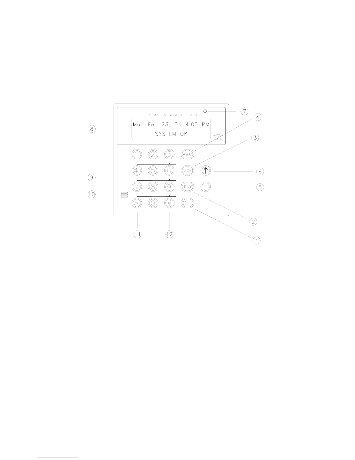
Console Operation
The console is designed with everything that is necessary for you to program and operate your Omni IIe control and security
system. Because we feel that it is very important for you to feel comfortable with the operation of your Omni IIe, we recommend
that you start by becoming familiar with your console.
The OFF (1), DAY (2), NIGHT (3), and AWAY (4) keys are called shortcut keys. This means that you may press these keys to
go directly to that function without having to go into one of the "hidden" menus.
OMNI
CONTROL
ALL
TEMP
STATUS
POL
FIRE
BUTTONS
SECURITY
L
MESSAGE
EVENTS
SETUP
AUX
CANCEL
MENU
1- ' OFF '
The ' OFF ' key is used to disarm (deactivate) the security system, reset the fire and emergency alarms, and silence all sirens and
sounders.
2- ' DAY '
The ' DAY ' key is used to arm the security system in the Day mode. In the Day mode, the perimeter zones (doors and windows)
are protected, however, the interior zones are not armed so that you may move about freely inside. In this mode, there is an entry
delay on entry-exit zones.
3- ' NIGHT '
The ' NIGHT ' key is used to arm the security system in the Night mode. In the Night mode, the doors, windows, and nonsleeping area motion detectors are armed. In this mode, there is no entry delay so the alarm will be activated immediately if any
zone is violated.
4- ' AWAY '
The ' AWAY ' key is used to arm the security system in the Away mode. In the Away mode, all zones (doors, windows, motions,
etc.) are armed. There is an entry delay on entry-ex it zones, so that you can disarm the system when you return through the door.
5- Down Arrow
The Down Arrow key is used to scroll through menus and lists. The down arrow is used to scroll down the list fro m first to last
(for example, when the first program is being displayed, pressing the down arrow will cause the next program to be displayed).
Page 2

6- UP ARROW
The Up Arrow key is used to scroll through menus and lists. The Up Arrow is used to scroll back through a list (f or example, if
you have already used the down arrow to scroll to an item, the Up Arrow will bring you back to a previous item).
7- CONSOLE LED
The Console LED is used to indicate whether the security system is currently armed or disarmed. If armed in any security mode,
the LED is set to red. If the system is disarmed, the LED is set to green. The LED flashes when a Message is displayed.
8- CONSOLE DISPLAY
The Console Display is used to show the current security mode and to give useful information that will guide you through normal
operations of your Omni IIe control and security system.
9- CONSOLE KEYPAD
The Console Keypad is used to enter user codes for arming, disarming, bypassing, and restoring zones. In some cases, the keys
(0-9) are assigned to different functions. From the top-level display, each key functions as a menu choice.
10- CONSOLE BEEPER
The Console Beeper is used to confirm a keystroke, alert user of errors and troubles, and sound upon entry and exit delays.
11- ' * ' KEY
The ' * ' Key is used to cancel and return the display to the previous menu. When you are entering a number, ' * ' will cancel the
previously entered digits and will prompt you to reenter the number.
12- ' # ' KEY
The ' # ' Key is used to enter or confirm a selection. It may also be used to display a menu or to offer you additional choices.
Normal Top-Level Display
In its normal state, the console display will show the day, date, and time on the top line, and the system status on the bottom line.
If all doors, windows, sensors, etc. are closed, no zones are bypassed, and if there are no troubles, the bottom line will show
"SYSTEM OK" as seen below:
Thu Feb 23, 06 4:00 PM
SYSTEM OK
If one of the doors, windows, motion, or other detector connected to the Omni IIe is open, or has detected motion, the bottom line
of the display will say, "ZONE NAME NOT RDY".
For example, the display will show, "FRONT DOOR NOT RDY".
If the zone name has not been entered during set up, the display will give the zo ne number and zone type. This display will
remain for 2 seconds, then the next zone not ready, in trouble, or bypassed will be displayed.
Display Menus
The system has been designed to be easy to operate. Whenever you press a key on the console, the top line of the display will
indicate what you are doing. To the right of that is your selection or current setting. The bottom line will show a menu of your
next options. To the lower right corner of the display is the direction arrow(s). Where possible, the up (
headed () arrow characters are shown on the console display to indicate which arrow keys may be pressed at that time.
↑), down (↓), and two-
Page 3

When using the arrow keys to scroll through lists of areas, buttons, codes, temperature zones, units, or zones, only the named
items are displayed. If no text description has been given to an item, it will be skipped over when scrolling through that list. You
can still enter any item number to access it directly, and then scroll up and down among the named items. To look at another
specific item, simply enter the item number followed by the Down Arrow key.
In some cases, the keypad keys (0-9, *, #) are assigned to different functions or menus. A key assignment is indicated by the
character key directly in front of the new function on the bottom line of the display. For example, if the bottom line says,
"2=DELETE", you may press the 2 key to delete. From the top-level display, each key functions as a menu choice. Simply press
the appropriate key and you will enter that menu.
Main Menu
The main menu is entered from the top-level display by pressing the ' # ' key. This menu d isplays all o f the fun ctio n s that you can
perform from the console. It is not necessary to display the main menu before selecting a function if the number for the desired
menu item is known. The following menu choices are available:
1=CONTROL 2=SECURITY
3=BUTTON 4=ALL
↓
5=TEMP 6=STATUS
7=EVENTS 8=MESSAGE
9=SETUP
↑
Menu 1 - Selects Control functions for controlling lights and appliances.
Menu 2 - Selects Security functions (arming, disarming, bypassing, and restoring).
Menu 3 - Allows a Button (macro) to be activated.
Menu 4 - Selects All Lights On / All Units Off commands and Leviton Scene Control commands.
Menu 5 - Allows Temperature control for Thermostats and Energy Saver Modules.
Menu 6 - Allows various status items to be displayed.
Menu 7 - Allows you to view an event log of security "happenings".
Menu 8 - Allows you to show, log, clear, say, phone, or send a message.
Menu 9 - Allows you to enter setup mode for different operating configurations.
Error Beeps
If you press a key that is invalid for the function that you are doing, the console will beep 3 times, indicating that it is not a valid
option. Look at the bottom line of the display to see what keys you can press next.
Trouble Beeps
The Omni IIe constantly checks the entire system for proper operation. If trouble is found, the trouble is displayed on the bottom
line and the console will beep at the rate of two beeps per second to alert you to th e trouble. This feature can be turned off if
desired - See Set Up Arming, Beep On Trouble.
To silence the beeper, press the ' * ' key.
For more information, see Trouble Indicat i o ns .
Page 4

Confirmation Beep
When you have successfully completed a function, such as entering a p rogram or changing a setup item, the console will beep
once.
Cancel
If you are ever unsure and wish to return to the top-level display, press the ' * ' key. You may have to press it more than once,
depending on how far into the function (menu) you are. Each time you cancel out of an operation, the console will beep once to
indicate that you have canceled.
The ' * ' key can also be used if you make a mistake while entering a number. For example, if you enter a 2 when you meant to
enter a 3, press the ' * ' key to start over.
Time Out
If you are called away from the console for any reason (to take a phone call, for instance) while you are engaged in an operation,
the console will "time out" and cancel it for you after 3 minutes. The display will return to the normal top-level display.
Areas
If there is an area or a separate building that needs to be protected, your installer can divide your Omni IIe system into two
independent security systems: Area 1 and Area 2. Each area has complete access to all of the capabilities of the Omni IIe, yet the
Omni IIe can protect each area individually.
You may decide to use the Area feature if you have a guesthouse or workshop that you would like to have protected separately
from your home, or maybe you have a business and would like to protect an inventory stockroom separately from the offices in
your building.
The console in each area acts as if it were controlling its own Omni IIe system. Each area is assigned, by your installer, a group
of zones, control units, macro buttons, messages, and thermostats. These items can only be controlled where they have been
assigned.
Omni IIe Maintenance
Your Omni IIe controller and the consoles are designed to require very little maintenance.
For smoke detectors, motion detectors, and other components not manufactured by HAI and follow maintenance procedures
outlined by the manufacturer.
Consoles can be cleaned using a mild detergent and a soft cloth.
Every three years, or if the "BATTERY LOW TROUBLE NOW" indication comes on and stays on for an extended period
without reason, the rechargeable battery in the controller should be replaced. The recommended battery type is a 12-volt, 7 amphour sealed lead-acid battery.
To replace the battery, disconnect the red battery wire from the battery (+) terminal. Cover the connector at the end of the wire
with electrical tape to avoid its touching anything in the enclosure. Disconnect the black wire from the battery (-) terminal and
cover the connector at the end of the black wire with tape. Remove the old battery. Install the new battery by reversing the
removal procedure. Be very careful to connect the Black wire to the (-) terminal on the battery; Red wire to the (+) terminal.
Page 5

SECURITY SYSTEM OPERATION
Disarming the Security System and Silencing Alarms
Before going any further, you should know how to disarm your security system in the event that th e alarm sounds. Turning the
system OFF disarms the burglar alarm, resets the fire and emergency alarms, and silences all sirens and sounders.
Press the OFF key. Now enter your four digit Code.
That's all there is to it.
Watch the display. The top line will read "DISARM" - The bottom line will read "ENTER CODE", indicating that yo ur option is
to enter your code number. For each digit that you press, an "X" will appear indicating that the key has been pressed.
After the four-digit code has been successfully entered, the console will beep once to indicate that you have correctly disarmed
the system. The console LED will be set to green, and the display will return to the normal top-level system display.
If an incorrect code is entered, the console will beep three times and display
" *** INVALID CODE *** ".
Re-enter your code.
In the event that you make a mistake, press the OFF key again, and then enter your master code again.
Practice disarming your system until you are comfortable with this procedure.
NOTES:
¾ Panic, Tamper, and Fire zones are always armed, as are the Emergency buttons on the console.
¾ In the event that the alarm has been activated, the menu keys and the arrow keys are locked out. You must silence the alarm
using the OFF, DAY, NIGHT, or AWAY keys.
Arming the Security System
Now that you know how to disarm the system, here's how to arm the security system. The security menu is used to arm and
disarm the security system. To enter the security menu, from the top-level display, press the 2 key on the console keypad. The
console should display:
0=OFF 1=DAY 2=NIGHT
3=AWAY 4=VACATION
5=DAY INST 6=NIGHT DLY
8=BYPASS 9=RESTORE
0 = OFF
The OFF key disarms the security system, resets the fire and emergency alarms, and silences all sirens and sounders.
1 = DAY
The DAY mode is intended for use when someone will occupy the house or business that is being protected. In the Day mode,
the perimeter zones (doors and windows) are armed; however, interior motion detectors and interior traps are not armed so that
you may move about freely inside. In the Day mode, there will be an Entry Delay on the Entry-Exit zone, so that someone
arriving can turn off the alarm before it sounds.
1 1 1 1
↓
↑
Page 6

2 = NIGHT
The NIGHT mode is used when you are asleep and everyone in your hou sehold is at home. In the Night mode, your doors,
windows, and non-sleeping area (i.e. downstairs) motion detectors are armed. In the Night mode, there is no entry delay. The
alarm system sounder will be activated immediately if any door, window, or non-sleeping area (motion detector) is tripped.
3 = AWAY
Use the AWAY mode when you leave your house and no one is home. All doors, windows, and motion detectors are armed. All
zones have an Exit Delay so that you will have time to leave and close the door after you arm the system. The system will be
fully armed after the Exit Delay. There is an Entry Delay on the Entry-Exit zones in the Away mode, so that you will have ti me
to turn the system off when you return through your door.
Note that the Entry Delay only applies if you come in through an Entry-Exit zone. If someone atte mpts to climb into a window,
or if an interior zone is tripped before the Entry-Exit zone, the alarm will be activated immediately. If you do enter through an
Entry-Exit zone first, then the other zones are disabled during the Entry Delay, in case you have to cross through another zone to
get to your console (an interior motion detector, for example).
4 = VACATION
This mode arms all doors, windows, and interior motion detectors (same as Away mode). There is an Entry Delay on the EntryExit zones. Use this mode when you are leaving for a period of days.
5 = DAY INST
(DAY INSTANT)
Functions same as Day mode, however, there is no Entry Delay on any of the security zones. There will be an instant alarm if any
of the zones are violated while in this mode.
6 = NIGHT DLY
(NIGHT DELAY)
Functions same as Night mode, however, there is an Entry Delay on the Entry-Exit zones. Use this mode if you are going to sleep
but a family member is expected home at a later time.
To arm the system into one of the 6 security modes, from the security menu, choose the security mode and press the appropriate
key (1 - 6).
Enter your user code number on the console keypad.
The console will beep once and the console LED will be set to red. The top line will disp lay the security mode. The botto m line
will display, " *** ARMING SYSTEM *** " to indicate that the system is being armed. The system will be fully armed after the
Exit Delay expires. If arming in Away or Vacation mode and Audible Exit Delay is enabled, the console will beep until the Exit
Delay has expired. During the last 10 second of the Exit Delay, the console will beep twice as fast so leave and close th e door
promptly.
NOTE: In Commercial Burglar Alarm Applications for UL Certified Systems, a Ring-back indication and Bell-test should be
heard after arming (closing). If not heard, call for service.
Using Shortcut Keys
There are three shortcut keys on the console to arm the system in the Day, Night, and Away security modes, and Off to disarm,
without having to go into the security menu.
From the top-level display, press one of the shortcut security keys. Enter your code number on the console keypad.
The console will beep once and the console LED will be set to red . The top line will display the security mode to in dicate that
you have correctly armed the system. The system will be fully armed after the Exit Delay expires.
The programmed Entry Delay is __________ seconds.
The programmed Exit Delay is __________ seconds.
Page 7

Quick Arm
Y
Y
For extra convenience, the Omni IIe can be armed by simply pressing the DAY, NIGHT, or AWAY button twice, eliminating the
need to enter the code.
To quick arm the system in the Away mode, from the top-level display, press .
AWA
AWA
The quick arm feature only works if the alarm system is in the Off mode, and if no alarms are sounding. This feature is disabled
when the system is shipped. If desired, it can be enabled or disabled at any time - See Set Up Arming, Enable Quick Arm.
Bypassing Zones
8 = BYPASS
You can Bypass a zone that you do not want protected while the system is armed. Bypassing is also the only way that a tamper or
panic zone can be disarmed. For example, if there is a liquor closet or gun case on a tamper zone, then you must bypass that zone
to gain access to it.
Another reason to Bypass a zone is if the zone is having trouble. If a zone is causing a trouble indication, you can bypass that
zone to "cut it out" of the system until repairs are made.
When a zone is bypassed, it is no longer checked for alarms. When you bypass a zone using the console (or over the phone) it
will Stay bypassed until you Restore it. The console status display will show that the zone is bypassed only when the security
system is disarmed. When the system is armed, it does not display bypassed zones.
To bypass a zone, from the main menu or from the top-level display, press 2 on the console keypad, then 8 for bypass. Enter the
zone number followed by the ' # ' key, or use the arrow keys to select the zone. After the zone is entered , you will be prompted to
enter your security code. The bottom line will now read "ZONE NAME BYPASSED" to remind you that the zone is bypassed.
If a fire zone is bypassed, the console will continue to beep until that zone is restored - See Restoring Zones.
Auto-Bypass
In order to prevent the alarm from sounding unexpectedly if a window or door is open when the system is armed, the Omni IIe
will automatically bypass the zone if it is opened when the system is armed.
Note that there is an exit delay before the system is armed in any mode. The bypass will only take place if the zone is not ready
(i.e. open) when the exit delay is over and the system is actually armed.
When a zone is Auto-Bypassed, it will be automatically restor ed on ce it i s secure (i.e. closed), or the next time you arm or disarm
the system. The auto-bypass is recorded in the event log as "ZONE NAME BYPASSED". To prevent any zone from being
bypassed unintentionally, you should always look for "SYSTEM OK" on the display before arming and leaving the premises.
The Auto-Bypass feature can be disabled if you do not want the system to automatically bypass open zones. If the auto-bypass
feature is disabled, the alarm will sound if a zone not ready (i.e. open) when the system is armed.
NOTE: The Auto-Bypass feature is disabled on UL Listed Installations.
Restoring Zones
9 = RESTORE
Restoring a zone puts it back on active duty in the system. When restored, the Bypassed indication will no long er be displayed on
the status line and the zone will be checked for alarms.
To restore a zone, from the top-level display, press 2 on the console keypad, then 9 for restore.
Enter the zone number followed by the ' # ' key, or use the arrow keys to select the zone. Press ' 0 ' as the first key to restore all
zones. The 0 = ALL choice is removed once a digit key or the down arrow is pressed. After the zone or all zones is entered, you
will be prompted to enter your code. The console will beep and the display will return to the top-level display.
Page 8

#=GOTO
To Bypass or Restore a zone in another area, you must first "go to" that area by selecting #=GOTO.
AREA:
ENTER AREA:
At this point you may enter the area number followed by the ' # ' key, or use the down arrow key to scroll to the next area - See
Area Arming for additional information.
What To Do When You Come Home
Entry through a door:
If you enter your home while the system is armed in the Day or Away modes, using your normal entry door:
• Console beeper comes on - display indicates: " *** DISARM SYSTEM *** - PRESS OFF THEN CODE"
• Any lights or control modules programmed to come on for the door that you used will do so.
• The system will wait the Entry Delay time.
You should go to your console (or telephon e) immed iately an d turn th e secur ity system off . If you w ish, you may go directly to a
different security mode, rather than turning the system Off.
If you return home and hear the alarm sounding, DO NOT ENTER. Use a neighbor's phone to call for help.
What Happens When the Alarm is Activated
Burglar Alarm Activated
If someone enters through any zone other than an
system is not turned off during the
Entry Delay:
•
The sounder is activated, which makes a loud, continuous sound.
• The display shows the type of alarm and the zones that have been tripped:
"BURGLAR ALARM! - ZONE NAME TRIPPED".
If more than one zone is tripped, then the bottom line will show each zone tripped for two seconds.
• The When Alarm macro is activated. Any units programmed to come on will do so.
• The Flash For Alarm Unit Number begins to flash on and off.
• The system waits the Outside Siren Delay (0 - 60 seconds), then activates the sounder.
• The system waits the Dial Out Delay (0 - 60 seconds), then if programmed, the in-house phones are seized
(disconnected) and the Omni IIe begins to dial out.
If you are having your system monitored by a central station, the central station will be sent a code rep resenting th e type of alarm
(burglary) and zone involved. In most cases, the central station will call back, requesting your password or passcode.
If you are not using central station monitoring but are using the voice dial out capability, the system looks at the Dial Order to
determine which number to call first, and calls that number.
If you are using both central station monitoring and voice dial out, then the voice dial out is delayed by five minutes to give the
central station time to call you back.
Entry-Exit zone, if the security system is in the Night mode, or if the security
Page 9
For more information on the digital and voice dialer - See Digital Dialer and Voice Dialer.
• The system continues to sound all alarms and flash the flashing light for 1-30 minutes after the alarm is activated.
• After a 1-30 minute period, the sounder is turned off, and the alarm system resets itself. The console beeper stays on.
If a zone is tripped after a reset, the sounder will again be activated, and the dialer will again dial out.
At any time, the alarm system can be turned off at the console.
Fire Alarm Activated
When the fire alarm is activated by the smoke/fire detector(s), the alarm responds exactly as described under Burglar Alarm
Activated, except:
• The console display reads, "FIRE ALARM! ZONE NAME TRIPPED".
• The sounder will activate in a 3 pulse temporal pattern to distinguish the fire alarm from the burglar alarm.
The fire alarm takes priority over the burglar alarm, however, if a gas alarm is already activ e, it will not override the gas alarm.
NOTE: If multiple alarm types occur, such as both Fire and Police, the display will alternate between the alarm types.
Gas Alarm Activated
When the gas alarm is activated, the alarm responds exactly as described under Burglar Alarm Activated, except:
• The console display reads, "GAS ALARM! ZONE NAME TRIPPED".
• The sounder will pulse on - off - on, then an extended off period to distinguish it from the burglar or fire alarm.
The gas alarm takes priority over the burglar alarm, however, if a fire alarm is already active, it will not override the fire alarm.
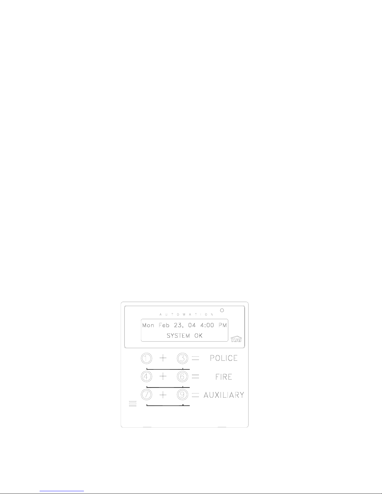
Emergency Keys
Emergency alarm conditions can be activated through the console. These conditions (Fire, Poli ce, and Auxiliary) are initiated
with the simultaneous depression of two keys for approximately 1-second.
OMNI
NOTE: The Emergency keys are always armed. The Fire and Auxiliary emergency alarms are silenced by pressing the ' * ' key.
To cancel a Police emergency alarm you must press the Off key and enter your code.
POL
FIRE
AUX
Page 10

Police Emergency
When the 1 key and the 3 keys are pressed simultaneously, the Police Emergency alarm is activated. This alarm operates exactly
the same as described for Burglar Alarm Activated except:
• The console display indicates: "BURGLARY! - POLICE EMERG TRIPPED".
• The interior sounder and the outdoor siren are activated immediately. There is no outside siren delay.
Fire Emergency
When the 4 key and the 6 key is pressed simultaneously, the Fire Emergency alarm is activated. This alarm operates exactly the
same as described for Police Emergency Button except:
• The sounders activates in a 3 pulse temporal pattern distinguish the fire alarm from the burglar alarm.
• The console display will read: "FIRE ALM - FIRE EMERG TRIPPED".
The Fire Emergency alarm can be turned off at any time by pressing the ' * ' key.
Auxiliary Emergency
When the 7 key and the 9 key is pressed simultaneously, the Auxiliary Emergency alarm is activated.
• The console beeper comes on - display indicates: "AUX ALARM! AUX EMG BTN TRIPPED".
• The console beeper continues to sound until the alarm is reset.
Duress Code Entered or Duress Alarm Activated
(See Duress Code for a description of when to use)
In the event that you enter your duress code or a Duress zone is tripped, the system performs a silent dial out as follows:
• No alarms, lights or console beepers are activated. The system does not display the duress alarm.
• The system waits the dial out delay, then begins to dial out.
If you are having your system monitored, the central station will be sent a code representing a silent alarm (duress).
Alarm Reset
The alarm system will reset itself after the outside siren has been on for 1-30 minutes. When the alarm system resets, any zone
that is ready is reactivated, so the alarm system will be activated again if the zone is tripped. If a zone remains not ready (i.e. a
door has been left open) it will be automatically bypassed when the alarm resets.
Alarm Cancel
At any time, you can silence your alarm system by pressing the Off key and entering your code. If the system has reported, or is
in the process of reporting an alarm to a central station, it will send the alarm code followed by a code indicating that the user has
canceled the alarm. If an alarm is canceled before the dial out delay has expired, the system will not report any alarm.
If an alarm is canceled during a voice dial out, the system hangs up immediately.
Page 11

Trouble Indications
The Omni IIe constantly monitors the alarm zones and several internal matters and will alert you if it detects trouble. The
particular trouble is indicated on the bottom line of the display and a trouble signal is given by beeping the console beeper
continuously, 2 beeps per second.
When any trouble condition occurs, the console will beep twice p er second and continue to beep until the ' * ' key (cancel) is
pressed to acknowledge the trouble. The console will say "TRBL NOW" (trouble now) if the trouble condition actually exists
while you are looking at the console. It will say "HAD TRBL" (had trouble) if the trouble occurred and then corrected itself.
The following are trouble indications and their meanings:
¾ ZONE NAME TRBL NOW or HAD TRBL: If the reading for a zone becomes abnormal, trouble will be indicated on that
zone -See Status \ Test. Excessive resistance in the contact and wiring usually causes trouble on security zones. If the cause
is not obvious, call your installer for service.
¾ AC POWER OFF TRBL NOW or HAD TRBL: Indicated if the normal house current powering the Omni IIe controller is
interrupted for more than 3 minutes. If this happens without good cause, check the wall mounted transformer to ensure that it
hasn't come out of the wall socket and check to see that the socket has power.
¾ BATTERY LOW TRBL NOW or HAD TRBL: Every hour, the Omni IIe takes a dynamic test of the battery. If the battery
voltage is too low, then the console will indicate "BATTERY LOW". If this happens, make sure that the battery is
connected. The "BATTERY LOW" indication will remain until the next battery test is executed, 1 hour later, or when a
Status | Test command is given.
¾ COMMUNICATOR TRBL NOW or HAD TRBL: Indicated if the digital communicator (not the voice dialer) was unable
to make contact with the Central Station after trying both numbers multiple times. If this happens, there cou ld be a problem
with the system, central station, or the phone line. Call your installer for service.
¾ FUSE TRBL NOW or HAD TRBL: Indicated when the solid state fuse that protects the "Auxiliary" power supply opens.
The fuse will automatically reset when the fault condition is cleared.
¾ PHONE LINE DEAD TRBL NOW or HAD TRBL: Indicated if the phone line is dead for more than 1 minute.
To silence the trouble beeps on the console, press the ' * ' key. If more than one type of trouble has occurred, the display will
show each one for two seconds. Pressing the ' * ' key will acknowledge all trouble indications.
If the trouble condition occurs again, the conso le beeper will beep again - See Set Up Arming, Beep On Trouble if you wish to
disable the beeper.
¾ NO CONTROLLER DATA: Indicated when console's alarm functions are no longer operational. This may indicate a
wiring problem to the console or a more serious problem. Call your installer for service.
Codes
There are 16 user codes that you may assign to users of the system. All Omni IIe codes are 4 digits in length. A code can be any
number from 0001 to 9999. Each user should be assigned a security code with an authority level, areas that can be accessed (if
area arming is used), and times and days in which the code will be valid . Memorize your code s! Don't give them to anyone who
doesn't need to know them.
The levels of authority that you can assign to a user code are Master, Manager, and User.
Master Code
The Master code allows complete access to the entire system. Only the owner(s) or the one(s) who will govern the system should
have and use the master code. A Master code is allowed access to all areas, all the time.
User code 1 is always set to a Master code - See Set Up Codes.
Page 12

Manager Code
The Manager codes can arm/disarm the security system in assigned areas, during assigned times. The Manager code can access
functions that are code protected in High Security mode. Managers may also access the system from an outside telephone line.
User Code
User codes can only be used to arm and disarm the security system in assigned areas when the time assigned to that code is valid.
Duress Code
If you are forced to disarm the system against your will by an intruder, disarm it as you normally would, but use the Duress Code
instead of your normal code. The system will disarm normally. No sirens will sound, no lights will flash, but the Omni IIe will
perform a silent dial out and say that this is a silent alarm.
To stop a silent dial out, turn your security system off the usual way, pressing Off key, then your code.
Panic Switches
If you have had panic switches installed, they are always armed. Pressing a panic switch will cause the alarm to activate. This
alarm can only be silenced by pressing the Off key and a valid code on the console.
Area Arming
If your installer has enabled the Area feature, the security system may be armed in Area 1, and disarmed in Area 2. In fact, each
area may be armed in different security modes at the same time. Each area will have its own console that will control that area
independently from the other.
When disarming the security system or arming the security system in any mode, the system will automatically control all security
functions in the area of that console if your code is valid for that area.
If you have a Master code, your code is valid in any area. If you are in Area 2, and wanted to arm the system in the Away mode,
simply press the Away key and enter your code. The system will automatically arm Area 2. The security mode in Area 1 will not
change.
If you have a code that is only valid in Area 1, you will not be able to disarm or arm Area 2.
If you are in Area 1 and wish to disarm the security system in Area 2, Omni IIe will allow you to disarm Area 2 from the console
in Area 1 if you have a Master code or a code that is valid for both areas.
From the top-level display or from the main menu, press the 2 (SEC) key on the console keypad.
Press the 0 (OFF) key, the display will show:
DISARM
ENTER CODE: #=AREA
Press the ' # ' (AREA) key, the display will show:
AREA:
ENTER AREA 0=ALL
The Area number can be entered followed by the ' # ' key, or the arrow keys may be used to scroll through a list of areas. If the
' 0 ' key is pressed, then all areas will be selected.
Press the 2 key then the ' # ' key. You will then be prompted to enter your code. The display will show:
DISARM AREA 2
ENTER CODE:
↓
Page 13

If the ' 0 ' (ALL) key had been selected, the display will show:
DISARM ALL AREAS
ENTER CODE: #=AREA
As the four-digit code is entered, "X" characters are echoed after the "ENTER CODE:" prompt.
If the Master code or a valid code is entered, the console will beep one time and Area 2 will be disarmed.
Even if Auto Bypass is enabled, the system will not arm another area if any zones in that area are not ready. If any zone in Area 2
is not ready (open), after you enter the code, the console will beep three times and display "AREA 2" on the top line, and "ZONE
NOT READY" on the bottom line.
AREA 2
ZONE NOT READY #=RETRY
In order to arm Area 2 from a console in Area 1, you must first secure or Bypass any zones in AREA 2 that are "Not Ready".
Press the ' # ' key to retry the arming process.
To Bypass or Restore a zone in Area 2 from a console in Area 1, or viceversa, it is first necessary to "go to" that area.
GOTO Area
From the security menu, press the # (GOTO) key on the console keypad.
AREA:
ENTER AREA
The Area number can be entered followed by the ' # ' key, or use the arrow keys to scroll through a list of areas. Once the area is
selected, you are prompted to enter your code:
GOTO AREA 2
ENTER CODE
The console (AREA 1) will now be temporarily assigned to the selected area (AREA 2) if a valid code for that area (AREA 2) is
entered. All security and control commands will now operate on the selected area (AREA 2), just as if you were physically at a
console assigned to that area (AREA 2). All status displays will show the status of the selected area.
The top line of the display will show the name and security mode for that area.
Use the "go to" function again to return to the area normally assigned to that console (AREA 1). The console will au tomatically
return to its normal area after three minutes of inactivity at the console.
↓
Page 14

Testing Your System
HAI recommends testing your system on a weekly basis to ensure that you are fully protected.
1. Notify your Central Station that you intend to test the system. To test the siren, press the 1 and 3 keys simultaneously.
Press OFF and enter your Code to cancel the alarm and silence the siren.
2. To test the security zones, you will need a partner to walk around your home and open and close all doors, windows, etc.
that are connected to the system while you watch the console. Have a partner open each door and window, then close it.
The display should show the zone name as being "NOT RDY" and then return to "SYSTEM OK" when closed.
3. Have your partner walk in front of all motion detectors (if installed) and verify that the console responds in a similar fashion.
4. Test your smoke detectors as recommended by the manufacturer. Be ready to silence the alarm system as soon as it sounds.
5. From the top-level display or from the main menu, press the 6 key then the 4 key.
- The Battery reading should be over 200 - See Status \ Test.
6. Pick up an inside phone and press the # key. When the menu is spoken, press 8, Then 3. The Omni IIe should say
"ADDRESS IS: "and play your name and address. If it does, the telephone dialer, telephone access and telephone control
systems are all working correctly.
7. If you wish to test your system's link to your Central Station monitoring service, call them first and info rm them that you
will be testing your alarm system. Set off the alarm, allowing sufficient time for any dial out delays that you may have, then
turn the alarm system Off. The Central Station should receive the alarm code.
8. Remember to inform your Central Station when the test is complete.
Page 15

CONTROL
Control Commands
The control features of the Omni IIe make it easy and convenient to control almost any light or appliance from the console or over
the telephone. You may also have your heating and air conditioning (HVAC) under control of the system, which will allow you
to save energy dollars by setting the temperature appropriately when you are home, asleep, or away.
Furthermore, the Omni IIe can be used to program lights to make the home or business look occupied as a deterrent to thieves.
The methods that the Omni IIe uses to control different devices are:
• UPB switches, modules, and keypads for lights and appliances
• CentraLite loads and relays on a LiteJet and Elegance lighting system
• RadioRA switches and dimmers on a Lutron RadioRA lighting system
• ALC switch modules for lights and appliances
• X-10 compatible modules (X-10, X-10 Pro, Leviton, PCS, ACT, Lightolier, etc.) for lights and small appliances.
• HAI Communicating Thermostats for controlling Heating, Ventilation, and Air Conditioning Systems.
• Programmable Energy Saver Modules (PESM) for central heating and air conditioning systems.
• Direct Output Control for relays to activate sprinklers, lighting, electric heating, etc.
An Omni IIe will control:
¾ 64 UPB switches, modules, and keypads (up to 8 rooms of HLC Lighting)
¾ 64 CentraLite loads and relays
¾ 64 RadioRA switches and dimmers
¾ 62 ALC switch modules
¾ 64 X-10 compatibl e modules (four house codes)
¾ 4 HAI Communicati ng Thermostats
¾ 8 PESMs or Voltage Outputs
Omni IIe also has 56 internal "flags" that are used for programming conditionals and executing programs.
About UPB
UPB is a powerline communications standard for lighting and home co ntrol. UPB is a robust, two-way digital powerline carrier
communications protocol which transmits signals over the existing wires in a home. UPB can coexist peacefully with X-10
systems, intercoms, baby monitors, speakers, etc. that communicate over the powerline.
Using a Powerline Interface Module (PIM), Omni IIe sends UPB commands over the existing electrical wiring to special
switches, modules, and keypad controllers (UPB devices) that are designed with UPB technology. UPB switches are two-way
devices, so Omni IIe knows the actual status of the switch when it is controlled locally. In addition, UPB switches, modules, and
keypads can be used to trigger macros in the Omni IIe controller.
Page 16

When set to UPB, the Omni IIe controller can:
¾ Send commands (on, off, bright, dim and level) to individual switches and modules
¾ Receive commands and status from individual switches and modules
¾ Send commands to keypad controllers to change scenes and control LED backlight behind the keys
¾ Receive commands when buttons are pressed on keypad controllers to activate controller macros
¾ Send Link commands to switches, modules, and keypad controllers to activate scenes
¾ Receive Link commands when a button is pressed on a switch or on a keypad controller to activate controller macros
¾ Send “Status Request” messages to switches to update their status in the controller
¾ Receive the UPB Acknowledgement pulse that indicates that a switch has properly executed a command
HAI Lighting Control (HLC) Format
HAI Lighting Control (HLC) combines HAI UPB™ Wall Switches, Dimmers, and Modules, HAI UPB™ Room Controllers, and
HAI UPB™ House Controllers to create lighting scenes that set the proper mood and ambiance for various activities.
HLC format is a defined structure for configuring, programming , and operating all the HLC lighting devices in your home. Each
“House Code” that is configured to use the HLC format consists of 2 rooms with up to 8 HLC devices in each room. Omni IIe
supports up to 8 rooms of HLC lighting. Om ni IIe can contr ol up t o 64 HLC devi ces .
HAI manufactured UPB™ devices (collectively referred to as HLC devices) can be configured using an Omni console or
OmniTouch touchscreen connected to the Omni IIe controller. Other UPB™ devices may be used in the HLC structure, but
cannot be configured using the Omni IIe controller; they must be configured using a PC running the UPB™ UPStart
configuration software – see Configuring HLC Devices.
About Rooms
Each “room” of HLC lighting consists of 8 consecutive unit numbers, starting at Unit 1 (i.e. Room 1 = Units 1-8, Room 2 = Units
9-16, Room 3 = Units 17-24, etc.). Each room can consist of a maximum of 8 HLC devices, configured as follows:
¾ Up to 7 HAI UPB™ Wall Switches, Dimmers, and/or Modules (for controlling up to 7 lighting loads in a room or area)
¾ 1 or more Room Controllers (set a scene in a room, turn the room on and off, and dim and brighten the room)
¾ 1 House Controller (for controlling up to 8 rooms of HLC lighting)
¾ 1 or more House Controllers (used as a general purpose 8 button keypad controllers)
The first unit number in each room (i.e. 1, 9, 17, 25, etc.) is reserved for controlling the room. The name for this unit should
reflect the room name (e.g. Kitchen, Great Room, Theater, etc.) HLC Wall Switches, Dimmers, or Modules cannot be
programmed to these unit numbers. If one or more Room Controllers are used, the first Room Controller should be set to the first
unit number in the group (i.e. Unit 1); additional Room Controllers can be used by setting each to any other unused unit number
in the group (i.e. Units 2-8).
About Room Controllers
The HAI UPB™ 6-Button Room Controller allows for lighting control of a room where HAI UPB™ Wall Switches, Dimmers,
and Modules have been installed. From a Room Controller the room can be turned off (all loads in the group are turned off),
turned on (all loads in the group are turned on), brightened (all loads are b rightened from their current level), dimmed (all loads
are dimmed from their current level), or set to one of 4 lighting scenes (A-D).
Room Controller LED Indicators
When the room is turned on, the LED indicator behind the “On ” button is illuminated and all others are turned off. When the
room is turned off, the LED indicator behind the “Off” button is illuminated and all others are turned off. When the room is
brightened, the LED indicator behind the “On” is illu minated and all others are turned off. When th e room is dimmed, the LED
indicator that is currently illuminated stays on. When the room is set to a lighting scene (A-D), the LED indicator behind the
respective scene letter is illuminated and all others are turned off.
When “Status Tracking” is enabled (this is the default setting), Omni IIe keeps track of the exact status of each unit even when a
lighting scene is initiated by the Room Controller. Room Controllers also keep track of when individual switches in a room are
turned on and off. When all of the lighting loads in a room are turned off, the “Off” indicator is illuminated. If any of the lighting
loads in a room are turned on at an HAI UPB™ Wall Switch or Dimmer, the “On” indicator will illuminate and the “Off”
Page 17

indicator is turned off. Likewise, if the “On” indicator or one of the scene indicators is illuminated, and then all of th e lighting
loads are turned off at HAI UPB™ Wall Switches and/or Dimmers, the “Off” indicator will illuminate and any others are turned
off.
About House Controllers
The HAI UPB™ 8-Button House Controller allows for controlling all 8 rooms of lighting where HAI UPB™ Wall Switches,
Dimmers, and Modules have been installed. It can also be configured as a general purpose 8 button keypad controller used to
trigger 8 different macro programs in the Omni IIe controller or to toggle between two different actions (i.e. turn lighting load
on...turn lighting load off) each time a pushbutton is pressed.
When used to control rooms of lighting in the HLC structure, each button on the House Controller is used to toggle all of the
lights in the respective room on and off. When the room is turned on, the LED indicator behind the respective button is
illuminated and all of the lights in the room are turned on. When the room is turned off, the LED indicator behind the respective
button is turned off and all of the lights in the room are turned off. If a lighting load in the respective room is turned on, th e LED
indicator behind the button is illuminated. When all lighting loads in the respective room are turned off, the LED indicator behind
the button is turned off.
When used to control rooms of lighting in the HLC structure, each House Controller controls 8 consecutive rooms (i.e. Room 1-
8). To configure a House Controller to control a group of 8 rooms, it must be set to the last unit number in one of the respective
rooms. For example, a House Controller set to Unit 8, 16, 24, 32, 40, 48, 56, or 64 is configured to control rooms 1-8. This
allows you to have up to 8 House Controllers throughout the house that control rooms 1-8.
Within the HLC structure, House Controllers can also be configured as a general purpose 8 button keypad controller that is used
to trigger 8 different macro programs in the Omni IIe. When configuring a House Controller as a general purpose 8 button
keypad controller, it must be set to a unit number between the first and last unit number in a room (i.e. 2-7, 10-15, 18-23, 26-31,
34-39, etc.). When configured as a general purpose 8 button keypad controller, programs must be created in the Omni IIe
controller for the LED indicator behind each button to function.
About CentraLite
CentraLite is a centralized lighting control system that uses hardwired ligh ting control technology to co ntrol lighting loads, fans,
and mechanical low voltage relays.
CentraLite lighting scenes are used to control groups of lights which are preset to turn on to various levels of dimming.
When set to CentraLite, the Omni IIe controller can:
¾ Send commands (on, off, and level) to individual loads and relays
¾ Receive status (on and off) from individual loads and relays
¾ Execute scene commands (on and off) to control of up to 255 CentraLite lighting scenes
¾ Receive commands when buttons are pressed on a CentraLite keypad (up to 127)
About Lutron RadioRA
Lutron RadioRA uses wireless communication technology to control lighting. Each Switch or Dimmer controls one Zone, or area,
of lighting in a RadioRA system. Accessory Switches and Dimmers are used to control the lights locally from up to 9 additional
locations. Master controls provide control and monitoring for all the lights in a Rad ioRA system.
Phantom Buttons are “virtual” buttons in the RS232 Interface. Though there are no physical buttons that represent these Phantom
Buttons, they work very similarly to buttons on RadioRA Master Controls. Phantom Buttons are intended to give the RS232
Interface control over multiple RadioRA Switches and Dimmers with one command. To control more than one device at one time,
Phantom Buttons are recommended.
A Zone is any individual RadioRA Switch or Dimmer. A RadioRA System has a maximum of 32 Lighting Zones. Zone Numbers
can be used to identify any individual Zone (one Switch or one Dimmer), in a RadioRA system via the RS232 Interface. The
Chronos System Bridge and Timeclock bridges two RadioRA systems for a total of 64 Lighting Zone Controls and 24 Master
Controls.
Page 18

When set to RadioRA, the Omni IIe controller can:
¾ Send commands (on, off, and level) to individual Switches and Dimmers
¾ Receive status (on and off) from individual Switches and Dimmers
¾ Receive commands when buttons are pressed on Master Controls
¾ Execute Phantom Button commands
About ALC
ALC is intended for installation in homes, which have been pre-wired for installation of ALC system products. Omni IIe controls
lights and appliances by sending commands over the ALC signal wiring to ALC Switch Modules. ALC Switches communicate
with the Omni IIe over low voltage signal wire. They are two-way devices, so the controller always knows the actual status of the
switch. In addition, ALC switches can be used to set scenes by triggering macros in Omni IIe.
When ALC Lighting Control Modules are being used, it is also possible to "ramp" the lighting level of an ALC Dimmer Switch to
a new level at a controllable ramp rate.
ALC Module Types
The ALC modules types are: Dimmer Switch, Relay Switch, Slave Switch, Program Switch, and 4-Button Scene S wit c h M odule s.
About X-10
The Omni IIe controls lights and appliances by sending commands over your existing electrical wiring to special switches,
outlets, receptacles, and modules, collectively referred to as X-10. Each module (or group of modules) is assigned a House Code
and a Unit Number so that the Omni IIe can control the modules individually. When a module hears a command from the Omni
IIe for its house code and unit number, it executes the command.
There are 3 different X-10 formats: Standard X-10 (Preset Dim), Extended X-10 (Extended Level), and Compose.
Any module that is "X-10 Compatible" will work with the Omni IIe. The modules come in various types.
House Codes
Omni IIe can control up to 64 lighting and appliance devices. Each device (switches, modules, and keypad) has its own Unit
Number (1-64). Omni IIe groups devices by “House Code”, which consists of 16 consecutive unit numbers, starting at Unit 1.
Each “House Code” can be configured to a different lighting protocol format such as: Standard X-10, Extended X-10, Lightolier
Compose, UPB (open UPB format where you can use the programming capability in the Omni IIe controller to communicate with
the UPB network), Lutron RadioRA, CentraLite, or HAI Lighting Control (HLC).
Different lighting devices can not share the same House Code. However, different lighting devices can coexist on an Omni IIe
system as long as they are on separate House Codes. For example:
House Code 1 (Units 1-16) = HLC
House Code 2 (Units 17-32) = UPB
House Code 3 (Units 33-48) = X-10 Extended
House Code 4 (Units 49-64) = CentraLite
Page 19

Unit Numbers
Omni IIe systems have 128 total Unit Numbers. They consist of HLC, UPB, CentraLite, RadioRA, ALC, Compose, and X-10
module unit numbers, hardwire voltage output unit numbers, and internal flag unit numbers as follows:
Omni IIe Unit Numbers Module / Output Unit Numbers
1 - 16
17 - 32
HLC Room 1 and 2, UPB Unit ID 1-16, CentraLite loads 1-16, RadioRA Lighting Zones and
Master Controls 1-16, or X-10 modules 1 – 16 (House Code X)
HLC Room 3 and 4, UPB Unit ID 17-32, CentraLite loads 17-32, RadioRA Lighting Zones
and Master Controls 17-32, or X-10 modules 1 – 16 (House Code X+1)
(1 - 31) ALC addresses 1-31, Branch 1 *
33 - 48 HLC Room 5 and 6, UPB Unit ID 33-48, CentraLite loads 33-48, RadioRA Lighting Zones
and Master Controls 33-48, or X-10 modules 1 – 16 (House Code X+2)
49 - 64 HLC Room 7 and 8, UPB Unit ID 49-64, CentraLite loads 49-64, RadioRA Lighting Zones
and Master Controls 49-64, or X-10 modules 1 – 16 (House Code X+3)
(33 – 63) ALC addresses 1-31, Branch 2 *
65 - 72 Voltage Outputs (1-8), Fully Configurable
79 – 128 Internal Flags
“X” Represents the House Code setting on the Omni IIe Controller
“*” If used
Scrolling Through Names
The Omni IIe stores names for Units, Zones, Buttons, Codes, Temperatures, and Messages so that you don't have to remember
that "UNIT 5" is the "DEN LIGHT" and "ZONE 1" is the "FRONT DOOR". In general, any time you enter a unit, zone, button,
code, temperature, or message number, you can press the down arrow key to display its name, then use the up and down arrow
keys to scroll through the list of other names. This is true when entering commands and programming on the console. Only
named items are displayed on an OmniTouch touchscreen.
Controlling Units
The control menu is used when controlling lights and appliances. To enter the control menu, from the top-level disp lay or from
the main menu, press the 1 (CTRL) key on the console keypad. Omni IIe will automatically display the first n amed item in that
list. The down arrow key can then be used to scroll through the list, and the ' # ' key is used to select the item. If the specific item
number is known, enter the item number followed be the ' # ' key, or scroll up and down among the named items.
After the unit has been selected, press the ' # ' key. The console will display:
Controlling a Room of HLC Lighting
Living Room
0=OFF 1=ON 2-5=A-D
Living Room
6=SET #=STA
¾ Press 0 (OFF) to turn the selected room off (all lighting loads in the room are turned off).
↓
↑
¾ Press 1 (ON) to turn the selected room on (all lighting loads in the room are turned on).
¾ Press 2 (A) to set all of the lighting loads in the selected room to their preset levels for Scene A.
¾ Press 3 (B) to set all of the lighting loads in the selected room to their preset levels for Scene B.
¾ Press 4 (C) to set all of the lighting loads in the selected room to their preset levels for Scene C.
¾ Press 5 (D) to set all of the lighting loads in the selected room to their preset levels for Scene D.
¾ Press 6 (SET) to set up a lighting scene for the all of the lighting loads in the selected room (On, A-D).
¾ Press # (STA) to view the current status of the room.
Page 20

Configuring Lighting Scenes in an HLC Room
Lighting scenes are created by configuring light levels for HLC lighting devices in a room. Each HLC device in a room can store
up to four different preset lighting scenes (Scenes A-D) and one “On” Scene (preset lighting levels for each device when the room
is turned on). To set a lighting scene using the Omni console, adjust all of the HLC devices in the room to the desired lighting
levels. The desired lighting levels (0% - 100%) may be set manually at the switch, or by issuing commands from the Omni IIe
controller. After the desired lighting levels are set, use the 6 (SET) command to save the new “light levels” for each device in the
selected room.
Living Room SET
1=ON 2-5=A-D
When the scene command is transmitted (either using a Room Controller or by the Omni IIe controller), each HLC device in the
specified room will brighten or fade to its preset level for the selected scene.
Each lighting scene can also be set or easily changed using the pushbuttons on the HAI UPB™ 6-Button Room Controller, as
follows:
Step Operation
1 Press the desired pushbutton on the HAI UPB™ 6-Button Room Controller to activate the current scene (preset lighting
level) in each of the HLC devices.
2 Use the local Decora-style rocker switch on each UPB™ Wall Switch Dimmer(s) to set the desired lighting level(s) or
issue commands from the Omni IIe controller.
3 Press the pushbutton on the HAI UPB™ 6-Button Room Controller five (5) ti mes quickly.
4 Each UPB™ Wall Switch Dimmer will flash its lighting load one time to indicate that the new level has been
configured.
Controlling Individual Lighting Loads in an HLC Room or UPB Units
To control individual lighting loads in a room, use the down arrow key to scroll through the list of units. When the unit is
displayed, press the ' # ' key. For HLC/UPB lighting loads, the console will display:
LR Sconce
0=OFF 1=ON 2=DIM 3=BRT
LR Sconce
4=LVL 6=LED 9=TIM #=STA
¾ Press 0 (OFF) to turn the selected lighting load off .
↓
↑
¾ Press 1 (ON) to turn the selected lighting load on.
¾ Press 2 (DIM) to dim the selected unit (1-9 steps, each step is 10% from its current level).
¾ Press 3 (BRT) to brighten the selected unit (1-9 steps, each step is 10% from its current level).
¾ Press 4 (LVL) to set the desired lighting level of the selected unit (0%-100%).
¾ Press 6 (LED) to turn on or off the LED behind the specified button o n a general p urpo se 8-Button or 6-Button Keypad.
• Specify 1-8 to control the LED behind buttons 1-8 respectively, and then select 0 (OFF) or 1 (ON).
¾ Press 9 (TIM) to time the selected unit (On, Off, Dim, Brighten).
• Timed commands may be from 1-99 seconds, 1-99 minutes or 1-18 hours.
¾ Press # (STA) to see the exact status of a UPB device. When the ' # ' key is pressed, Omni IIe sends a “Status Request”
message to the selected device for its current state. The exact state is then displayed.
LR Sconce
STATUS 67%
Note: When a UPB signal is received over the powerline, Omni IIe will automatically update the status of the device.
Controlling CentraLite Units
Page 21

Entry Lights
0=OFF 1=ON 2=DIM 3=BRT
↓
Entry Lights
4=LVL 5=RMP 9=TIM #=STA↑
¾ Press 0 (OFF) to turn the selected unit off.
¾ Press 1 (ON) to turn the selected unit on.
¾ 2 (DIM) does not affect CentraLite units.
¾ 3 (BRT) does not affect CentraLite units.
¾ Press 4 (LVL) to set the desired lighting level of the selected unit (0%-100%).
¾ 5 (RMP) does not affect CentraLite units.
¾ Press 9 (TIM) to time the selected unit (On or Off). Timed commands may be from 1-99 seconds, 1-99 minutes or 1-18
hours.
¾ Press # (STA) to see the status (On or Off) of a CentraLite device.
Controlling RadioRA Units
Entry Lights
0=OFF 1=ON 2=DIM 3=BRT
↓
Entry Lights
4=LVL 5=RMP 9=TIM #=STA
↑
¾ Press 0 (OFF) to turn the selected unit off
¾ Press 1 (ON) to turn the selected unit on.
¾ 2 (DIM) does not affect RadioRA units.
¾ 3 (BRT) does not affect RadioRA units.
¾ Press 4 (LVL) to set the desired lighting level of the selected unit (0%-100%).
¾ 5 (RMP) does not affect RadioRA units.
¾ Press 9 (TIM) to time the selected unit (On or Off). Timed commands may be from 1-99 seconds, 1-99 minutes or 1-18
hours.
¾ Press # (STA) to see the status (On or Off) of a RadioRA device.
Note: When a RadioRA device transmits a signal (i.e. Switch or Dimmer is turned on or off locally, Mater Control button is
pressed, or Phantom Button is executed), Omni IIe will automatically update the status of each affected device.
Controlling ALC or X-10 Units
Entry Lights
0=OFF 1=ON 2=DIM 3=BRT
↓
Entry Lights
4=LVL 5=RMP 9=TIM #=STA
↑
Page 22
 Loading...