

Page 1
62A12-1
Hi-Fi Expansion Kit
Installation Manual
Document Number 62I12-1 Rev A
October, 2006
Page 2

Copyright © 2006 Home Automation, Inc.
All Rights Reserved
Page 3

Description
This kit expands the HAI Hi-Fi Whole Home Audio Distribution System from 4 Zones and 4 Sources to
a full 8 Zone, 6 Source system.
Features:
• Adds an additional 4 zones of audio and 2 audio sources throughout your home
• Modular Zone Amplifier Cards plug into the Hi-Fi Main Board Assembly
• Remote Input Modules (RIM) and Volume-Source Control (VSC) Units connect using Standard
Category 5 Wiring
Includes:
• 4 Zone Amplifier Cards
• 2 Remote Input Modules (RIM) with 2 IR Flashers
• 4 Volume and Source-Control (VSC) Units
• Power Supply that powers 4 zone amplifiers
• Manual
Installing Remote Input Modules (RIM)
All audio sources are connected directly to Remote Input Modules (RIM) in rooms that will have music
sources. Remote Input Modules connect directly to the Hi-Fi Main Assembly using Cat 5, unshielded,
twisted pair (UTP) for communications. Each end of the wire is terminated with an RJ45 connector.
The correct wiring scheme for the Cat 5 cable is standard EIA/TIA 568A. Properly terminating the
Cat 5 cable is crucial for the operation of the system.
It is best that no single run of Cat 5 exceeds 500 feet.
Insert the RJ45 connector on one end of the cable to the respective source input jack (1-6) under
“Remote Audio In / IR Out” on the Hi-Fi Main Assembly. Insert the RJ45 connector on the other end of
the cable to the jack labeled “Remote Audio” on the RIM.
Changing the Color of the RIM
The color of the RIM may be changed to complement the interior décor. The RIM is supplied with a
white faceplate and insert. Additional colors are available; contact your HAI distributor for more
information. Change the color of the RIM as follows:
Page 1
Page 4
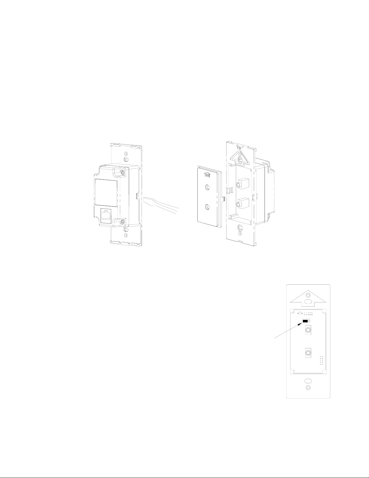
1. Remove the faceplate.
2. The insert attaches to the RIM with one latch on the right and one on the left. Using a small-bladed
screwdriver, gently depress the latch on one side while lifting up on the insert. Once the latches are
released on one side, remove the insert from the other side.
3. Align the latches of the new insert to the openings on the RIM and gently snap into place.
4. Attach the new faceplate.
Setting the Frequency of the IR Output
When using the RIM to send IR data to source equipment, there are
two different IR carrier frequencies in which the RIM can transmit
the IR signal. The default setting of 38 kHz is used for most audio
sources. However, most cable and satellite converter boxes operate
at a higher IR carrier frequency closer to 56 kHz. Each RIM has a
jumper that allows you to change the frequency of the IR output
when using such devices.
To change the frequency setting, remove the faceplate and insert
from the RIM as described under “Changing the Color of the RIM”.
Once The Insert Has Been Removed, Move The Frequency Jumper
(CN1) From The “38khz” Position To The “56khz” Position.
FREQUENCY
JUMPER
TOP
38KHz 56KHz
CN1
Page 2
Page 5

IR Output
Each RIM ships with an IR flasher (62A08-1). The IR flasher is used for sending IR data to the source
equipment. When you point your source equipment remote control at the IR receiver in the VSC and
send a signal, the IR data is routed to the appropriate RIM (to which the source is connected), which
then sends the IR signal through the IR flasher to the source equipment.
IR OUT
AUDIO IN
Hi-Fi RIM
Remote Input Module
RIM
IR RECEIVER
WINDOW
SOURCE EQUIPMENT
IR FLASHER
IR
(FRONT)
Installing Volume-Source Control (VSC) Units
The audio sources can be selected and controlled by any Volume-Source Control (VSC). Additionally,
each VSC include an IR receiver that allows you to remotely control the Hi-Fi system and/or audio
sources from any zone in the house. Volume-Source Control (VSC) Units connect directly to the Hi-Fi
Main Assembly using Cat 5, unshielded, twisted pair (UTP) for communications. Each end of the wire
is terminated with an RJ45 connector. The correct wiring scheme for the Cat 5 cable is standard
EIA/TIA 568A. Properly terminating the Cat 5 cable is crucial for the operation of the system.
The total distance of Cat 5 between the Hi-Fi Main Assembly and the VSC units must not exceed
2000 feet. It is best that no single run of Cat 5 exceeds 250 feet.
Insert the RJ45 connector on one end of the cable to zone input jack (1-8) under “Zone Control / IR In”
on the Hi-Fi Main Assembly. Insert the RJ45 connector on the other end of the cable to the jack labeled
“Zone Control” on the VSC.
Page 3
Page 6

Changing the Color of the VSC
The color of the VSC may be changed to complement the interior décor. The VSC is supplied with a
white faceplate, knob, and insert. Additional colors are available; contact your HAI distributor for more
information. Change the color of the RIM as follows:
1. Remove the faceplate. Firmly grasp the knob and pull straight outward until the knob is removed.
2. The insert attaches to the VSC with one latch on the right and one on the left. Using a small-bladed
screwdriver, gently depress the latch on one side while lifting up on the insert. Once the latches are
released on one side, remove the insert from the other side.
3. Align the latches of the new insert to the openings on the RIM and gently snap into place.
4. Insert the new knob onto the volume control shaft. Attach the new faceplate.
Setting the Zone Address
Although the Hi-Fi Main Assemble has separate RJ45 connectors for
each zone, each VSC must be configured to a specific zone address to
establish its location. This setting is made on the back of the VSC using
a rotary switch. To set the zone address, place a small screwdriver in the
slot on the rotary switch and turn it to the appropriate zone address
number 1-8
Page 4
Zone 1-8
Model 62A03-1
Volume Source Control
Zone Control
Page 7

Speaker Wiring
When running the cables for speakers, use 16-gauge two-conductor or four-conductor (four-conductor
stranded is recommended for neater installation) speaker wire. Speaker cable is homerun from the
speaker location to the location of the Hi-Fi Main Assembly.
The Hi-Fi System is designed to work with one pair of speakers per zone.
Terminating Speaker Wires
Always observe proper orientation of the positive and negative signal for each speaker connection.
Typically, when using two-conductor speaker wire, the red wire indicates positive (+) and black wire
indicates negative (-). Another indication of positive is a dark line running through the insulation.
Four-conductor wire can also be used and makes for a neater installation. Four-conductor wire has four
separate wires in one outer jacket, making it possible to run a single speaker wire for a pair of zone
speakers. This type of wire typically uses red and black for one speaker and white as positive and green
as negative for the second speaker.
SPEAKERS SPEAKERS
Use 16 gauge speaker wire (4 conductor
stranded is suggested for neat installation)
Page 5
Page 8

Installing Zone Amplifier Cards
Zone Amplifier Cards (ZAC) can be added at any time to increase the total number of zones to eight.
To install a Zone Amplifier Card:
1) Power down the Hi-Fi system by
unplugging both Power Supply units
(if applicable) from the inputs labeled
“Power” on the Hi-Fi Main Assemble.
2) Pull upward on each of the 4 plungers
until you hear them snap
PLUNGER PLUNGER
3) Remove the cover from the
Hi-Fi Main Assembly by
lifting it away from the
Hi-Fi circuit board.
PLUNGERPLUNGER
Page 6
Page 9

4) Install additional Zone Amplifier Cards in an empty connector (CN5-CN8) by positioning the
Zone Amplifier Card directly over the connector and gently but firmly pushing down on both
sides of the card until the top and bottom are securely seated into the connector.
5) Replace the cover by pushing down on each of the 4 plungers until you hear them snap.
6) Reconnect each Power Supply.
Page 7
Page 10

Powering the Hi-Fi System
The Power Supply (HAI Part Number: 62A07-1) powers the Hi-Fi processor and 4 Zone Amplifier
Cards. One Power Supply is needed to power Zones 1-4 and a second Power Supply (supplied) is used
to power Zones 5-8 (when connected to the Power jack on the right).
1) Insert the connector for the Power Supply into the Power jack marked “PJ1” (jack to the left) under
the section labeled “Power Zones 1-4” on the Hi-Fi Main Assembly.
2) Plug the power cord from the Power Supply into a 120 VAC outlet. The “POWER ON” LED will
illuminate. The Hi-Fi system will start. Follow the instructions in the User’s Guide for operation.
3) Insert the connector for the Power Supply into the Power jack marked “PJ2” (jack to the right) under
the section labeled “Power Zones 5-8” on the Hi-Fi Main Assembly. Plug the power cord from the
Power Supply into a 120 VAC outlet. The “POWER ON” LED will illuminate.
Zones 1-4 Zones 5-8
- +
Power
One 62A07-1 Power Supply is used to power
Zones 1-4. A second 62A07-1 Power Supply
is used to power Zones 5-8.
POWER SUPPLY
HAI Part Number: 62A07-1
Universal Power Su pply for Hi-Fi
For Zones 1-4
(Supplied with 4 Zone, 4 Source Kit)
POWER SUPPLY
HAI Part Number: 62A07-1
Universal Power Supply for Hi-Fi
For Zones 5-8
(Supplied with Hi-Fi Expansion Kit)
Page 8
Page 11

Specifications
Zones 1-8 Power Amplifier Outputs
Continuous Average Output Power: 30W (15W x 2) Two channels driven 30-20kHz @1% THD
Rated Distortion (1/2 power): 0.40%
Rated Impedance: 6 Ohms
Damping Factor: 50+
Frequency Response (20-20kHz): ±2dB
Preamplifier Section
Variable output: 0-600mV
Impedance: 600 Ohms
Source Inputs 1-6
Input Impedance: 10K
Input Sensitivity for rated power: 300mV RMS
Input Overload: 3V RMS
Emitter Outputs
Output Drive Current: 100mA
Output Drive Voltage: 5V
System
System On: 5V @ 50mA (Ring = Ground)
Page / Mute input: Normally open (close to activate)
Power Requirements
Power Supply Input (each): 100-240VAC, 50/60Hz, 120W
Power Supply Output (each): 30VDC, 3 Amps
Power Consumption
All channels driven to full-rated power: 240W
Average operating conditions: 30W
No signal: Less than 10W
Physical Specifications
Unit Size (in enclosure): 13” W x 13” H x 4.5” D
Unit Size (on mounting plate): 13.25” W x 8.5” H x 3.75” D
Unit Weight (in enclosure): 14 lb.
Unit Weight (on mounting plate): 8 lb.
Page 9
Page 12

HAI • New Orleans, LA • U S A
 Loading...