

Page 1
HAI UPB™ Lumina Mode Controller
Installation and Operating Instructions
For the following Model:
38A00-3 HAI UPB™ Lumina Mode Controller
READ THESE INSTRUCTIONS BEFORE INSTALLING DEVICE
This HAI UPB™ Lumina Mode Controller is intended for installation in accordance with the National Electrical Code and local
regulations. It is recommended that a qualified electrician perform this installation. Retain these instructions for reference.
This product is for indoor use only. Connect only copper or copper clad wire to this device.
Important Notes Prior To Installation
Be sure that all power to the load has been disconnected by turning off the circuit breaker. Installing an HAI UPB™ Lumina Mode
Controller with power on may expose you to dangerous voltage and may damage the device.
HAI UPB™ Lumina Mode Controller Overview
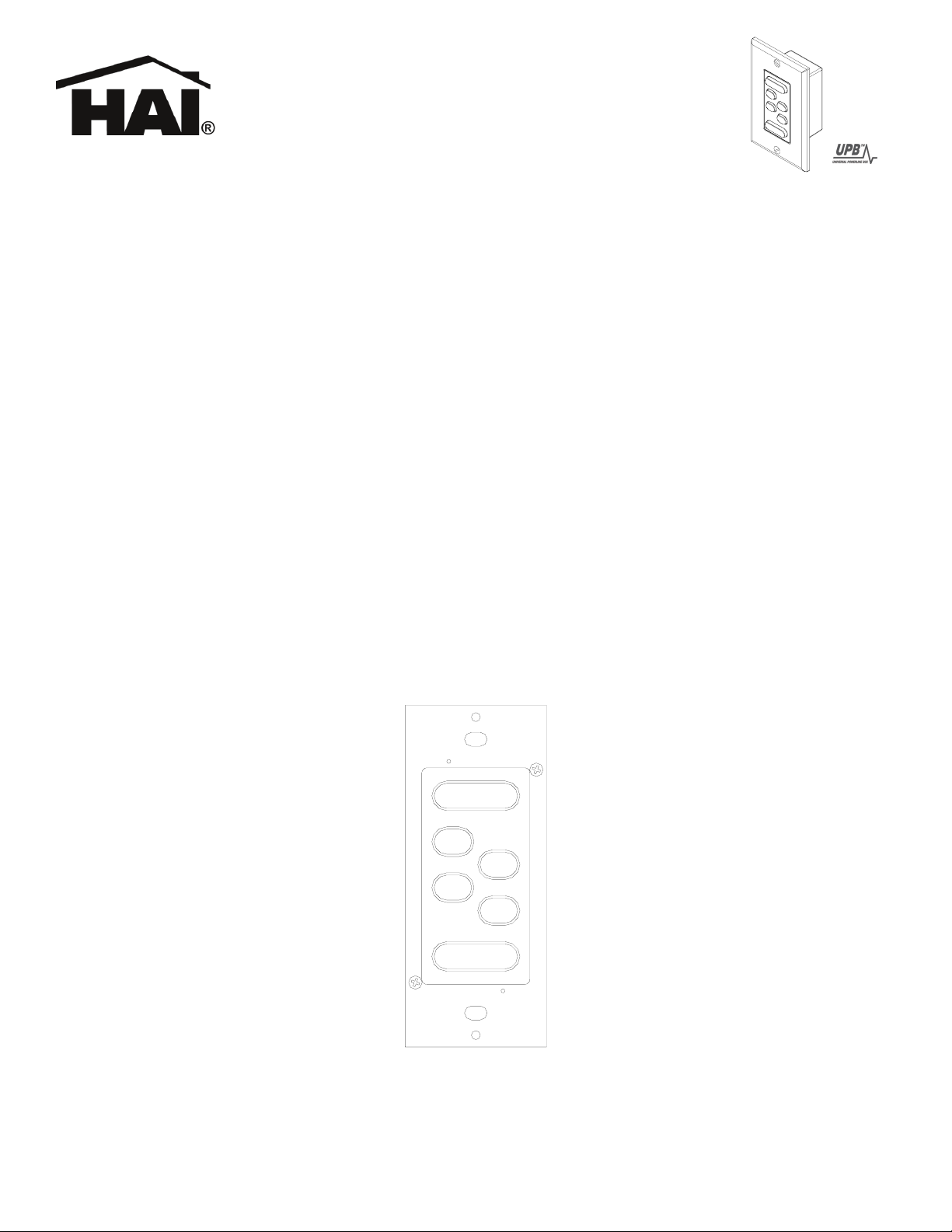
The HAI UPB™ Lumina Mode Controller (Figure 1) is used to easily change the mode before leaving your house, going to bed,
arriving home, going on vacation, entertaining for the evening, or any other special event. It uses the UPB™ two-way powerline
communication technology to communicate with a Lumina controller to initiate programs for preset lights and temperatures.
The HAI UPB™ Lumina Mode Controller has six pushbuttons labeled AWAY, HOME, SLEEP, VAC (Vacation), SPCL (Special),
and PARTY. Each pushbutton is slightly backlit so that the buttons can be seen in a dark room. The pushbuttons of the current
Lumina Mode will be distinctly illuminated, so that you can always tell which mode you are currently in just by glancing at the
Lumina Mode Controller.
To change the current mode from a Lumina Mode Controller, simply press the desired mode button. The new mode button will
illuminate and the lighting and temperatures in your home will be changed accordingly.
AWAY
SLEEP
VAC
SPCL
PARTY
HOME
Figure 1 - HAI UPB™ Lumina Mode Controller
38I00-3, Rev B
Page 2
Changing Switch Color
The color of the HAI UPB™ Lumina Mode Controller may be changed to complement
the interior décor. The HAI UPB™ Lumina Mode Controller is supplied with a white
bezel. Additional colors are available; contact your HAI distributor for more
information. When changing the bezel, make sure that the HAI UPB™ Lumina Mode
Controller is disconnected from all power, and proceed as follows:
1. The bezel attaches to the HAI UPB™ Lumina Mode Controller with two small
Philips head screws: one on the upper-right corner and one on the lower-left corner
(Figure 2).
2. Using a small-bladed Philips screwdriver, unscrew each of the two screws.
Remove the bezel from the back housing.
3. Install the new bezel by aligning the mounting holes on the bezel with the
installation pins on the back housing. Secure bezel to back housing with the two
Phillips screws that were removed in Step 1.
Figure 2 – Changing Switch Color
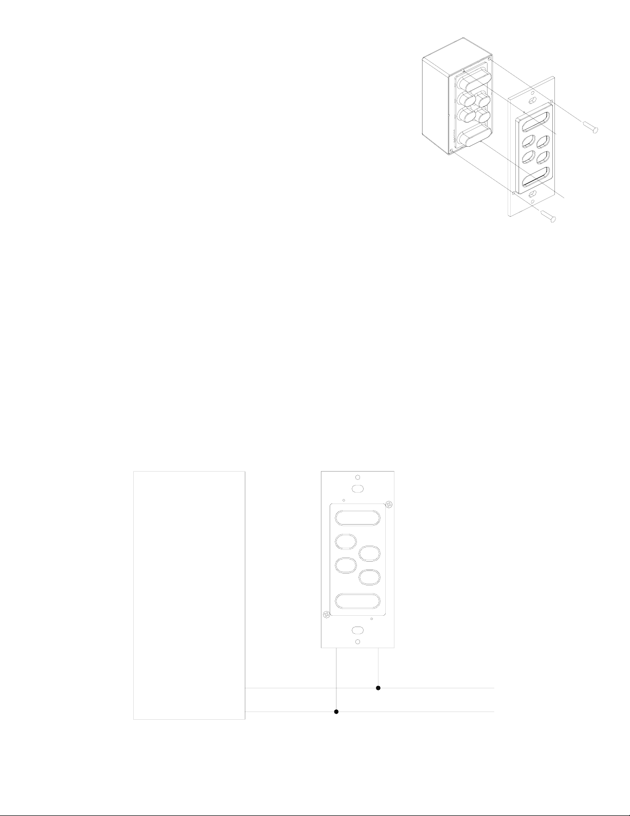
INSTALLATION INSTRUCTIONS
1. Be sure that all power at the wall box has been disconnected by turning off the circuit breaker.
2. If applicable, remove the faceplate from the existing device, remove the existing device from the wall box, and disconnect the
wires from the existing device. Identify the “Line” (black) and "Neutral" (white) wires.
3. Remove ¾” of insulation from each of the wires on the HAI UPB™ Lumina Mode Controller. Install the HAI UPB™ Lumina
Mode Controller by connecting wires per wiring configuration shown in Figure 3.
4. After all connections have been made, be certain that all wire connectors are firmly attached and there is no exposed copper.
5. Gently place the wires and HAI UPB™ Lumina Mode Controller into the wall box with the “AWAY” pushbutton at the top of
device. Using the supplied screws, attach the HAI UPB™ Lumina Mode Controller to the wall box.
6. Before installing the faceplate, restore power to the circuit for testing.
7. After testing the HAI UPB™ Lumina Mode Controller for proper local operation, install a Decora-style faceplate over the HAI
UPB™ Lumina Mode Controller.
MAIN
CIRCUIT
BREAKER
PANEL
120VAC
60Hz
AWAY
SLEEP
VAC
SPCL
PARTY
HOME
BLACK WHITE
Figure 3 – Wiring Diagram
38A00-3
LUMINA
MODE
CONTROLLER
NEUTRAL
LINE
Page 3

HAI UPB™ LUMINA MODE CONTROLLER OPERATION
Although the HAI UPB™ Lumina Mode Controller will perform differently once it is configured by the Lumina controller, the
following describes the operation of the HAI UPB™ Lumina Mode Controller in its factory default configuration.
The HAI UPB™ Lumina Mode Controller has six pushbuttons labeled AWAY, HOME, SLEEP, VAC, SPCL, and PARTY, which
(by factory default) are used to control six lighting scenes. When the pushbutton labeled “AWAY” is pressed, the LED behind the
“AWAY” pushbutton is illuminated and any other is turned off. When the pushbutton labeled “HOME” is pressed, the LED behind
the “HOME” pushbutton is illuminated and any other is turned off. When one of the pushbuttons labeled “SLEEP”, “VAC”, “SPCL”,
or “PARTY” is pressed, the LED behind the respective pushbutton is illuminated and any other is turned off. No more than one
pushbutton is illuminated at a time.
Pushbutton Operation
In its factory default configuration, the “AWAY” pushbutton will brighten the UPB™ Wall Switch Dimmers to 100% at each switch’s
default fade rate when pressed. When the “AWAY” pushbutton is double-tapped, the UPB™ Wall Switch Dimmers will snap to
100%. When pressed or double-tapped, the “AWAY” pushbutton will illuminate and any others are turned off. The “AWAY”
pushbutton is also used to brighten the last lighting scene that was turned on. When the “AWAY” pushbutton is pressed and held
down, the UPB™ Wall Switch Dimmers will slowly brighten, and then stop brightening when the “AWAY” pushbutton is released.
In its factory default configuration, the “HOME” pushbutton will fade the UPB™ Wall Switch Dimmers to 0% (off) at each switch’s
default fade rate when pressed. When the “HOME” pushbutton is double-tapped, the UPB™ Wall Switch Dimmers will snap to 0%.
When pressed or double-tapped, the “HOME” pushbutton will illuminate and any others are turned off. The “HOME” pushbutton is
also used to dim the last lighting scene that was turned on. When the “HOME” pushbutton is pressed and held down, the UPB™ Wall
Switch Dimmers will slowly dim, and then stop dimming when the “HOME” button is released.
In its factory default configuration, the “SLEEP” pushbutton will brighten the UPB™ Wall Switch Dimmers to 80% at each switch’s
default fade rate when pressed or double-tapped. When pressed, the “SLEEP” pushbutton will illuminate and any others are turned
off.
In its factory default configuration, the “VAC” pushbutton will brighten the UPB™ Wall Switch Dimmers to 60% at each switch’s
default fade rate when pressed or double-tapped. When pressed, the “VAC” pushbutton will illuminate and any others are turned off.
In its factory default configuration, the “SPCL” pushbutton will brighten the UPB™ Wall Switch Dimmers to 40% at each switch’s
default fade rate when pressed or double-tapped. When pressed, the “SPCL” pushbutton will illuminate and any others are turned off.
In its factory default configuration, the “PARTY” pushbutton will brighten the UPB™ Wall Switch Dimmers to 20% at each switch’s
default fade rate when pressed or double-tapped. When pressed, the “PARTY” pushbutton will illuminate and any others are turned
off.
CONFIGURING THE HAI UPB™ LUMINA MODE CONTROLLER
The HAI UPB™ Lumina Mode Controller is designed to set the mode in a Lumina system, but also has several configuration options:
Option Factory Default CONFIGURED AS LUMINA MODE CONTROLLER
“AWAY” Pushbutton On Button / Link 001 Sets the Lumina mode to Away.
“HOME” Pushbutton Off Button / Link 002 Sets the Lumina mode to Home.
“SLEEP”, “VAC”, “SPCL”,
and “PARTY” Pushbutton
“AWAY”, “HOME”, “SLEEP”,
“VAC”, “SPCL”, and
“PARTY” LED Indicators
Scene Activator / Links 003,
004, 005, 006 – respectively
Each LED Indicator is assigned
to its pushbutton’s Link ID
Sets the Lumina mode to Sleep, Vacation, Special, and Party,
respectively.
When the Lumina mode is changed, the LED indicator behind
the respective pushbutton is illuminated and any other is turned
off.
Each LED Indicator is mutually
exclusive (only one LED is on
at a time).
UPB Transmission Attempts 2 No change
UPB ID NID = 255
UID = 080
The Lumina controller configures Network ID (NID), Unit ID
(UID), Network Password, Network Name, Room Name,
Device Name, etc.
LED Brightness High No change.
LED Backlighting Enabled No change.
Page 4

Setup Mode
To configure the HAI UPB™ Lumina Mode Controller using a Lumina keypad, it must be put into Setup Mode as follows:
Step Operation
1 Press and hold the “AWAY” and “HOME” pushbuttons simultaneously for at least 3 seconds.
2 All of the LED indicators will blink to indicate that the HAI UPB™ Lumina Mode Controller is in Setup Mode.
Configuring the HAI UPB™ Lumina Mode Controller from a Lumina Keypad
HAI UPB™ Lumina Mode Controllers reside on the 8th unit in any Room. Configure the HAI UPB™ Lumina Mode Controller on
the 8th unit in a Room as follows:
Step Operation
1 Put the HAI UPB™ Lumina Mode Controller into Setup Mode (as described above).
2 On the Lumina keypad, from the main menu or top-level display, press 6 (STATUS), and then press 1 (CTRL).
3 Enter the Unit Number of the HAI UPB™ Lumina Mode Controller followed by the ' # ' key, and then press ' # # '.
4 The display will provide you with step-by-step configuration status. When complete, the display shows “COMPLETED”.
Reset to Factory Default Settings
To reset the HAI UPB™ Lumina Mode Controller to factory default settings:
Step Operation
1 Press and hold the “AWAY” and “HOME” pushbuttons simultaneously for at least 3 seconds.
2 All of the LED indicators will blink to indicate that the HAI UPB™ Lumina Mode Controller is in Setup Mode.
3 Press and hold the “SLEEP” and “PARTY” pushbuttons simultaneously for at least 3 seconds.
4 The LED indicators will stop blinking and the “SLEEP” and “PARTY” pushbuttons will illuminate to indicate that it has
been reset.
SPECIFICATIONS
Model Number 38A00-3
Number of Backlit Pushbuttons with LED Indicators 6
Connections 18 GA
Dimensions 4.1 x 1.7 x 1.5
Weight 0.25 lb.
Mounting Standard J Box
Input Power 120 ± 12 VAC
Input Frequency 60 ± 3 Hz
Operating Temperature -40 °F to 104 °F
Note: It is normal for this switch to make a slight buzzing sound during operation.
LIMITED WARRANTY
HAI warrants this product against defects in material and workmanship, under normal use and service, for a period of two (2) years from the date of
purchase. During the warranty period, HAI will repair or replace, at its sole option, if this product fails due to defect. This warranty does not cover the
cost of removal or reinstallation of any product. This warranty does not cover failure caused by normal wear, damage to the product while in
your possession (other than damage caused by defect or malfunction), or by its improper installation, including failure to follow the written
installation and operation instructions, alterations, misuse, or abuse. The remedies provided for in this warranty are the sole and exclusive
remedies thereof. In no event shall HAI be liable for incidental expenses or consequential loss or damages. For the complete HAI Warranty for USA
policy, see the HAI web site at www.homeauto.com.
Any implied warranties, including warranties of merchantability and fitness for particular use or purpose are limited to a period of two (2)
years from purchase date. This warranty gives you specific legal rights, and you may have other legal rights, which vary from state to state. Some
limitations may not apply to you.
For warranty and repair service within the continental United States, send defective unit carefully packaged, postage prepaid, along with description of
trouble, name, return address, and phone number to: HAI, Repair Department, 4330 Michoud Blvd, New Orleans, LA, 70129. HAI will pay return
shipping charges via normal ground service.
Outside of the continental United States: Contact an Authorized Distributor for repair/replacement instructions.
 Loading...