

Page 1

Home Automation, Inc.
Model 12A00
Wireless Receiver
Installation Manual
Document Number 12I00 Rev C
January, 2001
Page 2

CONTENTS
DESCRIPTION................................................................................................................ 1
COMPATIBLE TRANSMITTERS................................................................................ 1
INSTALLATION............................................................................................................. 2
OPERATION ................................................................................................................... 3
SETUP MODE ................................................................................................................. 4
TEACHING THE RECEIVER A TRANSMITTER ADDRESS................................. 5
TRANSMITTER SETUP ................................................................................................ 6
RESET MEMORY .......................................................................................................... 7
CONNECTING TO OMNILT........................................................................................ 7
OMNILT SETUP ............................................................................................................. 7
CONNECTING TO OMNI ............................................................................................. 9
OMNI SETUP .................................................................................................................. 9
CONNECTING TO OMNIPRO................................................................................... 11
OMNIPRO SETUP ........................................................................................................ 11
HAI CONTROLLER INDICATIONS......................................................................... 12
FCC NOTICE................................................................................................................. 13
Copyright 2001 Home Automation, Inc.
ALL RIGHTS RESERVED
Page 3

1
DESCRIPTION
The Model 12A00 Supervised Wireless Receiver allows up to 64 unique wireless security
transmitters to report information to an OmniLT, Omni, or OmniPro automation controller. The
wireless transmitters replace wired door and window sensors, as well as wired smoke, motion, and
glassbreak detectors. These transmitters report status information to the 12A00 Receiver which, in
turn, processes the information and reports it to the controller.
The receiver is compatible with transmitters manufactured by Linear Corporation. It supports
Linear's Supervised S1, Megacode, and SX format transmitters.
COMPATIBLE TRANSMITTERS
HAI recommends the use of the SX format transmitters. These transmitters have an open-air range
of 3500 feet. The SX format features compressed encrypted data with error detection and
correction for increased range, reliability, and ease of installation. Each of the SX format
transmitters is factory programmed with one of over 16,000,000 I.D. codes.
The following are the most popular SX format transmitters that may be used:
T-90 Door/Window Transmitter - Used in the place of a wired magnetic switch, this stationary
sensor has a built-in magnetic switch with adjustable magnet, may be connected externally to
monitor other types of sensors, and is self-testing. It uses surface-mount technology and a
lithium battery with a life expectancy of over 5 years
TMD-90 Passive Infrared Motion Detector - Uses passive infrared heat detection to sense
motion
TGB-90 Glass Break Detector - Used to detect both audio emissions and shock vibrations of
breaking glass
TSD-90 Smoke Detector - Supervised photoelectric smoke detector
TX-91, TX-92, and TX-94 Hand-Held Transmitters - One, two, and four button portable
sensors
Although HAI recommends the use of SX series transmitters, 303.875 MHz S1 and Megacode
transmitters may also be used with the 12A00 Wireless Receiver.
Linear's DX series transmitters will not work with this receiver.
Page 4
2
INSTALLATION
Install the receiver in a central area of the premises, as high above ground as practical. The
receiver should be at least 5 feet from the controller or any other electronic device. The open-air
range of SX format transmitters is 3500 feet. However, building construction as follows will
reduce the range:
Wood and drywall 10%
Concrete and brick 35%
Steel, reinforced concrete, metal lath: 90%
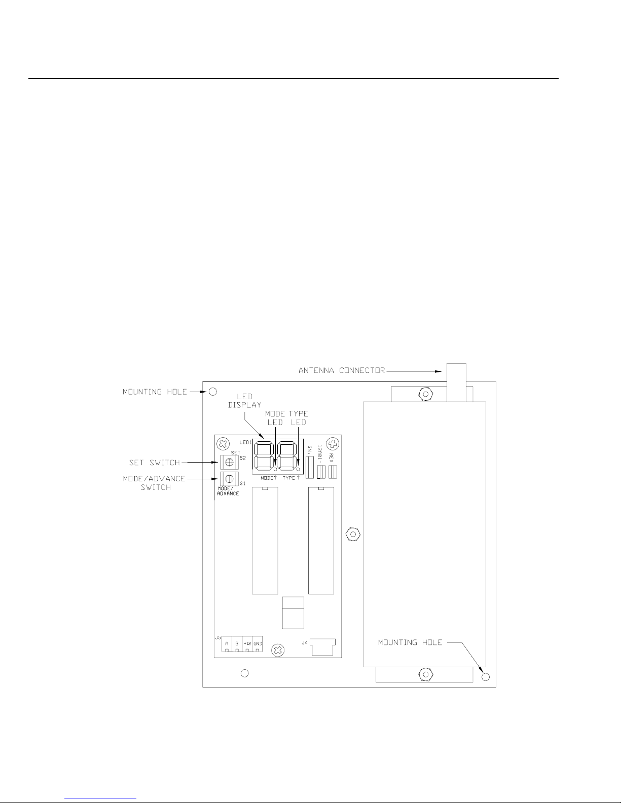
When the location of the receiver has been established, remove the cover and position the receiver
so that the antenna connector is at the top right. Mount the receiver, using supplied wall anchors
and screws, through two mounting holes (upper left and bottom right). Allow at least a 12-inch
clearance to mount the antenna. Place the cover on the receiver and install the antenna onto the
antenna connector.
Connect the receiver to the controller using 4 conductor 22 gauge or larger wire as follows:
Page 5

3
OPERATION
The two operating modes of the receiver are "Run" and "Setup".
In Run mode, with the receiver connected to and communicating with the controller, the Mode
LED should blink once per second. The receiver monitors the status of each transmitter. If the
status condition of a transmitter changes, it is reported to the receiver and the information is
updated on the LED display.
The transmitter number flashes on the display whenever a report is received from a transmitter.
The display will continually display the status of any transmitters that are violated (not ready) or
that have trouble. The transmitter number flashes on the display followed by the status
condition(s).
LED DISPLAY INFORMATION ABOUT THE LED DISPLAY
1.1
Displays the number of the transmitter with a change in condition.
A L
Displays that the current transmitter is "NOT READY".
C O
Displays that the cover was removed from the current transmitter.
S F
Displays that the current transmitter has a supervision failure.
L O
Displays that the current transmitter has reported a battery low.
NOTE: If the receiver is not communicating with the controller, the Mode LED will blink four
times per second.
SET - The Set switch is used to increment or change the current selection.
MODE /ADVANCE - The Mode/Advance switch is used to enter Setup mode, advance to the next
Setup item, and to confirm a selection. It is also used to exit Setup mode.
LED DISPLAY - The LED DISPLAY is used to show the status of each transmitter and to ensure
proper setup.
MODE LED - In Run mode, the Mode LED is used to indicate communication status with the
controller. In Setup mode, the Mode LED is used to give helpful information when entering your
code, and indicates if a transmitter sends a restore code.
TYPE LED - In Setup mode, the TYPE LED is used to give information when entering your code,
and indicates if a transmitter is supervised.
Page 6

4
SETUP MODE
The Setup Mode is used to configure the general operating parameters of the receiver, to program a
transmitter into the receiver, and to change the characteristics of a programmed transmitter. The
Mode LED does not blink in Setup mode.
To enter the Setup mode:
A. Press and hold the Mode/Advance switch for approximately two seconds.
B. Enter the four-digit code. "C" is shown on the left of the display and the digit for each code
number is shown on the right of the display.
C. The Set switch is used to increment the value of the digit.
D. The Mode/Advance switch is used to advance to the next digit of the code. The Mode and
Type LED’s are used to indicate which digit of the code is shown.
When no LED is lit, enter the first digit of the code. When the Type LED is lit, enter the second
digit. When the Mode LED is lit, enter the third digit. When both the Type and Mode LED’s are
lit, enter the fourth digit. The default code is 1111. If the correct code is entered, you will be
allowed to enter Setup mode. The receiver will return to Run mode if the wrong code is entered or
if the Mode/Advance switch is pressed for two seconds prior to entering all the digits.
Use the Set switch to increment the first digit of the code.
C 1
Use the Set switch to increment the second digit of the code.
C 1.
Use the Set switch to increment the third digit of the code.
C.1
Use the Set switch to increment the fourth digit of the code.
C.1.
After entering the code you are prompted to enter the receiver address. "A" is shown on the left of
the display and the current address is shown on the right. Pressing the Set switch changes the
address. The current address will be stored into memory when the Mode/Advance switch is
pressed. Setup mode is exited when the Mode/Advance switch is pressed for two seconds.
Next, you are prompted to enter the number of addresses. The letter "n" is shown on the left of the
display and the digit for the current number of addresses is shown on the right of the display.
Pressing the Set switch changes the number of addresses. The current number of addresses will be
stored into memory when the Mode/Advance switch is pressed. Setup mode is exited when the
Mode/Advance switch is pressed for two seconds.
The next four items allow you to change each digit of your security code. The Set switch is used to
increment the value of each digit. The Mode/Advance switch is used to enter each digit and
advance to the next.
Page 7

5
Next, the programmed characteristics of each transmitter are displayed. The transmitter number is
shown in the LED Display. If no transmitter is programmed for an address, neither the Mode LED
nor the Type LED will be lit. If a transmitter is programmed, the Mode LED indicates whether the
transmitter sends restore transmissions and the Type LED shows whether the transmitter is
supervised.
The Mode LED is on if the transmitter sends restore transmissions, and off if it doesn't.
The Type LED is on steady if the transmitter is supervised, and blinks if it isn't.
The Set switch is used to change the characteristics of a programmed transmitter. Each press of the
Set switch cycles through each combination of supervised, sends restores, or no transmitter
programmed.
The Mode/Advance switch is used to change to the next transmitter address. Setup mode is exited
by pressing the Mode/Advance switch for two seconds.
TEACHING THE RECEIVER A TRANSMITTER ADDRESS
If no transmitter is programmed for an address, a new transmitter may be programmed into that
address by activating the desired transmitter. The activated transmitter will then be entered into
that address. The transmitter must be activated by pressing the test button or by causing a violation
transmission to be sent. Pressing one of the buttons on the transmitter activates the SX TX-9x
series transmitters. Each button that will be used must be programmed as a separate transmitter.
Supervisory restores, battery low, and tamper transmissions are not learned.
Based on the type of transmitter received, the receiver will try to set the supervisory and restore
characteristics appropriately for that type of transmitter. These can be changed as desired using the
Set switch.
SX TX-9x series hand-held transmitters are set to non-supervised, restoring. SX TMD-90 motion
detectors are set to supervise, non-restoring. All other SX transmitters are set to supervise,
restoring. All S1 transmitters are set to supervise, restoring. All Megacode Transmitters are set to
non-supervised, non-restoring.
Once a transmitter is programmed into an address, the transmitter address will briefly turn off
whenever a transmission from that transmitter is received. This can be used to verify that the
correct transmitter has been programmed and is operating reliably.
NOTE: The controller ignores the current status of each transmitter while the receiver is in Setup
mode.
Page 8

6
TRANSMITTER SETUP
A. Press and hold the Mode/Advance button for two (2) seconds.
B. Enter the code (default 1111).
! To enter the first number of the code, press the SET button. "C1" will appear.
! Press the Mode/Advance button to advance to the next code number.
! Press the SET button. "C1." will appear (second number of the code).
! Press the Mode/Advance button to advance to the next code number.
! Press the SET button. "C.1" will appear (third number of the code).
! Press the Mode/Advance button to advance to the next code number.
! Press the SET button. "C.1." will appear (fourth number of the code).
C. "A1" will appear. On OmniLT and Omni, "A1" is always used. On the OmniPro system, the
address will depend on the number of expansion enclosures used. If none are used, then "A1"
will correspond (see "OmniPro Setup" for more information).
D. Press the Mode/Advance button to proceed and to save any changes.
E. Next, "n1" will appear. The value of "n" will determine the number of transmitters used.
F. Press the Mode/Advance button to proceed and to save any changes.
G. C1 will appear (the 1
st
number of the code). Pressing the SET button increments the number.
H. Press the Mode/Advance button to proceed.
I. "C1." will appear (2
nd
number of the code). Pressing the SET button increments the number.
J. Press the Mode/Advance button to proceed.
K. "C.1" will appear (3
rd
number of the code). Pressing the SET button increments the number.
L. Press the Mode/Advance button to proceed.
M. "C.1." will appear (4
th
number of the code). Pressing the SET button increments the number.
N. Press the Mode/Advance button to proceed.
O. "1" will appear (1
st
transmitter address). Trip the transmitter. When the 12A00 receives the
transmission, the 12A00 will display the digit (transmitter address) with a dot on either side
(the dots indicate the transmitter's characteristics).
P. Press the Mode/Advance button to proceed and to save the changes made.
Q. "2" will appear (2
nd
transmitter address). Trip the transmitter. When the 12A00 receives the
transmission, the 12A00 will display the digit (transmitter address) with a dot on either side
(the dots indicate the transmitter's characteristics).
R. Press the Mode/Advance button to proceed and to save the changes made.
S. Repeat for each transmitter address (1-64) until all transmitters have been programmed.
Page 9

7
RESET MEMORY
To erase all transmitters from memory and to reset to the factory default configuration, press and
hold both the Set and Mode/Advance switches simultaneously for 2 seconds. You are first
prompted to enter a code (as mentioned above). After the code is entered, the display will show
"EE". If you choose to continue, press and hold the Set and Mode/Advance switches
simultaneously for 2 seconds once again. Memory is reset at the end of the two seconds.
NOTE: If you choose not to reset memory at the "EE" display, don’t press any keys for a 10
second period and the receiver will return to Run mode.
CONNECTING TO OMNILT
Connect the "A" and "B" terminals of the 12A00 to the OmniLT (Yellow = A and Green = B).
Connect the "+12" and "GND" terminals of the 12A00 to the "AUX 12V" and "AUX GND"
terminals the OmniLT, respectively.
OmniLT Controller
12A00 Wireless Receiver
OMNILT SETUP
A. On the console, enter the "Installer Setup" menu (press 9, installer code, then #). Press 2 for
“Zones”, then press 1 # (“Wireless Receiver?” Yes = 1).
B. When connected to OmniLT, zones 9-24 are the wireless receiver zones.
C. When connected to OmniLT, the receiver address on the 12A00 must be set to "A1" and the
number of addresses must be set to "n1".
D. OmniLT can handle up to 4 transmitters per zone.
Page 10

8
The chart below shows the relationship of each wireless transmitter on the 12A00 Wireless
Receiver to each zone on the OmniLT.
Zones on OmniLT Transmitter Numbers on Wireless Receiver
Zone 09 1 17 33 49
Zone 10 2 18 34 50
Zone 11 3 19 35 51
Zone 12 4 20 36 52
Zone 13 5 21 37 53
Zone 14 6 22 38 54
Zone 15 7 23 39 55
Zone 16 8 24 40 56
Zone 17 9 25 41 57
Zone 18 10 26 42 58
Zone 19 11 27 43 59
Zone 20 12 28 44 60
Zone 21 13 29 45 61
Zone 22 14 30 46 62
Zone 23 15 31 47 63
Zone 24 16 32 48 64
Page 11

9
CONNECTING TO OMNI
Connect the "A" & "B" terminals of the 12A00 to the "A" & "B" terminals under the section
marked "Consoles" on the Omni controller. Connect the "+12" and "GND" terminals of the 12A00
to the "AUXILIARY 12V" and "AUXILIARY GND" terminals on the Omni, respectively.
Omni Controller 12A00 Wireless Receiver
OMNI SETUP
A. On the console, enter the "Installer Setup" menu (press 9, installer code, then #). Press 2 for
“Zones”, then press 1 # (“Wireless Receiver?” Yes = 1).
B. When connected to Omni, zones 17-32 are the wireless receiver zones.
C. When connected to Omni, the receiver address on the 12A00 must be set to "A1" and the
number of addresses must be set to "n1".
D. Omni can handle up to 4 transmitters per zone
Page 12

10
The chart below shows the relationship of each wireless transmitter on the 12A00 Wireless
Receiver to each zone on the Omni.
Zones on Omni Transmitter Numbers on Wireless Receiver
Zone 17 1 17 33 49
Zone 18 2 18 34 50
Zone 19 3 19 35 51
Zone 20 4 20 36 52
Zone 21 5 21 37 53
Zone 22 6 22 38 54
Zone 23 7 23 39 55
Zone 24 8 24 40 56
Zone 25 9 25 41 57
Zone 26 10 26 42 58
Zone 27 11 27 43 59
Zone 28 12 28 44 60
Zone 29 13 29 45 61
Zone 30 14 30 46 62
Zone 31 15 31 47 63
Zone 32 16 32 48 64
Page 13

11
CONNECTING TO OMNIPRO
Connect the "A" & "B" terminals of the 12A00 to the "A" & "B" terminals under the section
marked "Consoles" on the OmniPro controller. Connect the "+12" and "GND" terminals of the
12A00 to the "AUXILIARY 12V" and "AUXILIARY GND" terminals on the OmniPro,
respectively.
OmniPro Controller 12A00 Wireless Receiver
OMNIPRO SETUP
A. When connected to an OmniPro, the 12A00 is recognized as an Expansion Enclosure. The
12A00 can handle up to 64 wireless zones, in groups of 16. Each group of 16 zones is
considered 1 Expansion Enclosure.
B. On the OmniPro console, enter the “Installer Setup” menu (press 9, installer code, then #).
Press 2 for “Zones”. Press the down arrow once, then enter the number of expansion
enclosures (groups of 16 wireless zones) being used.
C. The wireless zones on the OmniPro start on zone 33 (if no hardwire expansion enclosures are
used).
D. The 12A00 address is set at 1 (A1) (if no expansion enclosures are used).
E. If the OmniPro has 1 expansion enclosure, the wireless zones start on zone 49.
The 12A00 address is then set to 2 (A2).
F. If the OmniPro has 2 expansion enclosures, the wireless zones start on zone 65.
The 12A00 address is then set to 3 (A3).
G. If the OmniPro has 3 expansion enclosures, the wireless zones start on zone 81.
The 12A00 address in then set to 4 (A4).
Page 14

12
The chart below describes where each group of wireless transmitters (groups of 16) on the 12A00
Wireless Receiver relates to each group of zones (groups of 16) on the OmniPro in accordance with
the number of addresses assigned (n1-4).
Zones on OmniPro (in groups of 16)
Zones 33-48 Zones 49-64 Zones 65-80 Zones 81-96
n1
Transmitters:
1-16, 17-32, 33-48, and 49-64
n2
Transmitters:
1-16 and 33-48
Transmitters:
17-32 and 49-64
n3
Transmitters:
1-16 and 49-64
Transmitters:
17-32
Transmitters:
33-48
n4
Transmitters:
1-16
Transmitters:
17-32
Transmitters:
33-48
Transmitters:
49-64
HAI CONTROLLER INDICATIONS
When the condition of a transmitter changes state, the HAI controller will display that condition as
follows:
Transmitter Condition OmniLT - Omni - OmniPro
When a transmitter (zone) is violated Zone Name "NOT RDY"
When a cover is removed from a transmitter Zone Name "NOT RDY"
When a supervisory failure is reported Zone Name "TRBL NOW"
When a battery low is reported Zone Name "HAD TRBL"
Page 15

13
FCC NOTICE
This device complies with FCC Rules Part 15. Operation is subject to the following two
conditions: (1) This device may not cause harmful interference, and (2) This device must accept
any interference received, including interference that may cause undesired operation.
Verified to comply with the limits of a Class B digital device pursuant to Part 15 of the FCC Rules.
Page 16

QUICK-REFERENCE SETUP GUIDE
To Enter Setup mode, press and hold the Mode/Advance switch for 2 seconds.
DISPLAY DESCRIPTION SET SWITCH MODE/ADVANCE SWITCH
C 0
Enter the first digit of the code Increments the digit (0-9) Advances to the next digit
C 0.
Enter the second digit of the code Increments the digit (0-9) Advances to the next digit
C.0
Enter the third digit of the code Increments the digit (0-9) Advances to the next digit
C.0.
Enter the fourth digit of the code Increments the digit (0-9) Advances to the next item
A 1
Enter the receiver address Changes the current address (1-8) Advances to the next item
n 1
Enter number of addresses Changes number of addresses (1-4) Advances to the next item
C 1
Displays the first digit of the code Changes the current digit (0-9) Advances to the next digit
C 1.
Displays the second digit of the code Changes the current digit (0-9) Advances to the next digit
C.1
Displays the third digit of the code Changes the current digit (0-9) Advances to the next digit
C.1.
Displays the fourth digit of the code Changes the current digit (0-9) Advances to the next item
1
Displays the status of transmitter 1 Changes characteristics of transmitter Advances to the next transmitter
2
Displays the status of transmitter 2 Changes characteristics of transmitter Advances to the next transmitter
3
Displays the status of transmitter 3 Changes characteristics of transmitter Advances to the next transmitter
Characteristics of Transmitters:
DISPLAY MODE LED TYPE LED DESCRIPTION OF THE DISPLAY
1
OFF OFF No transmitter is programmed at this address
1
*
OFF BLINKS This transmitter is not supervised and doesn't send restore transmissions
.1
*
ON BLINKS This transmitter is not supervised but sends restore transmissions
1.
OFF ON This transmitter is supervised but doesn't send restore transmissions
.1.
ON ON This transmitter is supervised and sends restore transmissions
To reset memory, press and hold the Set and Mode/Advance switches together for 2 seconds.
DISPLAY DESCRIPTION SET SWITCH MODE/ADVANCE SWITCH
C 0
Enter the first digit of the code Increments the digit (0-9) Advances to the next digit
C 0.
Enter the second digit of the code Increments the digit (0-9) Advances to the next digit
C.0
Enter the third digit of the code Increments the digit (0-9) Advances to the next digit
C.0.
Enter the fourth digit of the code Increments the digit (0-9) Advances to the next item
E E
Erase EEPROM ? (Reset Memory) Press and hold Set & Mode/Advance switches together for 2 seconds
 Loading...