

Page 1
S
S
E
E
R
R
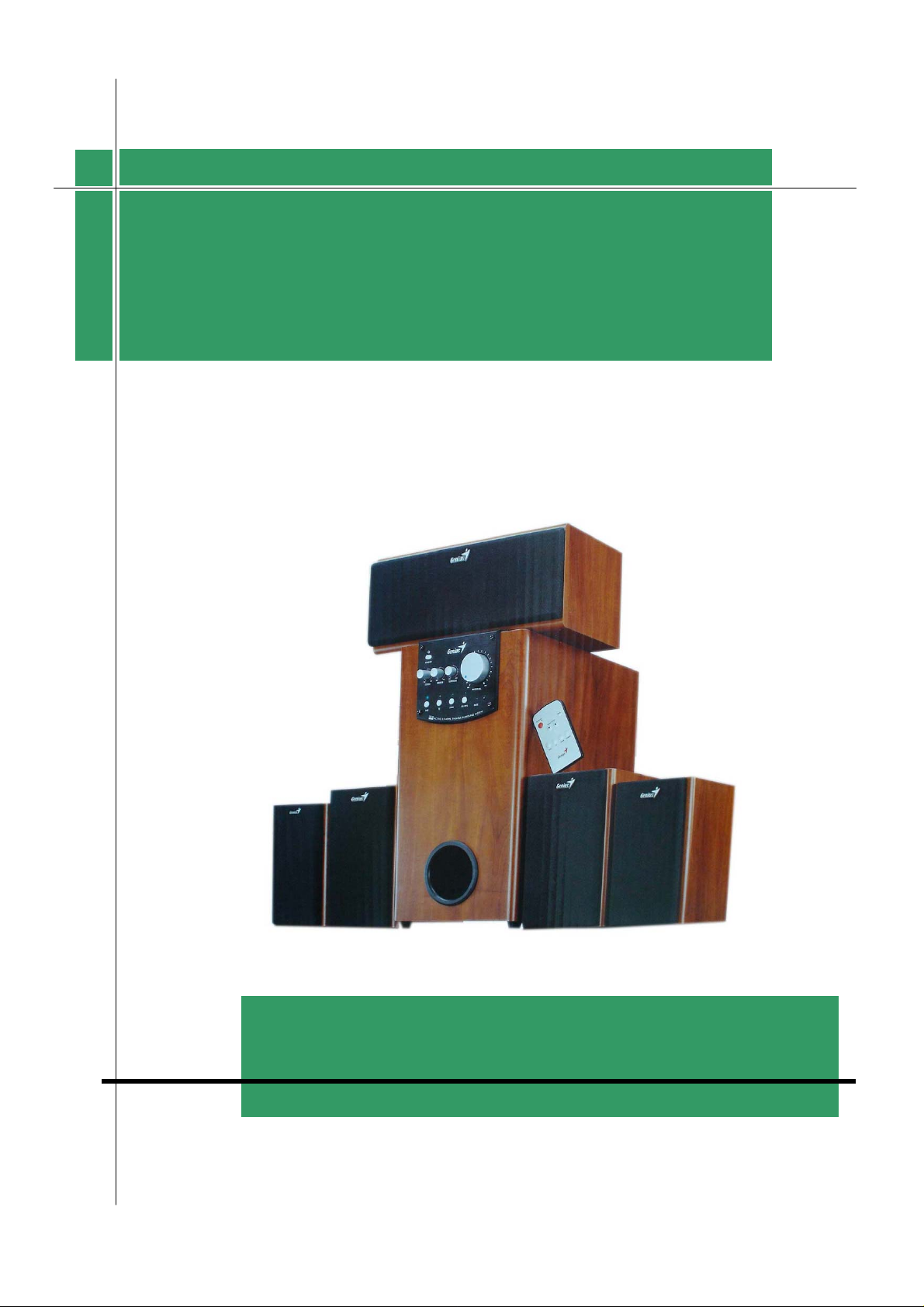
KYE SYSTEMS CORP.
VII
V
C
C
E
E
G
G
UII
U
D
D
E
E
SSWW--HHFF55..11 5500000
Version:1.0
Total 26 Pages (Cover Page included)
0
Page 2
ervice
S
s
G
uide
Revision History
Version Date Changes
W-HF5.1 5000
1.0
Official Release
Version: 1.0 Page 1/25
Page 3

s
S
ervice
W-HF5.1 5000
G
uide
Table of Contents
Revision History
Table of Contents………………………………………………… ………….2
Getting Started………………………………………………… ……….……………....3
Conventions Used in this Guide………………… ………...……………….3
Safety Precautions……………………………… ………………...………..3
Chapter1. How to Handle Defective Returns………………… ……………………….4
1.1 Overview……………………………………………………………….4
1.2 Problems………………………………………………………………..5
……………………………………………………………… ……..1
1.2.1 Power LED (indicator) Unlighted………………...……………......6
1.2.2 Does not work or one channel no sound……………………….…..7
1.2.3 Noise……………………………………………………………….7
Chapter2. Specifications………………………………………………………………..8-9
Chapter3. Block Diagram……………………………………………………………....10
Chapter4. Exploded View…………………………………………………………….…11-14
Chapter5. Part List……………………………………………………………………..15-18
Chapter6. Important Notes…………………………………………………………....19
6.1 Packing Requirement for sending the PCB Assembly by post……….…19
6.2 Short of Spare Parts while Repairing a Speaker System…………….….19
Chapter7. Circuit Schematic……………………………………………………………20-25
Version: 1.0 Page 2/25
Page 4
ervice
S
s
G
uide
Getting Started
Conventions Used in this Guide
Pay Special Attention: Instructions that are important to
Attention
remember and may prevent mistakes.
Caution: Information that, if not followed, may result in
damage to the product.
W-HF5.1 5000
Safety Precautions
The following precautions should be observed in handling the speaker described in this guide:
Place the speakers on a flat level and stable surface.
Do not place the speakers in environments subject to mist, smoke, vibration, excessive dust,
salty or greasy air, or other corrosive gases and fumes.
Do not drop or jolt the speakers.
Do not allow anything to drop into the subwoofer case through its ventilator, as it could
result in fatal electric shock or fire.
Place the unit far enough from other equipments for good heat dissipation.
Disconnect the AC power cord from the AC outlet before performing any maintenance on the
speakers.
Do not perform any maintenance with wet hand.
Prevent foreign substance, such as water, other liquids or chemicals, from entering the
speakers while performing maintenance procedures on the speakers.
Version: 1.0 Page 3/25
Page 5
S
p
ervice
s
G
uide
Chapter 1. How to Handle Defective Returns
W-HF5.1 5000
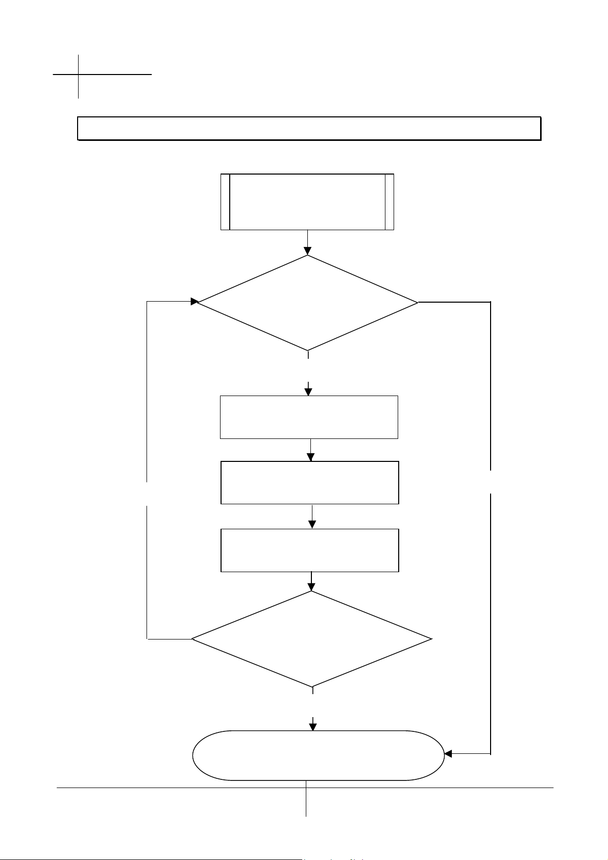
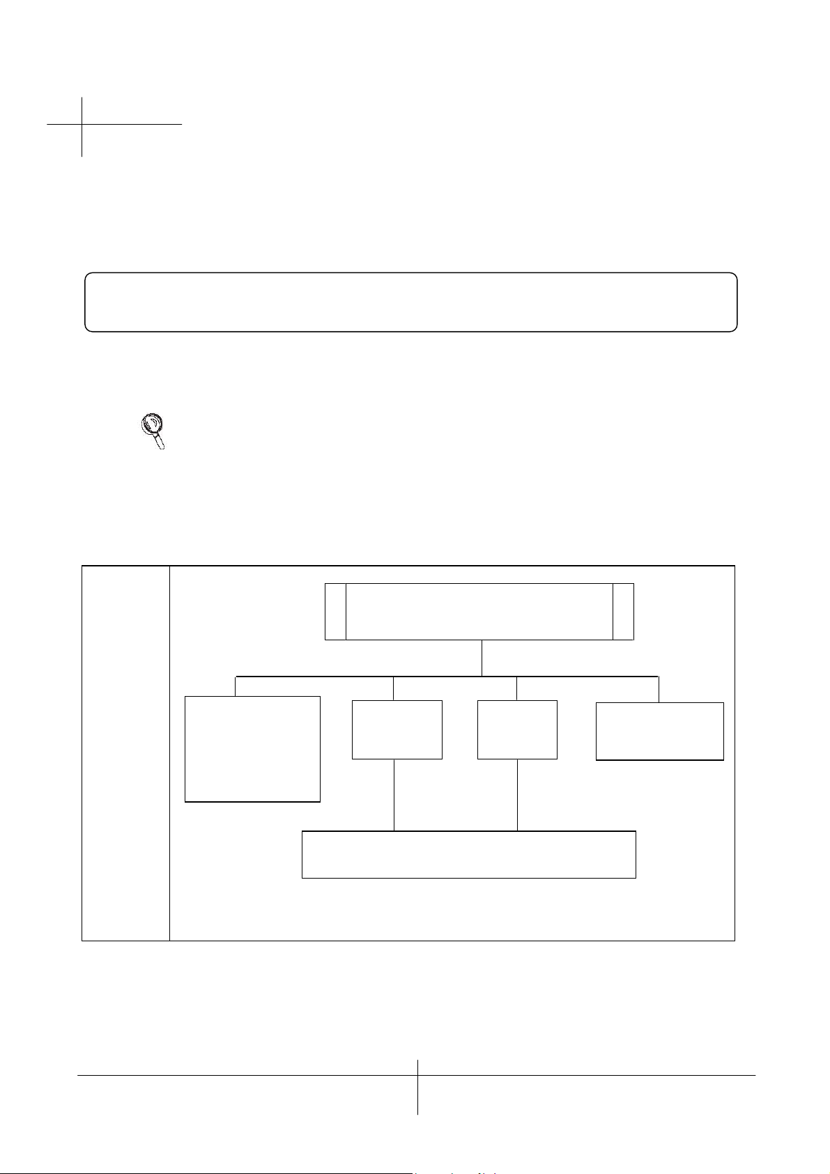
1.1 Overview
Receiving Defective
Speakers
from Customers
Verifying problems&
Proceeding necessary tests
Functioning NG
Analyzing possible
Malfunction causes
Functioning NG
Deciding & proceeding
the rectification methods
Functioning OK
Replacing necessary
Defective parts
Proceeding tests
To verify if the speaker is
functioning normally
Pro
Version: 1.0 Page 4/25
Functioning OK
Return the speakers with
er repackaging to customers
Page 6

S
ervice
s
G
uide
1.2 Problems
Item Problem descriptions
1.2.1 Power LED (indicator) unlighted
1.2.2 Does not work or one channel no sound
1.2.3 Noise
W-HF5.1 5000
Version: 1.0 Page 5/25
Page 7
ervice
S
r
s
G
uide
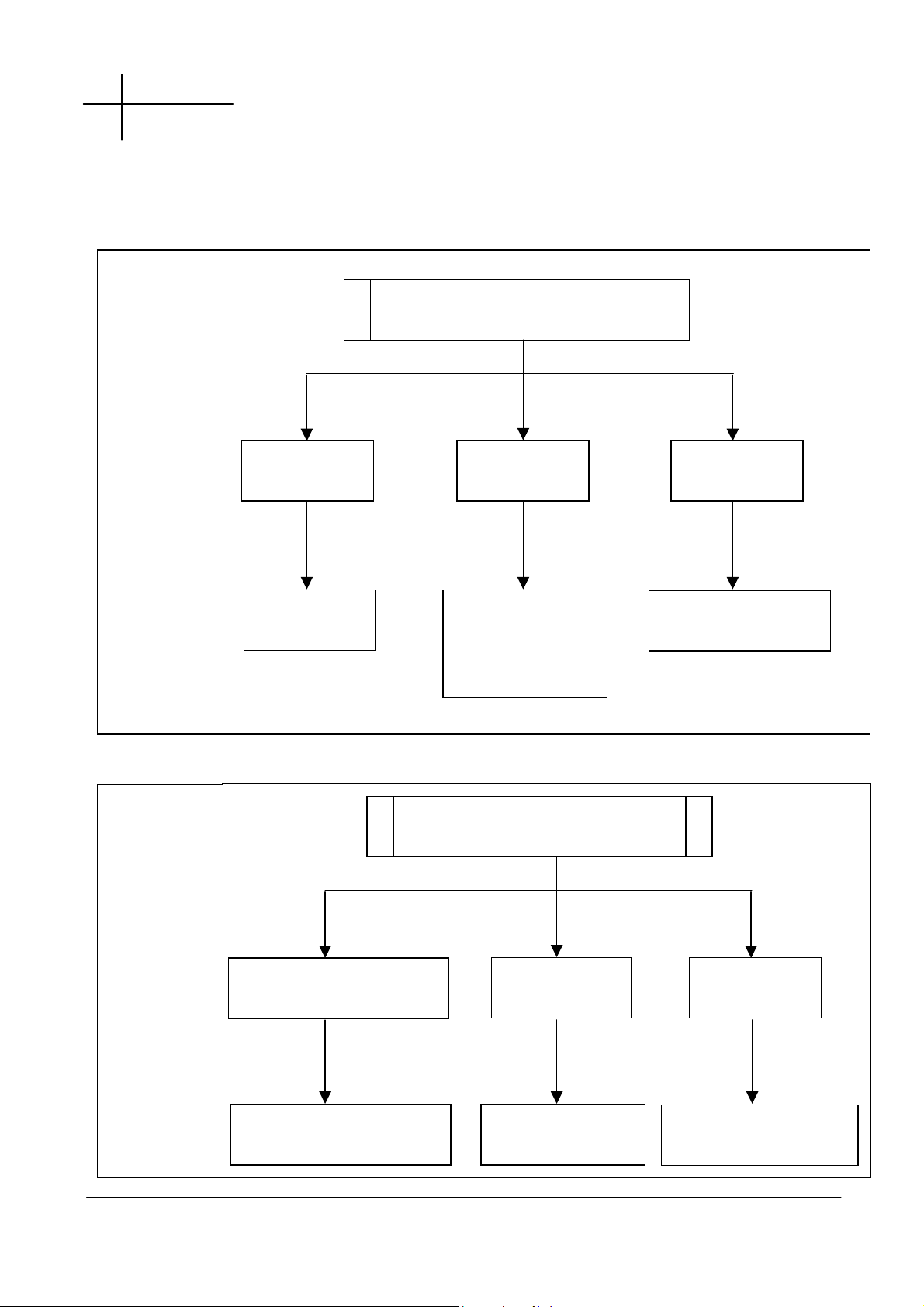
Please follow the numbered sequence marked within parenthesis given in individual
Flow chart, in that this is the best-recommended sequence to rectify the problems.
Attention
W-HF5.1 5000
1.2.1 Power LED (indicator) unlighted
Problem
Analyze
and
Identify
the Causes
Solutions
Secondary wire Of
transformer is
Disconnedcted of
defective
Power LED (indicator)unlighted
IC SN8P27
14KB
Resolder or replace defective component(s)
IC 78L05
burnt
Defective powe
Switch or LED
Version: 1.0 Page 6/25
Page 8
s
S
r
r
ervice
G
uide
W-HF5.1 5000
1.2.2 Does not work or one channel no sound
Problem
Analyze and
Identify the
Causes
Solutions
Defective
Audio cable
Replace
Audio cable
Does not work or
One channel no sound
Broken o
Short circuit
Check solde
Points on PCB
And resolder
defective one(s)
Defective IC
Check and replace
Defective IC
1.2.3 Noise
Problem
Analyze and
Identify the
Causes
Solutions
Component(s) around
IC is/are defective
Check and replace
defective component(s)
Version: 1.0 Page 7/25
Noise
Defective VR Defective IC
Replace
Defective VR
Replace defective IC
Page 9

ervice
S
s
G
uide
Chapter 2. Specifications
Satellite
W-HF5.1 5000
No. DESCRIPTION
1. RATED OUTPUT POWER @THD 10% W 19 19 19 19 19
2
SENSITIVITY(1KHz)@RATED O/P
POWER
3 SENSITIVITY(1KHz)@1W O/P POWER mV 76 130 130 76 76
4 MAX INPUT LEVEL@1%
5 FREQUENCY RESPONSE(1KHz=0dB)
110Hz dB -0.3
1K dB 0
135K dB -3
6 S/N @RATED O/P POWER dB 75
7 CHANNEL UNBALANCE @REF O/P
POWER
8 CHANNEL SEPARATION(ONE
CHANNEL IN; OTHER CHANNEL INPUT
SHORTING)
9 HUM NOISE (VR MAX)
(VOLUME MAX; INPUT SHORTING)
10 HUM NOISE (VR MIN)
(VOLUME MIN. INPUT SHORTING)
THD mV 290 500 500 290 290
UNIT
CEN FR FL SR SL
mV 380 640 640 380 380
dB 0.2 0.2 0.2 0.2 0.2
dB 55 55 55 55 55
mV 2 2 2 2 2
mV 0.1 0.1 0.1 0.1 0.1
NOMINAL LIMIT
±5%
±10%
±10%
±10%
±0.5
±0.5
±0.5
≥60
≤0.5
≥40
≤3
≤1
Version: 1.0 Page 8/25
Page 10

ervice
S
s
G
uide
Chapter 2. Specifications
Subwoofer
W-HF5.1 5000
No. DESCRIPTION
1. RATED OUTPUT POWER @100Hz ( 10%THD) W 75
2
3 SENSITIVITY(1KHz)@1W O/P POWER mV 10
4 MAX INPUT LEVEL @ 1%
5 DISTORTION @100Hz REF. O/P POWER % 0.17
6 CROSSOVER FREQUENCY
LOW Hz 0
HI Hz 140
7 S/N RATIO @100Hz RATED O/P POWER dB 75
8 VR MIN NOISE mV 0.5
9 VR MAX NOISE & HUM mV 4
SENSITIVITY(100Hz)@RATED O/P POWER
THD mV 85
UNIT
mV 100
NOMINAL LIMIT
±5
±10
±5
±8
≤0.5
±20
±20
≥60
≤3
≤10
Version: 1.0 Page 9/25
Page 11

S
ervice
s
G
uide
Chapter 3. Block Diagram
W-HF5.1 5000
Version: 1.0 Page 10/25
Page 12

ervice
S
s
G
uide
Chapter 4. Exploded View
Subwoofer
W-HF5.1 5000
Version: 1.0 Page 11/25
Page 13

ervice
S
s
G
uide
Chapter 4. Exploded View
Center
W-HF5.1 5000
Version: 1.0 Page 12/25
Page 14

ervice
S
s
G
uide
Chapter 4. Exploded View
W-HF5.1 5000
Satellite(Front)
Version: 1.0 Page 13/25
Page 15

ervice
S
s
G
uide
Chapter 4. Exploded View
Satellite(Rear)
W-HF5.1 5000
Version: 1.0 Page 14/25
Page 16

ervice
S
s
G
uide
Chapter 5. Part List
Subwoofer
W-HF5.1 5000
Ref. No.
1
2
3
4
5
6
7
8
9
10
11
12
13
14
15
16
17
18
19
20
21
22
23
24
25
26
Description
Screw, HSAΦ3.5×16,Black
Knob, SW-HF5.1 5000A,Silver Color HIPS
Knob, SW-HF5.1 5000A,Silver Color HIPS
Flash PCB
Front panel, SW-HF5.1 5000A, Black Color ABS
Keystroke, SW-HF5.1 5000A, Silver Color HIPS
Keystroke, SW-HF5.1 5000A, Silver Color HIPS
STAND-BY
MCU, SW-HF5.1 5000A,
Control PCB, SW-HF5.1 5000A,
Wood-box(SUB), SW-HF5.1 5000A, 12T MDF
Speaker, 6.5" 8Ω 75W
Buckle, SW-HF5.1 5000A, Black PA
Safety, SW-HF5.1 5000A, Black
Switch Power, SW-HF5.1 5000A, Black
Input Panel, SW-HF5.1 5000A
Function PCB Assembly
IC TDA7269A
IC TDA7294
Cooler, SW-HF5.1 5000A, Black AL
Function PCB Assembly
Rear Panel, SW-HF5.1 5000A,Black Color SPCC
Out Put, SW-HF5.1 5000A,
Transformer, EI7642 I/P:240V ,W-HF5.1 5000A
Rubber Foot, SW-HF5.1 5000A,
Duct, SW-HF5.1 5000A, Black Color HIPS
RS Part No. Part No.
4102H35016A02G01
0107HIPS81002G01
0107HIPS81008G01
180615094V001G01
01020ABS04064G01
0107HIPS81001G02
0107HIPS81003G01
180215094V001G02
180215094V001G01
180315094V001G01
9401040014000G01
084075086B212G01
011600PA00003G01
0121OABS09000G01
2460250060001G01
180415094V001G01
180115094V001G02
211TDA7269ACHG01
2110TDA7294CHG01
0405011001615G01
180115094V001G01
0402031001755G01
181015094V001G01
2225400030001G02
4311000016003G01
0106HIPS00112G01
Version: 1.0 Page 15/25
Page 17

ervice
S
s
G
uide
Chapter 5. Part List
Center
W-HF5.1 5000
Ref. No.
1
2
3
4
5
6
7
8
9
10
11
Description
Badge, SW-HF5.1 5000A, Black Color AL
Cloth, Black Color,
Cloth Frame, Black Color MDF
Metal Stud, SW-HF5.1 5000A, Black HIPS
Grommet, SW-HF5.1 5000A, Black Color RUBBER
Speaker, 4" 4Ω 15W
Wood-box, SW-HF5.1 5000A, MDF
Paper tube,Black Color PAPER
Terminal, SW-HF5.1 5000A, Black Color HIPS
Speaker, 1" 8Ω 10W, Black Color
Foot, SW-HF5.1 5000A,One side tape glue, Black Color
RS Part No. Part No.
0406031101005G01
0701003801800G01
9110420180300G01
01220HIPS0002G01
0810150404312G01
9411040012200G01
2032123016821G01
0820100801312G01
4311015540004G01
Version: 1.0 Page 16/25
Page 18

ervice
S
s
G
uide
Chapter 5. Part List
W-HF5.1 5000
Satellite(Front)
Ref. No.
1
2
3
4
5
6
7
8
9
10
11
Badge, SW-HF5.1 5000A, Black Color AL
Cloth, Black Color,
Cloth Frame, Black Color MDF
Metal Stud, SW-HF5.1 5000A, Black HIPS
Grommet, SW-HF5.1 5000A, Black Color RUBBER
Speaker, 4" 4Ω 15W
Speaker, 1" 8Ω 10W
Wood-box, SW-HF5.1 5000A, 9T MDF
Paper tube, Black Color, Paper
Terminal, SW-HF5.1 5000A, Black Color HIPS
Foot, SW-HF5.1 5000A,One side tape glue, Black Color
Description
RS Part No. Part No.
0406031101005G01
0701002601700G01
9110420180250G01
01220HIPS0002G01
0810150804312G01
0820100801312G01
9411040011800G01
2032123016821G01
4311015540004G01
Version: 1.0 Page 17/25
Page 19

ervice
S
s
G
uide
Chapter 5. Part List
W-HF5.1 5000
Satellite(Rear)
Ref. No.
1
2
3
4
5
6
7
8
9
10
11
12
Badge, SW-HF5.1 5000A, Black Color AL
Cloth, Black Color,
Cloth Frame, Black Color 9T MDF
Metal Stud, SW-HF5.1 5000A, Black HIPS
Grommet, SW-HF5.1 5000A, Black Color RUBBER
Speaker, 3" 8Ω 15W
Speaker, 1" 8Ω 10W
Wood-box, SW-HF5.1 5000A, 9T MDF
Metal panel, SW-HF5.1 5000A, Black Color SPCC
Paper tube, Black Color, Paper
Terminal, SW-HF5.1 5000A, Black Color HIPS
Rubber Foot, One side tape glue, Black Color
Description
RS Part No. Part No.
0406031101005G01
0701001701600G01
9110420180200G01
01220HIPS0002G01
0810150803112G01
0820100801312G01
9411040011600G01
0404010301004G01
2032123016821G01
4311015540004G01
Version: 1.0 Page 18/25
Page 20

ervice
S
s
G
uide
Chapter 6. Important Notes
6.1 Packing requirement for sending the PCB assembly by post
PCB assembly is a kind of sophisticated electronic circuit board. Well packing
Will be required when sending them by post.
*Some sophisticated IC components are mounted on the PCB assembly, hence
it is necessary to pack each PCB assembly with a separate static protecting bag,
in order to avoid static electricity.
*Reliable external packing is also very important when sending the PCB assembly
by post, in that it would avoid unnecessarily lost or damage.
W-HF5.1 5000
6.2 Short of spare parts while repairing a speaker system
If you are short of spare parts when you have some spesker systems waiting to
be repaired,it would be recommended to take the necessary parts from one
Speaker system,so that you may haye the as many speaker systems
Version: 1.0 Page 19/25
Page 21

ervice
S
s
G
uide
Chapter 7. Circuit schematic
1
W-HF5.1 5000
Version: 1.0 Page 20/25
Page 22

ervice
S
s
G
uide
Chapter 7. Circuit schematic
2
W-HF5.1 5000
Version: 1.0 Page 21/25
Page 23

ervice
S
s
G
uide
Chapter 7. Circuit schematic
3
W-HF5.1 5000
Version: 1.0 Page 22/25
Page 24

ervice
S
s
G
uide
Chapter 7. Circuit schematic
4
W-HF5.1 5000
Version: 1.0 Page 23/25
Page 25

ervice
S
s
G
uide
Chapter 7. Circuit schematic
5
W-HF5.1 5000
Version: 1.0 Page 24/25
Page 26

ervice
S
s
G
uide
Chapter 7. Circuit schematic
6
W-HF5.1 5000
Version: 1.0 Page 25/25
 Loading...