

Page 1
Important - Please read these instructions fully before starting assem bly
If you need help or have damaged or missing parts, call the Customer Helpline:
Assembly Instructions - Please keep for future reference
1447954
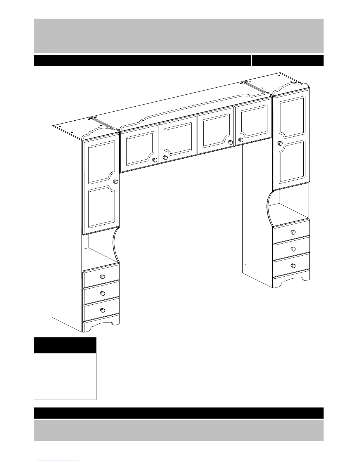
Nordic - Overbed fitment
03456 400 800
- 02-06-2014
Dimensions
Width : 248,9 cm
Depth : 49,0 cm
Height : 191,3 cm
34 4670 050
Page 2

Important - Please read these instructions fully before starting assembly
Safety and Care Advice
• Check you have all the
components and tools listed on
pages 3 and 4.
• Remove all fittings from the
plastic bags and separate them
into their groups.
• Keep children and animals
away from the work area, small
parts could choke if swallowed.
• Make sure you have enough
space to layout the parts before
starting.
• Do not stand or put weight on
the product, this could cause
damage.
• Assemble the item as close to
its final position (in the same
room) as possible.
• Assemble on a soft level
surface to avoid damaging the
unit or your floor.
• Parts of the assembly will be
easier with 2 people.
• We do not recommend the use
of power drill/drivers for
inserting screws, as this could
damage the unit. Only use hand
screwdrivers.
• Dispose of all packaging
carefully and responsibly
.
• This product should not be
discarded with household
waste. Take to your local
authority waste disposal centre.
• From time to time check that
there are no loose screws on
this unit.
• Only clean using a damp cloth
and mild detergent, do not use
bleach or abrasive cleaners.
Care and maintenance
Note: if required the next
page can be cut out and used
as reference throughout the
assembly. Keep this page with
these instructions for future
reference.
2
Page 3
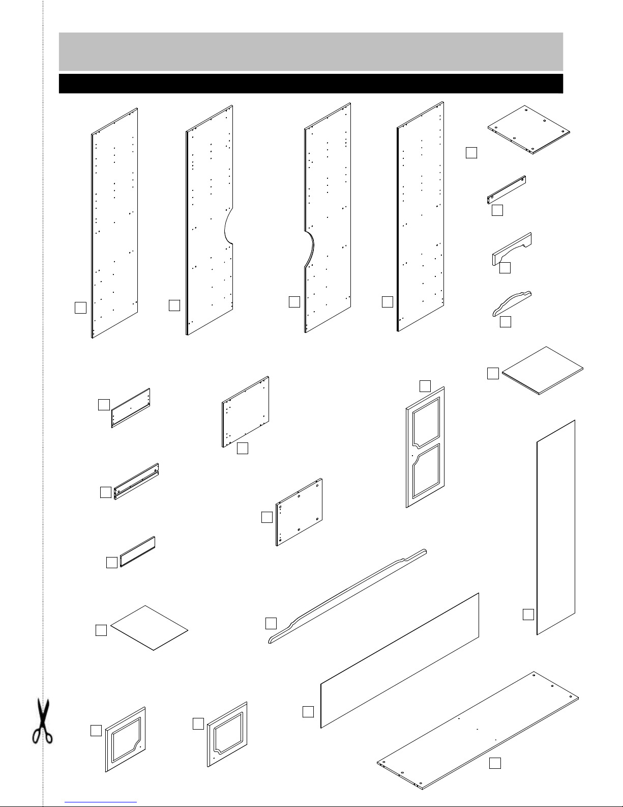
Drawer side, right/left x12
S120654
450x98x12 mm
Drawer front x6
V155811
395x157x15 mm
Drawer back x6
S120650
351x98x12 mm
Drawer bottom x6
NM415861
361x447x3 mm
Back x2
NM415853050F
1741x397x3 mm
Top/bottom x2
V155862
1633x470x15 m m
Top x6
V155863
383x470x15 mm
Top rail
V155804
1644x80x15 mm
Top rail x2
V155805
394xx15 mm
Door, Left x2
V155825
381x409x15 mm
Door, right x2
V155871
381x409x15 mm
Side left/right x2
V155845
399x475x15 mm
Plinth, front x2
V155802
395x96x15 mm
Divider x1
V155831
369x470x15 mm
Shelf x4
V155815
383x460x15 mm
Back
NM415855
1647x397x3 mm
plinth, back x2
P155865
383x60x15 mm
Door left/right x2
V155826
893x395x15 mm
Side Right
V155840
1833x475x15 mm
Side Left
V155844
1833x475x15 m m
Left divider
V155867
1833x475x15 m m
Right divid er
V155868
1833x475x15 mm
Please check you have all the panels listed below
Components - Panels
3
If you have damaged or missing components, call
the Argos Customer Helpline:
03456 400 80 0
1
2
3 4
5
6
7
8
10
11
12
13
9
14
15
16
23
17
22
20
21
1
8
Page 4
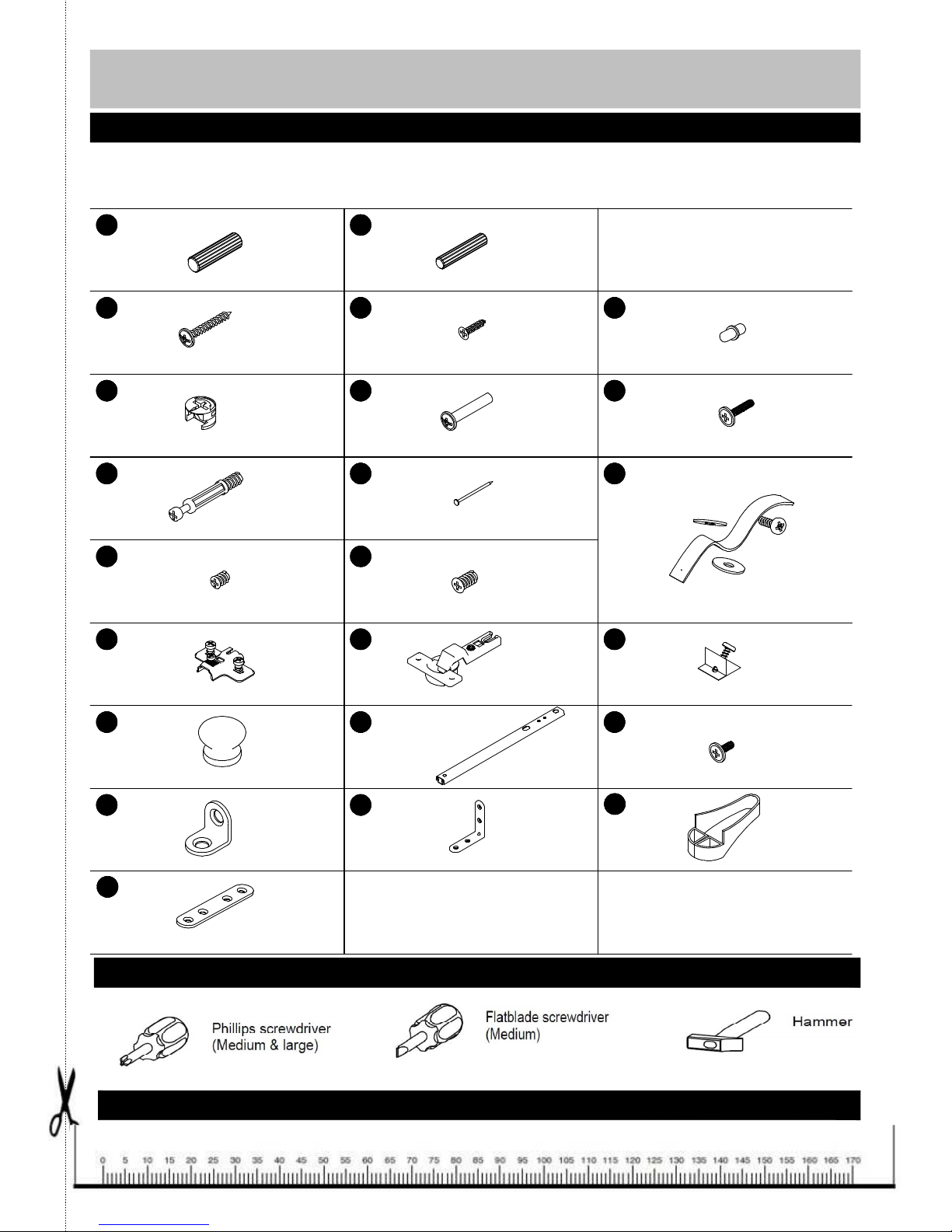
BA10240
ø6,1x11,5 mm screw x16
BA10801
20x20x2 angle x8
BA10170
ø4,0x35 mm screw x36
BA10833
15x15x10 mm x12
BA10468
ø40x30 mm Wooden knob x12
BA10400
ø6x30 mm wooden dowel x24
BA10590
ø15x9,5 mm cam x70
BA10603
ø5/11x34 mm bolt x70
BA10390
ø8x30 mm wooden dowel x36
BA10270
ø5,8x8 mm screw x36
BA10050
ø3,5x15 mm screw x72
BA10815
50x50x2 mm an gle x8
BA10025
ø1,2x20 mm nail x150
BA10191
M4x9 m m screw x12
BA10508
ø26 cup hin ge x12
BA10532
0 m m/37 m m crossplate x12
BA182002
wallstrap and instruction x2
Ba10688
500x250x Nail holder x1
B14359
17x246 mm Drawer runner x12
BA10796
80x15x2 mm connection plate x4
BA10830
5/5 mm shelf support x24
BA10233
ø4,9/M4x27 mm asambly screw x8
BA10215
M4x16 mm screw x8
Please check you have all the panels listed below
Components - Fittings
If you have damaged or missing components, call
the Argos Customer Helpline: 0845 640 30 30
Note: The quantities below are the correct amount to complete the assembly. In some cases more
fittings may be supplied than are required.
Tools required
Ruler - Use this ruler to help correctly identify the screws
A B
R T L
J
i
D
NMC
K E
4
P
Q
F
G S H
V
W
Y
Y
d
Page 5

Step 1
Assembly Instructions
Fix the drawer sides 11
to the drawer back 12 as
shown, using screws R.
Knock down the dowels
B into the holes indicated
on the drawer sides 11,
using a small hammer.
Step 2
Step 3
Slide the drawer bottom
13 into the drawer sides
11
Step 4
Screw the bolts D into
the holes indicated on
the drawer fronts 10.
5
R
R
R
B
B
B
B
D
D
11
11
11
11
11
11
12
13
10
x6
x6
x6
x6
Page 6
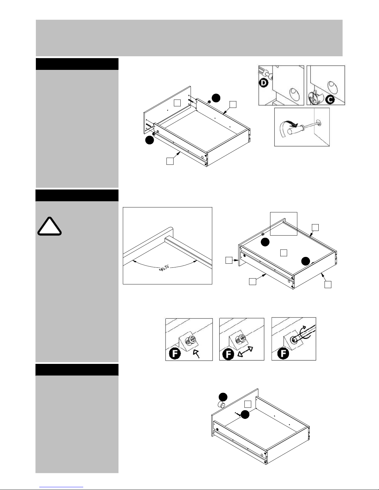
Assembly Instructions
Push the drawer front 10
onto the the drawer
sides 11 as shown.
Push cams C into the
holes indicated. Arrow
pointing towards the
front.
Turn the cams C to the
right to fix the front 10.
Step 5
Step 6
Step 7
Important!
Make sure the
angle between
the drawer front
Fix the wooden knobs G
to the drawer front 10
using screws R.
6
10 and the dra wer sides
11 is 90° be fore th e
draw er bottom is fixed.
Fix the drawer bottom
13 to the draw er back
12 and the dra wer front
10 using F.
To adjust the an gle
betw een the drawer
sides and the drawer
front push the fitting F
sidewards. See details.
!
C
C
F
F
G
R
11
11
11
11
10
10
10
13
12
x6
x6
x6
Page 7

Assembly Instructions
Knock down the dowels
A into the holes
indicated on the back
plinths 6 and the
top/bottom 5 using a
small hammer.
Step 8
Step 9
Fix the crossplates P to
the sides 1 and 4 using
the premounted screws.
See details.
Position the crossplate
exactly as sho wn.
See details.
Fix the angles V to the
sides 1, and 4 an d the
divid er 2 and 3 u sing
screws E. Place the
angles as shown.
See details.
7
Screw the bolts D into
the holes indicated on
the sides 1 and 4 and
the divider 2 and 3
A
A
A
A
A
A
6
5
x6
x2
1
1
2
3
4
4
P
P
P
P
P
P
D
D
D
D
D
D
D
D
D
D
D
D
D
D
D
D
D
D
D
D
D
D
D
D
D
D
D
D
D
D
D
D
D
D
D
D
D
D
D
D
V
V
V
V
V
V
V
V
V
V
V
V
E
E
E
E
E
E
E
E
E
E
Page 8

Assembly Instructions
Slide the top of the
drawer runners S
backwards.
Fix the front end of the
drawer runners S to the
sides 1 and 4 and the
divider 2 and 3 using
screws K into the holes
indicated.
See details.
Step 10
Step 11
Slide the top of the
drawer runners S
forwards.
Fix the backend of the
drawer runners S to the
sides 1 and 4 and the
divider 2 and 3 using
screws K into the holes
indicated.
See details.
8
1
2
3
4
S
S
S
S
S
S
S
S
S
S
S
S
S
S
K
K
K
K
K
K
K
K
K
K
K
K
K
K
K
K
K
K
K
K
K
K
K
K
K
K
K
K
3
1
2
4
S
S
S
S
S
S
S
S
S
S
S
S
S
S
K
K
K
K
K
K
K
K
K
K
K
K
K
K
Page 9

Assembly Instructions
Place the sides 1 and 4
and the divider 2 and 3
onto the bottoms 5 and
the back plinths 6.
Push the cams C into the
holes indicated. Arrow
pointing towards sides.
Turn the cams C to the
right to fix the sides 1
and 4 and the divider 2
and 3.
Step 12
9
1
2
3
4
5
5
5
5
5
5
6
6
C
C
C
C
C
C
C
C
C
C
C
C
C
C
C
C
C
C
C
C
C
C
Page 10

Assembly Instructions
Place the back 16 into
the rebates in the
sides/divider 1, 2, 3 and
4.
Step
13
10
!
Im portan t!
Make sure the
angle b etween
the top and the
sides is 90° when
the back is
attached.
Fix the backs to th e
sides/ divider 1, 2, 3
and 4 and the top 5 a nd
the back plinth 5 u sing
nails i.
Use Nail holder Yd and a
sm all h am m er.
Place the front plinths 7
as sh ow n.
Fix the front plinths 7 to
the sides/divider 1, 2, 3
and 4 u sing screws E
into the angle s V.
1
2
3
4
6
6
7
7
16
16
i
i
i
i
i
i
i
i
i
i
i
i
V
V
V
V
V
V
E
E
E
E
E
E
E
E
Page 11

Assembly Instructions
Place the top rail 8 onto
the top 5.
Fix the top rail to the top
using angles W and
screws T.
Step 14
Step 15
11
Fix the crossplates P to
the divider 21 on both
sides and to the sides
20, using th e
pre-mounted screw s.
Poistion exactly as
show n.
See details.
Screw the bolts D into
the holes indicated on
the sides 20 and th e
top/bottom 23.
Kn ock down the do wels
A into the h oles
indicated on the
top/bottom 23 using a
sm all h am m er.
x4
5
5
5
8
8
8
T
T
T
T
T
TT
T
T
T
T
T
T
T
T
T
T
T
T
T
Y
Y
Y
Y
Y
21
21
20
23
P
P
P
P
P
P
x2
x2
P
D
D
D
D
D
D
D
D
D
A
A
A
A
Page 12

Assembly Instructions
Place the top/bottom 23
onto the divider 21 as
shown. Note the
chamfered edges.
Push cams C into the
holes indicated. Arrows
pointing towards the
top/bottom 23.
Turn th e cams C to the
right to fix the
top/bottom s 23
Step 16
Step 17
Place the sides 20 onto
the top/bottom 23. Not
the rebates.
Push ca ms C into the
holes indica ted. Arro ws
pointin g towa rds the
sides.
Turn th e cams C to the
right to fix the sides.
12
23
23
23
23
21
20
20
C
C
C
C
C
C
C
C
C
C
C
C
Page 13

Assembly Instructions
Place the back 17 into
the rebates in the sides
20 and onto the
top/bottom 23.
Step 18
Step 19
Fix the connecting plates
Y
onto the top 23 using
screws T.
Place the connecting
plate exactly as shown.
See details.
13
!
Important!
Make sure the
angle between
the top and the
sides is 90° when
the back is
attached.
Fix the back 17 to the
sides 20 and the
top/bottom 23
usin g
nails i.
Use the nailholder Yd
and a small hammer.
Place the top rail 22
onto the top 23.
Fix the top rail 22 on to
the top 23.
Fix the top rail 22 to the
top 23 using angles W
and screw s T.
17
T
T
T
T
T
T
T
T
T
T
T
T
T
T
T
T
T
T
T
T
W
W
W
W
W
i
i
i
i
i
i
i
22
22
20
20
23
23
T
T
T
T
T
T
T
T
Y
Y
Y
Y
Y
Y
Y
side
3,0 cm
back
3,5 cm
T
T
Page 14

Assembly Instructions
Place the 4 door
wardrobe as shown.
Fix it using screws N
and assembly screws M
into the holes indicated.
See details
Fix the connecting plate
Y to the top 5 using
screws T.
Step 20
Step 21
it is recommended that
the wardrobe is fixed to
the wall.
Use the fittings J. Follow
the instruction included
with the fitings.
Knock the shelf supports
L into the holes of the
sides 1, 2, 3 and 4.
Place the shelves 9.
14
!
Warning !
The wardrobe is
heavy. Lift with
care.
M
M
M
M
M
M
M
M
M
N
N
N
N
N
T
T
T T
Y
T
T
Wallstrap and instruction
x2
L
L
L
L
L
L
L
L
L
L
L
1
2
3
4
9
9
9
9
x3
x3
x3
x3
x3
x3
x3
x3
Page 15

Assembly Instructions
Place the cup hinges Q
into the holes indicated
on the doors 14, 15 and
18.
Fix the hinges using
screws T.
Step 22
Step 23
Pull our the drawer
runners. Slide the drawer
onto the runners.
Fit and fix the lower
drawer first and work
your way up.
Dix drawer to the drawer
runners using screws H.
15
Q
Q
Q
Q
Q
Q
Q
15
14
1
8
T
T
T
T
T
T
T
T
T
T
T
T
T
T
x2
H
H
H
x2
x2
Page 16

Assembly Instructions
Slide the cup hinges Q
onto the crossplates P.
Fix the hinges using the
pre-mounted screws in
the crossplates.
See details.
Fix the wooden knobs G
to the doors 14, 15, 18
using screws R.
Step 24
16
Page 17

Assembly Instructions
If you need help or have damaged or missing parts, call the Customer Helpline:
03456 400 800
Home Retail Group - 489-499 Avebury Boulevard - Saxon Gate West - Central Milton Keynes MK9 2NW
Adjusting the doors
left/right.
a:
To adjust the door
towards the left hand
side - turn the adjusting
screw to the right.
b:
To adjust the door
towards the right hand
side - turn the adjusting
screw to the left.
Adjusting the doors
forwards/backwards.
a:
Loosen the fixing screw.
b:
Push the cup hinge/the
door forwards or
backw ards to adjust.
c:
Tighten the fixing screws
of ALL the crossplates.
Adjusting the doors
up/down.
a:
Loosen the tw o
pre-m ounted screws of
each crossplates, BU T
ONLY as much as it will
allows the crossplates to
mo ve up an d down.
b:
Push the door up or down
to adjust.
c:
Tighten the pre-mounted
screws of ALL
crossplates.
Assembly is comple te.
Step 25
17
Page 18

Wall Mounting & Fixings
18
Important:
When drilling into walls always check that there
are no hidden wires or pipes ect. Make sure
that the screws and wall plugs being used are
suitable for supporting your unit.
Consult a qualified tradesperson if you are
unsure.
HINTS:
1) General Rule Always use a larger screw and a wall plug if you are not sure.
2) Ensure you use the recommended drill bit to match the wall plug and hole size.
3) Ensure you drill the hole horizontally, do not force the drill or enlarge the hole.
4) Take extra care when drilling high walls, ceilings and ceramic tiles. Ensure the plug is
fitting below the ceramic tile to avoid splitting or cracking.
5) Ensure wall plugs are well fitted and are a tight fit in the drilled hole.
!
!
!
a G uide to
Types of walls
You can use one of the following
types of wall plug if your walls are
made of brick, breeze block,
concrete, stone, wood or plaster
board.
No. 1 "Standard" Wall Plug
General Wall Materials.
These come in various sizes and are
made from plastic or sometimes
wood fiber.
No. 2 "General Purpose" Wall
Plug Aerated/Breeze Block.
General aerated blocks should not
be used to support heavy loads, use
a specialist fitting in this case.
For light loads, a General Purpose
Plug can be used.
No. 3 "Shield Anchor" Wall Plug
Heavy loads.
For use with heavier loads such as
TV & HiFi Speakers and Satelite
Dishes etc.
No. 4 "Gavity Fixing" Wall Plug.
For use with plaster board partitions
or hollow wooden doors.
No. 5 "Gavity Fixing Heavy
Duty" Wall Plug.
For use when fitting or surpporting
heavy loads such as shelving, wall
cabinets, coat racks.
No. 6 "Hammer Fixing" Wall
plug.
For use with walls stuck with plaster
board. The hammer fixing allows it
to be fixed to the wall rather than
the plaster board. Always check the
fixing is secure to the retaining wall.
Care & Maintenance
SAFETY
Always check the fitting and location
to ensure your safety in and around
the home.
Care & Maintenance
FITTING
From time to time check the fitting
to ensure the wall plugs or screws
do not become loose.
 Loading...