

Page 1

WiFi-Zigbee Gateway
HGW501
User Guide
iOS
Android
Page 2

System requirement.................................................................................
1 .
Application installation............................................................................
2 .
WiFi settings.................................................................................................
3 .
Enter application.............................................................................. .... ...
4 .
5 .
Add device.....................................................................................................
6. Scenes...................................................................................................... ..
6.1 Add scene....................................................................................
6.2 Edit scene..................................................................................
Areas .............................................................................................................
7.
7.1 Add area.......................................................................................
7.2 Area sub menu........................................................................
7.3 Edit area........................................................................................
Add group/Edit group.............................................................................
8.
9.
Settings............................................................................................................
9.1 Import data/Export data...........................................................
9.2 Network settings...........................................................
9.3 Binding settings...........................................................
1
1
1
1
2
5
5
6
6
6
7
10
10
11
11
12
13
Page 3

1
System requirement
Android2.3 and above
iOS 6.0 and above
2
Application installation
Scan QRCode, and install application.
3
WiFi settings
Power on the gateway. Please select the WLAN iLightsInxxxxxx on mobile
settings menu. The xxxxxx is the mac address on back of gateway. Connect
the WiFi AP, and open installed application(Picture1,2).
Attention :
The gateway can be set to connect another router on application setting
menu. See chapter 9.2 Network settings.
4
Enter application
The settings menu will display first after help menu. User can select Add
device menu to add device in application or Network settings menu to connect
anotherrouter.
1
Page 4
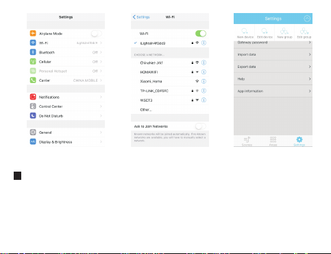
图1 图3图2
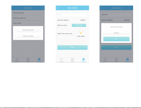
5
Add device
Enter Settings menu/ Add device with 2 methods to add device(picture3,4).
a) Add device by QRCode scanning. Each of device has one QRCode.
Usercan scan QRCode to add device in application(Picture5).Save the
scanned device and check it by Testing button(Picture6).
2
Page 5
Pic ture 4 Pic ture 5 Pic ture 6
Attention:
The device and gateway has to be power on while test button is pressed, but
the device can be power off while scanning QRcode to add device. And the
gateway has to be power on when enter Add device or Add group menu.
b) Add device by pairing. The following are steps to add device by pairing mode
1.First input the device name and select correct device type.
3
Page 6

Pic ture 7 P ict ure 8 P ict ure 9
2.Activate the device pairing mode by power on device (some device will be
on pairing mode in 5 seconds after power on). Or user also can activate
pairing mode by press the key of device.
3.Save the device while device is on pairing mode (The pairing command will
be sent to device while save button is pressed)(Picture7, 8).
Attention:
a. The device type on Add device menu has to be thesame with device!
4
Page 7
Pic ture 10 Pic ture 11 Pic ture 21
b. The following is the definition to activate pairing mode for different device.
LED Driver
6
Scenes
6.1
Add scenes
Product
Activate pairing mode 5 seconds
automatically after power on
Yes
Activate pairing mode 15 seconds by
key
No
5
Page 8

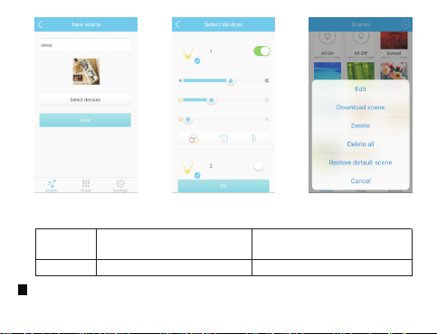
Press to Scene menu. The application can support scene based on
settings in advance . So user can click one scene to reach different status
fordifferent devices.
Press to add new scene, then input the scene name and select devices
and their status( Picture 9).
Click to select the device and its status in this scene.
Example: create one scene with Sleep name and select all Color temperature
light with the color you liked on select devices menu. Click save, then the
Sleep scene is created. User can click the Sleep scene to change all Color
temperature light with the color you selected.(Picture10,11).
Edit scenes
6.2
User can download scene, edit delete scene by long press the scene
(Picture12).
Attention:
The scene and area settings data will be replaced after database
synchronization from another client
7
Area
Add area
7.1
Click to area menu. And click to add new area(Picture13,14)
Input the area name and select devices for this area.
6
Page 9

Area Sub Menu
7.2
Click one area can enter the sub menu and all different device can be listed.
User can control each of device in this area(Picture15).
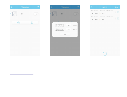
User can move the slider to change color or brightness.
The lights have to bound with daylight sensor for daylight sensor control. The
following is the operation steps.(Picture16,17)
Pic ture 13 Pic ture 14 Pic ture 15
7
Page 10
Pic ture 16 Pic ture 17 Pic ture 18
Attention:
Please binding the device before control the daylight sensor.See chapter 9.3
Binding settings.
a).Power on lights. Bind the light or group in Settings/Binding settings menu.
b).Change the lights brightness to favorite luminance(User can use
illuminometer to get favorite luminance).
8
Page 11
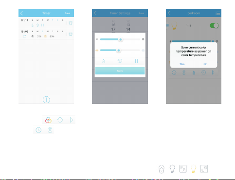
Pic ture 19 Pic ture 20 Pic ture 21
The part can set different effect, interval and run or stop.
Click to enter Timer or delay menu. Under this menu, user can set the
timer or delay and different status while timeout (Picture18,19,20).
User can store the power on color for Color temperature light(Picture21).
User select different type device by the following icons (Picture22).
9
Page 12

Pic ture 22 Pic ture 23 Pic ture 24
Edit area
7.3
User can long press the area button on area menu to edit area or delete area
(Picture23).
8
Add group/Edit group
User can put the same type devices in one group. So all same type
devices in this group can be controlled at same time.(Picture24,25)
Attention: The devices must power on while group setting is saved.
10
Page 13
Pic ture 25 Pic ture 26 Pic ture 27
9
Settings
Click to enter settings menu.
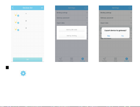
Import data/Export data
9.1
All devices , scene and area are stored on client as database. Please back up
your database after all devices, scene and area adding done.
Apps support database synchronization between 2 clients(Picture26,27,28).
a. Import or export database from SD card or to SD card. (Android)
11
Page 14

Pic ture 28 Pic ture 29 Pic ture 30
b. Import database from another mobile, MID or PC by LAN
Attention: Clients can not synchronize database on iLightsInxxxxxx router
c. Import or export database from gateway.
Network settings
9.2
The gateway also can join another WiFi router for remote control.
Attention: The gateway will recover the default settings after the setting is
failed with wrong SSID, encryption type or password.
12
Page 15
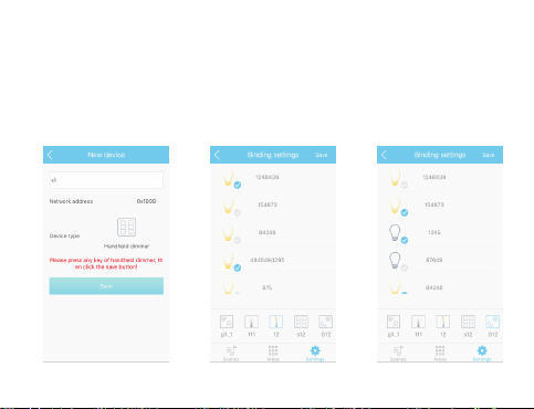
9.3
Binding settings(Picture29,30,31,32,33)
a).Open Add device, select Add by QRcode, Scan the QRcode back of touch
dimmer.
b).Input name and save. Then the touch dimmer has to bound with lights before
light control.
c).Handheld dimmer has to press any key before Click Save.
d).User can bind the remote control, handheld dimmer and sensor with lights.
Pic ture 31 Pic ture 32 Pic ture 33
13
Page 16

Adapter supply:
Model:AEK6W-050100
Input:100-240V 50/60Hz 150mA Max
Output:5V,1A
FCC Caution:
This device complies with part 15 of the FCC Rules.Operation is subject to
the following two conditions:(1) this device may not cause harmful
interference, and (2) this device must accept any interference received,
including interference that may cause undesired operation.
Changes or modifications not expressly approved by the party responsible for
compliance could void the user's authority to operate the equipment.
NOTE: This equipment has been tested and found to comply with the limits for
a Class B digital device, pursuant to Part 15 of the FCC Rules. These limits are
designed to provide reasonable protection against harmful interference in a
residential installation. This equipment generates, uses and can radiate radio
frequency energy and, if not installed and used in accordance with the
instructions, may cause harmful interference to radio communications.
However, there is no guarantee that interference will not occur in a particular
installation.
If this equipment does cause harmful interference to radio or television
reception,which can be determined by turning the equipment off and on, the
user is encouraged to try to correct the interference by one or more of the
following measures:
– Reorient or relocate the receiving antenna.
13
Page 17

-- Increase the separation between the equipment and receiver.
-- Connect the equipment into an outlet on a circuit dif
ferent from that to which
the receiver is connected.
-- Consult the dealer or an experienced radio/TV technician for help.
To maintain compliance with FCC’s RF Exposure guidelines, This equipment
should be installed and operated with minimum distance between 20cm the
radiator your body: Use only the supplied antenna.
FCC ID: 2AJ7E-HGW501
13
Page 18

1
2
3
4
5
9
6
10
7
11
8
12
 Loading...