

Page 1

Hz
Installation, Operation, and
Maintenance Manual
GRP Series
Version 05/2019- No. 00507610.02
60
Page 2

Content
1.2. Preface .............................................................................................................................................................03
1.3. Proper use ........................................................................................................................................................03
1.4. Copyright ..........................................................................................................................................................03
1.5. Technical terms ................................................................................................................................................03
2. Safety .................................................................................................................................03
2.1. Instructions and safety information .................................................................................................................. 03
2.2. General safety ..................................................................................................................................................04
2.3. Operating personnel ......................................................................................................................................... 04
2.4. Electrical work ..................................................................................................................................................04
2.5. Operating procedure ......................................................................................................................................... 05
2.6. Safety and control devices ...............................................................................................................................05
2.7. Operation in an explosive atmosphere ............................................................................................................. 05
2.8. Sound Safety ....................................................................................................................................................05
2.9. Pumped fluids .................................................................................................................................................. 05
2.10. Danger due to spark generation .....................................................................................................................05
3. General description .......................................................................................................... 06
3.1. Application ........................................................................................................................................................ 06
3.2. Types of use .....................................................................................................................................................06
3.3. Construction .....................................................................................................................................................06
4. Package, Transport, Storage ...........................................................................................09
4.1. Delivery ............................................................................................................................................................. 09
4.2. Transport ........................................................................................................................................................... 09
4.3. Storage .............................................................................................................................................................09
4.4. Returning to the supplier ................................................................................................................................. 09
5. Installation and initial commissioning ...........................................................................10
5.1. General .............................................................................................................................................................10
5.2. Installation ........................................................................................................................................................11
5.3. Use of chains .................................................................................................................................................... 12
5.4. Initial operation .................................................................................................................................................12
5.5. Preparatory work ..............................................................................................................................................13
5.6. Electrical ..........................................................................................................................................................13
5.7. Direction of rotation .......................................................................................................................................... 14
5.8. Motor protection ............................................................................................................................................... 15
5.9. Variable Frequency Drives ................................................................................................................................15
5.10. Types of startups ............................................................................................................................................15
6. Maintenance .....................................................................................................................16
6.1. General .............................................................................................................................................................16
6.2 Maintenance intervals .......................................................................................................................................16
6.3. Maintenance tasks ...........................................................................................................................................17
6.4. Seal chamber .................................................................................................................................................... 18
7. Repairs ............................................................................................................................... 18
7.1. General .............................................................................................................................................................18
7.2. Changing the impeller ....................................................................................................................................... 18
7.3 Spare Parts ........................................................................................................................................................19
8. Shutdown ..........................................................................................................................19
8.1. Temporary shutdown ........................................................................................................................................ 19
8.2. Final shutdown / storage ..................................................................................................................................19
8.3. Restarting after an extended period of storage ................................................................................................ 19
9. Troubleshooting ...............................................................................................................19
10. Connection of pumps and mixers ................................................................................. 22
02 | English
Page 3

1.2. Preface
Dear Customer,
Thank you for choosing HOMA Pump Technology. You
have purchased a product which has been manufactured
to the latest technical standards. Read this operating and
maintenance manual carefully before first use, in order
to ensure the product is used safely. The documentation
contains all the necessary specifications for the product,
allowing you to use it properly. In addition, you will also
find information on how to recognize potential dangers,
reduce repair costs and downtime, and increase the reliability and working life of the product.
All safety requirements and specific manufacturer’s requirements must be fulfilled before the product is put
into operation. This operating and maintenance manual
supplements any existing national regulations on industrial safety and accident prevention. This manual must also
be accessible to personnel at all times and also be made
available where the product is used.
1.3. Proper use
In the event of improper use, there is a danger to life for
the user as well as for third parties. Additionally, the product and/or attachments may be damaged or destroyed.
It is important to ensure that the product is only operated in good condition and as intended. To do so, follow
the operating instructions. The pumps can be used in the
range specified by the manufacturer in accordance with
the current HOP.SEL version. Please note that the offered
pumps may only be used in the defined field of application. Operating the pump outside the application range
can lead to operational problems or significant damage to
the unit.
Please note that the surfaces of the product become very
hot!
“transportable” installation type
With this installation type the product is equipped with a
pedestal. It can be installed and operated at any location.
Please observe the values for the maximum submersion
depth and the minimum water coverage, and remember
that the surfaces of the product become very hot.
“S1” operating mode (continuous operation)
At the rated load, a constant temperature is reached that
does not increase even in prolonged operation. The operating equipment can operate uninterruptedly at the rated
load without exceeding the maximum permissible temperature.
Operating mode “S3“ (intermittent operation):
For this operating mode, after the abbreviation, the percent duty cycle is displayed, as well as the cycle duration
if it is greater than 10 minutes. For example: S3 40% 60
minutes means the pump can operate continuously for
40% (24 minutes) of one hour, and must then pause for
36 minutes.
Low Level Lockout
The low level lockout is designed to automatically shut
down the product if the water level falls below the minimum water coverage value of the product. This is made
possible by installing a float switch.
Level control
The level control is designed to switch the product on or
off depending on the water level. This is made possible by
installing a float switch.
1.4. Copyright
This operation and maintenance manual has been copyrighted by the manufacturer. This operation and maintenance handbook is intended for use by assembly, operating and maintenance personnel. It contains technical
specifications and diagrams which may not be reproduced
or distributed, either completely or in part, or used for any
other purpose without the expressed consent of the manufacturer.
1.5. Technical terms
Various technical terms are used in this operating and
maintenance manual.
Dry run
The product is running at full speed, however, there is no
liquid to be pumped. A dry run is to be strictly avoided. If
necessary, a safety device must be installed.
“wet” installation type
This installation type requires the product to be immersed
in the pumped fluid. It is completely surrounded by the
pumped fluid. Please observe the values for the maximum
submersion depth and the minimum water coverage.
“dry” installation type
In this installation type, the product is installed dry, i.e. the
pumped fluid is delivered to and discharged via a pipeline
system. The product is not immersed in the pumped fluid.
2. Safety
This chapter lists all the generally applicable safety instructions and technical information. Additionally, other
chapters contain specific safety instructions and technical information. All instructions and information must be
observed and followed during the various phases of the
product‘s lifecycle (installation, operation, maintenance,
transport etc.). The operator is responsible for ensuring
that personnel follow these instructions and guidelines.
2.1. Instructions and safety information
This manual uses instructions and safety information for
preventing injury and damage to property.
To make this clear for the personnel, the instructions and
safety information are distinguished as follows:
Each safety instruction begins with one of the following
signal words:
Danger: Serious or fatal injuries can occur!
Warning: Serious injuries can occur!
Caution: Injuries can occur!
Caution (Instruction without symbol): Serious damage
to property can occur, including irreparable damage!
English | 03
Page 4
Safety instructions begin with a signal word and description of the hazard, followed by the hazard source and
potential consequences, and end with information on
preventing it.
2.2. General safety
• Never work alone when installing or removing the
product.
• The machine must always be switched off before
any work is performed on it (assembly, dismantling,
maintenance, installation). The machine must be disconnected from the electrical system and secured
against being switched on again. All rotating parts
must be at a standstill.
• The operator should inform his/her superior immediately should any defects or irregularities occur.
• It is of vital importance that the system is shut down
immediately by the operator if any problems arise
which may endanger safety of personnel. Problems
of this kind include:
• Failure of the safety and/or control devices
• Damage to critical parts
• Damage to electric installations, cables and
insulation.
• Tools and other objects should be kept in a place
reserved for them so that they can be found quickly.
• Sufficient ventilation must be provided in enclosed
rooms.
• When welding or working with electronic devices,
ensure that there is no danger of explosion.
• Only use fastening devices which are legally defined
as such and officially approved.
• The fastening devices should be suitable for the
conditions of use (weather, hooking system, load,
etc). If these are separated from the machine after
use, they should be expressly marked as fastening
devices. Otherwise they should be carefully stored.
• Mobile working equipment for lifting loads should
be used in a manner that ensures the stability of the
working apparatus during operation.
• When using mobile working equipment for lifting
non guided loads, measures should be taken to avoid
tipping and sliding etc.
• Measures should be taken that no person is ever
directly beneath a suspended load. Furthermore,
it is also prohibited to move suspended loads over
workplaces where people are present.
• If mobile working equipment is used for lifting loads,
a second person should be present to coordinate the
procedure if needed (for example if the operator‘s
field of vision is blocked).
• The load to be lifted must be transported in such a
manner that nobody can be injured in the case of a
power cut. Additionally, when working outdoors,
such procedures must be interrupted immediately if
weather conditions worsen.
These instructions must be strictly observed.
Non-observance can result in injury or serious
damage to property. This product may contain chemicals known to the State of California to cause cancer
and birth defects or other reproductive harm.
www.p65warnings.ca.gov
2.3. Operating personnel
All personnel who work on or with the product must be
qualified for such work; electrical work, for example may
only be carried out by a qualified electrician. The entire
personnel must be of age. Operating and maintenance
personnel must also work according to local accident prevention regulations. It must be ensured that personnel
have read and understood the instructions in this operating and maintenance handbook; if necessary this manual
must be ordered from the manufacturer in the required
language.
2.4. Electrical work
Our electrical products are operated with alternating or industrial high-voltage current. The local regulations (e.g. 2017 NEC) must be adhered
to. The technical specifications must be strictly adhered to. If the machine has been switched off by a
protective device, it must not be switched on again until
the error has been corrected.
Beware of electrical current!
Incorrectly performed electrical work can result in
fatal injury! This work may only be carried out by a
qualified electrician.
Beware of Moisture!
Moisture penetrating into cables can damage them
and render them useless. Furthermore, water can
penetrate into the terminal compartment or motor
and cause damage to the terminals or the winding.
Never immerse cable ends in the pumped fluid or
other liquids.
2.4.1. Electrical connection
When the machine is connected to the electrical control
panel, especially when electronic devices such as soft
startup control or frequency drives are used, the relay
manufacturer‘s specifications must be followed in order
to conform to EMC. Special separate shielding measures
e.g. special cables may be necessary for the power supply
and control cables.
The connections may only be made if the equipment
meets NEC standards. Mobile radio equipment may
cause malfunctions.
Beware of electromagnetic radiation!
Electromagnetic radiation can pose a fatal risk for
people with pacemakers. Put up appropriate signs
and make sure anyone affected is aware of the
danger.
2.4.2. Ground connection
Our products (machine including protective devices and
operating position, auxiliary hoisting gear) must always be
grounded. If there is a possibility that people can come
into contact with the machine and the pumped liquid (e.g.
at construction sites), the grounded connection must be
additionally equipped with a fault current protection device. The electrical motors conform to motor protection
class IP 68 in accordance with the valid norms.
04 | English
Page 5
2.5. Operating procedure
When operating the product, always follow the locally
applicable laws and regulations for work safety, accident
prevention and handling electrical machinery. To help to
ensure safe working practice, the responsibilities of employees should be clearly set out by the owner. All personnel are responsible for ensuring that regulations are
observed. Certain parts such as the rotor and impeller rotate during operation in order to pump the fluid. Certain
materials can cause very sharp edges on these parts.
Beware of rotating parts!
The moving parts can crush and sever limbs. Never
reach into the pump unit or the moving parts during
operation. Switch off the machine and let the moving
parts come to a rest before maintenance or repair
work!
2.9. Pumped fluids
Each pumped fluid differs in regard to composition, corrosiveness, abrasiveness, TS content and many other
aspects. Generally, our products can be used for many
applications. For more precise details, see chapter 3, the
machine data sheet and the order confirmation. It should
be remembered that if the density, viscosity or the general
composition change, this can also alter many parameters
of the product. Different materials and impeller shapes
are required for different pumped fluids. The more exact
your specifications on your order, the more exactly we can
modify our product to meet your requirements.
If the area of application and/or the pumped fluid change,
we will be happy to offer supportive advice.
When switching the product into another pumped fluid,
observe the following points:
2.6. Safety and control devices
Our products are equipped with various safety and control
devices. These include, for example moisture sensors and
temperature sensors. These devices must never be dismantled or disabled. Equipment such as thermo sensors,
float switches, etc. must be checked by an electrician
for proper functioning before start-up. Please remember
equipment such as PT100 temperature monitors or float
switches require the use of a HOMA GO switch for connection. Please contact your HOMA distributor for information.Personnel must be informed of the installations
used and how they work.
Caution!
Never operate the machine if the safety and monitoring devices have been removed or damage, or if they
do not work.
2.7. Operation in an explosive atmosphere
Products marked as FM approved for suitable operation in
explosive atmosphere, are designed for Class I, Division
1, Groups C and D and Temperature class T4. The permitted ambient temperature is between -4°F and 104°F.
The enclosures protection class is IP68. The products
must meet certain guidelines for this type of use. Certain
rules of conduct and guidelines must be adhered to by
the operator as well. Products that have been approved
for operation in an explosive atmosphere are marked as
explosion-proof rated by FM. In addition, an “FM” symbol
must be included on the name plate!
2.8. Sound Safety
Depending on the size and capacity (kW), the products
produce a sound pressure of up to110 dB. The actual
sound pressure, however, depends on several factors.
These include, for example, the installation type (wet, dry,
transportable), fastening of accessories (e.g. suspension
unit) and pipeline, operating site, immersion depth, etc.
Once the product has been installed, we recommend that
the operator make additional measurements under all operating conditions.
• Products which have been operated in sewage or
waste water must be thoroughly cleaned with pure
water or drinking water before use.
• Products which have pumped fluids which are hazardous to health must always be decontaminated
before changing to a new fluid. Also clarify whether
the product may be used in a different pumped fluid.
• With products which have been operated with a
lubricant or cooling fluid (such as oil), this can escape
into the pumped fluid if the mechanical shaft seal is
defective.
Danger - explosive fluids!
It is absolutely prohibited to pump explosive liquids
(e.g. gasoline, kerosene, etc.). The products are not
designed for these liquids!
2.10. Danger due to spark generation
Mechanically generated sparks can ignite flammable gases and condensates. According to EN1127-1 Para.6.4.4,
sparks must also be excluded for category 2 in normal
operation. In normal operation no spark generation is possible due to fluid covering (medium covering of the pump
hydraulic).The ingress or suction of foreign bodies (stones,
pieces of metal, etc.) through the suction nozzles into the
pump hydraulic is not possible in an expected case of malfunction in which the enclosure fails as the pump cannot
suck up pumping medium nor its containing solids.
In the ventilated shaft, the explosion-protected submersible motor pumps are drained via a drain system with
two guide tubes of galvanized steel, between their guide
claws of grey cast iron that guide into the automatic coupling arrangement.
The guide velocity, with max 0.1 m/s (10cm/s) is so low
that no sparks can be generated even in the most disadvantaged conditions. In the first installation, the guide
claws of the drain arrangement should be lubricated with
ball bearing grease in order to supredd heat and spark
generation in the most disadvantaged case.
Caution: Wear ear protectors! In accordance with
the laws in effect, guidelines, standards and regulations, ear protection must be worn if the sound pressure is greater than 85 dB (A)! The operator is responsible for ensuring that this is observed!
English | 05
Page 6
3. General description
3.1. Application
Waste water disposal with small pipework cross-sections,
good delivery heads at relatively low flow rates and pressure drainage systems in areas with difficult topography.
GRP pumps shred solids in the pumped medium in next
to no time, so plastic pipework with a cross-section as
small as 2” can be used.
This significantly reduces the cost of materials and laying
the waste water systems. If the pumped medium contains corrosive substances, the corrosion resistance of
the materials used must be observed. For such applications, versions made partly or entirely of highly resistant
materials (stainless steel) are also available
3.3. Construction
The major pump components consist of the motor housing, volute, and impeller.
According to the type of installation and motor cooling, the machine must be submerged in pumped liquid at least up to the top edge of the pump or motor
housing.
For continuous operation (S1) without a cooling jacket, the motor housing must be completely submerged.
The temperature of the pumped medium may be up to
104°F or up to 140°F for a short period. The maximum
density of the medium is 0.03757 lbs/in³ and the pH may
be from 6 – 11.
Stainless steel variants can be used at a pH of 4 - 14.
However, the pH alone only serves as a guideline. Consult
factory for assistance with chemically aggressive liquids.
Depending on the composition, it may be necessary to
use special sealing materials.
3.2. Types of use
The motors are designed for continuous operation (S1),
maximum 15 starts per hour.
The hydraulic is designed for permanent operation, e.g.
supply of industrial water.
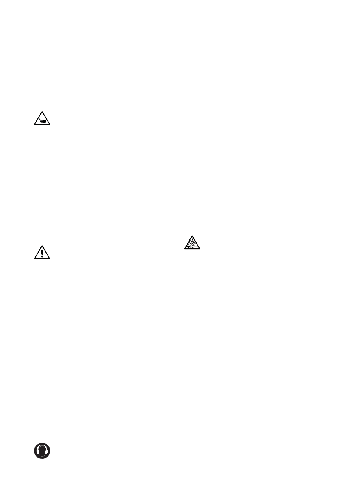
No. Description
1 Lifting handle
2 Name plate
3 Motor housing
4 Cable inlet
5 Discharge
6 Suction piece with cutting system
7 Volute
06 | English
No. Description
1 Lifting handle
2 Motor housing
3 Cable inlet
4 Discharge
5 Name plate
6 Volute
7 Suction cover with feet
Page 7
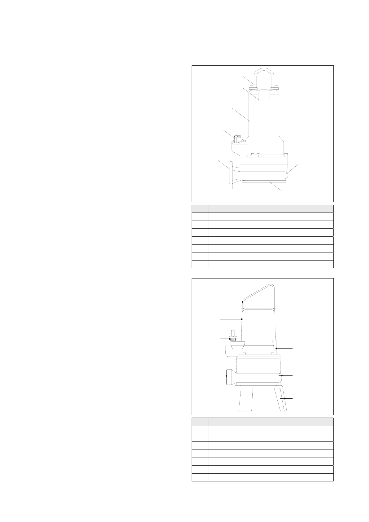
No. Description
1 Lifting handle
2 Motor housing
3 Name plate
4 Discharge
5 Cable inlet
6 Volute
7 Suction cover with feet
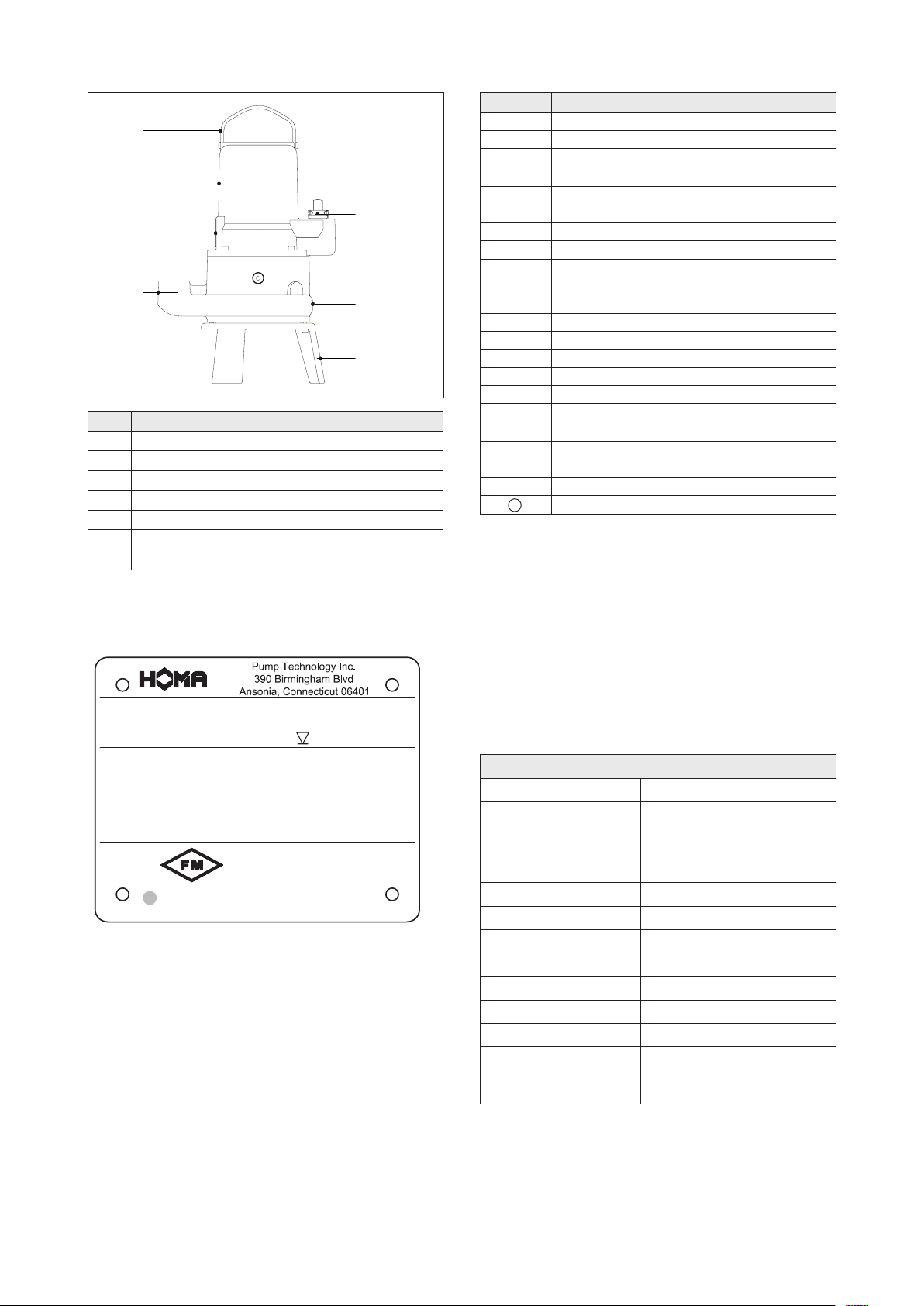
3.3.1. Type label
Pump:
Cont. Duty: 40° C amb.
Hmax:
Motor:
U: V
Hz
a
Cl.I,DIV.1,GR.CD
Hmin:
ft
P:
~
Flow max.:
I
:
HP
Nema code:
Wiring Diagram:
Operating Mode:
APPROVED
21
Thermally protected! See manual for cord replacement!
Do not remove covers while circuits are alive!
Sn:
Date:
cos
Ins. cl.:
φ:
IP 68
gpm
lbs
A
ft
rpm
No. Description
a
b
c
d
e
f
g
h
i
j
k
l
m
m a
n
o
p
q
r
s
t
21
3.3.2. Motor
The pump motor consists of the stator and shaft with
impeller assembly. The cable for the power supply is designed for maximum mechanical performance in accordance with the characteristic or pump name plate. Both
the cable entries and the cable are water-pressure tight to
the depth provided on the name plate. The shaft bearing
assembly is supported via robust, maintenance-free and
permanently lubricated roller bearings. All motors can also
be delivered in an explosion-proof version in accordance
with FM Class I, Division 1, Groups C & D.
General motor data
Service factor 1.15
Operating mode S1
Operating mode at 208V
only if a 208Vmotor was
ordered S3 42% 60min
Max. liquid temperature 35°C / 95°F
Insulation class H (180°C / 356°F)
Degree of protection IP68
Cable length 32 ft
Rotor shaft seal Silicon-carbide / Silicon-carbide
Rotor shaft seal GRP10-21 Silicon-carbide / Buna N
Mechanical shaft seal Silicon-carbide / Silicon-carbide
Bearing One grooved ball bearing (above),
Pump name
Serial number
Flow max
Hmax (Head max)
Hmin (Head min)
Submersion depth
Weight
Motor name
Date of manufacture
Voltage
Motor Power
Nominal current
Frequency
Phase
Motor speed
Cos phi
Temperature class
Nema Code Letter
Wiring diagram
Insulation class
Operating mode
Comments
double-row type angular ball bearing
(below)
English | 07
Page 8

3.3.3. Monitoring Equipment
The unit is equipped with various types of monitoring-safety equipment. The following table shows an overview of
the options available. The options may vary depending on
the size of the pressure outlet
Motortype Motorversion
…/C Temperature monitoring in the winding, Oil chamber
seal conditions sensor
...FM Temperature monitoring in the winding, Explosion
proof
.../C FM Temperature monitoring in the winding, Oil chamber
seal conditions sensor and motor connecting chamber,
Explosion proof
ET... Jacket cooled motor, thermal monitoring of winding,
monitoring of oil chamber seal
ET... FM Jacket cooled motor, thermal monitoring of winding,
monitoring of oil chamber seal, explosion-proof
Temperature Sensor
All pumps are equipped with a temperature sensor in
each motor winding. In standard pumps, the connections
for the temperature sensor are fed via the power cable to
the outside and are to be connected in the electric control box using the T1 and T3 power cable endings in such
a way that the motor automatically restarts after it has
cooled down.
Instead of the standard sensor, the explosion-proof versions are equipped with a temperature sensor assembly
that has a higher activation temperature. This is to be connected via the power cable endings T1 and T2 in such
a way that after activation, a manual reset is necessary
to restart the pump. The temperature sensor assembly
must be connected in the control panel so that it switches
off when it overheats.
Switch-off temperature of the sensors:
Motor
Frame
T 140°C / 284°F 140°C / 284°F 80°C /
Stator Winding
T1+T3
Regulator
Stator
Winding FM
T1+T2 Limiter
Lower
Bearing
Upper
Bearing
n/a
176°F
ET 125°C / 257°F 125°C / 257°F n/a n/a
Seal monitoring:
In case of a leak in the lower shaft seal, water enters
the oil chamber and changes the resistance of the oil.
The conductivity of the oil is monitored via one sensor to
ground. In the motor housing, another sensor monitors for
the resisitance to ground in case of water intrusion. The
sensors are to be connected via 2 cables (consult wiring
diagram) from the pump connection cables in the control
panel to a monitor galvanically separated from the probe
circuit. The response sensitivity should be adjustable from
0-100 kΩ, the standard setting being 50 kΩ. For external
seal probes an electrode relay with an intrinsically safe
circuit is to be chosen.
FM pumps: The sensors are connected via 2 cables
(labelled S1 and S2) of the pump connector cable in the
switching system to an evaluation device with an electrically isolated special circuit.
3.3.4. Sealing / Seal Housing
Sealing is accomplished in GRP24 and larger models by
two silicon carbide mechanical seals in a tandem arrangement, acting independently from each other. In smaller
models, sealing is accomplished by a silicon carbide lower
mechanical seal, and a nitrile rubber (Buna N) upper lip
seal. The seal housing is situated between the motor and
the pump housing. It consists of the bearing housing and
the pressure cover, which together form the sealing cavity with containing white mineral oil. Monitoring possibilities are available using the inspection plug on the bearing
housing and optional electronic monitoring.
3.3.5. Jacketed Pump Option
The cooling jacket has been supplied based upon the
specified operating conditions of this application. It is important this jacket is functioning properly, or the internal
motor components could become damaged. Several cooling configurations are available depending upon customer
preference and system requirements.
You must know what configuration of cooling system is
to be used with the pump prior to installation. In some
cases, field test results may indicate a change of cooling
method is required. Consult factory for necessary changes to the pump.
COOLING REQUIREMENTS
Standard Media Cooled –
This construction does not require any external piping and
it is completely self-contained. This design is suitable for
the routine collection system application. No pump modifications are required.
3.3.7. Volute
The volute depending on the model, will have one of several discharge connections. Please consult an available
drawing or your local HOMA distributor if you need help
identifying the discharge connection on your pump.
3.3.8. Impeller
The impeller is fastened directly to the motor shaft and
driven by it. GRP pumps are only available with an open
multi-channel impeller.
3.3.9. Cutter system
The cutter system includes a fixed cutting ring and a cutter head which is mounted on the motor shaft. Thereby
the cutter head turns with motor rotation speed and cut all
solids in the sewage. Both parts consist of stainless steel
hardened to HRC55.
08 | English
Page 9

4. Package, Transport, Storage
4.1. Delivery
On arrival, the delivered items must be inspected for damage and a check made that all parts are present. If any
parts are damaged or missing, the transport company or
the manufacturer must be informed on the day of delivery.
Any claim made at a later date will be deemed invalid.
Damage to parts must be noted on the delivery or freight
documentation.
4.2. Transport
Only the appropriate and approved fastening devices,
transportation means and lifting equipment may be used.
These must have sufficient load bearing capacity to ensure that the product can be transported safety. If chains
are used they must be secured against slipping.
The personnel must be qualified for the tasks and must
follow all applicable national safety regulations during
the work. The product is delivered by the manufacturer/
shipping agency in suitable packaging. This normally precludes the possibility of damage occurring during transport and storage.
Beware of electrical current!
Damaged power supply cables can cause fatal injury! Defective cables must be replaced by a qualified
electrician immediately.
Beware of moisture!
Moisture penetrating cables can damage them and
render them useless. Therefore, never immerse cable ends in the pumped fluid or other liquids.
• The machine must be protected from direct sunlight,
heat, dust, and frost. Heat and frost can cause considerable damage to impellers, rotors and coatings.
• The impeller must be turned at monthly intervals.
This prevents the bearing from locking and the film
of lubricant on the mechanical shaft seal is renewed.
This also prevents the gear pinions (if present on the
product) from becoming fixed as they turn and also
renews the lubricating film on the gear pinions (preventing rust film deposits).
Beware of sharp edges!
Sharp edges can form on rotors and impellers.
There is a risk of injuries. Wear protective gloves.
Never lift the pump by its power cable! Jacketed
pump should not be lifted or supported by the jacket.
Damage to sealing O Rings may result.
4.3. Storage
Newly supplied products are prepared that they can be
stored for 1 year. The product should be cleaned thoroughly before interim storage.
The following should be taken into consideration for
storage:
• Place the product on a firm surface and secure it
against falling over. Submersible mixers and auxiliary lifting devices should be stored horizontally,
submersible sewage pumps and submersible motor
pumps should be stored horizontally or vertically. It
should be ensured that they cannot bend if stored
horizontally.
Falling Hazard!
Never leave the pump unsecured!
• The product has to be stored in a place free from
vibrations and agitation to avoid damage to the ball
bearings.
• The device should be stored in a dry place without
temperature fluctuation.
• The product may not be stored in rooms where welding work is conducted as the resulting gases and radiation can damage the elastomer parts and coatings.
• Be careful to not remove or damage the corrosion
resistant coatings.
• Any suction or pressure connections on products
should be closed tightly before storage to prevent
impurities.
• The power supply cables should be protected against
kinking, damage and moisture.
• The cable will wick water into the pump if it is not protected properly. Power cable lead should be covered
with shrink tubing or suitable sealing material during
storage.
• If the product has been stored for longer than six
months it should be cleaned of impurities such as
dust and oil deposits before start-up. Rotors and impellers should be checked for smooth running, housing coating and damage.
• After remaining in storage for longer than one year,
it is necessary to change the oil in the seal chamber.
This is necessary even if the pump has never been
run, due to natural deterioration of mineral oil.
Before start-up, the filling levels (oil, cooling fluid
etc.) of the individual products should be checked and
topped up if required. Please refer to the machine data
sheet for specifications on filling. Damaged coatings
should be repaired immediately. Only a coating that
is completely intact fulfills the criteria for intended
usage!
If these rules are observed, your product can be stored
for a longer period. Please remember that elastomer parts
and coatings become brittle naturally. If the product is
to be stored for longer than 6 months, we recommend
checking these parts and replacing them as necessary.
Please consult the manufacturer.
4.4. Returning to the supplier
Products which are delivered to the factory must be clean
and correctly packaged. In this context, clean means
that impurities have been removed and decontaminated if it has been used with materials which are hazardous to health. The packaging must protect the product
against damage. Please contact the manufacturer before
returning!
English | 09
Page 10

5. Installation and initial commissioning
5.1. General
To avoid damage to the lifting unit during installation and
operation, the following points must be observed:
• The installation work must be performed by qualified
personnel, in compliance with safety regulations.
• The pump must be inspected for damage prior to installation.
• For level controls, pay attention to the minimum water coverage.
• Air bubbles in the volute and pipework must be avoided (by suitable ventilation devices or a slight incline
of the pump).
• Protect the pump from frost.
• The lifting device must have a maximum load capaci-
ty which is greater than the weight of the pump with
attachments and cable.
• The power lines of the pump must be laid in such a
way, that a safe operation and easy assembly/disassembly is ensured.
• The power lines must be fixed properly in the operating room to prevent the cable from hanging loosely.
Depending on the cable length and weight, a cable
holder must be attached every 2-3 m.
• The foundation/structure must have sufficient
strength for secure and functionally correct fastening
of the pump. The operator is responsible for this.
• Verify low level lockout is functioning.
• Use baffles for the inlet. This prevents air entry into
the pumping medium, which can lead to unfavorable
operating conditions and result in increased wear.
• Do not install more than one check valve into any piping system or problems will occur.
No. Description
1 Pipe
2 Coupling system
3 Wet well
4 Inlet
5 Baffle plate
6 min. liquid level
7 Pump
External Seal Probe Installation Procedure
Mechanical Seal Leak Detection probe has been
shipped loose to protect from shipping damage.
Please follow this procedure to install the probe.
1. Lay pump on its side with the plug on the seal chamber facing upwards as indicated.
2. Unscrew the plug with the proper wrench, taking
care not to damage the sealing surface.
3. Verify that seal chamber oil level is within ¼” of the
indicated value. Measurement is from oil level to the
top of hole. See IOM Manual for seal chamber oil volume, if required.
4. Remove the new sealing gasket from package and
install it onto the seal probe plug.
5. Install the seal probe with gasket into the opening,
taking care not to damage the cable. Then tighten the
seal probe with the proper wrench until snug. Do not
overtighten. Once tight, verify the seal gasket is properly seated and the cable is not pinched or twisted.
NOTE: At installation of the seal probe be careful not
to bind the seal probe cord as it is being installed into
the pump.
6. Lift pump into a vertical position and inspect for any
leaks.
7. Secure seal probe cable to pump body and power cable with tyraps before installing pump.
10 | English
Page 11

5.2. Installation
Risk of falling!
When installing the pump and accessories, work is
carried out directly on the water‘s edge! Carelessness or wearing the wrong shoes can lead to falling.
This is life threatening! Take all safety precautions to
prevent this.
Torque Values
PUMP
Installation
Bolts
Anchors
SIZE TORQUE
Autocoupling 8 M16X60mm 146 Nm / 108 ft lb
4 M16 100 Nm / 74 ft lb
Ring stand 4 M16x25mm 146 Nm / 108 ft lb
Notes:
1. Flange bolts must be tightened in cross pattern to
avoid damage to the raised face flanges.
2. Standard flange bolts are 316SS
3. Standard anchors are plated steel.
4. Autocoupling systems include qty. 4 M12 anchors for
the upper bracket. Torque to 51 Nm / 38 ft lb.
5. Anchor bolt holes should be drilled to the actual diameter of the anchor (M12 anchor requires 12mm
diameter hole).
Submerged installation on ring stand
Attach the ring stand (available as an accessory) with
screws to the pump suction nozzle. 90° connection-elbow or connection loop to the pressure port of the pump,
mount pressure line. Gate valves and check valves may
need to be installed in accordance with local regulations.
The pressure line must be fitted free of tension, when
using a hose, ensure it is laid kink-free.
Secure the pump by the handle with a cable or chain,
and lower it into the pumping medium. Properly position
power cable and chain so they stay above the pump and
cannot enter the pump suction.
guide tubes, using a plumb bob where necessary.
• Check the correct installation dimensions of the
pump(s) (see dimensional drawings in the appendix).
• Drill mounting holes for the guide rail bracket on the
inside edge of the shaft opening. If this is not possible due to the space available, the guide rail bracket
can also be mounted in an offset position with a 90°
folded plate on the underside of the shaft cover. Provisionally fasten the guide rail bracket with 2 screws.
• Align the base elbow to the shaft floor, use a plumb
bob from the pipe bracket - the guide tubes must be
exactly perpendicular! Fasten the base elbow to the
wet well floor using anchor bolts. Ensure that the
base elbow is exactly horizontal! If the wet well floor
is uneven, support the bearing surface accordingly.
• Mount the pressure pipes with fittings free of tension
according to the usual mounting principles.
• Insert both guide rails into the eyelets on the base
elbow and cut to size according to the position of the
guise rail bracket. Partially unscrew the guide rails
bracket, insert them into the guide rails and fasten
the bracket. The guide rails must be positioned with
no play at all, otherwise vibration will occur during operation of the pump.
• Clean the wet well of any solid material (debris,
stones, etc.) before commissioning.
• Mount the guide claw on the pump discharge. For
threaded discharge connections, apply pipe sealant
to the threads for installation and DO NOT OVER
TIGHTEN. DISCHARGE THREADS ARE NOT NPT.
Ensure that the rubber profile seal is correctly seated
in position in the guide claw (as a seal against the
coupling base), so that it will not fall out when lowering the pump. See graphic below
• Attach the chain to the pump handle or lifting lugs.
For model GRP 10-50 series pumps, attach tether
through the large opening of the lifting handle. DO
NOT attach to the small, rear tab. Insert the pump
with the guide rails in the guide claw ears. Lower
the pump into the wet well. If the pump is seated on
the base elbow, it automatically seals itself off to the
pressure line and is ready for operation.
• Hang the end of the retrieval chain from a hook at the
wet well opening.
• Hang the motor connection cable of the pump in the
shaft at an appropriate length, with strain relief. Make
sure that the cables can not be bent or damaged.
Correct
Rubber Ring
Incorrect
Rubber Ring
Wet well installation with automatic coupling system
The following instructions apply to the installation of the
original HOMA Autocoupling system:
• Determine the approximate position of the position
of the base elbow and the upper pipe bracket for the
English | 11
Page 12

Dry Installation
Foundation and Piping Requirements:
General
The following recommendations are basic guidelines
which are intended to outline basic requirements in the
design of the dry pit station. It is essential that a licensed
professional engineer be retained by the owner to design
the station and all support structures.
Foundations
Foundations may consist of any structure heavy enough
to provide permanent rigid support for the pump and inlet
elbow stand. Concrete foundations built up from the solid
ground are the most commonly used. The concrete floor
shall be level. The space required by the inlet stand and
the location of the foundation anchor bolts are shown on
the outline dimension drawing. Foundation bolts are to be
embedded in the concrete.
Suction Piping
Suction piping should be at least as large as the pump
inlet elbow suction. If reducers are utilized they should
be of the conical type. If the liquid source level is below
the volute horizontal centerline, the reducer must be
eccentric and installed with the level side up. If the liquid
level is above the pump volute horizontal centerline, either
eccentric or concentric reducers may be used. Suction
piping should be run as straight as possible. All pipe flange
joints should be gasketed to prevent air from entering the
pipe. High points that may collect vapor are to be avoided.
Isolation valves such as gate valves can be installed in order to facilitate the removal of the pump for maintenance.
Any valve installed in the suction line should be installed
with the stems horizontal.
• Attach the other end to the lifting device.
• Ensure tension on the chain, and then lift the pump in
a slow and controlled manner.
• Gently lower the pump into operating space.
• Lower the pump to the operating point and make
sure that the pump has a secure footing or the coupling system is engaged correctly.
• Remove the chain from the lifting device and secure
it to the safety chain, which is located at the top of
the operating room. This ensures that the chain can
not fall into the operating area and constitute a danger to anyone.
Please note the following diagrams during installation.
Discharge Piping
A check valve and isolation valve shall be installed in the
discharge line. The check valve should be installed between the pump discharge flange and the isolation valve.
If pipe increasers are used on the discharge line, they
should be placed between the check valve and the pump.
The inlet elbow stand allows the pump to be installed in
a stationary position in a dry pit. Place the inlet stand in
position and tighten the anchor nuts.
Lower the pump on to the top flange of the inlet stand.
DO NOT ALLOW SLACK ON THE LIFTING CABLE UNTIL
THE PUMP IS BOLTED DOWN. Make sure the flange bolt
holes align with the mounting holes on the underside of
the volute. Secure the pump to the mounting flange with
the fasteners that are specified in the accessory fastener
selection table below.
5.3. Use of chains
Chains are used to lower a pump in the operating space
or to pull it out. They are not intended to secure a floating
pump. Intended use is as follows:
• Fasten one end of the chain on the handle of the
pump provided for this purpose. If your pump has
two ring bolts as an attachment point, you must use
a double-strand chain. When doing so, the angle of
inclination of the chain strands must be between 0°
and 45°.
No. Description
1 Chain guard
2 Chain
3 Handle
4 Pump
5.4. Initial operation
This chapter contains all the important instructions for operating personnel for the safe commissioning and operation of the machine. The following information must be
strictly adhered to and checked:
• Type of installation
• Operating mode
• Minimum submergence
12 | English
Page 13

After a long downtime, these specifications are also
to be checked and any defects are to be rectified! The
operation and maintenance manual must always be
kept with the machine, or be kept in a designated place
where it is always accessible for all of the operating
personnel.
To avoid injury to persons or damage during operation of
the machine, the following points must be observed:
• The initial operation may only be carried out by qualified and trained personnel accompanied by an authorized HOMA representative following the safety
instructions.
• All staff working on the machine must receive, read,
and understand the instructions.
• Activate all safety devices and emergency stop
switches before initial operation.
• Electrical and mechanical adjustments may only be
performed by professionals.
• This machine is only suitable for use at the specified
operating conditions.
Make sure that all temperature sensors and monitoring
devices, seal chamber probe, are connected and tested
for function.
Risk of electrocution!
Improper use of electricity can be fatal! All pumps
with exposed cable ends must be connected by a
qualified electrician.
All electrical work shall be carried out under the supervision of an authorized, licensed electrician. The present
state adopted edition of the National Electrical Code as
well as all local codes and regulations shall be complied
with.
5.6.1 Verification of power supply
Prior to making any electrical connections or applying
power to the pump, compare the power supply available
at the pump station to the data on the unit‘s nameplate.
Confirm that both voltage and phase match between
pump and control panel.
5.5. Preparatory work
This pump has been designed so that it will operate reliably and for long periods under normal operating conditions. This requires, however, that you comply with all
advice and instructions.
Please check the following points:
• Cable routing - no loops, slightly taut
• Liquid temperature and immersion depth check - see
machine data sheet
• If a hose is used on the discharge side, it should be
flushed before use with fresh water so that no deposits cause blockages
• For wet installation, the wet well must be cleaned
• The pressure and suction side pipe systems are to be
clean and all valves are to be opened.
• If the pump is jacketed with media cooling, the jacket
must be completely bled of air, i.e. it must be completely filled with the medium and there may be no
more air in it. The venting can be done by suitable
ventilation devices in the system, or, if available, by
venting screws at the outlet nozzle.
• Check the accessories, pipe system and suspension
unit for firm and correct fit
• Review the present level control.
• An isolation test and a level control must be carried
out before commissioning.
5.6.2 Power lead wiring
HOMA pumps may be provided with 1 or more cables,
depending on motor horsepower and operating voltage.
Power leads L1, L2, & L3 may be provided as single conductor, or as multiple conductors. Multiple conductor
configurations may use leads from separate cables, or
may use two conductors within one cable. Please refer
to wiring diagram in the appendix for specific connection
details. The pump must be connected electrically through
a motor starter with proper circuit breaker protection in
order to validate warranty. Do not splice cables.
5.6.3 Thermal switch wiring
Pumps are equipped with thermal switches embedded in
the stator windings which are normally closed, automatically resetting switches. Switches will open when the
internal temperature rises above the design temperature,
and will close when the temperature returns to normal.
Thermal switches must be wired to a current regulated
control circuit in accordance with the NEC.
Identify thermal switch leads marked T1 and T2 in the
power or control cable.
The resistance across the leads will be 0.5 Ohms. Thermal leads must be connected to the thermal overload
relay located in the control panel. Thermal switch leads
must be connected to validate warranty.
5.6. Electrical
When installing and selecting electrical lines and when
connecting the motor, the relevant local and NEC regulations must be observed. The motor must be protected by
a motor protection circuit breaker. Connect the motor per
the wiring diagram. Pay attention to the direction of rotation! If rotation is in the wrong direction, the machine will
not perform to specifications. And can be damaged under
adverse circumstances.
Check the operating voltage, and ensure there is uniform
power consumption by all phases in accordance with the
machine data sheet.
Note: All sizes of Class 1, Div. 1 pumps for hazardous
service must have thermal switch leads connected to
a current regulated control circuit in accordance with
NEC.
5.6.4 Seal probe wiring
The mechanical seal leak detector probe utilized in the
pump is a conductive probe which is normally open. The
intrusion of water into the seal chamber completes the
electrical circuit. Control panel provisions will sense this
circuit closure, and will provide indication or alarm functions depending on the panel design.
English | 13
Page 14

Either single or dual wire systems may be provided. Sin-
START
REACTION
ROTOR
REACTION
ATTENTION
The direction of rotation
is correct if the
impeller/propeller rotates
in a clockwise manner
when viewing down from
top of the placed unit
ATTENTION
The start reaction is
counter clockwise
gle wire systems utilize one energizing conductor, and
the pump casing and neutral lead as the ground or return
portion of the circuit. The dual wire systems utilize two
separate conductors for each leg of the circuit.
( ) The standard capacitor kit provided includes:
____________ µf start capacitor
____________ µf run capacitor.
With either system, the seal probe leads must be wired
into a control circuit provided in the control panel. This
control circuit must energize the probe with a regulated
power source, and sense the closed circuit in event of
water intrusion Indication and alarm functions must also
be provided in the control circuit. Please see control panel
wiring diagram for seal probe connection points.
For Hazardous Area Classification Pumps, leak detector circuit must be in conformance with applicable NEC codes and regulations.
5.6.5 Start / Run Capacitors and Relays
All single phase motors require start and run capacitors
along with a start relay to operate. Capacitors and relays
must be sized for the specific motor.
Capacitors are sized based on ideal conditions.
The run capacitor may need to be resized to match the
available field voltage. Each cap kit shipped is supplied
with a wiring diagram and start up procedure.
5.6.6 Single Phase Pump Start-Up Procedure
Run Capacitor sizing can vary depending on the incoming
supply voltage provided. HOMA Single Phase pumps are
provided with Start and Run Capacitor(s) sized for 220230V under load. Frequently, the available line voltage is
considerable different than indicated, and the Run capacitor(s) may need to be resized to match the available field
voltage. The following procedure will allow you to verify
proper operation of your single phase pump, and/or make
necessary changes to you capacitors to correct for your
power supply.
After verifying wiring is in accordance with your pump requirements, start pump and record the following readings
from each of the (3) pump cable leads.
( ) Additional run capacitors have been included for use
in tuning the pump to match available line voltages for
optimum performance.
____________ µf run capacitor
____________ µf run capacitor
____________ µf run capacitor
This form is provided for your use in optimizing the performance and service life of your single phase pumps, and is
applicable to most Capacitor Start/Capacitor Run motors.
Please contact our customer service with any questions
or if you require any additional information or assistance.
5.7. Direction of rotation
Rotation Direction Check
All pumps have the proper rotation direction when connected to a clockwise field of rotation (U, V, W -> L1, L2,
L3). If the pump rotation is backwards, swap two lead and
reconnect. For smaller pumps, the check can be done by
observing the pump’s movement while starting.
To do this, set the pump lightly on the ground in a perpendicular fashion and switch it on briefly. When observing
from above, the pump itself moves slightly in a counter-clockwise direction when rotating in the right direction.
The correct direction of rotation of the pump is achieved
once the pump moves counter-clockwise, since when
viewed from above, the motor starts in a clockwise direction.
Current under load:
U1________Amps,>U2________Amps,>Z2________Amps
U1: (Should be) highest reading
U2: middle reading
Z2: lowest reading
Lead U1 (common) should have the highest current reading. Lead Z2 (start) should have the lowest reading.
If Z2 current draw is greater than the current draw of either U1 or U2, a smaller size Run capacitor (lower microfarad rating) is required to correct the condition. Example:
If a 60 µf Run capacitor was supplied, change to a 50 µf
Run capacitor and check current readings. Typically, only
one step down in capacitor size is required, but in certain
instances 2 steps may be required.
14 | English
For large pumps, the direction can also be determined by
looking through the pump discharge into the volute. Briefly run the motor in order to verify it is running clockwise.
Caution – Rotating Impeller!
Do not touch the rotating impeller or reach into the
volute through the pressure outlets!
Never reach into the volute or touch any rotating
parts during operation. Switch the machine off and
wait until all rotating parts have come to a stop prior
to carrying out maintenance and repair work!
Page 15

It is also possible to check the direction of rotation with a
“motor and phase rotation indicator”. This measurement
device is held from the outside up to the motor housing
of the switched-on pump and displays the direction of rotation via an LED.
The switch breaks specified in the technical data must be
adhered to before turning on again. If there is a new fault,
the machine must again be shut down immediately. The
machine may only be started up again after troubleshooting.
5.8. Motor protection
The minimum requirement is a thermal relay/motor protection circuit breaker with temperature compensation,
differential triggering, and reclosing lock in accordance
with VDE 0660 or similar national regulations. If the equipment is connected to power grids where problems often
occur, we recommend the additional use of protective
devices (e.g. overvoltage protection or under voltage protection or phase failure relays, lightning protection, etc.).
When connecting the machine, the local and legal requirements must be adhered to.
5.9. Variable Frequency Drives
Special considerations must be taken when operating
pumps with variable frequency drives (inverters).The inverter circuit design, horsepower required by pump, motor cooling system, power cable length, operating voltage,
and anticipated turndown ratio must be fully evaluated
during the design stage of the installation.
As a minimum, properly sized load reactors and filters
must be installed between the inverter and the pump
to protect the pump motor from damaging voltage
spikes.
Warranty coverage will not be provided on any pump motor that is operated with a variable frequency drive, unless
the load side of the inverter is properly isolated from the
pump.
The following items should be checked:
• Current consumption (permissible deviation between
phases max. 5%)
• Voltage difference between the individual phases
(max. 1%)
• Switching frequency and pauses (see Technical Data)
• Air entry at the inlet - if necessary, a baffle plate must
be attached
• Minimum water coverage, level control, dry run protection
• Smooth running
• Check for leaks: if necessary, take the necessary
steps according to the chapter “Maintenance”
5.10. Types of startups
Types of startup using with cables with exposed ends
Direct start up
At full load, the motor protection circuit breaker should
be set to the rated current. In partial load operation it is
recommended to set the motor protection circuit breaker
5% above the measured current at the operating point.
Soft start
At full load, the motor protection should be set to the rated current. In partial load operation, it is recommended to
set the motor protection 5% above the measured current
at the operating point. The starting time must be max.
5s. The starting voltage is to be set at 40% of the rated
voltage according to the rating plate.
Start up with HOMA GO switch
Plug the connector into the socket provided and press the
on/off switch on the GO switch.
5.10.1. After start up
The nominal current is briefly exceeded on start-up. After completion of this operation, the operating current
should not exceed the nominal current. If the motor does
not start immediately after switching on, it must be shut
down immediately.
English | 15
Page 16

6. Maintenance
6.1. General
The machine and the entire system must be inspected
and maintained at regular intervals. The time limit for
maintenance is set by the manufacturer and applies to
the general conditions of use. The manufacturer should
be consulted if the system is to be used with corrosive
and/or abrasive pumped liquids, as the time limit between
inspections may need to be reduced.
Note the following information:
• The operating and maintenance manual must be
available to the maintenance personnel and its instructions followed. Only the repair and maintenance
measures listed here may be performed.
• All maintenance, inspection and cleaning work on the
machine and the system may only be carried out by
trained specialists exercising extreme care in a safe
workplace. Proper protective clothing is to be worn.
The machine must be disconnected from the electricity supply before any work is carried out. There must
be no way that it can be inadvertently switched on.
• Above a weight of 50kg / 110 pounds, only hoisting
gear which has been officially approved and which is
in a technically perfect condition should be used for
lowering and raising the machine.
Make sure that all fastening devices, ropes and safety devices are in a technically perfect condition. Work
may only commence if the auxiliary hoisting gear has
been checked and found to be in perfect working order.
If it is not inspected, danger to personnel may result!
Oil type: white mineral oil. Used oil is to be disposed ac-
cordingly.
When using white mineral oil, note the following:
• Machines which have previously been operated using other lubricants must first be thoroughly cleaned
before they can be operated using white mineral oil.
Screw
(fill with oil)
Screw
(drain oil)
• Wiring work on the machine and system must be
carried out by an electrician. For machines approved
for work in areas subject to explosion danger, please
refer to the “Explosion protection in accordance with
the regulation” chapter.
• When working with inflammable solvents and cleaning agents, fires, unshielded lighting and smoking are
prohibited.
• Machines which circulate fluids hazardous to health,
or which come into contact with them, must be decontaminated. It must be ensured that no dangerous
gases can form or are present.
• Ensure that all necessary tools and materials are
available. Tidiness and cleanliness guarantee safe and
problem-free operation of the machine. After working on the machine all cleaning materials and tools
should be removed from it. All materials and tools
should be stored in an appropriate place.
• Operating supplies such as oil and lubricants must
be collected in appropriate vessels and properly disposed. Appropriate protective clothing is to be worn
for cleaning and maintenance jobs. Only lubricants
expressly recommended by the manufacturer may
be used. Oils and lubricants should not be mixed.
Only use genuine parts made by the manufacturer.
A trial run or functional test of the machine must be
performed as instructed in the general operating conditions.
6.2 Maintenance intervals
Before initial start-up or after a longer period of storage:
• Check insulation resistance
• Check oil level in seal chamber
• Check that impeller rotates freely by hand
Monthly:
• Monitor the amperage and voltage
• Check the used relays for proper operation
Every six months:
• Visual inspection of the power supply cable
• Visual inspection of the cable holder and the cable
bracing
• Visual inspection of accessories, e.g. the suspension
device and hoisting gears
8,000 operating hours or after two years, whichever
is earlier:
• Check the insulation resistance
• Check the lubricant in the seal chamber
• Functional inspection of all safety and control devices
16 | English
Page 17

15,000 operating hours or after five years, whichever
is earlier:
• General overhaul
If it is used in highly abrasive or corrosive material, the
maintenance intervals should be reduced!
6.3. Maintenance tasks
Monitoring the current consumption and voltage
The current consumption and voltage is to be monitored
periodically for all winding phases. This remains constant
during normal operation. Slight fluctuations are a result
of the composition of the pumped fluid. The current consumption can assist in early detection and correction of
damage and/ or faulty operation in the impeller/propeller,
bearings and/or the motor. More extensive resulting damage can thus be largely prevented and the risk of a total
failure can be reduced.
Checking the used relays for posistors, oil chamber
monitors, etc.
Check the relays used are functioning fault-free. Defective
devices must be immediately replaced, because these
cannot ensure safe operation of the machine. The test
procedure details should be followed closely (in the operating instructions for each relay).
Checking the insulation resistance
To check the insulation resistance, the power supply cable must be disconnected. The resistance can then be
measured with an insulation tester (measuring voltage =
1000V DC).
The following values may not be exceeded:
• The insulation resistance may not be below 20 MΩ
during initial operation. For all further measurements
the value must be greater than 2 MΩ.
• Insulation resistance too low: Moisture may have
penetrated the cable and/or the motor.
Do not connect the machine, consult manufacturer!
Visual inspection of power supply cables
The power supply line must be examined for bubbles,
cracks, scratches, chafed areas and/or crushed sections.
If damage is found, the power cable must be exchanged
immediately.
The cables may only be changed by the manufacturer
or an authorized/certified service workshop. The machine may not be used again until the damage has
been adequately rectified.
Visual examination of the cable holders (carabiners)
and the cable bracing
When the machine is used in basins or pits, the lifting
cables/cable holders (carabiners) and the cable bracing
are subject to constant wear. Regular inspections are necessary in order to prevent the lifting cables/cable holders
(carabiners) and/or cable bracing from wearing out and to
prevent the electricity cable from being damaged.
The lifting cables/cable holders (carabiners) and the cable bracing are to be immediately replaced if any signs of
wear appear.
Visual inspection of accessories
Inspect accessories such as suspension units and hoisting gear to check whether they are secured in a stable
manner. Loose and/or defective accessories should be
repaired immediately or replaced.
Oil Level check in Seal Chamber
Visual Inspection of Oil Chamber:
Oil Level
Please take the precise filling quantity from the spare
parts list or contact the manufacturer with the pump serial
number.
Oil Condition
The condition of the mechanical seals can be visually inspected as follows: Put the pump in horizontal position, so
that the oil chamber drain plug is on top (for larger pumps:
one of both oil chamber screws). Remove the drain plug
and take out a small quantity of oil. The oil becomes greyish white like milk if it contains water. This may be the
result of defective shaft seals. In this case the condition
of the shaft seals should be checked by a HOMA Service
shop.
Oil type: Mineral Oil
Used oil has to be disposed according to the existing environmental rules and regulations.
Functional inspection of safety and control devices
Monitoring devices are temperature sensors in the motor,
oil chamber monitors, motor protection relays, overvoltage relays, etc.
Motor protection and overvoltage relays and other trip
elements can generally be triggered manually for test
purposes. To inspect the oil chamber monitor or the temperature sensor, the machine must be cooled to ambient
temperature and the electrical supply cable of the monitoring device in the switch cabinet must be disconnected.
The monitoring device is then tested with an ohmmeter.
The following values should be measured:
Bi-metal sensor: Value = “0” - throughput
PTC sensor: A PTC sensor has a cold resistance of be-
tween 20 and 100 Ω. For 3 sensors in series this would
result in a value of between 60 and 300 Ω.
PT 100 sensor: PT 100 sensors have a value of 100ohms
at 0°C. Between 0°C and 100°C this value increases by
0.385 Ω per 1°C. PT 20 sensors have a value of 107.7 Ω
at 20°C.
Moisture sensor: This value must approach infinity. If
there is a low value, there may be water in the oil.
Also observe the instructions of the optionally available
evaluation relay.
In the case of larger deviations, please consult the
manufacturer.
Please consult the appropriate operating manual for details on inspecting the safety and monitoring devices on
the auxiliary lifting gear.
English | 17
Page 18

General overhaul
During this the bearings, shaft seals, O rings and power
supply cables are inspected and replaced as required in
addition to normal maintenance work. This work may only
be conducted by the manufacturer or an authorized service workshop.
7. Repairs
7.1. General
When carrying out repair work, the following information
should always be noted:
Changing the oil
The drained oil must be checked for dirt and water content. If the oil is very dirty and shows water intrusion, it
must be changed again after four weeks. If there is again
water in the oil then, it seems likely that a seal is defective. In this case, please consult the manufacturer. If a oil
chamber or leakage monitoring system is being used, the
display will light up again within four weeks of changing
the oil if a seal is defective.
The general procedure for changing oil is as follows:
Switch off the machine, let it cool down, disconnect it
from the power supply (have this done by an electrician), lock out tag out the control panel, clean it and
place it vertically on a solid base. Warm or hot oil may
be pressurized. The leaking oil may cause burns. For
that reason, let the machine cool down to ambient
temperature before you touch it.
6.4. Seal chamber
As there are several versions and designs of these motors, the exact location of the drain plugs varies depending
on the model used.
• Slowly and carefully remove the drain plug.
Caution: The oil may be pressurized!
• Remove the drain plug. Drain the oil and collect it in
a suitable reservoir. Clean the drain plug, fit with a
new sealing ring and screw it in again. For complete
drainage, the machine must be slightly tipped on to
its side.
Make sure that the pump is on its side and secure!
• Fill lubricant by means of the opening in the filling
plug. Comply with the specified lubricants and filling
quantities.
• Clean the filling plug, fit with a new sealing ring and
screw it in again.
• Round sealing rings as well as existing seals should
always be replaced.
• Screw fixings such as spring washers should always
be replaced.
• The correct torques must be observed.
In general, the following applies to repairs: Switch off
the machine, disconnect it from the power supply
(have this done by an electrician), clean it and place
it on a solid base in a horizontal position. Secure it
from falling over and/or slipping.
If not otherwise stated, the torque values of the below
tables should be used. Values stated are for clean, lubricated screws. Fixing torque [ft lbs] for screws A2/A4 (Coefficient of friction = 0.2)
A2/A4,
Hardeness class 70
DIN912/DIN933 DIN912/DIN933
M6 5 ft lbs 9 ft lbs
M8 12.5 ft lbs 21 ft lbs
M10 24 ft lbs 43 ft lbs
M12 42 ft lbs 73.5 ft lbs
M16 103 ft lbs 180.5 ft lbs
M20 201.5 ft lbs 364.5 ft lbs
7.2. Changing the impeller
Abstract
This document will provide the proper procedure for the
replacement of an impeller on a GRP pump. CAUTION:
the cutters used on the GRP are sharp and can cause injury if handled improperly. Take care when handling and
removing them.
Procedure
• Position and support pump upside down with the
suction connection facing up.
• Mark the location of the suction cover to the volute to
ease reassembly.
• Remove socket head cap screws that retain suction
cover. Do not disturb the set screws for suction cover
adjustment.
• Remove suction cover, taking care to protect the O
Ring.
• Holding cutter head with suitable device loosen the
impeller retaining bolt and remove.
• Remove cutter head from impeller. Carefully pull impeller off of shaft. Important: The impeller holds lower mechanical seal in place. Take care not to disturb
mechanical seal.
• Verify impeller key is still properly positioned on shaft.
• Install new impeller onto shaft, and reinstall cutter
head. Note: Take care to properly position dowel pin
into locating hole in impeller.
A2/A4,
Hardeness class 80
18 | English
Page 19

• While holding the cutter head with suitable device,
reinstall impeller bolt. Torque to 18 ft. lbs. ( Use of
Loctite 242 on impeller bolt is desirable)
• Reinstall suction cover, taking care to lubricate the
O-ring before installation.
• Replace the retaining bolts for the suction cover.
Torque to 12 ft. lbs.
• Rotate the cutter head and verify that no contact occurs between cutter and ring.
• Unit should now be ready for test operation. Return
unit to normal orientation, connect power, and start
pump. Some slight rubbing may be heard, and is acceptable. However, if severe grinding or rubbing is
evident, adjust suction cover (with unit disconnected
from power supply) until components move freely.
This may require more than one adjustment to obtain
proper clearance.
Notes: If oil is found leaking from the impeller/volute/
seal area, the mechanical seal was not compressed
properly during the impeller installation. Disassemble unit, and reinstall impeller properly, taking care to
keep mechanical seal compressed until impeller bolt
is secured.
Only OEM Parts may be used for replacement.
Inspecting and replacing these parts is performed by the
manufacturer during the general overhaul or by specially
trained personnel.
7.3 Spare Parts
In order to obtain spare parts identify the required parts,
and contact authorized HOMA customer service with your
order. Authentic HOMA parts shall be used to maintain
warranty.
Explosion Proof pumps must be identified as such,
and the pump serial number must be referenced for
proper parts identification.
Note the following information concerning storage:
Beware of hot parts!
When removing the machine, be careful of the temperature of the housing components. These can heat
up to well above 104°F. Let the machine cool down to
ambient temperature before you touch it.
• Clean the machine.
• Store it in a clean, dry place, protect the machine
against frost.
• Place it down vertically onto a firm foundation and
secure it against falling.
• Support the cable at the cable entry assembly to help
avoid a permanent deformation.
• Protect the ends of the electric power cable from
moisture.
• Protect the machine from direct sunshine as a preventive measure against brittleness in elastomer
parts and the impeller and casing coating.
• When storing the machine in a shop please remember: Radiation and gases which occur during electric
welding destroy the elastomers of the seals.
• During lengthy periods of storage, regularly (for example every six months) turn the impeller or propeller
by hand. This prevents indentations in the bearings
and stops the rotor from rusting up.
8.3. Restarting after an extended period of storage
Before restarting the pump, it should be completely recommissioned. Clean it of dust and oil deposits, then carry out the necessary maintenance actions (see “Maintenance”). Check that the mechanical shaft seal is in good
order and working properly. Once this work has been
completed, the machine can be installed (see “Installation”) and connected to the electricity supply by a specialist. See “Start-up” for instructions on restarting.
Only restart the machine if it is in perfect condition and
ready for operation.
8. Shutdown
8.1. Temporary shutdown
For this type of shutdown, the machine remains installed
and is not cut off from the electricity supply. For temporary shutdown, the machine must remain completely submerged so that it is protected from frost and ice. Make
sure the operating room and the pumped fluid cannot be
covered by ice. This ensures that the machine is always
ready for operation. Carry out a monthly start-up and run
the pump in operating conditions for 5 minutes.
Caution!
Only test the pump under the proper conditions of operation and use. Never run the machine dry. This can
result in irreparable damage!
8.2. Final shutdown / storage
Switch off the system, disconnect the machine from the
electricity supply and dismantle and store it.
9. Troubleshooting
In order to prevent damage or serious injury while rectifying machine faults, the following points must be
observed:
• Only attempt to rectify a fault if you have qualified
personnel. This means each job must be carried out
by trained specialist personnel, for example electrical
work must be performed by a trained electrician.
• Always secure the machine against an accidental
restart by disconnecting it from the electric system.
Take appropriate safety precautions.
• Always have a second person make sure the machine is switched off in an emergency.
• Secure moving parts to prevent injury.
• Independent work on the machine is at one‘s own
risk and releases the manufacturer from any warranty
obligation.
English | 19
Page 20

The machine will not start
Cause Remedy
Electricity supply interrupted – short circuit or ground
connection in the cable or motor windings
Fuses, the motor protection switch and/or monitoring
devices are triggered
Have the motor and wires checked by a specialist and replaced if
necessary
Have a specialist inspect the connection and correct them as necessary
Have the motor protection switch adjusted according to the technical
specifications, and reset monitoring equipment.
Check that the impeller/propeller runs smoothly.
Clean it or free it as necessary
The moisture sensor has interrupted the power circuit (operator-related) See fault below: “Mechanical shaft seal leaks, seal chamber monitor
reports fault and switches the machine off“
Machine runs but does not pump
Cause Remedy
No pumped fluid Open the container intake or valves
Intake blocked Clean the intake, valve, suction port or intake strainer
Impeller/propeller blocked or obstructed Switch off the machine, secure it against being switched on again and
free the impeller/ propeller
Defective hose or piping Replace defective parts
Intermittent operation Check the control panel
The motor starts, but the motor protection switch triggers shortly after start-up
Cause Remedy
The thermal trigger on the motor protection switch is incorrectly set Have a specialist compare the setting of the trigger with the technical
specifications and adjust it if necessary
Increased power consumption due to major voltage drop Have an electrician check the voltage on each phase and rewire if
necessary
Excessive voltage differences on the three phases Have a specialist inspect the connection and the switching system and
correct it as necessary
Incorrect direction of rotation Swap the U and V power leads
Impeller/propeller impeded by adhesive material, blockages and/or solid
matter, increased current consumption
Switch off the machine, secure it against being switched on again and
free the impeller/ propeller or clean the suction port
The pumped fluid is too dense Contact the manufacturer
The machine runs, but not at the stated operating levels
Cause Remedy
Intake blocked Clean the intake, valve, suction port or intake strainer
Valve in the discharge line closed Fully open the valve
Impeller/propeller blocked or obstructed Switch off the machine, secure it against being switched on again and
free the impeller/ propeller
Incorrect direction of rotation Swap the U and V power leads
Air in the system Check the pipes, pressure shroud and/or pump unit, and bleed if
necessary
Machine pumping against excessive pressure Check the valve in the discharge line, if necessary open it completely
Signs of wear Replace worn parts
Defective hose or piping Replace defective parts
Inadmissible levels of gas in the pumped liquid Contact the factory
Two-phase operation Have a specialist inspect the connection and correct it as necessary
20 | English
Page 21

The machine does not run smoothly and is noisy
Cause Remedy
Machine is running in an impermissible operation range Check the operational data of the machine and correct if necessary and/
or adjust the operating conditions
The suction port, strainer and/or impeller/propeller is blocked Clean the suction port, strainer and/or impeller/ Propeller
The impeller is blocked Switch off the machine, secure it against being switched on again and
free the impeller
Inadmissible levels of gas in the pumped liquid Contact the factory
Two-phase operation Have a specialist inspect the connection and correct it as necessary
Incorrect direction of rotation Incorrect direction of rotation
Signs of wear Replace worn parts
Defective motor bearing Contact the factory
The machine is installed with mechanical strain Check the installation, use rubber spacers if necessary
Mechanical shaft seal leaks, sealing chamber monitor reports fault and switches the machine off
Cause Remedy
Increased leakage when operating with new mechanical shaft seals Change the oil
Defective seal chamber probe Replace the moisture sensors
Mechanical shaft seal is defective Replace the mechanical shaft seal after contacting the factory
Further steps for troubleshooting
If the items listed here do not help you rectify the fault,
contact our customer service. They can help you as follows:
• Telephone or written help from customer service
• On-site support from customer service
• Checking and repairing the machine at the factory
Note that you may be charged for some services provided
by our customer support. Customer service will provide
you with details on this.
English | 21
Page 22

10. Connection of pumps and mixers
Danger from electric current!
Incorrect working with electric current brings danger to life! All pumps with bare cable ends must be connected by a skilled
electrician.
10.1 Power cables
Pumps in Star 3-phase version
Cable identification Motor Terminal in control cabinet
U1 U1
V1 V1
W1 W1
U2 U2
V2 V2
W2 W2
Pumps in Direct start version
Cable identification Motor Terminal in control cabinet
U U1
V V1
W W1
10.2 Control cables
Depending on the design of the pump/agitator, it may be that no separate control cable is used. In this case monitoring
devices are run from the power cable.
Cable identification Motor Monitoring system
Monitoring in winding
T1 / T2 Temperature limiter (2 switches in series)
T1 / T4 Temperature controller (2 switches in series)
T1 / T2 / T3 Temperature limiter and controller
K1 / K2 PTC – Thermistor (3 thermistors in series)
PT1 / PT2
PT3 / PT4
PT6 / PT6
Bearings monitoring
P1 / P2 PT100 upper bearing
P3 / P4 PT100 lower bearing
Seal monitoring
S1 / S2 Seal monitoring in oil chamber
S3 / S4 Seal monitoring in connection compartment
S5 / S6 Seal monitoring in Motor compartment with 2 Electrodes
S7 / S8 Seal monitoring in Motor compartment with float switch
S9 / S10 Seal monitoring in Gearbox (Agitator)
S11 / S12 Seal monitoring in Leakage compartment (internal cooling)
Heating
H1 / H2 Heating system
3 x PT100 individually installed
22 | English
Page 23

English | 23
Page 24

HOMA Pump Technology
390 Birmingham Blvd Ansonia, CT 06401
Phone: 203-736-8890 Fax: 203-736-8899
e-Mail: info@homapump.com Internet: www.homapump.com
Version 05 / 2019
Page 25

Name Tag Voltage ________V
All Pumps Off
All Pumps On
Actual Supply Voltage:
__________ V
__________ V
Capacitor Values:
Run: __________ µf
Start: __________ µf
Capacitor Voltage Rating
Actual Capacitor Voltage:
Run: __________ V
Start: __________ V
Full Load Amp Rating:
__________ A
Actual Amp Readings:
U1 __________ A
U2 __________ A
Z2 __________ A
Single Phase Start-Up
and Check List
Technical Pages
ABSTRACT
Troubleshooting a single-phase pump is easier if there has been data recorded
at start-up. This is useful to see if there have been any changes to the pump, start
components or supply voltage. It is also important at start-up to verify that the amperedraw and supply voltages are within tolerance. Please refer to the HOMA Pump
Selection software (HOPSEL) for specific pump data. You will find the Full Load Amp
value and the standard capacitors listed in the pump data pack.
PROCEDURE
Log in all data at commissioning in the Start-Up Check List. If troubleshooting is necessary at
a later date, complete the same readings in the section below, Troubleshooting Check List.
Please refer to the Single Phase Pump Start-Up Procedure, Publication 88LM2015C to
assure proper capacitor selection. This affects amp draw on each power lead and
should be verified for all single phase applications.
Start-Up Check List
Troubleshooting Check List
88LM2010C Published: May-19 Page 1 of 1
Page 26

GRP 10/1 – 21/1
25µf @ 370V Run Capacitor
50µf @ 330V Start Capacitor
PN#: 8857005
GRP 26/1
40µf @ 370V Run Capacitor
80µf @ 330V Start Capacitor
PN#: 8857010
GRP 28/1 – 41/1
50µf @ 370V Run Capacitor
150µf @ 330V Start Capacitor
PN#: 8857015
GRP 44/1
70µf @ 370V Run Capacitor
320µf @ 330V Start Capacitor
PN#: 8857084
GRP 58/1
120µf @ 370V Run Capacitor
200µf @ 330V Start Capacitor
PN#: 8857025
GRP 78/1
120µf @ 370V Run Capacitor
300µf @ 330V Start Capacitor
PN#: 8857030
GRP 59/1
100µf @ 370V Run Capacitor
350µf @ 330V Start Capacitor
PN#: 8857085
GRP 79/1
120µf @ 370V Run Capacitor
350µf @ 330V Start Capacitor
PN#: 8857090
Single Phase Pump
Start-Up Procedure
Technical Pages
7.5 HP and larger motors require multiple run and start capacitors to achieve the necessary
capacitance value. Refer to the capacitor wiring diagram supplied with each capacitor kit.
Run Capacitor sizing can vary depending on the incoming supply voltage provided. HOMA Single Phase
pumps are provided with a Start and a Run Capacitor sized for 220-230V under load. Frequently, the available
line voltage is considerably different than indicated, and the start or run capacitors may need to be resized to
match the available field voltage. The following procedure will allow you to verify proper operation of your single
phase pump, and/or make necessary changes to your capacitors to correct for your power supply.
After verifying wiring is in accordance with your pump requirements, start pump and record the following
readings from each of the (3) pump cable leads.
Current under load:
U1 _________Amps > U2 __________Amps > Z2 __________Amps
Should be: (highest reading) (middle reading) (lowest reading)
Lead U1 (common) should have the highest current reading. Lead Z2 (start) should have the lowest reading.
If Z2 current draw is greater than the current draw of either U1 or U2, a smaller size Run capacitor (lower
microfarad rating) is required to correct the condition. Example: If a 60 µf Run capacitor was supplied, change
to a 50 µf Run capacitor and check current readings. Typically, only one step down in capacitor size is
required, but in certain instances 2 steps may be required.
The standard capacitor kit provided includes: __________ µf start capacitor
__________ µf run capacitor
Additional run capacitors have been included for use in tuning the pump to match available line
voltages for optimum performance:
__________ µf run capacitor
__________ µf run capacitor
__________ µf run capacitor
Capacitor Sizing Chart
88LM2015C Published: May-19 Page 1 of 1
Page 27

START-UP REPORT
This report is designed to ensure the customer that customer service and a quality product are the number one
priority with HOMA Pump Technology. Please answer the following questions completely and as accurately as
possible. Mail this form to:
HOMA PUMP TECHNOLOGY
390 BIRMINGHAM BOULEVARD
ANSONIA, CT 06401
ATTN: SERVICE MANAGER
Receipt of completed report will initiate operational warranty.
Reports that are not returned can delay or void warranty.
1.) Pump User's Name: _____________________________________________________________
Site Location: __________________________________________________________________
Site Contact: ___________________________________________________________________
Distributor: _______________________________ Phone Number: ________________________
Contractor: _______________________________ Phone Number: ________________________
Engineer: ________________________________ Phone Number: ________________________
Owner: __________________________________ Phone Number: ________________________
2.) HOMA Pumps Model __________________________________ Serial No._____________________
Voltage____________ Phase_________________ Hertz________________ Horsepower_________
Method Used to Check Rotation (viewed from bottom) __________________________________
Does Impeller Turn Freely By Hand: YES________ NO _________
3.) Condition of Equipment: EXCELLENT____________ GOOD____________ AVERAGE____________
Condition of Cable Jacket: EXCELLENT____________ GOOD ___________ AVERAGE____________
Resistance of Cable and Pump Motor (measured at pump control)
1 Phase: U1 – U2 _________ Ohms; U1 - Z2 ________ Ohms; U2 – Z2 _________Ohms; T1 – T2 ________Ohms
3 Phase: U - V____________ Ohms; V - W __________Ohms; U -W ___________Ohms, T1 – T2 ________Ohms
Single Phase Capacitor Sizes Installed: _________________ Start Capacitor; __________________ Run Capacitor
Resistance of Ground Circuit Between Control Panel and Outside of Pump __________ Ohms
MEG Ohm Check of Insulation:
U to Ground _______________ V to Ground _______________ W to Ground____________
Hour Meter installed in panel? ______
Chains/Cables for retrieval? ________
Date Code: __________
4.) Condition of Equipment at Start-Up: Dry __________ W et _____________ Muddy_________
Was Equipment Stored: _______________ Length of Storage ________________________
Describe Station Layout ___________________________________________________________
Wet Well Diameter ________ ft
Volume per Inch __________ Gal
5.) Liquid Level Controls: Model _____________________________ Type ______________________
Is Control Installed Away From Turbulence? ___________________________________________
Operation Check: (IF FLOAT SWITCHES SUPPLIED).
Tip lowest float (stop float), all pumps should remain off.
Tip second float (and stop float), one pump comes on.
Tip third float (and stop float), both pumps on (alarm on simplex).
Tip fourth float (and stop float), high level alarm on (omit on simplex).
Control Voltage: _________
VFD Manufacturer: _____________
Soft Start Manufacturer: ____________
Running Hz: __________
Phase Monitor Number: __________
Pump Technology,Inc 390 Birmingham Blvd. Ansonia, CT 06401 (203) 736-8890 Fax:(203) 736-8899
Page 28

6.) Electrical Readings:
Single Phase:
Voltage Supply at Panel Line Connection, Pump Off, U1-U2 _______ U1-Ground ________ U2-Ground ________
Voltage Supply at Panel Line Connection, Pump On, U1-U2 _______ U1-Ground ________ U2-Ground ________
Amperage: Load Connection, Pump On, U1 ___________ U2 ___________ Z2 ___________
Voltage across Run Capacitor Terminals ________ volts (note: value will be over 300V)
Resistance across Thermal Switch leads T1-T2 _______ ohms (switches are NC 0.4 ohm is normal)
No Load Voltage: AB_______ AC_______ BC_______ AN_______BN_______ CN_______
Full Load Amps: __________
Service Factor: ___________
Three Phase:
Voltage Supply at Panel Line Connection, Pump Off, U-V _________ V-W _______ U-W ______
Voltage Supply at Panel Line Connection, Pump On, U-V _________ V-W _______ U-W ______
Amperage Load Connection, Pump On, U_____________ V_____________ W______________
Resistance Across Thermal Switch leads T1-T2 _______ ohms (switches are NC 0.4 ohm is normal)
Overloads: U________ V________ W________
No Load Voltage: AB_______ AC_______ BC_______ AN_______BN_______ CN_______
Full Load Amps: __________
Service Factor: ___________
7.) Final Check:
Are Thermal Switches properly wired? _______ What Overtemperature Relay is being used? ____________
Is Pump Seated On Discharge Properly? ______________ Check For Leaks? __________________
Does Check Valves Operate Properly? _________________________________________________
Flow: Does Station Appear To Operate At Proper Rate ____________________________________
Vibration Level: Measured _____________________ Observed_____________________________
Design Point: Flow ___________ Head ___________
Draw Down _________ inch Flow:_________ gpm Discharge:_________ psi Discharge:_________ ft
Static:_________ ft Friction loss:_________ ft Total Head:_________ft
COMMENTS: _____________________________________________________________________
8.) Equipment Difficulties During Start-Up: _________________________________________________
_________________________________________________________________________________
_________________________________________________________________________________
_________________________________________________________________________________
9.) I Certify this Report to be accurate.
Authorized Homa Service Representative:
___________________________________________________________ Phone #____________________
(Signature)
DATE_______________________
Pump Station Owner/ Operator
___________________________________________________________ Phone # ____________________
(Signature)
DATE _______________________
Pump Technology,Inc 390 Birmingham Blvd. Ansonia, CT 06401 (203) 736-8890 Fax:(203) 736-8899
 Loading...