

Page 1

Original Betriebsanleitung
Original Instruction Manual
HOMA Pumpenfabrik GmbH
Industriestr. 1
D-53819 Neunkirchen-Seelscheid
Version 03/2015 - No. 00510601.01
60 Hz
Baureihe / Serie
CHRS
HRS
Page 2

32
Contents
Contents
Page
1. General Information
33
1.1. Declaration of Conformity
33
1.2. Preface
34
1.3. Proper Use
34
1.4. Copyright
34
1.5. Warranty
34
2. Safety
36
2.1. Instructions and safety information
36
2.2. Guidelines used and CE-certification
36
2.3. General safety
36
2.4. Operating personal
37
2.5. Electrical work
37
2.6. Operating procedure
37
2.7. Safety and control devices
38
2.8. Operation in an explosive atmosphere
38
2.9. Pumped fluids
38
3. General description
38
3.1. Application
38
3.2. Types of use
38
3.3. Construction
38
4. Package, Transport and Storage
41
4.1. Delivery
41
4.2. Transport
41
4.3. Storage
41
4.4. Returning to the supplier
42
5. Installation and Start-Up
42
5.1. General
42
5.2. Installation
42
5.3. Start-Up
45
5.4. Electrical system
45
5.5. Motor protection
46
5.6. Operation with a static frequency converter
46
5.7. activation types
46
6. Maintenance
47
6.1. General
47
6.2. Maintenance
48
6.3. Change of oil
48
7. Additional for explosion-proofed submersible pumps
50
Attachement
8.1 Connection of pumps and mixers
62
8.2. Declaration of contamination
64
Page 3
33
1. General Information
EC Machinery Directive
2006/42/EEC
EC Directive, electromagnetic compatibility
04/108/EEC
EC Low Voltage Directive
06/95/EEC
EC Directive, explosion-prooved operating material
94/ 9/EEC
EC Directive, construction products
11/305/EEC
EN 60335-2-41
EN 60335-1
EN 60204 Part 1
EN 61000-6-1
EN 60034-1
EN 61000-6-3
EN 61000-6-2
EN 55014-2
EN 61000-3-3
EN 50014/18/19/20
EN 12050-1-4
EN 61000-6-4
EN 55014-1
EN 61000-3-2
EN ISO 12100-1 and -2
ISO 9906
DIN 24250
1.1. Declaration of Conformity
EC Declaration of conformity in line with the EC Machinery Directive 2006/42/EEC, Appendix IIA
We, HOMA Pumpenfabrik GmbH, Industries trasse 1, D-53819 Neunkirchen-Seelscheid, hereby declare that in
respect to their design and construction the following types, in the form in which they are marketed by us, conform
to the relevant fundamental safety and health requirements of the EC Machine Directives...:
CHRS
HRS
EC-Directives to which the types conform:
Relevant harmonized industrial standards:
Specially applied national standards and technical specifications (other applied standards for general
mechanical engineering are deposited at the construction office):
Vassilios Petridis
Technical Manager
Responsible for technical documents
HOMA Pumpenfabrik GmbH
Industriestr. 1
53819 Neunkirchen-Seelscheid (Germany)
This is an original instruction manual according to the EC Machinery Directive.
Page 4

34
1.2. Preface
Dear Customer,
Thank you for choosing one of our company’s products. You have purchased a product which has been
manufactured to the latest technical standards. Read this operating and maintenance manual carefully before you
first use it. This is the only way to ensure that the product is safely and economically used.
The documentation contains all the necessary specifications for the product, allowing you to use it properly. In
addition, you will also find information on how to recognize potential dangers, reduce repair costs and downtime,
and increase the reliability and working life of the product.
All safety requirements and specific manufacturer’s requirements must be fulfilled before the product
is put into operation. This operating and maintenance manual supplements any existing national regulations on
industrial safety and accident prevention. This manual must also be accessible to personnel at all times and also
be made available where the product is used.
1.3. Proper use
The HOMA products comply with the valid safety regulations and meet the demands of state-of-the-art
technology. In the event of improper use, there is a danger to life for the user as well as for third parties.
Moreover, the product and/or attachments may be damaged or destroyed.
It is important to ensure that the product is only operated in technically perfect condition and as intended.
To do so, follow the operating instructions.
1.4. Copyright
This operation and maintenance manual has been copyrighted by the manufacturer. This operation and
maintenance handbook is intended for the use by assembly, operating and maintenance personnel. It contains
technical specifications and diagrams which may not be reproduced or distributed, either completely or in part, or
used for any other purpose without the expressed consent of the manufacturer.
1.5. Warranty
Costs for removal and installation of the complained product at the installation place, costs for the ride of the
mechanicians to the location and from the installation place as well as costs for transport are not components of
our warranty. Hereby arose costs, especially costs for checking and transport are bearing by the sender or
operator of the pump. This is also valid for an asserted warranty claim if a check results that the unit works
faultless and is free of defects. All products have a high quality standard. Each product is defeated by a strict
technical end control before delivery. A warranty repair achieved by us does not extend the warranty period.
Replaced spare parts give no reasons for a new warranty period. Extensive claims are excluded, especially such
as diminution, change or compensation also for any kind of follow up damages.
To guarantee a quick transaction of a warranty claim, please return the product together with the warranty receipt,
purchase receipt and declaration of defect carriage paid to the manufacturer (address 1.4.6.).
Claims caused by damages of transport could be only accepted, if the damage is established or confirmed by
delivery in the presence of the forwarder, parcel service, train or post.
1.5.1. General information
This chapter contains the general information on the warranty. Contractual agreements have the highest priority
and are not superseded by the information in this chapter!
The manufacturer is obliged to correct any defects found in the products it sells, provided that the following
requirements have been fulfilled:
• The defects are caused by the materials used or the way the product was manufactured or designed.
• The defects were reported in writing to the manufacturer within the agreed warranty period.
• The product was used only as prescribed.
• All safety and control devices were connected and inspected by authorized personnel.
If no other provisions have been made, the warranty period applies to the first 12 months after initial start-up or to
a max. of 24 months after the delivery date. Other agreements must be made in writing in the order confirmation.
These agreements will remain valid at least until the agreed warranty period of the product has expired.
Page 5

35
1.5.2. Spare parts, add-ons and conversions
Only original spare parts as supplied by the manufacturer may be used for repairs, replacements, add-ons and
conversions. Only these parts guarantee a long working life and the highest level of safety. These parts have
been specially designed for our products. Self-made add-ons and conversions or the use of non-original spare
parts can seriously damage the product and/or injure personnel.
1.5.3. Maintenance
The prescribed maintenance and inspection work should be carried out regularly. This work may only be carried
out by qualified, trained and authorized personnel. The maintenance and inspection log supplied must be
properly updated. This enables you to monitor the status of inspections and maintenance work. Quick repairs
not listed in this operation and maintenance manual and all types of repair work may only be performed by the
manufacturer and its authorized servi ce centr es.
1.5.4. Damage to the product
Damage as well as malfunctions that endanger safety must be eliminated immediately by authorized personnel.
The product should only be operated if it is in proper working order. During the agreed warranty period, the
product may only be repaired by the manufacturer or an authorized service workshop! The manufacturer reserves
the right to recall the damaged product to the factory for inspection!
1.5.5. Exclusion from liability
No liability will be assumed for product damage if one or more of the following points apply:
• Incorrect design and on our part due to faulty and/or incorrect information provided by the operator or customer
• Non-compliance with the safety instructions, the regulations and the requirements set forth by German law and
this operating and maintenance manual
• Incorrect storage and transport
• Improper assembl y /dismantling
• Improper maintenance
• Unqualified repairs
• Faulty construction site and/or construction work
• Chemical, electrochemical and electrical influences
• Wear
This means the manufacturer’s liability excludes all liability for personal, material or financial injury.
1.5.6. Manufacturer’s addres s
HOMA Pumpenfabrik GmbH
Industriestrasse 1
D-53819 Neunkirchen-Seelscheid
Phone: +49 2247 / 7020
Fax: +49 2247 / 70244
Email: info@homa-pumpen.de
Homepage: www.homapumpen.de
Page 6

36
2. Safety
This chapter lists all the generally applicable safety instructions and technical information. Furthermore, every
other chapter contains specific safety instructions and technical information. All instructions and information must
be observed and followed during the various phases of the product's lifecycle (installation, operation,
maintenance, transport etc.). The operator is responsible for ensuring that personnel follow these instructions and
guidelines.
2.1. Instructions and safety information
This manual uses instructions and safety information for preventing injury and damage to property.
To make this clear for the personnel, the instructions and safety information are distinguished as follows:
Each safety instruction begins with one of the following signal words:
Danger: Serious or fatal injuries can occur!
Warning: Serious injuries can occur!
Caution: Injuries can occur!
Caution (Instruction without symbol): Serious damage to property can occur, inc lud ing irreparable damage!
Safety instructions begin with a signal word and description of the hazard, followed by the hazard source and
potential consequences, and end with information on preventing it.
2.2 Guidelines used and CE certification
Our products are subject to
- various EC directives
- various harmonized standards
- various national standards.
Please consult the EU Declaration of Conformity for the precise information and the guidelines and norms in
effect. The EU Declaration of Conformity is issued in accordance with EU Directive 2006/42/EEC, Appendix II A.
Also, various national standards are also used as a basis for using, assembling and dismantling the product.
These include the German accident prevention regulations, VDE regulations, German Equipment Safety Law etc.
The CE symbol is found either on the type plate or next to the type plate. The type plate is attached to the motor
casing.
2.3 General safety
• Never work alone when installing or removing the product.
• The machine must always be switched off before any work is performed on it (assembly,
dismantling, maintenance, installation). The machine must be disconnected from th e electrica l
system and secured against being switched on again. All rotating parts must be at a standstill.
• The operator should inform his/her superior immediately should any defects or irregularities occur.
• It is of vital importance that the system is shut down immediately by the operator if any problems
arise which may endanger safety of personnel. Problems of this kind include:
• Tools and other objects should be kept in a place reserved for them so that they can be found
quickly.
• Sufficient ventilation must be provided in enclosed rooms.
• When welding or working with electronic devices, ensure that there is no danger of explosion.
• Only use fastening devices which are legally defined as such and officially approved.
• The fastening devices should be suitable for the conditions of use (weather, hooking system, load,
etc). If these are separated from the machine after use, they should be expressly marked as
fastening devices. Otherwise they should be carefully stored.
• Mobile working equipment for lifting loads should be used in a manner that ensures the stability of
the working apparatus during operation.
• When using mobile working equipment for lifting non guided loads, measures should be taken to
avoid tipping and sliding etc.
• Measures should be taken that no person is ever directly beneath a suspended load. Furthermore, it
is also prohibited to move suspended loads over workplaces where people are present.
• If mobile working equipment is used for lifting loads, a second person should be present to
coordinate the procedure if needed (for example if the operator's field of vision is blocked).
• The load to be lifted must be transported in such a manner that nobody can be injured in the case of
a power cut. Additionally, when working outdoors, such procedures must be interrupted immediately
if weather conditions worsen.
Failure of the safety and/or control devices
Damage to critical parts
Damage to electric installations, cables and insulation.
Page 7
37
These instructions must be strictly observed. Non-observance can result in injury or serious
damage to property.
2.4. Operating personal
All personnel who work on or with the product must be qualified for such work; electrical work, for example may
only be carried out by a qualified electrician. The entire personnel must be of age.
Operating and maintenance personnel must also work according to local accident prevention regulations.
It must be ensured that personnel have read and understood the instructions in this operating and
maintenance handbook; if necessary this manual must be ordered from the manufacturer in the required
language.
2.5. Electrical work
Our electrical products are operated with alternating or industrial high-voltage current. The local regulations (e.g.
VDE 0100) must be adhered to. The “Electrical connection” data sheet must be observed when connecting the
product. The technical specifications must be strictly adhered to. If the machine has been switched off by a
protective device, it must not be switched on again until the error has been corrected.
Beware of electrical current!
Incorrectly performed electrical work can result in fatal injury!
This work may only be carried out by a qualified electrician.
Beware of damp!
Moisture penetrating cables can damage them and render them useless. Furthermore, water can
penetrate into the motor and cause damage to the terminals or the winding.
Never immerse cable ends in the pumped fluid or other liquids.
2.5.1. Electrical connection
When the machine is connected to the electrical control panel, especially when electronic devices such as soft
startup control or frequency drives are used, the relay manufacturer's specifications must be followed in order to
conform to EMC. Special separate shielding measures e.g. special cables may be necessary for the power supply
and control cables.
The connections may only be made if the relays meet the harmonized EU standards. Mobile radio equipment may
cause malfunctions.
Beware of electromagnetic radiation!
Electromagnetic radiation can pose a fatal risk for people with pacemakers. Put up appropriate signs and
make sure anyone affected is aware of the danger.
2.5.2. Ground connection
Our products (machine including protective devices and operating position, auxiliary hoisting gear) must always
be grounded. If there is a possibility that people can come into contact with the machine and the pumped liquid
(e.g. at construction sites), the grounded connection must be additionally equipped with a fault current protection
device. The electrical motors conform to motor protection class IP 68 in accordance with the valid norms.
2.6. Operating procedure
When operating the product, always follow the locally applicable laws and regulations for work safety, accident
prevention and handling electrical machinery. To help to ensure safe working practice, the responsibilities of
employees should be clearly set out by the owner. All personnel are responsible for ensuring that regulations are
observed. Certain parts such as the rotor and propeller rotate during operation in order to pump the fluid. Certain
materials can cause very sharp edges on these parts.
Beware of rotating parts!
The moving parts can crush and sever limbs. Never reach into the pump unit or the moving parts during
operation. Switch off the machine and let the moving parts come to a rest before maintenance or repair
work!
Page 8

38
2.7. Safety and control devices
Our products are equipped with various safety and control devices. These include, for example suction strainers,
thermo sensors, sealed room monitor etc. These devices must never be dismantled or disabled.
Equipment such as thermo sensors, float switches, etc. must be checked by an electrician for proper functioni ng
before start-up (see the “Electrical Connection” data sheet). Please remember that certain equipment requires a
decoder device or relay to function properly, e.g. posistor and PT100 sensor. This decoder can be obtained from
the manufacturer or a speciali st electr oni cs dea ler.
Personnel must be informed of the installations used and how they work.
Caution
Never operate the machine if the safety and monitoring devices have been removed or damage, or if they
do not work.
2.8. Operation in an explosive atmosphere
Products marked as explosion-proof are suitable for operation in an explosive atmosphere. The products must
meet certain guidelines for this type of use. Certain rules of conduct and guidelines must be adhered to by the
operator as well.
Products that have been approved for operation in an explosive atmosphere are marked as explosion-protected
“Ex”. In addition, an “Ex” symbol must be included on the type plate! When used in an explosive atmosphere, the
additional chapter entitled “Explosion protection according to the …standard” must be observed!
2.9. Pumped fluids
Each pumped fluid differs in regard to composition, corrosiveness, abrasiveness, TS content and many other
aspects. Generally, our products can be used for many applications. For more precise details, see chapter 3, the
machine data sheet and the order confirmation. It should be remembered that if the density, viscosity or the
general composition change, this can also alter many parameters of the product.
When switching the product into another pumped fluid, observe the following points:
• Products which have been operated in sewage or waste water must be thoroughly cleaned with
pure water or drinking water before use.
• Products which have pumped fluids which are hazardous to health must always be decontaminated
before changing to a new fluid. Also clarify whether the product may be used in a different pumped
fluid.
• With products which have been operated with a lubricant or cooling fluid (such as oil), this can
escape into the pumped fluid if the mechanical shaft seal is defective.
Danger - explosive fluids!
It is absolutely prohibited to pump explosive liquids (e.g. gasoline, kerosene, etc.). The products are not
designed for these liquids!
3. General description
3.1. Application
Submersible mixers are used for various applications such as mixing, homogenization and suspension of liquids
with low to medium viscosity. Max. 6% liquids in the medium!
3.2. Types of Use
The motors are designed for continuous operation (S1), maximum 15 starts per hour.
3.3. Construction
The pump consists of the motor and the pump housing as well as the propeller which belongs to it.
All important parts of the pump are characterized by generous dimensioning.
Page 9
39
No.
3 Ph
3 Ph FM
1
Type description
Type description
2
Serial number
Serial number
3
Impeller diameter
Impeller diameter
5
Immersion depth
Immersion depth
6
Weight
Weight
7
Hmax (delivery head max)
Hmax (delivery head max)
8
Hmin (delivery head min)
Hmin (delivery head min)
9
Qmax (delivery volume max)
Qmax (delivery volume max)
10
Standard
Standard
test lab
test lab
12a
Year type test
Year type test
12b
Declaration of performance
Declaration of performance
13
Build year
Build year
14
Motor type
Motor type
15
IE-Marking
IE-Marking
16
Frequency
Frequency
18
Nominal current 3-phase
Nominal current 3-phase
19
Motor RPM
Motor RPM
20
Voltage – Star connection
Voltage - Star connection
21
Nominal current Star connection
Nominal current Star connection
22
Insulation class
Insulation class
23
Power P1
Power P1
25
Protection class
Protection class
26
Power P2
Power P2
28
Text field sales
Ex-certification number
29 Ex-test lab
31 Ex-i- power circuit details
32 Text field sales
3.3.1. Type label
3 Ph
3 Ph Ex
4 Temperature of medium Temperature of medium
11 Construction product regulations-
Construction product regulations-
17 Voltage – 3-phase Voltage – 3-phase
24 Cos phi Cos phi
27 Operating class Operating class
30 Ex-Designation
Page 10
40
3.3.2. Motor
General motor data
Operating mode
S1
Insulation class
H (180°C)
Degree of protection
IP68
Cable length
10 m / 15m
Shaft sealing HRS
CHRS
NBR
Viton
Bearing
one grooved ball bearing (suspension side)
one double-row type angular ball bearing (propeller side)
The three-phase asynchronous motor is made from sheet metal with a double-varnished winding wire as well as
the motor shaft with rotor package. The power supply cable is designed for the maximum mechanical load and is
sealed against water pressure from the pumped liquid. The motor cable lead connections are sealed from the
pumped liquid as well. The bearings used are permanently lubricated maintenance-free antifriction bearings.
All models are available with explosion proof motors according to ATEX Ex II 2 G EExd.
3.3.3. Control devices
The pump is equipped with various safety and control devices:
Temperature Sensors
The mixers have a set of temperature sensors built in the stator windings.
Standard models have the sensors connected to the motor power supply cable, the wire ends marked T1 and T3.
They must be connected to the safety circuit of the control box in order to provide an automatic re-st art of the
motor, when the motor cools.
Explosion proof models with motors up to 15 kW have a set of temperature sensors built-in, with a higher switchoff temperature, connected to the motor cable, the wire ends marked T1 and T2. They must be connected t o a
special relay in the starter box in order to provide manual pump re-start.
All explosion proof models have both sets of sensors built-in, as described above, with wire ends marked T1, T2,
T3. They have to be connected accordingly as described above. The temperature sensor set must be connected
to the switchgear unit so that it switches off if it overheats.
Check of Direction of Rotation
After the electrical connection has been made, check that the agitator propeller is rotating in the correct direction.
As seen from the motor, the propeller must rotate clockwise.
If the direction of rotation of the agitator propeller is incorrect, transpose two of the three conductor phases (L1,
L2, L3) coming directly from the mains.
Beware of rotating propeller!
The moving propeller can crush and sever limbs. Switch off the machine and let the moving parts come to
a rest before maintenance or repair work!
Seal condition sensors oil chamber
Agitator motors in the HRS…/C and CHRS…/C series are fitted as standard with monitoring of the sealing of the
oil barrier chamber.
Two sensors monitor the conductibility of the oil filling. The sensors are to be connected via the connecting cables
with the cable-end designations S1 and S2 in the switchgear to an evaluation instrument with a galvanically
isolated sensor circuit (electrode relay). If the shaft seal leaks, water enters the oil chamber and changes the
resistance of the oil. Response sensitivity should be adjustable from 0-100 kÙ. The standard setting is 50 kÙ. If
this is an antiexplosion design, select electrode relays with intrinsically safe circuits for sensors.
Motor cooling
They are cooled by the surrounding liquid.
3.3.4. Propeller
A self cleaning propeller from stainless steel is used.
Page 11
41
4. Package, Transport, Storage
4.1. Delivery
On arrival, the delivered items must be inspected for damage and a check made that all parts are present. If any
parts are damaged or missing, the transport company or the manufacturer must be informed on the day of
delivery. Any claim made at a later date will be deemed invalid. Damage to parts must be noted on the delivery or
freight documentation.
4.2. Transport
Only the appropriate and approved fastening devices, transportation means and lifting equipment may be used.
These must have sufficient load bearing capacity to ensure that the product can be transported safety. If chains
are used they must be secured against slipping.
The personnel must be qualified for the tasks and must follow all applicable national safety regulations during the
work.
The product is delivered by the manufacturer/shipping agency in suitable packaging. This normally precludes the
possibility of damage occurring during transport and storage. The packaging should be stored in a safe place if
the location used is changed frequen tly .
4.3. Storage
Newly supplied products are prepared that they can be stored for 1 year. The product should be cleaned
thoroughly before interim stora ge.
The following should be taken into considerat ion for storage:
• Place the product on a firm surface and secure it against falling over. Submersible mixers and
auxiliary lifting devices should be stored horizontally, submersible sewage pumps and submersible
motor pumps should be stored horizontally or vertically. It should be ensured that they cannot bend
if stored horizontally.
Danger from falling over!
Never put down the product unsecured. If the product falls over, injury can occur!
• The product has to be stored at a place free from vibrations and agitation to avoid damage from the
ball bearings. We recommend a dry, frost-protected room with a temperature of between 5 °C and
25 °C for storage.
• The product may not be stored in rooms where welding work is conducted as the resulting gases
and radiation can damage the elastomer parts and coat ing s.
• It is responsible to take care that the corrosion coating will not be spoiled
• Any suction or pressure connections on products should be closed tightly before storage to prevent
impurities.
• The power supply cables should be protected against kinking, damage and moisture.
Beware of electrical current!
Damaged power supply cables can cause fatal injury! Defective cables must be replaced by a qualified
electrician immediately.
Beware of damp!
Moisture penetrating cables can damage them and render them useless. Therefore, never immerse cable
ends in the pumped fluid or other liquids.
• The machine must be protected from direct sunlight, heat, dust, and frost. Heat and frost can cause
considerable damage to propellers, rotors and coatings.
• The rotors or propellers must be turned at regular intervals. This prevents the bearing from locking
and the film of lubricant on the mechanical shaft seal is renewed. This also prevents the gear
pinions (if present on the product) from becoming fixed as they turn and also renews the lubricating
film on the gear pinions (preventing rust film deposits).
Beware of sharp edges!
Sharp edges can form on rotors and propellers. There is a risk of injuries. Wear protective gloves.
• If the product has been stored for a long period of time it should be cleaned of impurities such as
dust and oil deposits before start-up. Rotors and propellers should be checked for smooth running,
housing coating and damage.
Page 12

42
• After storage longer than one year the oil of motor and, if necessary the gear have to be changed.
This is also necessary if the product never had run (natural deterioration of mineral oil).
Before start-up, the filling levels (oil, cooling fluid etc.) of the individual products should be checked and
topped up if required. Please refer to the machine data sheet for specifications on filling. Damaged
coatings should be repaired immediately. Only a coating that is completely intact fulfills the criteria for
intended usage!
If these rules are observed, your product can be stored for a longer period. Please remember that elastomer parts
and coatings become brittle naturally. If the product is to be stored for longer than 6 months, we recommend
checking these parts and replacing them as necessary. Please consult the manufacturer.
4.4. Returning to the supplier
Products which are delivered to the plant must be clean and correctly packaged. In this context, clean means that
impurities have been removed and decontaminated if it has been used with materials which are hazardous to
health. The packaging must protect the product against damage. Please contact the manufacturer before
returning!
5. Installation and Start-Up
5.1 General
In order to prevent damage to the mixer or serious injury during installation the following points must be observed:
• Installation work may only be carried out by qualified persons. The safety instructions must be
followed at all times.
• The mixer must be inspected for damages before any installation work is carried out.
• Protect the mixer from frost.
• The operating area must be laid out for each machine. You must ensure that lifting gear can be
fitted without any trouble, since this is required for assembly and removal of the machine.
• The maximum bearing capacity must be greater than the weight of the machine, add-on units and
cable.
• Electric power cables must be laid out in such a way that safe operation and non-problematic
assembly/dismantling are possible at all times.
• The electric power cables should be fastened properly to the pipes with cable holders or other
suitable equipment. This should prevent loose hanging and damage to the electric power cables.
Depending on the cable length and weight, a cable holder should be fitted every two or three
meters.
• The structural components and foundations must be of sufficient stability to ensure safe and
functional operation. The operator or supplier is responsible for the provision.
• Never let the unit run dry.
• Use defector plates for the pumped fluid intake that air cannot introduce into the pumped liquid. this
will lead to that the pump will run smoothly and is subjected to higher wear and tear.
5.2 Installation
Danger of falling!
Installation work for the mixer and its accessories is performed directly on the edge of the basin.
Carelessness or wearing inappropriate clothing could result in a fall. There is a risk of fatal injury! Take
all necessary safety precautions to prevent this.
Mixer
The mixer is delivered ready assembled. During installation of the mixer please check the following:
• Propeller
The propeller must not touch the tank floor or walls in any possible installation position (min. 40 cm
distance).
• Motor Cable
The cable must not be stretched even when the mixer is completely lowered. The cable should be
positioned with always providing large bending radius in order to prevent breaking.
The connecting cable should be guided as tight as possible towards the top, so it is not caught in the
flow.
Page 13

43
• Operating Voltage / Direction Control
The operating voltage of the system is to check for conformity according to type plate data.
The protective cap located on the cable must be removed just before the electrical connection.
After electrical connection, the correct direction of the stirring propeller mixer must be inspected. The
propeller must rotate clockwise when viewed from the motor.
If the rotational direction of the stirring propeller is incorrect, two of the three conductor phases (L1, L2,
L3) that are directly supplied from the mains must the interchanged.
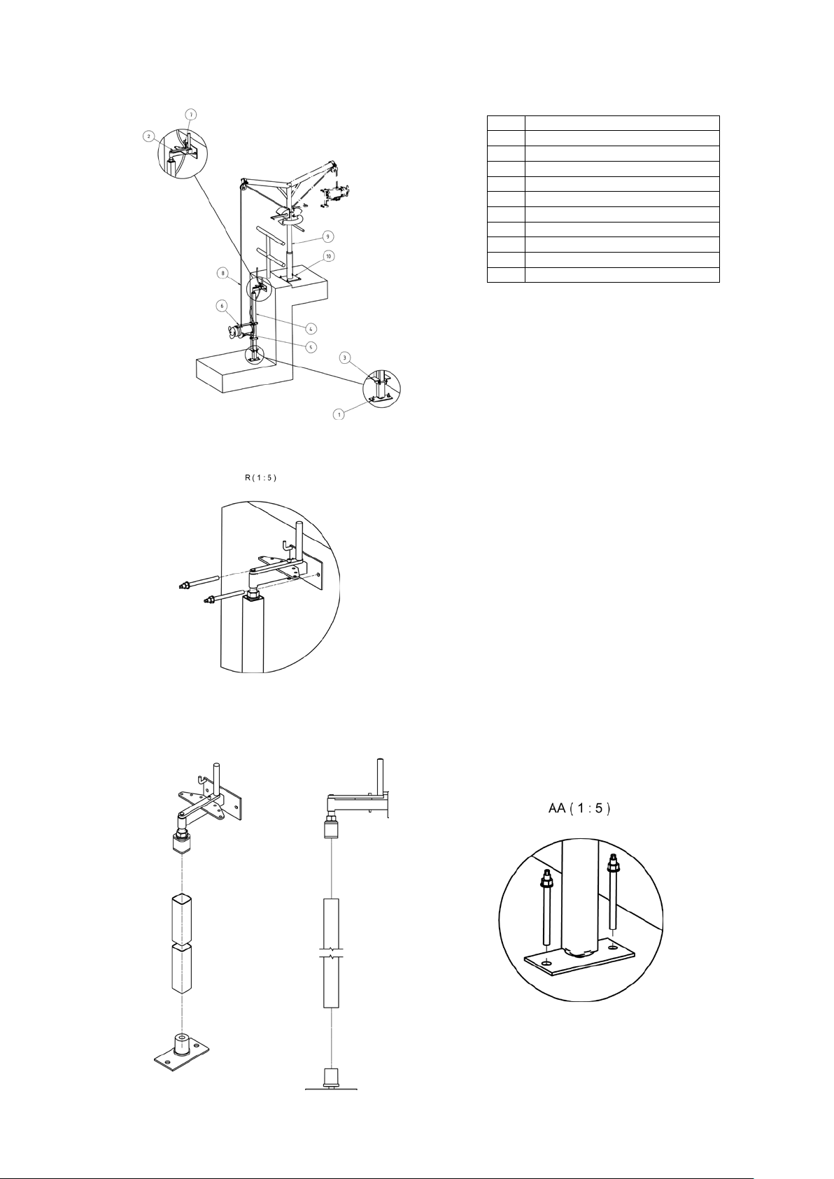
Assembling the motor bracket to the mixer
Fasten the mixer to the motor bracket (Item 12) as illustrated, using two cylinder head screws (Item 1), one
cylinder head screw (Item 2) and the associated U-washers (Items 3 & 4).
Lay the connecting cable between the pipe clamps (Item 6) and screw it to the motor bracket using two cylinder
head screws and U-washers (Items 5 & 4). Great care should also be taken to ensure that the cable is always laid
or assembled on a large radius, so that any sharp bend in the cable is prevented.
Lowering and guiding mechanisms
Before assembling the lowering and guiding mechanism, the local conditions governing installation (basin shape,
circulation conditions etc.) must be ascertained. It must be ensured that the mixer is freely mobile in the built-in
condition and that additional fittings have no effect on flow.
Page 14
44
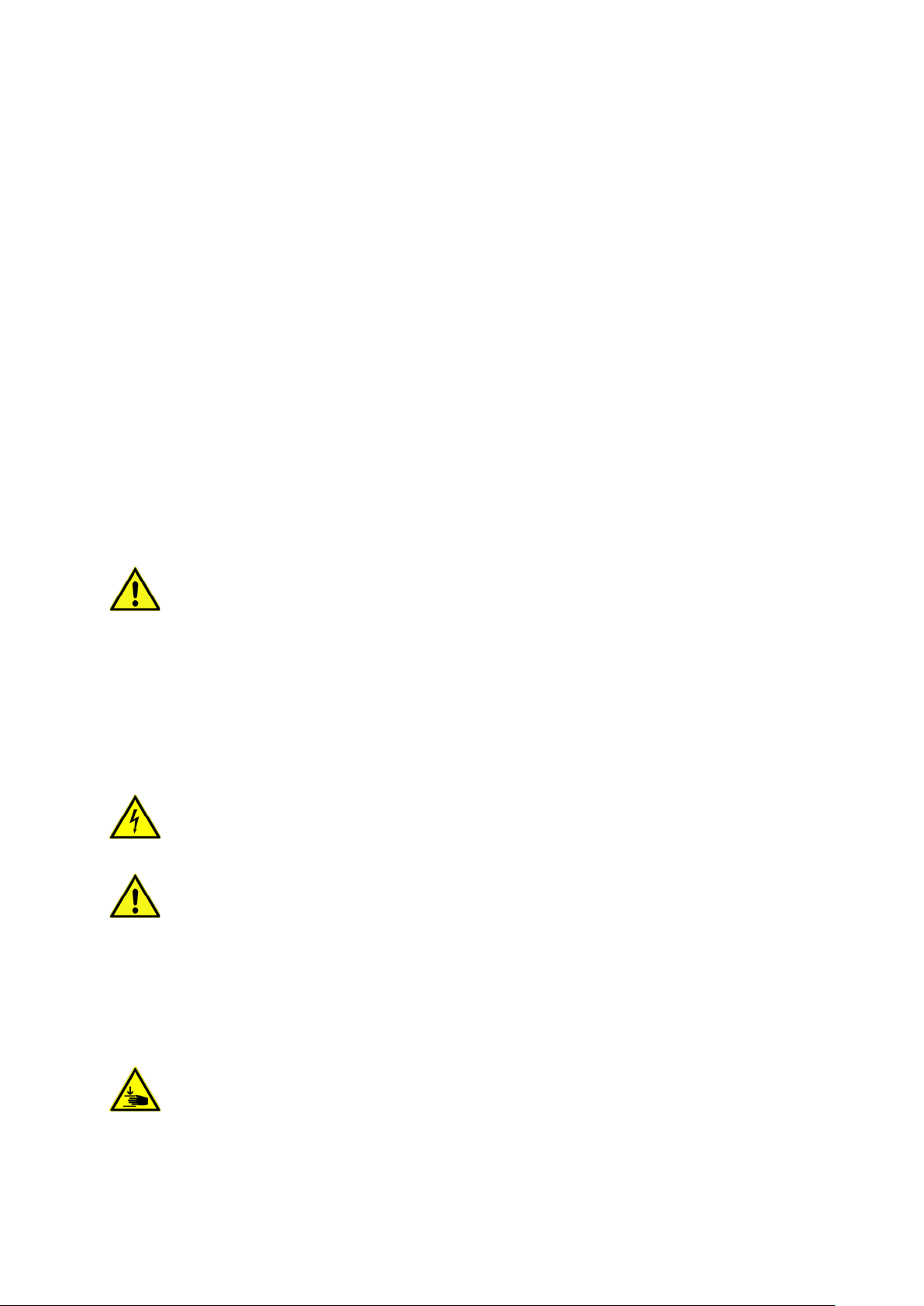
No.
Description
1
lower fastening
2
upper fastening
3
angle clamp bracket
4
square tube
5
mixer
6
motor bracket
7
cable anchor clamp
8
stainless steel w ir e
9
lifting gear
10
floor-mounted box column
The upper fastening (Item 2) must be attached in the basin first of all. Use the supplied anchor rods and bonding
anchor cartridges for this purpose.
In the next step, attach the square tube (Item 4, to be provided on site) to the upper and lower fastenings (Item 1).
Next, hold the upper fastening on the anchor rods intended for that purpose and fasten the anchor rods with the
nuts. The position of the lower fastening has now been determined. Use the supplied anchor rods and bonding
anchor cartridges for fastening it.
Page 15

45
Now install the angle clamp brackets (Item 3). These represent the bearing point of the motor bracket.
Now lower the mixer on to the bracket in the basin. When the motor bracket lies on the angle clamp bracket, the
connecting cable must be clamped in the cable anchor clamp. At the same time it must be ensured that the cable
is led upwards as tautly as possible so that it is not caught by the delivery flow.
5.3. Start-Up
The mixer must only be started when fully submerged, in order to prevent overheating of the
motor.
Any change of mixer position must only be done with mixer having been switched off and
propeller not rotating.
Before start up, check again that all steps of installation procedure have been properly carried
out. Make sure that the mixer is sufficiently submerged (see chapter 8+9), and that there are no solid
parts in the tank which might damage the propeller. Furthermore, it must be ensured that the mixer is
immersed at least half the diameter of the propeller.
Make sure that all necessary safety precautions have been carried out, e.g. to prevent persons from falling into
the tank. After longer standstill of the mixer, clean the propeller and motor surface from dried remains of mixing
liquid in order to prevent cooling problems.
5.4. Electrical system
Observe the relevant local and national regulations when laying out and selecting the electric lines as well as
when connecting the motor. The motor must be protected by a motor protection switch.
Have the motor connected in accordance with the "Wiring connection" data sheet. Pay attention to the direction of
rotation. If the direction of rotation is incorrect, the machine will not perform as specified, and under certain
circumstances, can become damaged. In accordance with the machine data sheet, check the operating voltage
and make certain that the current consumption remains uniform during all phases.
Make sure that all temperature sensors and monitoring devices, are connected and that their function is tested.
For details on this, see the wiring diagram.
Page 16

46
Beware of electrical current!
Incorrectly performed electrical work can result in fatal injury.
This work may only be carried out by a qualified electrician.
5.5. Motor protection
The minimum requirement is a thermal relay / motor protection switch with temperature compensation,
differential triggering and an anti-reactivation device in accordance with VDE 0660 or the appropriate national
regulations. If the machines are connected to electrical systems in which faults frequently occur, we recommend
installing additional protective devices (overvoltage, undervoltage or phase failure relays, lightning protection).
Local and national regulations must be adhered to when connecting the mac hin e.
5.6. Operation with a static frequency converter
The following points must be observed when operating the converter:
• T he pump is suitable for operation with the frequency converter according to DIN EN 60034-17.
• Voltage peaks at the motor winding must be avoided and, where appropriate, suitable filters must be
provided in the motor lead.
• T he proper groun din g of the e ntire sy ste m must be ensur ed.
• The specifications of the frequency converter manufacturer must be observed.
• Under certain circumstances, a shielded cable is necessary to comply with EMC directives.
• The information sheet "Using HOMA pumps with the frequency converter" must be observed.
5.7. Activation types
Activation types for cables with free ends (without plugs)
Star-delta activation
If the motor protection is installed in the line:
Set the motor protection to 0.58 x the rated current. The maximum start-up time in star-delta mode is 3 seconds. If
the motor protection is not installed in the line, set the motor protection to the rated current when fully loaded.
Starting transformer/soft start
Motor protection should be set to the rated current when fully loaded. At partial load, we recommend that motor
protection is set 5% above the measured current at the operating point. The maximum start-up time at reduced
voltage (approx. 70%) is 3 seconds.
Operation with frequency transformers
The machine can be operated on frequency transformers. Observe chapter 5.6 of this manual.
If the submersible mixers are operated with a frequency converter type HRG185, the evaluation of the PTC
thermistor must be done via a RL94/9/EC function-tested triggering device.
5.7.1. After Start-Up
The rated current is briefly exceeded during the start-up procedure. Once this process has ended, the operating
current should no longer exceed the rated current.
If the motor does not start immediately after the machine is switched on, it must be switched off immediately. The
start pauses specified in the technical data must be adhered to before starting up again. If the fault recurs, the
machine must be switched off again immediately. The machine may only be started again once the fault has been
rectified.
The following items should be monitored:
• Operating voltage (permissible deviation +/- 5% of the rated voltage)
• Frequency (permissible deviation -2% of the rated frequency)
• Current consumption (permissible deviation between phases is a maximum of 5%)
• Voltage difference between the individual phases (max. 1%)
• Starts and stops per hour (see technical data)
• Minimum water immersion level, level control unit, dry-run protection
• Smooth running
• Check for leaks, if need be, follow the necessary steps as set out in “Maintenance”
Page 17

47
6. Maintenance
6.1 General
The machine and the entire system must be inspected and maintained at regular intervals. The time limit for
maintenance is set by the manufacturer and applies to the general conditions of use. The manufacturer should be
consulted if the system is to be used with corrosive and/or abrasive pumped liquids, as the time limit between
inspections may need to be reduced.
Note the following information:
• The operating and maintenance manual must be available to the maintenance personnel and its
instructions followed. Only the repair and ma inte nance measures listed here may be performed.
• All maintenance, inspection and cleaning work on the machine and the system may only be carried
out by trained specialists exercising extreme care in a safe workplace. Proper protective clothing is
to be worn. The machine must be disconnected from the electricity supply before any work is carried
out. There must be no way that it can be inadvertently switched on. Additionally, the appropriate
protective measures as defined by the BGV/GNV should be enforced when working in basins and/or
containers.
• Above a weight of 50kg, only hoisting gear which has been officially approved and which is in a
technically perfect condition should be used for lowering and raising the machin e.
Make sure that all fastening devices, ropes and safety devices of the hand winch are in a technically
perfect condition. Work may only commence if the auxiliary hoisting gear has been checked and found to
be in perfect working order. If it is not inspected, danger to personnel may result!
• Wiring work on the machine and system must be carried out by an electrician. For machines
approved for work in areas subject to explosion danger, please refer to the “Explosion protection in
accordance with the regulation” chapter.
• When working with inflammable solvents and cleaning agents, fires, unshielded lighting and
smoking are prohibited.
• Machines which circulate fluids hazardous to health, or which come into contact with them, must be
decontaminated. It must be ensured that no dangerous gases can form or are present.
• Ensure that all necessary tools and materials are available. Tidiness and cleanliness guarantee safe
and problem-free operation of the machine. After working on the machine all cleaning materials and
tools should be removed from it. All materials and tools should be stored in an appropriate place.
• Operating supplies such as oil and lubricants must be collected in appropriate vessels and properly
disposed of (in accordance with the 75/439/EEC directive and with §§5a, 5b AbfG). Appropriate
protective clothing is to be worn for cleaning and maintenance jobs. This is to be disposed of in
accordance with waste code TA 524 02 and EC Directive 91/689/EEC. Only lubricants expressly
recommended by the manufacturer may be used. Oils and lubricants should not be mixed. Only use
genuine parts made by the manufacturer.
A trial run or functional test of the machine must be performed as instructed in the general operating
conditions.
Before maintenance or repair disconnect the mixer from the power supply to prevent accidental starting
of the mixer!
In accordance with the product liability law we point out that we shall not be liable for damages caused by
our product due to unauthorized repair by persons other than the manufacturer or an authorized workshop or due
to the use of spare parts other than original HOMA parts. The same product liability limitations are valid for
accessories.
Before maintenance or repair make sure that all rotating parts stand still!
Before carrying out maintenance and service, the mixer must be thoroughly flushed with clean water.
When loosening of the oil chamber control screw , overpr essur e can escape. Relea se the s crew only
when pressure balance is secured.
If not otherwise stated, the torque values of the be-low tables should be used.
Values stated are for clean, lubricated screws.
Page 18

48
Fixing torque [Nm] for screws A2/A4
A2/A4,
Hardeness class 70
A2/A4,
Hardeness class 80
DIN912/DIN933
DIN912/DIN933
M6
7 Nm
11,8 Nm
M8
17 Nm
28,7 Nm
M10
33 Nm
58 Nm
M12
57 Nm
100 Nm
M16
140 Nm
245 Nm
M20
273 Nm
494 Nm
(Coefficient of friction = 0,2)
6.2. Maintenance
It is imperative to keep a maintenance list to be always informed about the submersible mixer. This list must be
presented to the trade association, the technical inspection agencies and the manufacturer of the system or of the
mixer when requested.
The full warranty requires the annual inspection of the mixer by the manufacturer of the system or of the mixer.
6.2.1. General (Monthly or every 500 operating hours)
Clean the mixer from all attached solids. Check the motor cable for damages. In case of any damages of cable
surface replace cable through mixer manufacturer or authorized repairshop.
Check mixer painting and surface for scratches or damages. Repaint surface or replace damaged parts.
6.2.2. Electric Motor
The current consumption must be checked for all 3 phases monthly. Damages of the motor, transmission and
bearing can be detected via the power consumption.
Lubrication: The bearings are lubricated for life (when noises arise, bearings must be replaced at the manufacturer's works).
The oil in the oil chamber should be changed after every 6000 hours of operation.
Oil condition: Place mixer horizontally so that one of the oil chamber screws is at the top. Remove the screw and
extract a small amount of oil. If the oil is milky or cloudy, it indicates a defective shaft seal. In this case, have the
condition of the shaft seals checked by HOMA-workshop or factory service.
Replace shortages
Isolation test: If the insulation resistance is less than 2 megohms, do not turn the submersible mixer on. (Measuring DC voltage 1500 Volts).
6.2.3. Stirring Propeller
Inspection: Inspect the stirring propeller periodically. Remove random wound foreign bodies such as twines,
cords, etc. They can cause uneven running and thus create strong vibrations in the system and can lead to
damage on the mixer components. With uneven running, the stirring propeller must be cleaned.
6.3. Change of oil
position when changing oil.
When releasing the oil level screws, excess pressure may escape from the oil chamber or the gearbox. Only
remove the screws completely after the pressure was equalized.
The thread and the magnets (on the gearbox) of the screws must be clean before screwing them back on.
The sealing rings must be always replaced with new parts.
Change oil only with motor at operation temperature. Note that the mixer must be in a horizontal
Page 19

49
6.3.1 Oil chamber
Oil specification: bio degradable Shell Ondina 917. Remove used oil according to local regulations! Oil capacity is
1,0 liter.
Steps:
1. Remove screw
2. Release oil
3. 4. Fill in correct quantity of oil (see below table)
5. Re-fasten screw
Page 20

50
7. Additional for FM submersible pumps
7.1. GENERAL INSTRUCTIONS
This manual is intended to provide basic installation and start-up guidance. It is to be read and thoroughly studied
prior to attempting to install or operate any of the equipment supplied. Equipment damage, which occurs by not
following these instructions will void the warranty.
7.2. SAFETY PRECAUTIONS
Only trained qualified personnel shall be utilized for installation and start-up.
The following is a general list of safety precautions that should be followed when installation starting-up or
servicing the pump.
The pump station owner or operator is ultimately responsible for ensuring that all equipment is installed,
started up and operated in a safe manner.
• Do not work alone.
• Double check to make sure that all lifting equipment is in good working order and that it has adequate lifting
capacity for the weight that it will handle.
• Wear safety helmet, goggles and protective shoes, or appropriate safety materials required.
• Before working on the pump make sure that the power is disconnected and cannot be energized by others.
Lockout and tag the control panel circuit breaker.
• Do not stand under suspended loads!
• Never enter or work within a wet well without first checking to make sure sufficient oxygen is present and that
there are no explosive or poisonous gases present.
• All personnel, who work with sewage pumping equipment and systems shall be vaccinated against diseases
that can occur. If there are any questions or doubts in this area it is strongly suggested that the local health
agency be contacted.
• For Hazardous Area Classifications, only use pumps with suitable Explosion Proof Rating.
7.3. EQUIPMENT INVENTORY AND INSPECTION
Upon arrival of pump shipment carefully unpack all components and compare with shipping and purchase order
documents to ensure that the order is complete. Also inspect equipment for any damage that might have occurred
in shipment. If any problems are detected contact an authorized HOMA customer service immediately.
7.4. TRANSPORTATION AND STORAGE PROCEDURE
Always lift the pump by its lifting bail or eye bolt.
Never lift the pump by its power cable! Jacketed pump should never stored or shipped with the
pump by the jacket. Damage to Sealing O ring may result.
Pumps should be stored in an upright position, taking extreme care to protect the power cable and control cables
from crushing, nicks or tears which would permit water intrusion.
Power cable ends must be protected from immersion in water as well as moisture intrusion. The cable will wick
water into the pump if it is not protected properly. Power cable leads should be covered with shrink tubing or
suitable sealing material durin g storage.
Short Term Storage: Short term storage is defined as any time less than six months. We recommend that pump
and accessories be stored in its original shipping container in a dry, temperature controlled area. If climate
controlled storage is not possible, all exposed parts should be inspected before storage and all surfaces that have
the paint scratched, damaged or worn should be re-coated with air dry enamel paint. The pump should be stored
in an upright position.
Long Term Storage: Any storage time exceeding six months is considered long term. In addition to the
safeguards specified above, the impeller should be rotated once a month to prevent the mechanical seals from
being damaged, and the pump should be inspected. The seal chamber oil should be drained and replaced prior to
commissioning. The pump should be stored in an upright position.
Page 21

51
7.5. ELECTRICAL INSTALLATION
7.5.1. GENERAL GUIDELINES
All electrical work shall be carried out under the supervision of an authorized, licensed electrician. The present
state adopted edition of the National Electrical Code as well as all local codes and regulations shall be
complied with.
7.5.2. VERIFICATION OF POWER SUPPLY
Prior to making any electrical connections or applying power to the pump, compare the power supply available at
the pump station to the data on the unit's nameplate. Confirm that both voltage and phase match between pump
and control panel. The voltage supplied at the pump shall be +5 / -10% of the nameplate value, frequency shall be
+ / - 1% of the nameplate value, the voltage phase balance shall be within 1% and the maximum corrected power
factor shall be 1.0.
7.5.3. POWER LEAD WIRING
HOMA pumps may be provided with 1 or more cables, depending on motor horsepower and operating voltage.
Power leads L1, L2, & L3 may be provided as single conductor, or as multiple conductors. Multiple conductor
configurations may use leads from separate cables, or may use two conductors within one cable. Please refer to
wiring diagram in the appendix for specific connection details. The pump must be connected electrically through a
motor starter with proper circuit breaker protection in order to validate warranty. Do not splice cables.
7.5.4. THERMAL SWITCH WIRING
Pumps are equipped with thermal switches embedded in the stator windings which are normally closed,
automatically resetting switches. Switches will open when the internal temperature rises above the design
temperature, and will close when the temperature returns to normal. Thermal switches must be wired to a current
regulated control circuit in accordance with the NEC.
Identify thermal switch leads marked T1 and T3 in the power or control cable.
The resistance across the leads will be 0.5 Ohms. Thermal leads must be connected to the thermal overload relay
located in the control panel. Thermal switch leads must be connected to validate warranty.
Note: All sizes of Class 1, Div. 1 pumps for hazardous service must have thermal switch leads connected
to a current regulated control circuit in accordance with NEC.
7.5.5. SEAL PROBE WIRING
The mechanical seal leak detector probe utilized in the pump is a conductive probe which is normally open. The
intrusion of water into the seal chamber completes the electrical circuit. Control panel provisions will sense this
circuit closure, and will provide indication or alarm functions depending on the panel design.
Either single or dual wire systems may be provided. Single wire systems utilize one energizing conductor, and the
pump casing and neutral lead as the ground or return portion of the circuit. The dual wire systems utilize two
separate conductors for each leg of the circuit.
With either system, the seal probe leads must be wired into a control circuit provided in the control panel. This
control circuit must energize the probe with a regulated power source, and sense the closed circuit in event of
water intrusion Indication and alarm functions must also be provided in the control circuit. Please see c ontrol
panel wiring diagram for seal probe connection points.
For Hazardous Area Classification Pumps, leak detector circuit must be in conformance with applicable NEC
codes and regulations.
7.5.6. START / RUN CAPACITORS AND RELAYS:
All single phase motors require start and run capacitors along with a start relay to operate. Capacitors and relays
must be sized for the specific motor.
Capacitors are sized based on ideal conditio ns.
The run capacitor may need to be resized to match the available field voltage. Each cap kit shipped is supplied
with a wiring diagram and start up procedure.
7.5.7. Variable Frequency Drives
Special considerations must be taken when operating pumps with variable frequency drives (inverters).
The inverter circuit design, horsepower required by pump, motor cooling system, power cable length, operating
voltage, and anticipated turndown ratio must be fully evaluated during the design stage of the installation.
As a minimum, properly sized load reactors and filters must be installed between the inverter and the
pump to protect the pump motor from damaging voltage spikes. Warranty coverage will not be provided on
any pump motor that is operated with a variable frequency drive, unless the load side of the inverter is properly
isolated from the pump.
Page 22

52
7.6. ADDITIONAL PUMP PROTECTIVE DEVICES
Several optional pump protection devices are available to protect submersible motors from damage, and may
have provided in your pump.
Temperature Sensing RTD*: PT100 sensors are available in two critical locations on larger machines, the lower
bearings and motor windings. N.C. Circuit - 108 ohm
Moisture Sensors: Two styles of moisture sensors are available on HOMA pumps.
Moisture Detectors*: These are micro float switches designed to detect small amounts of liquid. These are
available in the stator housing of 50hp and larger size pumps. N.C. Circuit - 268 ohm
Leakage Detectors*: These normally open, single or 2 wire probes are used to detect the presence of water in the
pump. Single wire probes use the pump ground to complete circuit. Optional leak detectors can be installed as
follows:
• Stator Chamber installation: Probe placed in bottom of stator housing to detect presence of w at er in the
chamber.
• Stator or Motor cap installation: Probe used to detect the presence of water only into the stator housing
or motor cap terminal board.
• Closed loop cooling Installation: Probe placed in stator housing to detect the presence of liquid in the dry
chamber.
* relay is required for sensor operation.
7.7. MECHANICAL INSTALLATION
7.7.1. PUMPS WITH AUTOCOUPLING SYSTEMS
The HOMA Auto-Coupling is a quick removal system used in keeping personnel from having to enter the wet well.
The pump mounts on a stationary base and operates completely or partially submerged (minimum 10” over
volute) in the pumping media.
The HOMA Auto-Coupling kit consists of a base, guide claw flange, upper guide rail bracket, profile seal and base
anchor bolts. Refer to dimensional drawing for details.
For all pumps, attach the guide claw flange to the pump discharge flange with the fasteners and gaskets included
with the auto-coupling kit. Use tightening torque’s indicated i n the table below. Do not over tighten! Install the
profile gasket (if not already installed at the factory) into the guide claw with the large diameter fitted into the
groove inside the claw. Refer to the diagram included with the auto-coupling kit for proper profile gasket
installation.
Install suitable lifting chain of an adequate size and length to permit proper lowering and raising of the pump.
Properly locate the base and with the anchor bolts fasten to the floor of the pump station. Make sure when
locating and securing the anchor bolts that the base will align properly with the access cover at the top elevation
of the station. Place the base in position, and level the base.
If the base is not level, proper sealing of the pump to base may not occur!
Place the guide rails (supplied by others), cut to length in to the rings of the base. The rails will be secured at the
top of the pump station with the upper guide bar bracket and to extend down to the sump floor.
For stations exceeding 10 feet in depth intermediate guide bar brackets are recommended. One bracket is
recommended for each additional 10 feet of station depth.
Check that the guide system is properly installed in the vertical orientation by using levels and a plumb line. Fully
tighten all anchors and mounting bolts.
Connect the station riser piping to the outlet flange of the base.
Before lowering the pump, verify the direction of impeller rotation (refer to start-up section for procedure).
Make sure to use lifting equipment that has adequate capacity for the pump that will be handled. Before
installing pump, check to be certain the profile seal (rubber ring) is properly positioned in the guide claw flange.
Then position pump so the guides on the discharge flange engage the rails. Slowly lower the pump along the
guide rail. Once the pump reaches its bottom location it will automatically connect to the base.
It is recommended that the stationary base elbow be visible before lowering the unit. If this is not possible, ensure
all debris is removed from wet well.
Do not install more than one check valve into any piping system or problems will occur.
Page 23

53
7.7.2. INSTALLATION OF PUMPS WITH RING STANDS
The ring stand design allows for a free standing, simple economical installation or to be transportable from one
installation to another.
It is intended to operate completely or partially submerged in the pumping liquid.
Install the ring stand to the underside of the volute with the supplied fasteners provided. Apply thread locking
compound and tighten the bolts using the torque table indicated in the table. Do not over tighten! Install suitable
lifting devise of an adequate length to ensure proper lowering and raising capabilities. Lower the pump into the
area where it is required. Properly position power cable and chain so they stay above pump and cannot enter the
pump suction.
7.7.3. INSTALLATION OF PUMPS FOR DRY PIT APPLICATIONS
Foundation and Piping Requirements:
General
The following recommendations are basic guidelines which are intended to outline basic requirements in the
design of the dry pit station. It is essential that a licensed professional engineer be retained by the owner to
design the station and all support structures .
Foundations
Foundations may consist of any structure heavy enough to provide permanent rigid support for the pump and inlet
elbow stand. Concrete foundations built up from the solid ground are the most commonly used. The concrete floor
shall be level. The space required by the inlet stand and the location of the foundation anchor bolts are shown on
the outline dimension drawing. Foundation bolts are to be embedded in the concrete.
Suction Piping
Suction piping should be at least as large as the pump inlet elbow suction. If reducers are utilized they should be
of the conical type. If the liquid source level is below the volute horizontal centerline, the reducer must be
eccentric and installed with the level side up. If the liquid level is above the pump volute horizontal centerline,
either eccentric or concentric reducers may be used. Suction piping should be run as straight as possible. All pipe
flange joints should be gasketed to prevent air from entering the pipe. High points that may collect vapor are to be
avoided. Isolation valves such as gate valves can be installed in order to facilitate the removal of the pump for
maintenance. Any valve installed in the suction line should be installed with the stems horizontal.
Discharge Piping
A check valve and isolation valve shall be installed in the discharge line. The check valve should be installed
between the pump discharge flange and the isolation valve. If pipe increasers are used on the discharge line, they
should be placed between the check valve and the pump.
The inlet elbow stand allows the pump to be installed in a stationary position in a dry pit. Place the inlet stand in
position and tighten the anchor nuts.
Lower the pump on to the top flange of the inlet stand. DO NOT ALLOW SLACK ON THE LIFTING CABLE
UNTIL THE PUMP IS BOLTED DOWN. Make sure the flange bolt holes align with the mounting holes on the
underside of the volute. Secure the pump to the mounting flange with the fasteners that are specified in the
accessory fastener selection table below.
Page 24

54
Bolts
PUMP MODEL
Anchors
SIZE
TORQUE
3”
8
M16X60mm
146 Nm / 108 ft lb
AUTOCOUPLING
4
M16
100 Nm / 74 ft lb
AUTOCOUPLING
4
M16
100 Nm / 74 ft lb
3” & 4”
4
M16x25mm
146 Nm / 108 ft lb
RING STAND
3” & 4”
8
M16x40mm
146 Nm / 108 ft lb
AUTOCOUPLING
4
M16
100 Nm / 74 ft lb
6"
4
M20x40mm
200 Nm / 150 ft lb
DRY SUMP (1 Piece)
4
M16
100 Nm / 74 ft lb
6"
8
M20x65mm
200 Nm / 150 ft lb
DRY SUMP (N/PMotor)
4
M16
100 Nm / 74 ft lb
6"
8
M20x70mm
200 Nm / 150 ft lb
DRY SUMP (F Motor)
4
M16
100 Nm / 74 ft lb
8”
8
M20x70mm
200 Nm / 150 ft lb
AUTOCOUPLING
4
M20
200 Nm / 150 ft lb
8"
4
M20x30mm
200 Nm / 150 ft lb
8"
8
M20x75mm
200 Nm / 150 ft lb
4” 8 M16X60mm 146 Nm / 108 ft lb
DRY SUMP 4 M16 100 Nm / 74 ft lb
6” 8 M20x70mm 200 Nm / 150 ft lb
RING STAND
6" 8 M20x45mm 200 Nm / 150 ft lb
RING STAND
DRY SUMP (2 Piece) 4 M20 200 Nm / 150 ft lb
Notes:
7. For pumps larger than 8” please consult factory.
8. Flange bolts must be tightened in cross pattern to avoid damage to the raise face flanges.
9. Standard flange bolts are 316SS
10. Standard anchors are plated steel.
11. Autocoupling systems include qty. 4 M12 anchors for the upper bracket. Torque to 51 Nm / 38 ft lb.
12. Anchor bolt holes should be drilled to the actual diameter of the anchor (M12 anchor requires 12mm
diameter hole).
7.7.4. JACKETED PUMP OPTION
The cooling jacket has been supplied based upon the specified operating conditions of this application. It is
important this jacket is function properly, or the internal motor components could become damaged.
Several cooling configurations are available depending upon customer preference and system requirements. You
must know what configuration of cooling system is to be used with the pump prior to installation. In some cases,
field test results may indicate a change of cooling method is required. Consult factory for necessary changes to
the pump.
Cooling Requirements
1 - Standard Media Cooled – This construction does not require any external piping and it is completely self-
contained. This design is suitable for the routine collection system application. No pump modifications are
required.
Required Hardware – Automatic air bleed valve mounted in upper vent port or a ¼” or 3/8” elbow and small
block valve for venting. A length of hose routed to the sump should be attached to either air bleed or the
block valve outlet.
Start Up Requirements – This jacket must be vented at start up. Additional venting may be required after
situations where the suction or discharge piping has been removed for maintenance and reinstalled. Some
adverse operating conditions can allow air to become trapped in this jacket. This must be periodically vented
off. If this occurs, it is recommended the small air bleed valve is utilized.
Page 25

55
2 - Media Cooled with External Flush - This construction requires an external flow of water, typically re-use
water. Applications which require this option are typically heavy slurry or sludge service often found in the
treatment plant. This option routes the externally supplied water into the pumped media. No pump modifications
are required.
Required Hardware – Mounting a regulating valve, pressure gauge and automated block valve between the
water supply and the upper jacket port is required. The supply valve should be adjusted to allow the supply of
water to exceed pump discharge pressure. This assures a positive flow of water into the pump chamber. The
block valve should be automated to open whenever the pump is operated.
Start Up Requirements – This jacket must be vented at start up. Additional venting may be required if cooling
water supply is interrupted.
3 - External Fluid Cooled - This option requires an external flow of water like in option 2 above, but is used
where dilution of the pumped product is not desirable. The supply of water is internally isolated from the pumped
media. The water inlet is routed into the jacket’s lowest port and returned out of the highest port. This option does
NOT allow water to enter the pumped media and pump must be ordered from factory this way.
Required Hardware – Mounting a regulating valve, pressure gauge and automated block valve between the
water supply and the upper jacket port is required. The supply valve should be adjusted to allow for a good
supply of water to flow through the jacket. The block valve should be automated to open whenever the pump
is operated.
Start Up Requirements – This jacket must be vented at start up. Additional venting should not be required.
Vent Valve Installation
HOMA dry pit pumps are supplied with a valve and fitting that must be installed and maintained to ensure the
proper performance of these pumps.
The opening for this valve is located on the base of the motor cap near the mounting screws. The pump is
shipped with a plug installed which must be removed prior to start up.
This opening is a metric straight thread and requires an adapter included with the valve and fitting hardware. It is
also recommended that a length of hose be attached to the valve and routed back to the sump.
Note: Leave vent valve open in wet pit pump application to
prevent air entrapment in jacket.
Page 26

56
7.8. INSTALLATION / START UP TROUBLESHOOTING:
Only authorized service personnel who are trained professionals shall troubleshoot and repair pumps that are
experiencing operational or performance difficulties.
All HOM A pumps are factory tested, yet startup difficulties can occur with any mechanical equipment.
Please note that our technical support staff stands ready to assist you with any problem or difficulty you
might encounter with our equipment.
The following is a tabulation of common start-up problems and possible causes.
Symptom: Possible Causes
Pump will not start: 1, 2, 3, 4, 27, 28, 29, 31, 32
Little or zero discharge: 5, 6, 7, 8, 16, 30, 32
Insufficient discharge flow/pressure: 5, 6, 9, 10, 11, 12, 26, 30
Excessive power consumption: 6 , 9 , 13, 28, 30
Excessive current draw: 6, 13, 14, 15, 19, 26, 30
Excessive pump vibration/noise: 12, 15, 16, 25, 26, 28, 31
Pumps runs & motor protection trips: 17, 18, 19, 20, 21, 28
Pumps run manually, but not automatically: 22, 23, 24
Pump runs hot: 7, 19, 25, 26, 28
Listing of Possible Causes:
28. Incorrect or no power supplied to motor.
29. Power cable cut.
30. Short to ground in cable or motor winding.
31. Control panel circuit breaker open.
32. Actual system head is higher than calculated or specified.
33. Incorrect impeller rotation direction.
34. Sump liquid level is below pump's minimum submerg enc e require me nt .
35. Closed discharge valve or jammed check valve.
36. Wear ring(s) worn. (If Applicable).
37. Vortex at pump's suction.
38. Discharge valve partially closed.
39. Insufficient NPSHA (Dry Pit Application).
40. Actual system head is lower than specified resulting in over pumping condition.
41. Voltage supply to motor is lower than required by motor.
42. Damaged bearings.
43. High system head causing pump to operate at extremely reduced capacity.
44. Object stuck inside impeller.
45. Motor not receiving proper voltage on all three phases.
46. Phase/currents unbalanced or too high.
47. Insulation between phases and earth ground, <1M-ohm.
48. Density of the pumping media too high.
49. Defective level sensor.
50. Hand/Off/Auto switch not in Auto Position.
51. Defective H/O/A switch, relay or contactor coil.
52. Air Captured in Cooling Jacket.
53. Pump not properly seated on Auto Coupling.
54. Water intrusion through junction box.
28. VFD or Soft Start not functioning properly.
29. Run capacitor size to large (1ph).
30. Start capacitor size to small (1ph).
31. Profile seal not sealing or missing.
32. Start relay or capacitor damaged (1ph).
Please note that some possible causes may not relate to your particular model.
Page 27

57
7.9. MAINTENANCE
Regular maintenance will help ensure longer pump life and more reliable operation. It is recommended that
pumps in intermittent operation be inspected twice a year and pumps in continuous operation be inspected every
1,000 hours. The following is a listing of required inspection and maintenance items.
If any of the problems described in the following list exists, stop operating the pump to avoid damage or
personal injury.
1. CABLE ENTRY
Make sure that the cable entry flange and strain relief clamp are tight. If the cable entry is showing signs of
leakage remove cable from entry, remove grommet, cut a piece of cable off so that the grommet seats on a new
portion of the cable, replace grommet, and re in stal l cabl e ass embly , into the top of the moto r.
Note: Explosion Proof cables are sealed with a Factory Mutual Approved potting compound. Please consult
factory for instruction.
2. CABLES
Inspect the cable for cuts, scrapes or sharp bends. If the outer jacket is damaged, replace the cable. Splices of
the power or control cable within the wet well area are not acceptable.
3. MOTOR INSULATION RESISTANCE
Megger the insulation between the phases; and between any phase and ground. Resistance values should be
greater than 1 M ohm. If abnormal readings are obtained, contact authorized service center immediately.
4. EXTERNAL PARTS ON PUMP
Make sure that all screws, bolts and nuts are tight. Check the condition of pump lifting eyes and replace if
damaged or worn, Replace any external part that appears worn or damaged.
5. SEAL CHAMBER OIL
Note: Use extreme care when removing the seal chamber plug, as the chamber may become pressurized if seal
failure has occurred.
Seal chamber oil should be checked for signs of water intrusion, or other impurities any time the pump is removed
from wet well. To check the condition of the oil, remove the oil fill plug. Drain the chamber volume into a
transparent container. Visually check sample for impurities or emulsification (oil may appear cream-like if a sma ll
amount of water is present). If significant water intrusion has occurred, remove and replace lower mechanical
seal. Unless obvious mechanical damage has occurred to the lower seal, it is good practice to replace the upper
and lower mechanical seals as a set. Refill seal chamber with fresh oil to the bottom of fill plug port (when pump is
in vertical position) and replace oil fill plug.
6. IMPELLER
Periodically inspect impeller by turning pump on its side, remove suction strainer nuts and strainer to expose
impeller and relocate position of adjusting plate (suction cover) as needed. Replace the impeller if it is damaged
or worn.
7.10. SPARE PARTS
In order to obtain spare parts identify the required parts, and contact authorized HOMA customer service with
your order. Authentic HOMA parts shall be used to maintain warranty.
Explosion Proof pumps must be identified as such, and the pump serial number must be referenced for
proper parts identification.
7.11. RECOMMENDED TOOLS AND SUPPLIES
In addition to ordinary maintenance and lifting devices, ensure that complete set of metric Allen wrenches,
impeller puller, bolt adhesive and Anti-seize compound are on hand.
Page 28

58
7.12. PROFILE SEAL INSTALLATION
Black Rubber Sealing Ring (Profile Seal) must be installed in the Guide Claw before pump is installed. Ring must
be installed with the large diameter lip inside the groove of the Guide Claw Flange.
CALL OUR TECHNICAL SUPPORT GROUP WIT H ANY QUESTIONS REGARDING THE INSTALLATION OF
THIS EQUIPMENT.
7.13. SEAL PROBE INSTALLATION PROCEDURE
Mechanical Seal Leak Detection probe has been loose to protect from shipping damage. Please follow
this procedure to install the probe.
8) Lay pump on its side with the plug on the seal chamber facing upwards as indicated.
9) Unscrew the plug with the proper wrench, taking care not to damage the sealing surface.
10) Verify that seal chamber oil level is within ¼” of the indicated value. Measurement is from oil level to the
top of hole. See IOM Manual for seal chamber oil volume, if required.
11) Remove the new sealing gasket from package and install it onto the seal probe plug.
12) Install the seal probe with gasket into the opening, taking care not to damage the cable. Then tighten the
seal probe with the proper wrench until snug. Do not overtighten. O nc e tight, verify the seal gasket is
properly seated and the cable is not pinched or twisted.
NOTE: At installation of the seal probe be careful not to bind the seal probe cord as it is being installed into
the pump.
13) Lift pump into a vertical position and inspect for any leaks.
14) Secure seal probe cable to pump body and power cable with tyraps before installing pump.
Page 29

59
External Seal Probe Connections
7.14. SINGLE PHASE PUMP START-UP PROCEDURE
Run Capacitor sizing can vary depending on the incoming supply voltage provided. HOMA Single Phase pumps
are provided with Start and Run Capacitor(s) sized for 220-230V under load. Frequently, the available line voltage
is considerable different than indicated, and the Run capacitor(s) may need to be resized to match the available
field voltage. The following procedure will allow you to verify proper operation of your single phase pump, and/or
make necessary changes to you capacitors to correct for your power supply.
After verifying wiring is in accordance with your pump requirements, start pump and record the following readings
from each of the (3) pump cable leads.
Current under load:
U1 Amps,> U2 Amps,> Z2 Amps
Should be (highest reading) (middle reading) (lowest reading)
Lead U1 (common) should have the highest current reading. Lead Z2 (start) should have the lowest reading.
If Z2 current draw is greater than the current draw of either U1 or U2, a smaller size Run capacitor (lower
microfarad rating) is required to correct the condition. Example: If a 60 µf Run capacitor was supplied, change to a
50 µf Run capacitor and check current readings. Typically, only one step down in capacitor size is required, but in
certain instances 2 steps may be required.
( ) The standard capacitor kit provided includes: ____________µf start capacitor
____________µf run capacitor.
( ) Additional run capacitors have been included for use in tuning the pump to match available line voltages for
optimum performance.
___________µf run capacitor
___________µf run capacitor
___________µf run capacitor
This form is provided for your use in optimizing the performance and service life of your single phase pumps, and
is applicable to most Capacitor Start/Capacitor Run motors. Please contact our customer service with any
questions or if you require any additional information or assistance.
Page 30

60
7.15. TECHNICAL DETAILS
HP / RPM
Resistance Readings (ohms)
Pump Weight
230V / 1Ph
230V / 3Ph*
460V / 3Ph*
U1 - U2 / U1 - Z2
U-V-W
U-V-W
2.5HP / 1750 D
2.2 / 5.0
1.5
5.0
230 lbs / 104 kg
2.8HP / 1160 T
N/A
2.7
5.0
230 lbs / 104 kg
2.9HP / 1750 N
2.2 / 5.0
3.1
11.0
230 lbs / 104 kg
2.9HP / 1750 T
3.1
11.0
230 lbs / 104 kg
3.5HP / 1750 D
N/A
1.9
5.5
230 lbs / 104 kg
3.8HP / 1160 T
N/A
1.5
2.5
240 lbs / 108 kg
4.3HP / 1750 N
1.5 / 3.0
1.5
4.2
240 lbs / 108 kg
4.3HP / 1750 T
1.5
4.2
240 lbs / 108 kg
5.1HP / 1750 T
1.1 / 2.6
N/A
N/A
250 lbs / 113 kg
5.5HP / 1750 N
/ 1.9
1.3
3.7
250 lbs / 113 kg
5.5HP / 1750 T
N/A
1.3
3.7
250 lbs / 113 kg
6.2HP / 1160 T
N/A
1.3
3.7
250 lbs / 113 kg
6.7HP / 1750 T
0.7 / 1.9
N/A
N/A
260 lbs / 118 kg
7.5HP / 1750 N
/ 1.5
0.9
2.6
260 lbs / 118 kg
7.5HP / 1750 T
N/A
1.2
3.0
260 lbs / 118 kg
8.3HP / 1160 T
N/A
0.9
2.6
260 lbs / 118 kg
9.7HP / 1750 T
0.5 / 1.4
N/A
N/A
260 lbs / 118 kg
9.8HP / 1160 P
N/A
0.7
2.2
290 lbs / 132 kg
10HP / 1750 N
0.3 / 0.9
0.6
1.9
290 lbs / 132 kg
10HP / 1750 T
N/A
0.6
1.9
290 lbs / 132 kg
11.4HP / 1750 T
0.4 / 0.8
N/A
N/A
290 lbs / 132 kg
13HP / 1750 P
N/A
0.5
1.8
350 lbs / 159 kg
15.3HP / 1160 P
N/A
0.5
1.1
350 lbs / 159 kg
20HP / 1750 P
N/A
0.5
1.1
400 lbs / 181 kg
21.5HP / 1160 P
N/A
0.5
1.1
400 lbs / 181 kg
29HP / 1750 P
N/A
0.4
0.7
500 lbs / 227 kg
3” / DN80 Discharge
4” / DN100 Discharge
6” / DN150 Discharge
8”+ / DN200+ Discharge
AK
min N/A
min 10”
min 13”
Please consult factory for
AV
min N/A
min 10”
min N/A
AMX
min 8”
min 10”
min 13”
The following is offered as a general guide to values and capacities commonly used.
*Values should be as indicated between any 2 power leads.
Note: Resistance values include 30’cable, and should be within +/- 10% of above value.
Above 30 HP, resistance values between 230 and 460 volt machines very by less than 0.1 ohm. Consult factory
with specific requirements.
Impeller Bolt Torque:
10mm – 26ft lb / 35Nm, 12mm – 45ft lb / 61Nm, 16mm – 108ft lb / 146Nm, 20mm – 210 ft lb / 285Nm
Impeller to Bottom Plate Clearance: (ASC) .020” / 0,3mm minimum clearance.
Pump Rotation: Right hand (CW) looking down from top of motor, CCW looking at bottom of pump.
Seal Probes: N motor pumps use a 12mm seal probe P motor pumps use 20mm seal probe.
Single wire probes are for non-classified areas, and 2 wire probes are for Hazardous areas.
Seal Chamber Oil: White Mineral Oil (Chevron Lubricating Oil FM 32, 46, 68)
Seal Oil Volume
All N frame motors 2.5L
All T frame motors 2.5L
All P frame motors 3.7L
Current D motors 9L
F, G & H FRAME SEAL OIL VOLUTE VARY BY HP, PLEASE CONSULT FACTORY W ITH SPECIFIC PUMP
MODEL.
Seal Oil Level
With pump lying on its side and oil port at 12:00, measure from the top of housing with gasket in place, to the oil
level.
T, N & P motors: 1 1/2” from top of housing to oil level
layout information.
Page 31

61
8.1. Anschluss von Pumpen und Rührwerken
Aderbezeichnung Motor
Klemme im
Schaltschrank
U1
U1
V1
V1
W1
W1
U2
U2
V2
V2
W2
W2
Aderbezeichnung Motor
Klemme im
Schaltschrank
U
U1 V V1 W W1
Aderbezeichnung Motor
Überwachungseinrichtung
Überwachungen in der Wicklung
T1 / T2
Temperaturbegrenzer (2 Schalter in Reihe)
T1 / T4
Temperaturregler (2 Schalter in Reihe)
T1 / T2 / T3
Temperaturbegrenzer und –regler
K1 / K2
PTC – Kaltleiter (3 Kaltleiter in Reihe)
PT1 / PT2
PT3 / PT4
PT6 / PT6
Lagerüberwachung
P1 / P2
PT100 Lager oben
P3 / P4
PT100 Lager unten
Dichtungsüberwachung
S1 / S2
Dichtungsüberwachung in der Ölkam mer
S3 / S4
Dichtungsüberwachung im An schlus srau m
Elektroden
Schwimmerschalter
S9 / S10
Dichtungsüberwachung im Getriebe
(Rührwerk)
S11 / S12
Dichtungsüberwachung im Lecka gerau m
Heizung
H1 / H2
Heizungseinrichtung
Gefahr durch elektrischen Strom!
Durch unsachgemäßen Umgang mit Strom besteht Lebensgefahr! Alle Pumpen mit freien Kabelenden
müssen durch einen Elektrofachmann angeschlos sen w er den.
8.1.1 Lastkabel
Pumpen in Stern-Dreieck Ausführung
Pumpen in Direktstart Ausführung
8.1.2. Steuerkabel
Je nach Ausführung der Pumpe / des Rührwerkes kann es sein das kein separates Steuerkabel verwendet wird.
Die Überwachungseinrichtungen sind dann mit dem Lastkabel ausgeführt.
3 x PT100 einzeln ausgeführt
S5 / S6 Dichtungsüberwachung im Motorraum mit 2
S7 / S8 Dichtungsüberwachung im Motorraum mit
(interne Kühlung)
Page 32

62
8.1. Connection of pumps and mixers
Cable identification Motor
Terminal
cabinet
U1
U1
V1
V1
W1
W1
U2
U2
V2
V2
W2
W2
Cable identification Motor
Terminal
cabinet
U
U1 V V1 W W1
Cable identification Motor
Monitoring system
Monitoring in winding
T1 / T2
Temperature limiter (2 sw itche s in series)
T1 / T4
Temperature controller (2 switches in series)
T1 / T2 / T3
Temperature limiter and controller
K1 / K2
PTC – Thermistor (3 thermistors in series)
PT1 / PT2
PT3 / PT4
PT6 / PT6
Bearings monitoring
P1 / P2
PT100 upper bearing
P3 / P4
PT100 lower bearing
Seal monitoring
S1 / S2
Seal monitoring in oil chamber
S3 / S4
Seal monitoring in connection compart ment
S5 / S6
Seal monitoring in Motor compartment with 2
Electrodes
S7 / S8
Seal monitoring in Motor compartment with
float switch
S9 / S10
Seal monitoring in Gearbox (Agitator)
S11 / S12
Seal monitoring in Leakage compart men t
(internal cooling)
Heating
H1 / H2
Heating system
Danger from electric current!
Incorrect working with electric current brings danger to life! All pumps with bare cable ends must be
connected by a skilled electrician.
8.1.1 Power cables
Pumps in Star 3-phase version
in control
Pumps in Direct start version
in control
8.1.2 Control cables
Depending on the design of the pump/agitator, it may be that no separate control cable is used. In this case
monitoring devices are run from the power cable.
3 x PT100 individually installed
Page 33

63
8.2. Kontaminationserklärung
Datum Unterschrift (mit Firmenstempel)
Die Instandsetzung der Geräte/Geräteteile wird nur durchgeführt, wenn eine korrekt und vollständig ausgefüllte
Kontaminationserklärung vorliegt. Sonst kommt es zu Verzögerungen der Arbeiten.
RÜCKFAX an HOMA Pumpenfabrik GmbH:… +49 (0) 2247 702 - 44
Gerätedaten:
Pumpenbezeichnung:
Artikelnummer:
Seriennummer:
Grund der Einsendung:
Einsatzbedingte Kontaminierung des Gerätes:
toxisch nein □ ja □ welche Stoffe: _____________________
ätzend nein □ ja □ welche Stoffe: _____________________
mikrobiologisch nein □ ja □ welche Stoffe: _____________________
explosiv nein □ ja □ welche Stoffe: _____________________
radioaktiv nein □ ja □ welche Stoffe: _____________________
sonstige Schadstoffen nein □ ja □ welche Stoffe: _____________________
Rechtsverbindliche Erklärung:
Hiermit versichern wir, dass die Angaben korrekt und vollständig sind und wir anfällige Folgekosten akzeptieren.
Der Versand des kontaminierten Gerätes erfüllt die gesetzlichen Bedingungen.
Firma:
Strasse: PLZ, Ort:
Ansprechpartner:
Telefon: Telefax:
E-Mail:
Page 34

64
8.2. Declaration of Contamination
the returned parts have been cleaned carefully. To the best of our knowledge, they are
Date Company stamp and signature
The repair if the instruments can only be accomplished if this document is filled out completely and accurately.
ANSWER by FAX: HOMA Pumpenfabrik GmbH:… +49 (0) 2247 702 - 44
Pump data:
Type:
Part No:
Serial no:
Reason for return:
Contamination of the instruments:
toxic no □ yes □ which substance: __________________
corrosive no □ yes □ which substance: __________________
microbiological no □ yes □ which substance: __________________
explosive no □ yes □ which substance: __________________
radioactive no □ yes □ which substance: __________________
other substances no □ yes □ which substance: __________________
Legally binding declaration:
We hereby certify that
free from any residues in dangerous quantities.
Company:
Street: Zip code, City:
Contact person:
Phone: Fax:
e-mail:
 Loading...