

Page 1

CH / H Series
Installation, Operation
& Maintenance Manual
Project: _________________________
Installation: ___________________
Pump Model: ____________ Serial Number: ____________
HOMA Pump Technology, Inc.
390 Birmingham Boulevard y Ansonia, CT 06401
Page 2
CH Series
GENERAL INSTRUCTIONS:
This manual is intended to provide basic
installation and start-up guidance. It is to be read
and thoroughly studied prior to attempting to
install or operate any of the equipment supplied.
Equipment damage, which occurs by not
following these instructions will void the
warranty.
SAFETY PRECAUTIONS:
Only trained qualified personnel shall be utilized
for installation and start-up.
The following is a general list of safety
precautions that should be followed when
installation starting-up or servicing the pump.
The pump station owner or operator is
ultimately responsible for ensuring that all
equipment is installed, started up and
operated in a safe manner.
• Do not work alone.
• Double check to make sure that all lifting
equipment is in good working order and that
it has adequate lifting capacity for the weight
that it will handle.
• Wear safety helmet, goggles and protective
shoes, or appropriate safety materials
required.
• Before working on the pump make sure that
the power is disconnected and cannot be
energized by others. Lockout and tag the
control panel circuit breaker.
• Do not stand under suspended loads!
• Never enter or work within a wet well without
first checking to make sure sufficient oxygen
is present and that there are no explosive or
poisonous gases present.
• All personnel, who work with sewage
pumping equipment and systems shall be
vaccinated against diseases that can occur.,
If there are any questions or doubts in this
area it is strongly suggested that the local
health agency be contacted.
• For Hazardous Area Classifications, only use
pumps with suitable Explosion Proof Rating.
EQUIPMENT INVENTORY AND
INSPECTION:
Upon arrival of pump shipment carefully unpack
all components and compare with shipping and
purchase order documents to ensure that the
order is complete. Also inspect equipment for
any damage that might have occurred in
shipment. If any problems are detected contact
an authorized Homa Pump Technology
Representative immediately.
TRANSPORTATION AND STORAGE
PROCEDURE:
Always lift the pump by its lifting bail or eye.
Never lift the pump by its power cable!
Pumps should be stored in an upright position,
taking extreme care to protect the power cable
and control cables from crushing, nicks or tears
which would permit water intrusion.
Power cable ends must be protected from
immersion in water as well as moisture intrusion.
The cable will wick water into the pump if it is not
protected properly. Power cable leads should be
covered with shrink tubing or suitable sealing
material.
Short Term Storage: Short term storage is
defined as any time less than six months. We
recommend that pump and accessories be
stored in their original shipping container in a
dry, temperature controlled area. If climate
controlled storage is not possible, all exposed
parts should be inspected before storage and all
surfaces that have the paint scratched, damaged
or worn should be re-coated with an air dry
enamel paint.
Long Term Storage: Any storage time
exceeding six months is considered long term. In
addition to the safeguards specified above, the
impeller should be rotated once a month to
prevent the mechanical seals from being
damaged, and the pump should be inspected.
The oil in the mechanical seal chamber should
be drained and replaced prior to commissioning.
Pg. 2
Installation, Operation & Maintenance Manual
Page 3

CH Series
ELECTRICAL INSTALLATION:
GENERAL GUIDELINES
All electrical work shall be carried out under the
supervision of an authorized, licensed
electrician. The present state adopted edition
of the National Electrical Code as well as all
local codes and regulations shall be
complied with.
VERIFICATION OF POWER SUPPLY
Prior to making any electrical connections or
applying power to the pump, compare the power
supply available at the pump station to the data
on the unit's nameplate. Confirm that both
voltage and phase match between pump and
control panel. The voltage supplied at the pump
shall be plus or minus 10% of the nameplate
value, frequency shall be plus or minus 5% of
the nameplate value, the voltage phase balance
shall be within 1% and the maximum corrected
power factor shall be 1.0.
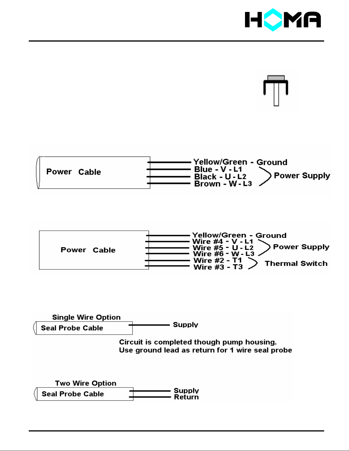
POWER LEAD WIRING
HOMA CH Series pumps may be provided with
1 or more cables, depending on motor
horsepower and operating voltage. Power leads
L1, L2, & L3 may be provided as single
conductor, or as two conductor. Two conductor
configuration may use leads from two separate
cables, or may use two conductors within one
cable. Please refer to wiring diagram in the
appendix for specific connection details. The
pump must be connected electrically through a
motor starter with proper circuit breaker
protection in order to validate warranty. Do not
splice cables.
THERMAL SWITCH WIRING :
Pumps are equipped with thermal switches
embedded in the stator windings which are
normally closed, automatically resetting
switches. Switches will open when the internal
temperature rises above the design temperature,
and will close when the temperature returns to
normal. Smaller CH pumps have internally
connected thermal switches. These units will
not have cable leads marked T1 & T3. Larger
CH pumps, and all Explosion Proof pumps will
have the thermal
switches configured for external control. Pumps
with external thermal switch connections must
be wired by a current regulated control circuit in
accordance with the NEC. Identify thermal
switch leads marked T1 and T3 in the power or
control cable. The resistance across these
leads will be .5O. These leads must be
connected to the thermal overload relay located
in the control panel. Thermal switch leads must
be connected to validate warranty.
SEAL PROBE WIRING (OPTIONAL)
The mechanical seal leak detector probe utilized
in the pump is a conductive probe which is
normally open. The intrusion of water into the
seal chamber completes the electrical circuit.
Control panel provisions will sense this circuit
closure, and will provide indication or alarm
functions depending on the panel design.
Either single or dual wire systems may be
provided. Single wire systems utilize one
energizing conductor, and the pump casing and
neutral lead as the ground or return portion of
the circuit. The dual wire systems utilize two
separate conductors for each leg of the circuit.
With either system, the seal probe leads must be
wired into a control circuit provided in the control
panel. This control circuit must energize the
probe with a regulated power source, and sense
the closed circuit in event of water intrusion.
Indication and alarm functions must also be
provided in the control circuit. Please see
control panel wiring diagram for seal probe
connection points. IMPORTANT: For
Hazardous Area Classification Pumps, leak
detector circuit must be in conformance with
applicable NEC codes and regulations.
START / RUN CAPACITORS AND RELAYS:
All single phase motors require start and/or run
capacitors to operate. Refer to the wiring
schematics in the appendix. Capacitors and
relays must be sized for the specific motor.
Please refer to nameplate for verification of
capacitor sizing.
Pg. 3
Installation, Operation & Maintenance Manual
Page 4

CH Series
MECHANICAL INSTALLATION:
PUMPS WITH AUTOCOUPLING
SYSTEMS
In the AutoCoupling installation mode the pump
is installed on a stationary component and
operates completely or partially submerged
(min. 8” above volute) in the pumping media.
The HOMA AutoCoupling kit base, guide claw
flange, upper guide rail bracket, profile seal and
base anchor bolts. Refer to dimensional drawing
for details.
For Threaded Discharge CH Series pumps,
attach the guide claw flange to the pump
discharge flange as follows:
1. Inspect threaded assemblies for damage.
2. Clean threaded portions of pump discharge
flange and guide claw flange.
3. Apply hardening thread sealer (for example
Loctite thread locker 242) to pump discharge
threads.
4. Thread guide claw flange on to pump
discharge fully. DISCHARGE THREADS ARE
NOT NPT. DO NOT OVER TIGHTEN.
5. Loosen guide claw flange full turn to expose
some threads.
6. Re-apply sealant on exposed threads .
7. Tighten guide claw flange until the claw is in
upright (horizontal) position.
For Flanged Discharge CH Series pumps, attach
the guide claw flange to the pump discharge
flange with the fasteners and gaskets
recommended in the accessory fastener
selection table. Use tightening torque’s indicated
in the table.
Install suitable lifting chain of an adequate size
and length to permit proper lowering and raising
of the pump. Lower the pump into the area
where it is required.
Install upper guide bar bracket as shown on
outline drawing located in the appendix. Do not
tighten mounting bolts completely at this point.
Properly locate the base anchor bolts into the
floor of the pump station Make sure when
Installation, Operation & Maintenance Manual
locating and securing the anchor bolts that the
base will align properly with the access cover at
the top elevation of the station.(Refer to outline
drawing in appendix). Place the base in position,
and level the base. If base is not level, proper
sealing of the pump to base will not occur!
Fully tighten all anchor and mounting bolts, and
verify that the profile seal is in position .
Place the guide rails in to the rings of the base
and cut them to a length that will allow the rails
to be secured at the top of the pump station with
the upper guide bar bracket and to extend down
to the sump floor. Loosen bracket mounting
bolts, install guide pipes into bracket and tighten
mounting bolts. For stations exceeding ten feet
in depth intermediate guide bar brackets are
recommended. One bracket is recommended for
each additional 10 feet of station depth.
Check that the guide system is properly installed
in the vertical orientation by using levels and a
plumb line. Connect the station riser piping to
the outlet flange of the base.
Before lowering the pump verify the direction of
impeller rotation (refer to start-up section for
procedure). Also it is recommended that the
stationary fitting be visible before lowering the
unit. If this is not possible, ensure all debris is
removed from wet well.
Make sure to use lifting equipment that has
adequate capacity for the pump that will be
handled. Before installing pump, check to be
certain the profile seal (rubber ring) is properly
positioned in the guide claw flange. Lift, then
position pump so the guides on the discharge
flange engage the rails. Slowly lower the pump
along the guide rail. Once the pump reaches its
bottom location it will automatically connect to
the base.
Pg. 4
Page 5
CH Series
INSTALLATION OF PUMPS WITH
RING STANDS:
The ring stand design allows for simple
economical installation or to be transportable
from one installation to another. It is intended to
operate completely or partially submerged in the
pumping liquid. Pump is designed to be installed
as a free standing unit.
Install the ring stand to the underside of the
volute with the supplied fasteners identified in
the accessory fastener selection table. Use
tightening torque’s indicated in the table.
Install suitable lifting chain of an adequate length
to ensure proper lowering and raising
capabilities. Lower the pump into the area where
it is required. Properly position power cable and
chain so they stay above pump and cannot enter
the pump suction.
START-UP
Prior To Applying Power
Prior to applying power to the pump; double
check all wiring and verify that the power
(Voltage, Phase) that will be supplied to the unit
matches the nameplate specified values.
Measure resistance of cable and pump motor
resistance of ground circuit between control
panel and outside of pump. Perform MEG ohm
check of motor insulation. Record all data on
start-up checklist which is included with this
manual.
Prior To Installation:
Before lowering the pump into position check the
direction of rotation. The impeller will rotate
clockwise as viewed from above, therefore the
pump will try to move in the counter clockwise
direction as the impeller rotates. "Bump the
Motor" by closing the pump circuit breaker and
push the pump start button and look for the
direction of movement specified above.
For three phase motors, if the starting jerk is in
the clockwise direction, open the circuit breaker
to isolate power and interchange two of the three
phase leads inside the control panel.
Wet Well Applications
If the above checks prove satisfactory the pump
is ready for operation. Lower the pump into
position . (Refer to Mechanical installation
section of this manual.)
Open discharge valve, and verify that all check
valves operate freely. It is very common for
discharge check valves to be jammed shut (or
open) after sitting for a period of time. Once all
valves are open and free, start the pump and
allow it to stabilize for several minutes prior to
recording any test data.
Listen for any unusual noise and be on the
lookout for unusual vibration This is generally
detectable on guide rails for AutoCoupling
installations and on discharge piping for ring
stand installations. Also for AutoCoupling
installations, look for any blow by from the
discharge connection.
Perform all remaining electrical , operational,
and performance tests specified on start-up
checklist. Record and provide details on the
checklist to validate warranty.
Pg. 5
Installation, Operation & Maintenance Manual
Page 6

CH Series
Installation / Startup Troubleshooting:
Only authorized service personnel who are
trained professionals shall troubleshoot and
repair pumps that are experiencing operational
or performance difficulties.
All HOMA pumps are factory tested, yet
startup difficulties can occur with any
mechanical equipment. Please note that our
technical support staff stands ready to assist
you with any problem or difficulty you might
encounter with our equipment.
The following is a tabulation of common
start-up problems and possible causes.
Symptom
Possible Causes
Pump will not start
1, 2, 3, 4, 27
Little or zero discharge
5, 6, 7, 8, 16
Insufficient discharge flow/pressure
5, 6, 9, 10, 11, 12, 26
Excessive power consumption
6, 9, 13
Excessive current draw
6, 13, 14, 15, 19
Excessive pump vibration/noise
12, 15, 16, 25, 26
Pumps runs & motor protection trips
17, 18, 19, 20, 21
Pumps runs manually, but not automatically
22, 23, 24
Pump runs hot
7, 19,
`
Listing of Possible Causes:
1. Incorrect or no power supplied to motor.
2. Power cable cut.
3. Short to ground in cable or motor winding.
4. Control panel circuit breaker open.
5. Actual system head is higher than
calculated or specified.
6. Incorrect impeller rotation direction.
7. Sump liquid level is below pump's minimum
submergence requirement.
8. Closed discharge valve or jammed check
valve.
9. Wear ring (s) worn. (If Applicable).
10. Vortex at pump's suction.
11. Discharge valve partially closed.
12. Insufficient NPSHA (Dry Pit Application).
13. Actual system head is lower than specified
resulting in over pumping condition.
14. Voltage supply to motor is lower than
required by motor.
15. Damaged bearings
16. High system head causing pump to operate
at extremely reduced capacity.
17. Object stuck inside impeller.
18. Motor not receiving proper voltage on all
three phases.
19. Phase/currents unbalanced or too high.
20. Insulation between phases and earth
ground,<1M-ohm.
21. Density of the pumping media too high.
22. Defective level sensor.
23. Hand/Off/Auto switch not in Auto Position.
24. Defective H/O/A switch , relay or contactor
coil.
25. Air Captured in Cooling Jacket
26. Pump not properly seated on AutoCoupling
27. Water intrusion through junction box
If you need additional help,
please call us at:
1 (800) 452 - HOMA
Pg. 6
Installation, Operation & Maintenance Manual
Page 7
CH Series
PREVENTIVE MAINTENANCE
Regular preventive maintenance will help ensure
longer pump life and more reliable operation. It is
recommended that pumps in intermittent
operation be inspected twice a year and pumps
in continuous operation be inspected every
1,000 hours. The following is a listing of required
inspection and maintenance items. (Refer to
shop manual for disassembly and reassembly
procedures).
If any of the problems described in the
following list exists stop operating the pump
to avoid damage or personal injury.
1. CABLE ENTRY
Make sure that the cable entry flange and strain
relief clamp are tight. If the cable entry is
showing signs of leakage remove cable from
entry, remove grommet, cut a piece of cable off
so that the grommet seats on a new portion of
the cable, replace grommet, and reinstall cable
assembly, into the top of the motor.
Note: Explosion Proof cables are sealed with a
Factory Mutual Approved potting compound.
Please consult factory for instruction.
2. CABLES
Inspect the cable for cuts, scrapes or sharp
bends. If the outer jacket is damaged, replace
the cable. Do not attempt splices within wetwells
3. MOTOR INSULATION RESISTANCE
Megger the insulation between the phases and
between any phase and ground. Resistance
values should be greater than 1 M ohm. If
abnormal readings are obtained contact
authorized service center immediately.
4. EXTERNAL PARTS ON PUMP
Make sure that all screws, bolts and nuts are
tight. Check the condition of pump lifting eyes
and replace if damaged or worn, Replace any
external part that appears worn or damaged.
5. SEAL CHAMBER OIL
Check the condition of the oil to see if any water
leakage has occurred. Remove the oil fill plug.
Drain the oil from the seal chamber into a
transparent container. Check for impurities and
emulsification.(Oil is cream-like.) If water
intrusion has occurred check lower mechanical
seal and replace if necessary. Refill seal
chamber with fresh oil. Refer to shop manual for
type and quantity of oil.
6. IMPELLER
Periodically inspect impeller by turning pump on
its side, remove suction strainer nuts and
strainer to expose impeller and inspect. Replace
the impeller if it is damaged or severely worn.
SPARE PARTS
In order to obtain spare parts identify the
required parts by looking at the enclosed cross
sectional drawing and listing, and contact
authorized HOMA PUMP TECHNOLOGY
representative with the parts required and the
pump serial number. Authentic Homa Pump
Technology parts shall be used to maintain
warranty.
Note: Explosion Proof pumps must be identified
as such, and the pump serial number must be
referenced for proper parts identification.
RECOMMENDED TOOLS AND
SUPPLIES
In addition to ordinary, standard tools, ensure
that complete set of metric socket wrenches,
complete set of Allen wrenches, metric triangular
wrench set, dead blow hammer, impeller puller,
Loctite 242 (Blue), petroleum jelly and anti- seize
compound are on hand.
Pg. 7
Installation, Operation & Maintenance Manual
Page 8
CH Series
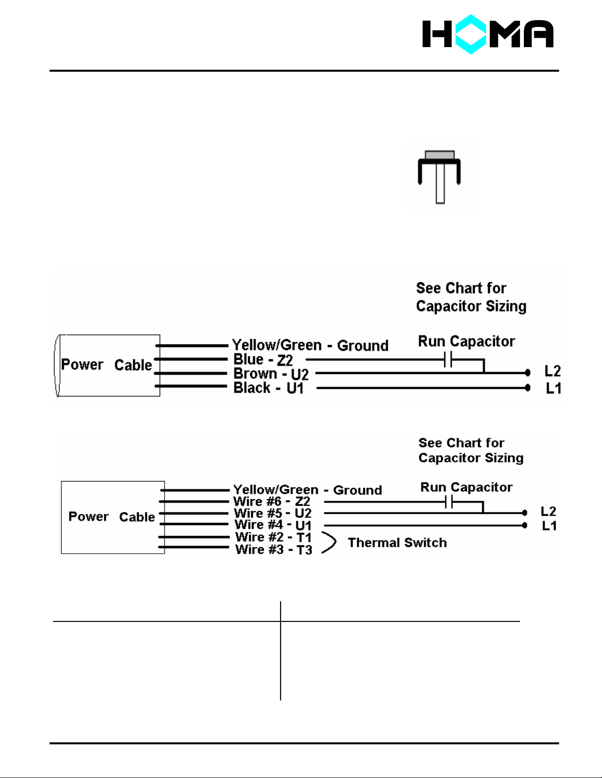
CH Series
CH Series (1.6 or 2.4 motors)
1 Phase Connection Diagram
Note: CH Pumps ( except XP) pumps have internally
wired thermal switches. These pumps use 4 conductor cable. Ground Lug - For auxiliary
grounding to earth or grounding grid.
4 Conductor Cable
7 Conductor Cable
Capacitor Sizing Chart
Pump Capacitor Pump Capacitor
Model Volts Capacitor PN# Model Volts Capacitor PN#
CH 406 115V 80uf @ 370V 8856080 H 306 115V 80uf @ 370V 8856080
CH 406 230V 25uf @ 370V 8856025 H 306 230V 25uf @ 370V 8856025
CH 412 115V 80uf @ 370V 8856080 H 312 115V 80uf @ 370V 8856080
CH 412 230V 25uf @ 370V 8856020 H 312 230V 25uf @ 370V 8856020
CH 411 115V 60uf @ 370V 8856080
CH 411 230V 20uf @ 370V 8856020
Note: See Three Phase connection diagram for seal probe wiring. Pg. 8
Installation, Operation & Maintenance Manual
Page 9
CH Series
CH Series
3 Phase Connection Diagram
Note: CH Series pumps( except XP) pumps that have internally
wired thermal switches use 4 conductor cable. Ground Lug - For auxiliary
grounding to earth or grounding grid.
4 Conductor Cable
7 Conductor Cable
Seal Probe Connections
Installation, Operation & Maintenance Manual
Pg. 10
Page 10

CH Series
START-UP REPORT
This report is designed to insure the customer that customer service and a quality product are the number one priorit y wit h Homa
Pump Technology Inc. Please answer the following questions completely and as accurately as possible. Mail this form to:
HOMA PUMP TECHNOLOGY INC.
390 BIRMINGHAM BOULEVARD
ANSONIA, CT 06401
ATTN: SERVICE MANAGER
Receipt of completed report will initiate operational warranty.
Reports that are not returned can delay or void warranty.
1.) Pump User's Name: ______________________________________________________________
Site Location: ___________________________________________________________________
Site Contract: _________________________________ __________________________________
Unit Supplied By: ________________________________________________________________
2.) Homa Pumps Model________________________ __________Serial No.____________________
Voltage____________ Phase_________________ H ertz____________ Horsepower__________
Method Used to Check Rotation (viewed from bottom) ___________________________________
Does Impeller Turn Freely By Hand: YES___________ NO _____________
3.) Condition of Equipment: EXCELLENT_____________ GOOD ____________ AVERAGE___________
Condition of Cable Jacket : EXCELLENT___________GOOD ____________ AVERAGE___________
Resistance of Cable and Pump Motor (measured at pump control)
U - V________________ Ohms V - W ________________Ohms U -W ________________Ohms
Resistance of Ground Circuit Between Control Panel and Outside of Pump______________Ohms
MEG Ohm Check of Insulation:
U to Ground _______________ V to Ground _______________ W to Ground ________________
4.) Condition of Equipment at Start-Up: Dry __________ Wet _____________ Mud dy______________
Was Equipment Stored:______________________ Length of Storage ______________________
Describe Station Layout ___________________________________________________________
5.) Liquid Level Controls: Model_________________ ____________ Type ______________________
Is Control Installed Away From Turbulence?____________________________________________
Operation Check : ( IF FLOAT SWITCHES SUPPLIED).
Tip lowest float (stop float), all pumps should remain off.
Tip second float (and stop float), one pump comes on
Tip third float (and stop float ), both pumps on (alarm on simplex).
Tip fourth float (and stop float), high level alarm on (omit on simplex ).
6.) Electrical Readings :
Single Phase:
Voltage Supply at Panel Line Connection, Pump Off, L1,L2 _______L2-L3______L3-L1__________
Voltage Supply at Panel Line Connection, Pump On,L1,L2 ________L2-L3_______ L3-L1____ __
Amperage: Load Connection, Pump On ,L1________________L2_______________L3__________
Three Phase:
Voltage Supply at Panel Line Connection, Pump Off, L1-L2_________ L2-L3 _______L3- L1______
Voltage Supply at Panel Line Connection, Pump On, L1-L2_________L2-L3________L-3-L1______
Amperage Load Connection, Pump On, L1___________ L2___________ L3_______________
Pg. 11
Installation, Operation & Maintenance Manual
Page 11

CH Series
7.) Final Check :
Is Pump Seated On Discharge Properly?______________Check For Leaks?_____________ ___
Does Check Valves Operate Properly ?_________________________ ___________________
Flow: Does Station Appear To Operate At Proper Rate__________________________________
Vibration Level :Measured ______________________ Observed__________________________
COMMENTS:___________________________________________________________________
8.) Equipment Difficulties During Start-Up:_______________________________________________
______________________________________________________________________________
___________________________________ ___________________________________________
___________________________________ ___________________________________________
9.) I Certify this Report to be accurate.
Authorized Homa Service Representative
___________________________________ ___________________________________________
(Signature)
DATE_______________________
Pump Station Owner/ Operator
___________________________________ ________________________________________
(Signature)
DATE _______________________
Form# CHIOM Rev. 2 07/03 Pg. 12
Installation, Operation & Maintenance Manual
 Loading...