

Page 1
Publication
Please Contact
Technical Support At 203
-
736-8890 With Any Additional Questions
Page
A Series Voltage Change
This procedure will provide you with step by step instructions to convert the operating voltage of dual
voltage 3 phase.
Tools Needed:
5 mm Allen Wrench
Wire Cutters
Wire Strippers
Terminal Crimp Tool
Qty 3–Crimpable Wire Nuts 14 to 16 Gage
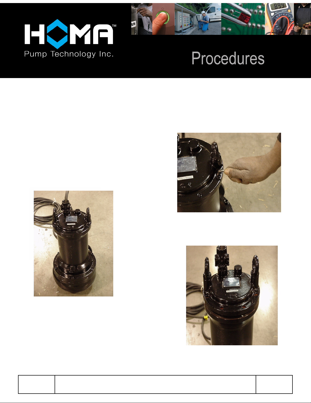
2. With pump in stable, upright position,
remove the eight 5mm capscrews as
indicated.
1. Remove pump from service. Disconnect
power supply. Clean and decontaminate
pump prior to working on it. See the pump
Installation, Operation, and Maintenance
Manual for detailed instructions.
88FN2040A
3. With the capscrews removed, lift the
motor cap off of the pump.
Please Be Prepared To Provide Pump Serial Number During Call
1 of 4
Page 2
Publication
Please Contact
Technical Support At 203
-
736-8890 With Any Additional Questions
Page
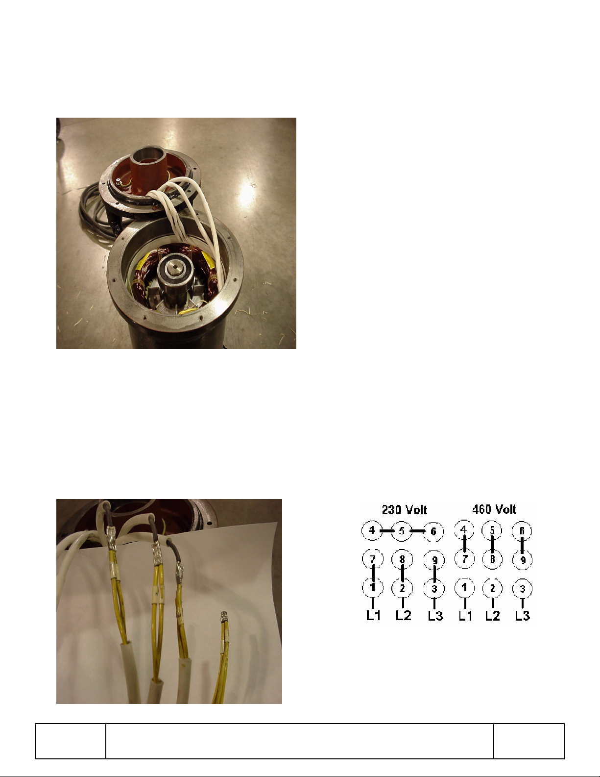
4. With motor cap removed, use a capscrew
that was removed from motor cap to
support motor cap as shown. Stator
windings and cable leads must be visible
and easy to reach. Your unit should now
look like this. Gently remove all wires
from around the stator windings. Take
care not to damage the winding
insulation. Do not use sharp tools!!
5. Separate the wire bundles as indicated,
and record the wire numbers in each
bundle.
If pump is wired for 208/230V, it will have 4
wire bundles. If pump is wired for 460V, it will
have 6 wire bundles.
Bundle 1 ___ ___ ___
Bundle 2 ___ ___ ___
Bundle 3 ___ ___ ___
Bundle 4 ___ ___ ___
Bundle 5 ___ ___ ___
Bundle 6 ___ ___ ___
Note: If the power cable is 4 lead, the wires
are color coded. If the power cable is 7 lead,
each individual wire will have a number on
cable sheath.
6. To convert from 230V to 460V operation,
you will need to separate the wire
bundles, one at a time, and reconnect as
indicated below.
88FN2040A
Please Be Prepared To Provide Pump Serial Number During Call
2 of 4
Page 3

Publication
Please Contact
Technical Support At 203
-
736-8890 With Any Additional Questions
Page
7. To perform the reconnection, locate the
wire bundle with wires 1, 7, and a power
lead. Cut wire number 7 from the bundle,
freeing individual wires. Strip wire
sheathing back ¼ in preparation for
reconnection.
8. Repeat procedure for wire bundle 2, 8,
and power
9. Repeat procedure for wire bundle 3, 9,
and power. Leave wire number 9 loose
for now.
Now you should have three new bundles
2 and power
3 and power
1 and power
along with 3 separate wires (#7,#8,#9), and
one bundle of 3 wires (#4,#5,#6).
10. Now, you will need to separate the wire
bundle numbers 4, 5, 6, and pair each
wire with the loose wires numbers 7, 8, 9
as indicated. Using the last three wire
connectors:
Join wire #4 to wire #7
Join wire #5 to wire #8
Join wire #6 to wire #9
11. At this point, you should have 6 separate
wire bundles, each with 2 wires. Wires
should be paired as follows: 4 to 7, 5 to 8,
6 to 9, number 1 to power, number 2 to
power and number 3 to power. See photo
Before proceeding, you should check the
resistance between all three cable leads
is the same. Resistance value is different
for the various size motors, so please
consult wiring handbook for specific
resistance values, if required.
88FN2040A
Please Be Prepared To Provide Pump Serial Number During Call
3 of 4
Page 4

Publication
Please Contact
Technical Support At 203
-
736-8890 With Any Additional Questions
Page
12. Starting with bundles 4-7, 5-8, 6-9, gently
tuck these 3 wire bundles behind the
windings on one side of stator. Then slide
insulation wrap back over wires then tuck
the remaining 3 bundles behind the
windings on the other side. Take care that
all wires are tucked in between stator
winding and housing. Also check that
white phase paper is in proper position,
and not extending above the stator
housing.
13. Verify that the large o ring is still in its
proper position on the pump housing.
Gently place motor cap back onto pump.
14. With motor cap back in position, then
align bolt holes and replace capscrews.
Tighten capscrews to 12 ft/lbs.
15. Pump should now be ready for installation
and operation at 460V. Be sure to record
that voltage has been changed in pump
service manual.
The pump is now ready for reassembly
88FN2040A
Please Be Prepared To Provide Pump Serial Number During Call
4 of 4
 Loading...