

Page 1

A Series
Installation, Operation
& Maintenance Manual
Project: _______________________
Installation: ____________________
Pump Model: ______________ Serial Number: ___________
AIOM REV. 6/12
HOMA Pump Technology, Inc.
390 Birmingham Boulevard Ansonia, CT 06401
Page 2
A Series
GENERAL INSTRUCTIONS:
This manual is intended to provide basic
installation and start-up guidance. It is to be read
and thoroughly studied prior to attempting to
install or operate any of the equipment supplied.
Equipment damage, which occurs by not
following these instructions will void the warranty.
SAFETY PRECAUTIONS:
Only trained qualified personnel shall be utilized
for installation and start-up.
The following is a general list of safety
precautions that should be followed when
installing, starting-up or servicing the pump.
The pump station owner or operator is
ultimately responsible for ensuring that all
equipment is installed, started up and
operated in a safe manner.
• Do not work alone.
• Double check to make sure that all lifting
equipment is in good working order and that
it has adequate lifting capacity for the weight
that it will handle.
• Wear safety helmet, goggles and protective
shoes, or appropriate safety materials
required.
• Before working on the pump make sure that
the power is disconnected and cannot be
energized by others. Lockout and tag the
control panel circuit breaker.
• Do not stand under suspended loads!
• Never enter or work within a wet well without
first checking to make sure sufficient oxygen
is present and that there are no explosive or
poisonous gases present.
• All personnel, who work with sewage
pumping equipment and systems shall be
vaccinated against diseases that can occur. If
there are any questions or doubts in this area
it is strongly suggested that the local health
agency be contacted.
• For Hazardous Area Classifications, only use
pumps with suitable Explosion Proof Rating.
Installation, Operation & Maintenance Manual
EQUIPMENT INVENTORY AND
INSPECTION:
Upon arrival of pump shipment carefully unpack
all components and compare with shipping and
purchase order documents to ensure that the
order is complete. Also inspect equipment for
any damage that might have occurred in
shipment. If any problems are detected contact
an authorized HOMA Pump Technology
Representative immediately.
TRANSPORTATION AND STORAGE
PROCEDURE:
Always lift the pump by its lifting bail or eye bolt.
Never lift the pump by its power cable!
Damage to Sealing ring or cable may result.
Pumps should be stored in an upright position,
taking extreme care to protect the power cable
and control cables from crushing, nicks or tears
which would permit water intrusion.
Power cable ends must be protected from
immersion in water as well as moisture intrusion.
The cable will wick water into the pump if it is not
protected properly. Power cable leads should be
covered with shrink tubing or suitable sealing
material during storage.
Short Term Storage: Short term storage is
defined as any time less than six months. We
recommend that pump and accessories be
stored in its original shipping container in a dry,
temperature controlled area. If climate controlled
storage is not possible, all exposed parts should
be inspected before storage and all surfaces that
have the paint scratched, damaged or worn
should be re-coated with air dry enamel paint.
The pump should be stored in an upright
position.
Long Term Storage: Any storage time
exceeding six months is considered long term. In
addition to the safeguards specified above, the
impeller should be rotated once a month to
prevent the mechanical seals and bearings from
being damaged, and the pump should be
inspected. The seal chamber oil should be
drained and replaced prior to commissioning.
The pump should be stored in an upright
position.
Pg. 2
Page 3

A Series
ELECTRICAL INSTALLATION:
GENERAL GUIDELINES
All electrical work shall be carried out under the
supervision of an authorized, licensed electrician.
The present state adopted edition of the
National Electrical Code as well as all local
codes and regulations shall be complied with.
VERIFICATION OF POWER SUPPLY
Prior to making any electrical connections or
applying power to the pump, compare the power
supply available at the pump station to the data
on the unit's nameplate. Confirm that both
voltage and phase match between pump and
control panel. The voltage supplied at the pump
shall be +5 / -10% of the nameplate value,
frequency shall be + / - 1% of the nameplate
value, the voltage phase balance shall be within
1% and the maximum corrected power factor
shall be 1.0.
POWER LEAD WIRING
HOMA A Series pumps may be provided with 1
or more cables, depending on motor horsepower
and operating voltage. Power leads L1, L2, & L3
may be provided as single conductor, or as
multiple conductors. Multiple conductor
configurations may use leads from separate
cables, or may use two conductors within one
cable. Please refer to enclosed wiring diagram
for specific connection details. The pump must
be connected electrically through a motor starter
with proper circuit breaker protection in order to
validate warranty. Do not splice cables.
THERMAL SWITCH WIRING :
Pumps are equipped with thermal switches
embedded in the stator windings which are
normally closed, automatically resetting switches.
Switches will open when the internal temperature
rises above the design temperature, and will
close when the temperature returns to normal.
Thermal switches must be wired to a current
regulated control circuit in accordance with the
NEC.
Identify thermal switch leads marked T1 and T3
in the power or control cable.
The resistance across the leads will be .5 Ohms.
Thermal leads must be connected to the thermal
overload relay located in the control panel.
Thermal switch leads must be connected to
validate warranty.
Note: All sizes of Class 1, Div. 1 pumps
for hazardous service must have thermal
switch leads connected to a current
regulated control circuit in accordance
with NEC.
SEAL PROBE WIRING
The mechanical seal leak detector probe utilized
in the pump is a conductive probe which is
normally open. The intrusion of water into the
seal chamber completes the electrical circuit.
Control panel provisions will sense this circuit
closure, and will provide indication or alarm
functions depending on the panel design.
Either single or dual wire systems may be
provided. Single wire systems utilize one
energizing conductor, and the pump casing and
neutral lead as the ground or return portion of the
circuit. The dual wire systems utilize two
separate conductors for each leg of the circuit.
With either system, the seal probe leads must be
wired into a control circuit provided in the control
panel. This control circuit must energize the
probe with a regulated power source, and sense
the closed circuit in event of water intrusion.
Indication and alarm functions must also be
provided in the control circuit. Please see control
panel wiring diagram for seal probe connection
points. IMPORTANT: For Hazardous Area
Classification Pumps, leak detector circuit must
be in conformance with applicable NEC codes
and regulations.
START / RUN CAPACITORS AND RELAYS:
All single phase motors require start and run
capacitors along with a start relay to operate.
Refer to the enclosed wiring diagram.
Capacitors and relays must be sized for the
specific motor.
Capacitors are sized based on reference voltage.
The run capacitor may need to be resized to
match the available field voltage. Each cap kit
shipped is supplied with a wiring diagram and
start up procedure.
Pg. 3
Installation, Operation & Maintenance Manual
Page 4
A Series
Variable Frequency Drives:
Special considerations must be taken when
operating pumps with variable frequency
drives (inverters). The inverter circuit design,
horsepower required by pump, motor cooling
system, power cable length, operating voltage,
and anticipated turndown ratio must be fully
evaluated during the design stage of the
installation.
As a minimum, properly sized load reactors
and filters must be installed between the
inverter and the pump to protect the pump
motor from damaging voltage spikes.
Warranty coverage will not be provided on any
pump motor that is operated with a variable
frequency drive, unless the load side of the
inverter is properly isolated from the pump.
ADDITIONAL PUMP PROTECTIVE
DEVICES
Several optional pump protection devices are
available to protect submersible motors from
damage, and may be provided in your pump.
Temperature Sensing RTD*: PT100 sensors
are available in two critical locations on larger
machines, the lower bearings and motor
windings. N.C. Circuit - 108 ohm
Moisture Sensors:
seal chamber probe, additional sensors may be
installed in the stator winding, motor cap, or
junction box. These sensors may be either one of
the following:
Moisture Detectors*: These are micro
float switches designed to detect small amounts
of liquid. These are available in the stator
housing of 50hp and larger size pumps.
N.C. Circuit - 268 ohm
Leakage Detectors*: These normally
open, single or 2 wire probes are used to detect
the presence of water in the pump. Single wire
probes use the pump ground to complete
circuit.
* HOMA Go Switch or approved equivalent relay
is required for sensor operation.
In addition to the standard
Installation, Operation & Maintenance Manual
MECHANICAL INSTALLATION:
PUMPS WITH AUTOCOUPLING
SYSTEMS
The HOMA Auto-Coupling is a quick removal
system used to prevent personnel from needing
to enter the wet well.
The HOMA Auto-Coupling kit consists of a base,
guide claw flange, upper guide rail bracket,
profile seal and base anchor bolts. Refer to
“Auto-Coupling Parts ID” technical page on
website.
For all A Series pumps, attach the guide claw
flange to the pump discharge flange with the
fasteners and gaskets included with the autocoupling kit. Use tightening torques indicated in
the table on pg. 6. Do not over tighten!
Install the profile gasket (if not already installed
at the factory) into the guide claw with the large
diameter fitted into the groove inside the claw.
Refer to the attached instructional sheet for
proper profile gasket installation.
Install suitable lifting chain of an adequate size
and length to permit proper lowering and raising
of the pump.
Properly locate the base, and with suitably sized
anchor bolts, fasten it to the floor of the pump
station. Make sure when locating and securing
the anchor bolts that the base will align properly
with the access cover at the top elevation of the
station. Place the base in position, and level the
base.
If the base is not level, proper sealing of the
pump to base may not occur!
Pg. 4
Page 5
A Series
Place the guide rails (supplied by others), cut to
length into the rings of the base. The rails will be
secured at the top of the pump station with the
upper guide bar bracket and extend down to the
sump floor.
Install the upper guide bar bracket to maintain
vertical orientation of the guide rails.
For stations exceeding 10 feet in depth
intermediate guide bar brackets are
recommended. One bracket is recommended for
each additional 10 feet of station depth.
Check that the guide system is properly installed
in the vertical orientation by using levels and a
plumb line. Fully tighten all anchors and
mounting bolts.
Connect the station riser piping to the outlet
flange of the base.
Before lowering the pump, verify the direction of
impeller rotation (refer to technical details section
for procedure).
Make sure to use lifting equipment that has
adequate capacity for the pump that will be
handled. Before installing pump, check to be
certain the profile seal (rubber ring) is properly
positioned in the guide claw flange. Then
position pump so the guides on the discharge
flange engage the rails. Slowly lower the pump
along the guide rail. Once the pump reaches its
bottom location it will automatically connect to
the base.
It is recommended that the stationary base elbow
be visible before lowering the unit. If this is not
possible, ensure all debris is removed from wet
well.
Important: Do not install more than one (1) check
valve into any piping system or problems will
occur.
Minimum Submergence
For optimal cooling, motor should be completely
submerged at all times. In pump-down systems,
level should not fall below one discharge
diameter above the top of the volute. For
continuous operation with a VFD, level should
not be maintained below the top of the motor for
sustained periods. For specific inquiries, please
contact factory for assistance.
Installation, Operation & Maintenance Manual
INSTALLATION OF PUMPS WITH RING
STANDS:
The ring stand design allows for a free standing,
simple economical installation or to be
transportable from one installation to another.
It is intended to operate completely or partially
submerged in the pumping liquid.
Install the ring stand to the underside of the
volute with the supplied fasteners provided.
Apply thread locking compound such as blue
#242 and tighten the bolts using the torque table
indicated in the table. Do not over tighten!
Install suitable lifting device of an adequate
length to ensure proper lowering and raising
capabilities. Lower the pump into the area where
it is required. Properly position power cable and
chain so they stay above pump and cannot enter
the pump suction.
INSTALLATION OF PUMPS FOR DRY
PIT APPLICATIONS:
Foundation and Piping Requirements:
General
The following recommendations are basic
guidelines which are intended to outline basic
requirements in the design of the dry pit station.
It is essential that a licensed professional
engineer be retained by the owner to design the
station and all support structures.
Foundations
Foundations may consist of any structure heavy
enough to provide permanent rigid support for
the pump and inlet elbow stand. HI standards
demand at least 5 times the weight of the pump.
Concrete foundations built up from the solid
ground are the most commonly used. The
concrete floor shall be level. The space required
by the inlet stand and the location of the
foundation anchor bolts are shown on the outline
dimension drawing. Foundation bolts are to be
embedded in the concrete.
Pg. 5
Page 6
A Series
Suction Piping
Suction piping should be at least as large as the
pump inlet elbow suction. If reducers are utilized
they should be of the eccentric, conical type and
must be installed with the level side up. Suction
piping should be run as straight as possible with
a recommended 10 suction diameter distance
before pump inlet. Rough sections in pipe suction
line can cause turbulence and result in severe
vibration of the pump. Pipe reducers should not
be installed adjacent to pump inlet
All pipe flange joints should be gasketed to
prevent air from entering the pipe. High points
that may collect vapor are to be avoided.
Isolation valves such as gate valves can be
installed in order to facilitate the removal of the
pump for maintenance. Any valve installed in the
suction line should be installed with the stems
horizontal.
The location of the suction piping termination
point inside of the wet pit must be installed such
that sufficient submergence is obtained to
prevent vortexing. Invert location and multiple
suction points can cause hydraulic instability to
an operating pump. Avoid high velocity or
turbulence at suction pipe inlet.
Discharge Piping
A check valve and isolation valve shall be
installed in the discharge line. The check valve
should be installed between the pump discharge
flange and the isolation valve. If pipe increasers
are used on the discharge line, they should be
placed between the check valve and the pump.
The inlet elbow stand allows the pump to be
installed in a stationary position in a dry pit. Place
the inlet stand in position and tighten the anchor
nuts.
Lower the pump onto the top flange of the
inlet stand. DO NOT ALLOW SLACK ON THE
LIFTING CABLE UNTIL THE PUMP IS
BOLTED DOWN. Make sure the flange bolt
holes align with the mounting holes on the
underside of the volute. Secure the pump to the
mounting flange with the fasteners that are
specified in the accessory fastener selection
table below.
Installation, Operation & Maintenance Manual
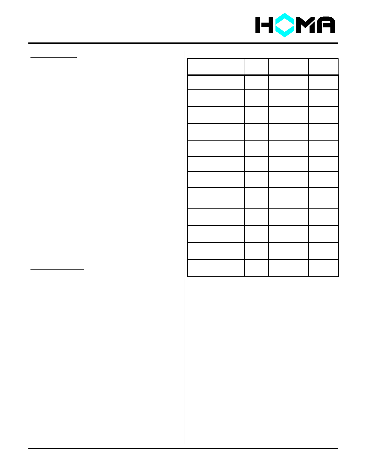
Bolts
PUMP MODEL Anchors
3” A SERIES
AUTOCOUPLING
4” A-SERIES
AUTOCOUPLING
3” & 4” A-SERIES
RING STAND
3” & 4” A- SERIES
DRY SUMP
6” A-SERIES
AUTOCOUPLING
6" A-SERIES
RING STAND
6" A-SERIES
DRY SUMP (1 Piece)
6" A-SERIES
DRY SUMP
(N/PMotor)
6" A-SERIES
DRY SUMP (F Motor)
8” A-SERIES
AUTOCOUPLING
8" A-SERIES
RING STAND
8" A-SERIES
DRY SUMP (2 Piece)
Notes:
1. For pumps larger than 8” please consult
factory.
2. Flange bolts must be tightened in cross
pattern to avoid damage to the raise face
flanges.
3. Standard Flange Bolts are 316SS
4. Standard Anchors are Plated Steel
5. Autocoupling systems include qty 4 M12
anchors for the upper bracket. Torque to 38
ft#.
6. Anchor bolt holes should be drilled to the
actual diameter of the anchor (M12 anchor
requires 12mm diameter hole).
8 M16X60mm 108 ft/ #
4 M16 74 ft/ #
8 M16X60mm 108 ft/ #
4 M16 74 ft/ #
4 M16x25mm 108 ft/#
8 M16x40mm 108 ft/#
4 M16 74 ft/#
8 M20x70mm 150 ft/#
4 M16 74 ft/#
4 M20x40mm 150 ft/#
8 M20x45mm 150 ft/#
4 M16 74 ft/#
8 M20x65mm 150 ft/#
4 M16 74 ft/#
8 M20x70mm 150 ft/#
4 M16 74 ft/#
8 M20x70mm 150 ft/#
4 M20 150 ft/#
4 M20x30mm 150 ft/#
8 M20x75mm 150 ft/#
4 M20 150 ft/#
SIZE TORQUE
Pg. 6
Page 7

A Series
Installation / Startup Troubleshooting:
Only authorized service personnel who are
trained professionals shall troubleshoot and
repair pumps that are experiencing operational or
performance difficulties.
All HOMA pumps are factory tested, yet
startup difficulties can occur with any
mechanical equipment. Please note that our
technical support staff stands ready to assist
you with any problem or difficulty you might
encounter with our equipment.
The following is a tabulation of common
start-up problems and possible causes.
Symptom
Possible Causes
Pump will not start
1, 2, 3, 4, 27, 28, 29, 31, 32
Little or zero discharge
5, 6, 7, 8, 16, 30, 32
Insufficient discharge flow/pressure
5, 6, 9, 10, 11, 12, 26, 30
Excessive power consumption
6, 9, 13, 28, 30
Excessive current draw
6, 13, 14, 15, 19, 26, 30
Excessive pump vibration/noise
12, 15, 16, 25, 26, 28, 31
Pump runs & motor protection trips
17, 18, 19, 20, 21, 28
Pump runs manually, but not automatically
22, 23, 24
Pump runs hot
7, 19, 25, 26, 28
Installation, Operation & Maintenance Manual
Listing of Possible Causes:
1. Incorrect or no power supplied to motor.
2. Power cable cut.
3. Short to ground in cable or motor winding.
4. Control panel circuit breaker open.
5. Actual system head is higher than
calculated or specified.
6. Incorrect impeller rotation direction.
7. Sump liquid level is below pump's minimum
submergence requirement.
8. Closed discharge valve or jammed check
valve.
9. Wear ring worn. (If Applicable).
10. Vortex at pump's suction.
11. Discharge valve partially closed.
12. Insufficient NPSHA (Dry Pit Application).
13. Actual system head is lower than specified
resulting in over pumping condition.
14. Voltage supply to motor is lower than
required by motor.
15. Damaged bearings.
16. High system head causing pump to operate
at extremely reduced capacity.
17. Object stuck inside impeller.
18. Motor not receiving proper voltage on all
three phases.
19. Phase/currents unbalanced or too high.
20. Insulation between phases and earth
ground, <1M-ohm.
21. Density of the pumping media too high.
22. Defective level sensor.
23. Hand/Off/Auto switch not in Auto Position.
24. Defective H/O/A switch, relay or contactor
coil.
25. Air Captured in Cooling Jacket.
26. Pump not properly seated on Auto
Coupling.
27. Water intrusion through junction box.
28. VFD or Soft Start not functioning properly.
29. Run capacitor size too large (1ph).
30. Start capacitor size too small (1ph).
31. Profile seal not sealing or missing.
32. Start relay or capacitor damaged (1ph).
Please note that some possible causes may not
relate to your particular model.
If you need additional help, please
contact your local distributor or e-mail
service@ homapump.com
Pg. 7
Page 8

A Series
MAINTENANCE
Regular maintenance will help ensure longer
pump life and more reliable operation. It is
recommended that pumps in intermittent
operation be inspected twice a year and pumps
in continuous operation be inspected every 1,000
hours. The following is a listing of required
inspection and maintenance items.
If any of the problems described in the
following list exists stop operating the pump
to avoid damage or personal injury.
1. CABLE ENTRY
Make sure that the cable entry flange and strain
relief clamp are tight. If the cable entry is
showing signs of leakage remove cable from
entry, remove grommet, cut a piece of cable off
so that the grommet seats on a new portion of
the cable, replace grommet, and reinstall cable
assembly, into the top of the motor.
Note: Explosion Proof cables are sealed with a
Factory Mutual Approved potting compound.
Please consult factory for instruction.
2. CABLES
Inspect the cable for cuts, scrapes or sharp
bends. If the outer jacket is damaged, replace
the cable. Splices of the power or control cable
within the wet well area are not acceptable.
3. MOTOR INSULATION RESISTANCE
Megger the insulation between the phases; and
between any phase and ground. Resistance
values should be greater than 1 M ohm. If
abnormal readings are obtained, contact
authorized service center immediately.
4. EXTERNAL PARTS ON PUMP
Make sure that all screws, bolts and nuts are
tight. Check the condition of pump lifting eyes
and replace if damaged or worn, Replace any
external part that appears worn or damaged.
Installation, Operation & Maintenance Manual
5. SEAL CHAMBER OIL
Note: Use extreme care when removing the seal
chamber plug, as the chamber may become
pressurized if seal failure has occurred. Seal
chamber oil should be checked for signs of water
intrusion, or other impurities any time the pump is
removed from wet well. To check the condition
of the oil, remove the oil fill plug. Drain the
chamber volume into a transparent container.
Visually check sample for impurities or
emulsification (oil may appear cream-like if a
small amount of water is present). If significant
water intrusion has occurred, remove and
replace lower mechanical seal. Unless obvious
mechanical damage has occurred to the lower
seal, it is good practice to replace the upper and
lower mechanical seals as a set. Refill seal
chamber with fresh oil to the bottom of fill plug
port (when pump is in vertical position) and
replace oil fill plug.
6. IMPELLER
Periodically inspect impeller by turning pump on
its side, remove suction strainer nuts and strainer
to expose impeller and relocate position of
adjusting plate (suction cover) as needed.
Replace the impeller if it is damaged or worn.
SPARE PARTS
In order to obtain spare parts identify the
required parts by looking at the enclosed cross
sectional drawing and listing, and contact
authorized HOMA PUMP TECHNOLOGY
representative with your order. Authentic Homa
Pump Technology parts shall be used to
maintain warranty.
Note: Explosion Proof pumps must be identified
as such, and the pump serial number must be
referenced for proper parts identification.
RECOMMENDED TOOLS AND
SUPPLIES
In addition to ordinary maintenance and lifting
devices, ensure that complete set of metric Allen
wrenches, impeller puller, Loctite 242 (Blue), and
Anti-seize compound are on hand.
Pg. 8
Page 9

A Series
Wire Markings of Power & Control Cables
Wire Marker Wire Connection Normal Value
Power Cable (s)
L3 Power Supply See Enclosed Wiring Diagram
L2 Power Supply See Enclosed Wiring Diagram
L1 Power Supply See Enclosed Wiring Diagram
Yellow/Green - Ground
Control Cable (s)
T1 Thermal Switch N.C. .4 ohm
T2 or T3 Thermal Switch N.C. .4 ohm
K1 Thermistor (optional) N.C. 268 ohm
K2 Thermistor (optional) N.C. 268 ohm
P1 Lower Bearing Temp. PT100 N.C. 108 ohm
P2 Lower Bearing Temp. PT100 N.C. 108 ohm
P3 Lower Bearing Temp. PT100 N.C. 108 ohm
P4 Lower Bearing Temp. PT100 N.C. 108 ohm
S1* Oil Chamber Seal Probe 1 or 2 wire probe N.O.
S2 Oil Chamber Seal Probe 2 wire probe N.O.
S3 Connection Chamber Seal Probe 2 wire probe N.O.
S4 Connection Chamber Seal Probe 2 wire probe N.O.
S5* Stator Housing Leak Detector 1 wire probe N.O.
S7 Stator Housing Leak Detector Level Switch N.C. .7 ohm
S8 Stator Housing Leak Detector Level Switch N.C. .7 ohm
Yellow/Green –Ground - *Must be used to complete 1 wire probe circuits!
Note: Pump may have single or multiple power or control cables. Verify all
wire connections are correct before applying power to any circuit. Improper
power supply can permanently damage certain control devices.
All control or monitoring devices must be connected to a suitable power
supply and sensing device. Homa can provide an optional Go Switch for
any of these control or monitoring devices. Consult your local Homa
distributor
Pg. 9
Installation, Operation & Maintenance Manual
Page 10

A Series
PROFILE SEAL INSTALLATION
When installing a profile seal, one side of the seal has a larger diameter ridge on the
outside edge. This side goes to the inside of the guide claw as seen below.
Press the seal into its seat starting on one side and work the rest of the seal into the
same position. When finished, it should look as below.
When properly installed, the profile seal will stay in place when pulled straight outwards.
It is recommended that 3M Weather Stripping be applied to the surface touching the
claw if possible for added adhesion.
REMEMBER:
Pg. 10
the larger diameter always goes to the inside.
Installation, Operation & Maintenance Manual
Page 11

A Series
Single Phase Pump Start-Up Procedure
Run Capacitor sizing can vary depending on the incoming supply voltage provided. HOMA Single Phase
pumps are provided with Start and Run Capacitor(s) sized for 220-230V under load. Frequently, the
available line voltage is considerably different than indicated, and the Run capacitor(s) may need to be
resized to match the available field voltage. The following procedure will allow you to verify proper
operation of your single phase pump, and/or make necessary changes to your capacitors to correct for
your power supply.
After verifying wiring is in accordance with your pump requirements, start pump and record the following
readings from each of the (3) pump cable leads.
Current under load:
U1 _________
Should be (highest reading) (middle reading) (lowest reading)
Lead U1 (common) should have the highest current reading. Lead Z2 (start) should have the lowest
reading.
If Z2 current draw is greater than the current draw of either U1 or U2, a smaller size Run capacitor (lower
microfarad rating) is required to correct the condition. Example: If a 60 µf Run capacitor was supplied,
change to a 50 µf Run capacitor and check current readings. Typically, only one step down in capacitor
size is required, but in certain instances 2 steps may be required.
Amps
,> U2 __________
Amps
,> Z2 __________
Amps
( ) The standard capacitor kit provided includes: ____________µf start capacitor
____________µf run capacitor.
( ) Additional run capacitors have been included for use in tuning the pump to match available line
voltages for optimum performance.
___________µf run capacitor
___________µf run capacitor
___________µf run capacitor
This form is provided for your use in optimizing the performance and service life of your single phase
pumps, and is applicable to most Capacitor Start/Capacitor Run motors. Please contact our Technical
Service Department @ (203)-736-8890 with any questions or if you require any additional information or
assistance.
Installation, Operation & Maintenance Manual
Pg. 11
Page 12

A Series
N Motor Capacitor Sizing Chart
Pump Model Start Capacitor Run Capacitor Cap Kits
AMX334-434/1-142/2.9N 80µf @ 330V 40µf @ 370V 8857010
AMX334-434/1-155/4N 100µf @ 330V 50µf @ 370V 8857035
AMX334-434/1-178/4N 100µf @ 330V 50µf @ 370V 8857035
AMX334-434/1-184/5N 150µf @ 330V 80µf @ 370V 8857040
AMX334-434/1-193/5N 150µf @ 330V 80µf @ 370V 8857040
AMX334-434/1-193/7N 150µf @ 330V 100µf @ 370V† 8857045
AMX334-434/1-206/7N 150µf @ 330V 100µf @ 370V† 8857045
AMX334-434/1-206/10N 250µf @ 330V** 120µf @ 370V* 8857055
AMX334-434/1-218/10N 250µf @ 330V** 120µf @ 370V* 8857055
AMX334-434/1-228/10N 250µf @ 330V** 120µf @ 370V* 8857055
†(2) 50µf run capacitors in parallel are required.
*Consult factory for A Frame motors with centrifugal switch.
* (2) 60µf run capacitors in parallel are required.
** (1) 150µf & 100µf start capacitor in parallel required.
External Seal Probe Wiring
Seal Probes must be connected to a Homa Go Switch or suitable controller to operate.
Pg.12
Installation, Operation & Maintenance Manual
Page 13

A Series
C, D & T Motor Capacitor Sizing Chart
Pump Model Start Capacitor Run Capacitor Cap Kits
AMX334-434/1-1422/C/C 80µf @ 330V 40µf @ 370V 8807010
AMX334-434/1-142/2.5D 80µf @ 330V 50µf @ 370V 8857060
AMX334-434/1-142/2.9T/C 60µf @ 330V 40µf @ 370V 8857065
AMX334-434/1-155/3.6D 80µf @ 330V 50µf @ 370V 8857060
AMX334-434/1-155/4.3T/C 100µf @ 330V 50µf @ 370V 8857035
AMX334-434/1-155/5.1T/C 100µf @ 330V 50µf @ 370V 8857035
AMX334-434/1-178/3.6D 80µf @ 330V 50µf @ 370V 8857060
AMX334-434/1-178/4.3T/C 100µf @ 330V 50µf @ 370V 8857035
AMX334-434/1-178/5.1T/C 100µf @ 330V 50µf @ 370V 8857035
AMX334-434/1-184/5.1T/C 100µf @ 330V 50µf @ 370V 8857035
AMX334-434/1-193/5.1T/C 100µf @ 330V 50µf @ 370V 8857035
AMX334-434/1-193/6.7T/C 120µf @ 330V 60µf @ 370V 8857070
AMX334-434/1-206/6.7T/C 120µf @ 330V 60µf @ 370V 8857070
AMX334-434/1-206/9.7T/C 150µf @ 330V 80µf @ 370V 8857075
AMX334-434/1-218/9.7T/C 150µf @ 330V 80µf @ 370V 8857075
AMX334-434/1-228/9.7T/C 150µf @ 330V 80µf @ 370V 8857075
AMX334-434/1-228/11.4T/C 250µf @ 330V** 120µf @ 370V* 8857080
AMX334-434/1-235/11.4T/C 250µf @ 330V** 120µf @ 370V* 8857080
AMX334-434/1-250/11.4T/C 250µf @ 330V** 120µf @ 370V* 8857080
*Consult factory for A Frame motors with centrifugal switch.
* (2) 60µf run capacitors in parallel are required.
** (1) 150µf & 100µf start capacitor in parallel required.
External Seal Probe Wiring
Seal Probes must be connected to a Homa Go Switch or suitable controller to operate.
Installation, Operation & Maintenance Manual
Pg.13
Page 14

A Series
START-UP REPORT
To validate warranty, please answer the following questions during start-up as completely and as accurately as
possible and mail this form to:
HOMA PUMP TECHNOLOGY INC.
390 BIRMINGHAM BOULEVARD
ANSONIA, CT 06401
ATTN: SERVICE MANAGER
Receipt of completed report will initiate operational warranty.
Reports that are not returned can delay or void warranty.
1.) Pump User's Name: _____________________________________________________________
Site Location: __________________________________________________________________
Site Contract: __________________________________________________________________
Unit Supplied By: _______________________________________________________________
2.) HOMA Pumps Model__________________________________ Serial No._____________________
Voltage____________ Phase_________________ Hertz________________ Horsepower________
Method Used to Check Rotation (viewed from bottom) __________________________________
Does Impeller Turn Freely By Hand: YES________ NO _________
3.) Condition of Equipment: EXCELLENT_____________ GOOD ____________ AVERAGE___________
Condition of Cable Jacket : EXCELLENT___________GOOD ____________ AVERAGE___________
Resistance of Cable and Pump Motor (measured at pump control)
1 Phase: U1 – U2 _________ Ohms; U1 - Z2 ________ Ohms; U2 – Z2 _________ Ohms; T1 – T2 ________Ohms
3 Phase: U - V_____________ Ohms; V - W ____________Ohms; U -W _________Ohms, T1 – T2 ________ Ohms
Resistance of Ground Circuit Between Control Panel and Outside of Pump __________Ohms
MEG Ohm Check of Insulation:
U to Ground _______________ V to Ground _______________ W to Ground____________
4.) Condition of Equipment at Start-Up: Dry __________ Wet _____________ Muddy_________
Was Equipment Stored:_______________ Length of Storage ________________________
Describe Station Layout ___________________________________________________________
5.) Liquid Level Controls: Model_____________________________ Type ______________________
Is Control Installed Away From Turbulence?____________________________________________
Operation Check: (IF FLOAT SWITCHES SUPPLIED).
Tip lowest float (stop float), all pumps should remain off.
Tip second float (and stop float), one pump comes on.
Tip third float (and stop float), both pumps on (alarm on simplex).
Tip fourth float (and stop float), high level alarm on (omit on simplex).
6.) Electrical Readings:
Single Phase:
Voltage Supply at Panel Line Connection, Pump Off, L1- L2 _______ L1-Ground ______ L2-Ground _________
Voltage Supply at Panel Line Connection, Pump On, L1- L2 ________ L1-Ground _______ L2-Ground ________
Amperage: Load Connection, Pump On, U1________________ U2 _______________ Z2 _________
Resistance Across Thermal Switch leads T1-T2 _______ ohms
Three Phase:
Voltage Supply at Panel Line Connection, Pump Off, L1-L2_________ L2-L3 _______ L3-L1 ______
Voltage Supply at Panel Line Connection, Pump On, L1-L2_________ L2-L3 _______ L3-L1 ______
Amperage Load Connection, Pump On, L1_____________ L2_____________ L3_______________
Resistance Across Thermal Switch leads T1-T2 _______ ohms
Pg. 14
Installation, Operation & Maintenance Manual
Page 15

A Series
7.) S
tarting Devices
Are pumps being started DOL, or with Soft Start device. Indicate manufacturer of Soft Starter. ___________
Are any vibrations evident while pump is being controller by the soft starter? __________________________
Are pumps being operated with VFD (Variable Frequency Drive)? _______
Please indicate brand and model VFD: _________________________________________________________
Are load reactors being used between VFD output and pump? ______ Please indicate size _______________
What ramp up and decel time is the VFD set for? Accel __________ seconds, Decel: _________ seconds
What is the minimum frequency the pump can operate at in this system? ______Hz. Is low speed limit set?_______
8.) Final Check:
Are Thermal Switches properly wired? _______What Over-temperature Relay is being used? ____________
Is Pump Seated On Discharge Properly? ______________ Check For Leaks? __________________
Does Check Valve Operate Properly? ________________________________________________
Flow: Does Station Appear To Operate At Proper Rate ___________________________________
Vibration Level: Measured _____________________ Observed_____________________________
Has the cooling jacket been vented? _________ Is a permanent cooling jacket vent installed? _______
COMMENTS: _____________________________________________________________________
9.) Equipment Difficulties During Start-Up:_________________________________________________
________________________________________________________________________________
________________________________________________________________________________
________________________________________________________________________________
10.) I Certify this Report to be accurate.
Authorized Homa Service Representative:
___________________________________________________________ Phone #____________________
(Signature)
DATE_______________________
Pump Station Owner/ Operator
___________________________________________________________ Phone # ____________________
(Signature)
DATE _______________________
Pg. 15
Installation, Operation & Maintenance Manual
Page 16

A Series
230 #
A Series Technical Details
The following is offered as a general guide to values and capacities commonly used.
Resistance Readings (ohms) Pump Weight
230V 230V 460V
HP / RPM
2.5HP-1750 D 2.2 5.0 1.5 5.0
2.8HP-1160 T N/A 2.7 5.0 230 #
2.9HP-1750 N 2.2 5.0 3.1 11.0 230 #
2.9HP-1750 T 1.6 4.4 3.1 11.0 230 #
3.5HP-1750 D N/A 1.9 5.5 230 #
3.8HP-1160 T N/A 1.5 2.5 240 #
4.3HP-1750 N 1.5 3.0 1.5 4.2 240 #
4.3HP-1750 T 1.5 4.2 240 #
5.1HP-1750 T 1.1 2.6 N/A N/A 250 #
5.5HP-1750 N 0.9 1.9 1.3 3.7 250 #
5.5HP-1750 T N/A 1.3 3.7 250 #
6.2HP-1160 T N/A 1.3 3.7 250 #
6.7HP-1750 T 0.7 1.9 N/A N/A 260 #
7.5HP-1750 N 0.8 1.5 0.9 2.6 260 #
7.5HP-1750 T N/A 1.2 3.0 260 #
8.3HP-1160 T N/A 0.9 2.6 260 #
9.7HP-1750 T 0.5 1.4 N/A N/A 260 #
9.8HP-1160 P N/A 0.7 2.2 290 #
10HP-1750 N 0.3 0.9 0.6 1.9 290 #
10HP-1750 T N/A 0.6 1.9 290 #
11.4HP-1750 T 0.4 0.8 N/A N/A 290 #
13HP-1750 P N/A 0.5 1.8 350 #
15.3HP-1160 P N/A 0.5 1.1 350 #
20HP-1750 P N/A 0.5 1.1 400 #
21.5HP-1160 P N/A 0.5 1.1 400 #
29HP-1750 P N/A 0.4 0.7 500 #
*Values should be as indicated between any 2 power leads.
Note: Resistance values include 30’cable, and should be within +/- 10% of above value.
Above 30 HP, resistance values between 230 and 460 volt machines vary by less than 0.1 ohm. Consult
factory with specific requirements.
Impeller Bolt Torque: 10MM- 26FT#, 12MM-45FT#, 16MM-108FT#, 20MM- 210FT#
Impeller to Bottom Plate Clearance: (ASC) .020” minimum clearance.
Pump Rotation Right hand (CW) looking down from top of motor, CCW looking at bottom of pump.
Seal Probes: N motor pumps use a 12mm seal probe P motor pumps use 20mm seal probe.
Single wire probes are for non classified areas, and 2 wire probes are for Hazardous areas.
1 Phase 3 Phase * 3 Phase *
U1 - U2 / U1 - Z2 U-V-W U-V-W
Approx. (Lbs.)
Pg.16
Installation, Operation & Maintenance Manual
Page 17

A Series
A Series Technical Details
Seal Chamber Oil: White Mineral Oil (Chevron Lubricating Oil FM 32, 46, 68)
Seal Oil Volume
ALL N FRAME MOTORS 2.5L
ALL T FRAME MOTORS 2.5L
ALL P FRAME MOTORS 3.7L
CURRENT D MOTORS________0.9L
F, G & H FRAME SEAL OIL VOLUTE VARY BY HP, PLEASE CONSULT FACTORY WITH SPECIFIC
PUMP MODEL.
Seal Oil Level
With pump lying on its side and oil port at 12:00, measure from the top of housing with gasket in place, to
the oil level.
A Series T, N & P motors: 1 1/2” from top of housing to oil level
Minimum Distance between 2 pumps
3” Discharge 4” Discharge 6” Discharge 8” & Larger
AK Min N/A Min 10” Min 13” Please consult
AV Min 8” Min 10” Min 13” factory for lay-
AMX Min 8” Min 10” Min 13” out information
Pg. 17
Installation, Operation & Maintenance Manual
 Loading...