

Page 1

Panel saw
S3.0 / S2.5 / S1.6
INSTRUCTION MANUAL
DB&S MACHINES
4e Liniestraat 4 Tel.: (+32) (0)51/70.54.66
B-8650 Houthulst Fax: (+32) (0)51/70.54.67
Belgium E-mail: [email protected]
Page 2

Holztech S3.0 S2.5 S1.6
WWW.HOLZTECH.COM
INTRODUCTION
Dear Client,
We are pleased, that you have chosen for one of our products.
This instruction manual is made exclusively for our clients.
This handbook can give you all needed directions for a use without defect, serving the
machine, maintenance and supply of spare parts.
ATTENTION: It’s allowed to the manufacturor to make improvements to the machine,
so it can occur that changes, for instance improvements are not yet
included in the instruction manual.
We will keep this instruction manual as much as possible up-to-date.
Please read this instruction manual carefully, before you use the machine.
This to avoid problems and damages caused by unskilled use.
Working without disturbances and professional use of the machine is only possible, when
the machine is cleaned frequently and used with skill.
The manufacturor takes no responsability for damages, caused by not following the following
recommendations and directions.
DB&S Machines
Page 3

Holztech S3.0 S2.5 S1.6
WWW.HOLZTECH.COM
TABLE OF CONTENTS
1. Description of the machine
1.1 Purpose of use
2. Technical dates
2.1 Building plan
3. Safety prescriptions
4. Safety devices
5. Delivery form
6. Transport prescriptions
7. Preparing for first use
7.1 Cleaning
7.2 Building up
7.3 Preparing for use
7.3.1 Mounting the addtional table
7.3.2 Mounting the working surface enlargment
7.3.3 Mounting the retearable degree fence
7.3.4 Mounting the parallel fence
7.3.5 Completing the roller table
7.3.6 Mounting the sawblade covering
7.4 Electrical connection
8. Serving the machine
8.1 Adjusting the sawblade
8.2 Roller table
8.3 Working positions
8.4 Working prescriptions
8.5 Taking out the sawblade
8.6 Placing the sawblade
8.7 Scoring unit
8.7.1 Taking out and placing the scoring blade
8.7.2 Installing the scoring blade
9. Maintenance of the machine
9.1 Cleaning the machine
9.2 Greasing the machine
9.3 Testing the belts
9.4 Testing the motorbrake
10. Electric drawing
11. List of the replacement parts
Page 4

Holztech S3.0 S2.5 S1.6
WWW.HOLZTECH.COM
1. Description of the machine
The machine is a panel saw for wood and wood-like materials.
This panel saw is, following the type, with different lenghts of sliding tables.
(Panel saw, part 5) equipped,
The saw blade (part 9) is adjustable in height and tiltable. As protections, there’s a riving
knife (part 8) and a covering (part 3) with a connection for the dustcollector.
For bigger panels is the machine equipped with an additional table, which is attached to the
roller table and 2 fixed working surface enlargments (part 7 and part 11).
The machine is equipped with a parallel fence (part 13), without gradations, and a retearable
degree fence for width and parallel cuts.
The machine can also be foreseen with a scoring unit, to avoid splintering.
Page 5
Holztech S3.0 S2.5 S1.6
WWW.HOLZTECH.COM
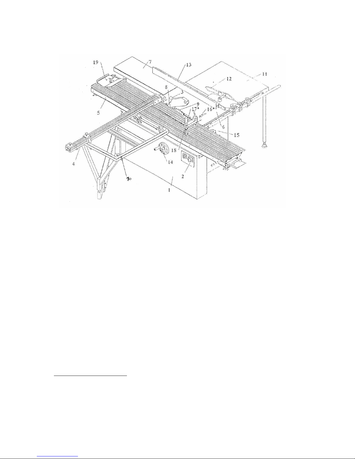
Building parts of the machine (picture 1)
1) Main corps
2) Main switch
3) Saw blade protections with possibility for the dustextraction
4) Retearable degree fence
5) Roller table (format table)
6) Working surface
7) Working surface enlargment
8) Riving knife
9) Saw blade max. diameter 315 mm
10) Additional table
11) Working surface enlargment
12) Moving cane
13) Parallel fence
14) Handwheel for square adjustment of the saw blade
15) Handwheel for the height adjustment of the saw blade
16) Installation screws for the scoring unit
17) Scoring blade
18) Excentric clamp
19) Fence
20) Telescopic support
21) Square fence with measurement
22) Additional table for format table
1.1 Purpose of the machine
The machine is exclusifely meant to cut solid wood, fibre plates, panel plates or other woodlike materials.
ATTENTION: With this machine you can only work on wood or wood-like materials!
The machine may only be used with the prescribed protection devices.
Page 6

Holztech S3.0 S2.5 S1.6
WWW.HOLZTECH.COM
2. Technical dates
Machine type S1.6 S2.5 S3.0
Table dimension part 6 800 x 500 mm 800 x 500 mm 1100 x 600 mm
Roller table 1600 x 350 mm 2300 x 350 mm 3200 X 350 mm
Additional table for roller 900 x 610 mm 900 x 610 mm 1200x610 mm
table part 10
Max. reach roller table 1600 mm 2500 mm 3000 mm
Add. worksurface part 7 850 x 320 mm 850 x 320 mm 900 x 400 mm
Addit. Worksurface part11 800 x 630 mm 800 x 630 mm 90 x 900 mm
Height workings surface 850 mm 850 mm 850 mm
Cutting width with parallel
Fence and surface enlarg.t 800 mm 800 mm 1250 mm
Length carpenter’s jqurare 1600 mm 1600 mm 2000 mm
Max. length degree fence 2800 mm 2800 mm 3320 mm
Max. diameter sawblade 315 mm 315 mm 315 mm
Min. diameter sawblade 250 mm 250 mm 250 mm
Shaftdiameter sawblade 30 mm 30 mm 30 mm
Max. cutting height 90°/45°
With sawblade 315 mm 103/72 mm 103/72 mm 103/72 mm
With sawblade 250 mm 70/49 mm 70/49 mm 70/49 mm
Sawblade stop within 10 sec 10 sec 10 sec
Speed main sawblade 4000 rpm 4000 rpm 4000 rpm
Diameter dustextr.connect. 120 mm 120 mm 120 mm
Motor 5,5 Hp 5,5 Hp 5,5 Hp
Noise level
Trial run 90 dB 90 dB 90 dB
Working 90 dB 90 dB 90 dB
Scoring unit (option)
Speed scoring blade 8000 rpm 8000 rpm 8000 rpm
Diameter scoring blade 120-125 mm 120-125 mm 120-125 mm
Shafthole scoring blade 20 mm 20 mm 20 mm
Weight 420 kg 450 kg 480 kg
Page 7
Holztech S3.0 S2.5 S1.6
WWW.HOLZTECH.COM
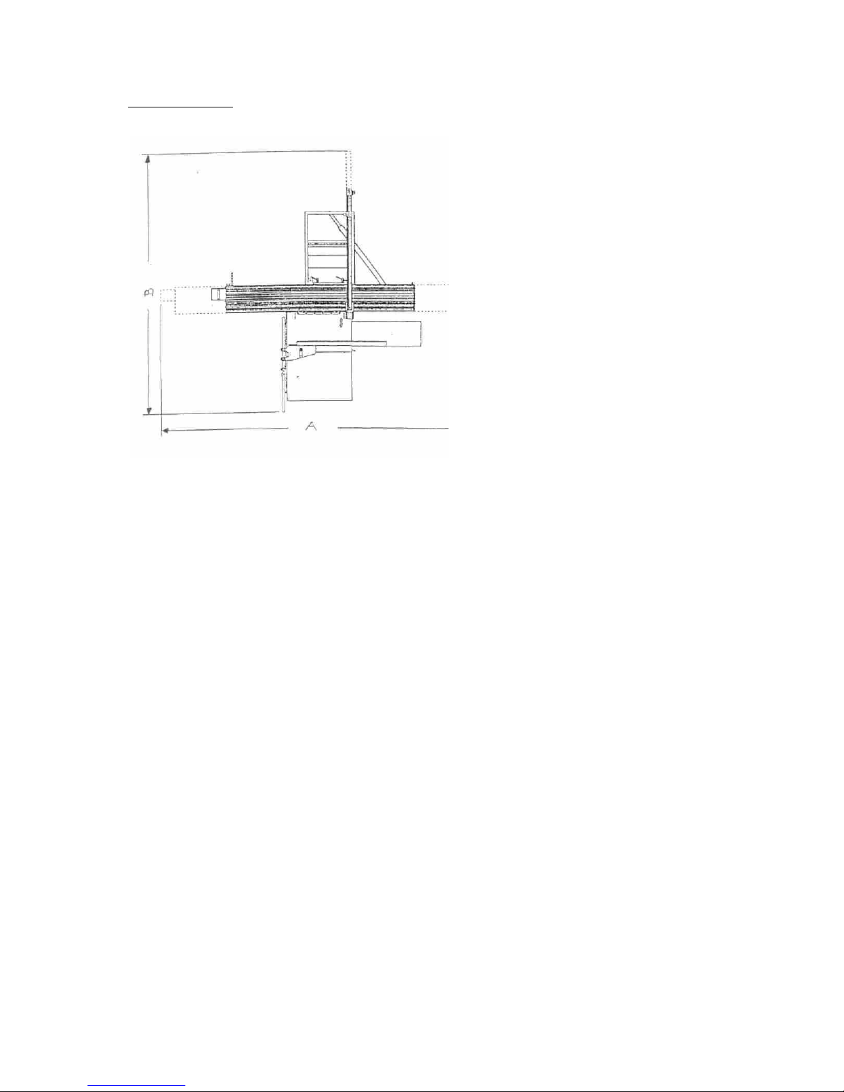
2.1 Building plan
S1.6 S2.5 S3.0
A 4000 mm 5500 mm 7500 mm
B 4100 mm 4100 mm 5200 mm
ATTENTION: When building up the
machine, pay attention that
there is enough space for a
safe working.
Page 8

Holztech S3.0 S2.5 S1.6
WWW.HOLZTECH.COM
3. Security prescriptions
3.1 Security directions
Don’t work without the prescribed security devices.
Please follow the instruction manual carefully.
Tear out the electricity plug at all maintenance, equiping and cleaning operations and
disturbances.
Test the security devices before working with the machine.
Never work with handgloves.
Keep the workplace and the machine always clean.
Pay attention to a good enlightning, without dark spots, in the workplace.
Don’t ever let the machine run unsupervised.
Before working, remove all unneeded pieces from the machine.
Before working, pay attention that the electrical connection is done skillfully.
Use the machine only for what it’s meant.
Pay attention to the max. speed of the used sawblade.
Only use a sawblade, when it’s well sharpened and without defects.
Stump sawblades overcharge the machine, give a bad working result and enheighten the
back-slash danger.
Let sharpen the tools only by skilled personnel.
Never use carved, deformed, for instance repaired sawblades, please throw these away
immediatly.
Page 9
Holztech S3.0 S2.5 S1.6
WWW.HOLZTECH.COM
Don’t work in humid rooms and don’t expose the machine to rain or low temperatures.
Don’t work with loose clothing, loose hair, sjawls, etc..
Take off your rings, chains, wristwatches and other, before working.
Always work with the prescribed protection devices (for instance hearing protection, ...)
Keep children away from the machine and make sure that children and unauthorised persons
can’t start the machine.
Youngsters under 16, may only use the machine under supervision of a skilled adult.
Pay attention that the machine is only served by persons who are familiar with the working
and the possible dangers, and who have full physical and mental capacities.
If it’s necessary to have auditif communication with other working or communication devices,
this devices must be completed with optical signs.
At a repairing, for instance
the installation of a saw
blade in connected
execution (outblowing
newer cutting plates) the
construction must stay the
same (form ot the teeth,
teeth width).
Connected tools
(Saw blade with solded
cuttin
g p
lates
)
Page 10

Holztech S3.0 S2.5 S1.6
WWW.HOLZTECH.COM
4. Security devices
The security devices of this machine is according to the safety prescriptions of all ECcountries.
The machine is equipped with the following safety devices:
a) Electronic motor brake
Thiss stops the shaft, when pushing the OUT- or EMERGENCY-button, within 10
seconds.
b) Endswitch
Is activated when the roller table is in the end-position, needed to change the sawblade,
or when flipping over of the sidewise sawblade protections, and avoids the starting of the
machine when replacing a sawblade.
c) Clamp
To clamp smaller workpieces.
d) Riving knife
Possible to install for the main blade of 250 to 315 mm diameter.
e) Sawblade covering with possibility for dustextraction
f) Possibility for dustextraction form down below
g) Several little aids (for instance a pushing cane).
h) Outlining fence
Page 11
Holztech S3.0 S2.5 S1.6
WWW.HOLZTECH.COM
5. Delivery prescription
Instruction manual
List sparts parts
4 feet for under the machine
Serving tools for equiping operations
1 excentric clamp
1 pushing cane
1 riving knife
1 sawblade covering with possiblilty for dustextraction
1 parallel fence with fine installation
1 degree fence, retearable
2 additional layers for working table enlargment
1 additional table for the roller table
1 outlining fence
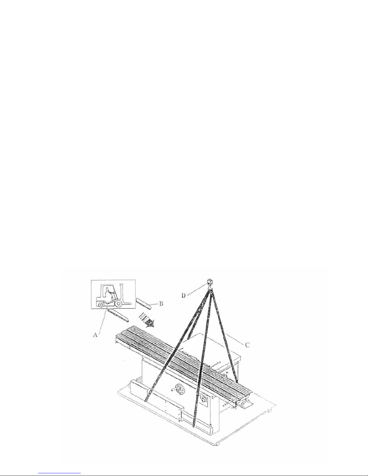
6. Transport prescriptions
Only transport the machine, when it’s screwed to the pallet.
To lift the pallet or to move the machine with belts or girdles, you must lift the machine only at
the therefor foreseen places.
When moving with a forklift, always use long forks and lift the pallet from the length direction.
ATTENTION: Lift and lower the machine without shocks!
Be sure that the machine is levelled!
Page 12
Holztech S3.0 S2.5 S1.6
WWW.HOLZTECH.COM
7. Preparing the machine for first use
7.1 Cleaning
All shining parts, which were protected against rust for transport, must be cleaned with petrol
or another degreasing products.
ATTENTION: Don’t ever use nitrothinning products or other solving products!
Don’t ever use water!
7.2 Building up
The machine must be levelled with all 4 installation feet, on a flat surface with a sufficient
bearing power.
The levelling operation of the machine can be done by turning the installation screws on the
feet of the machine.
Pay attention to have enough space around the machine.
This makes working more easy and lowers the danger level.
7.3 Preparation before working
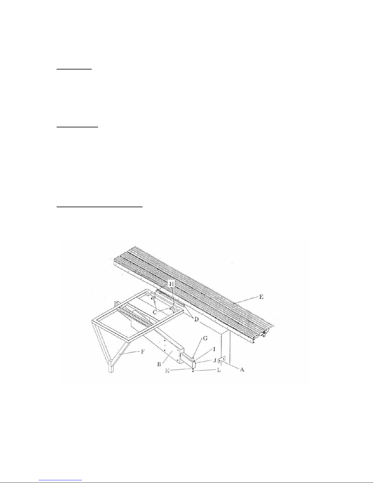
7.3.1 Mounting the additional table F (picture 5)
a) Loosen the transport security A from the telescopic support B.
b) Move the groove core D in the T-groove at the roller table.
c) Short screw the screw C with the add-ins to the thread D.
d) Place the additional table F on the bolts G and the screws C.
e) Test, if the onlay surfaces of both tables are parallel to each other and or on equal
heights.
When needes, you can change the installation with installation screws H und L.
Page 13
Holztech S3.0 S2.5 S1.6
WWW.HOLZTECH.COM
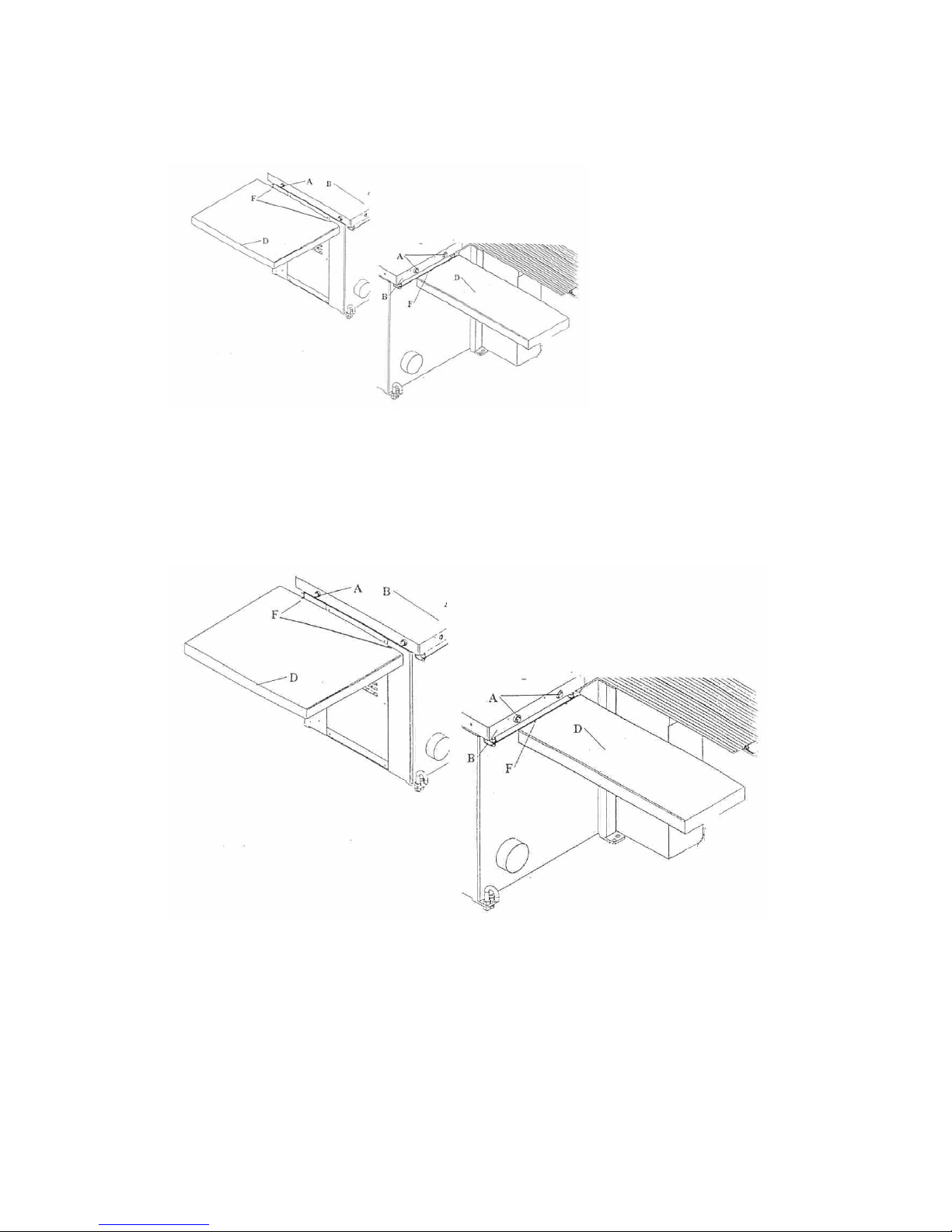
7.3.2 Mounting the working surface enlargments D (picture 6)
a) Loosen attachment screws A.
b) Screw supports C to layer D.
c) Place layer D on the attachment screws A.
d) Check if the table enlargments are flat and parallel with the table.
If needed, you can change this with the installation screws G and F.
7.3.3 Mounting the retearable degree fence C (picture 8)
a) Place the take-up-cane of fence C in one of the two drillings E on the additional table H.
b) Screw the fence with both screws A and B.
c) Test if the installation of the fence is 90° to the sawblade, if needed you can adjust this
with the installation screws.
Page 14
Holztech S3.0 S2.5 S1.6
WWW.HOLZTECH.COM
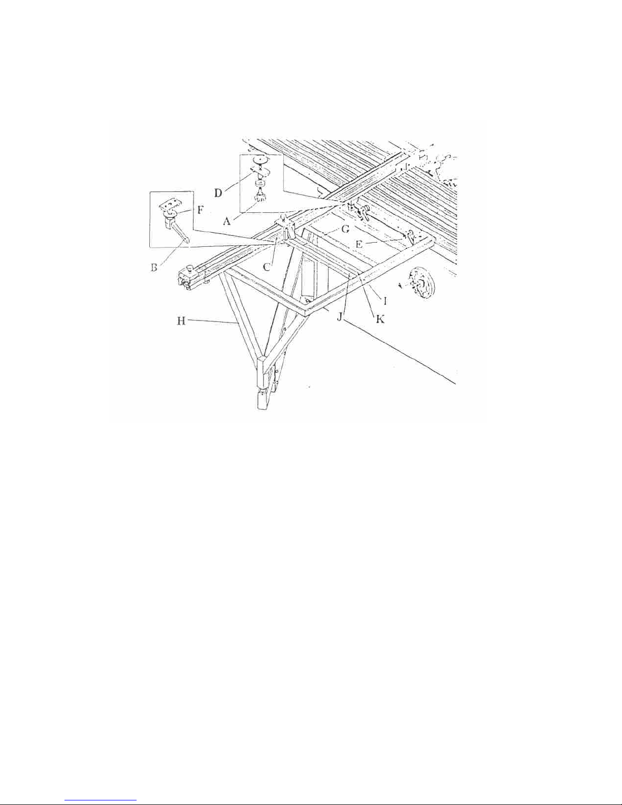
7.3.4 Mounting the parallel fence (picture 9)
a) Mount the degree L with measurement to the side of the working surface G and H.
The measurement start must flee with the teeth widht of the sawblade.
The installation is done by moving of the degree parts.
b) Fasten the bar F on the side of the working surface with the cane screw and bolt D.
c) Move bar J on bar f.
d) Fasten fence I on bar J.
e) Install the fence lineals parallel to the sawblade by adjusting the propulsion bars with the
attachment bolt.
Page 15
Holztech S3.0 S2.5 S1.6
WWW.HOLZTECH.COM
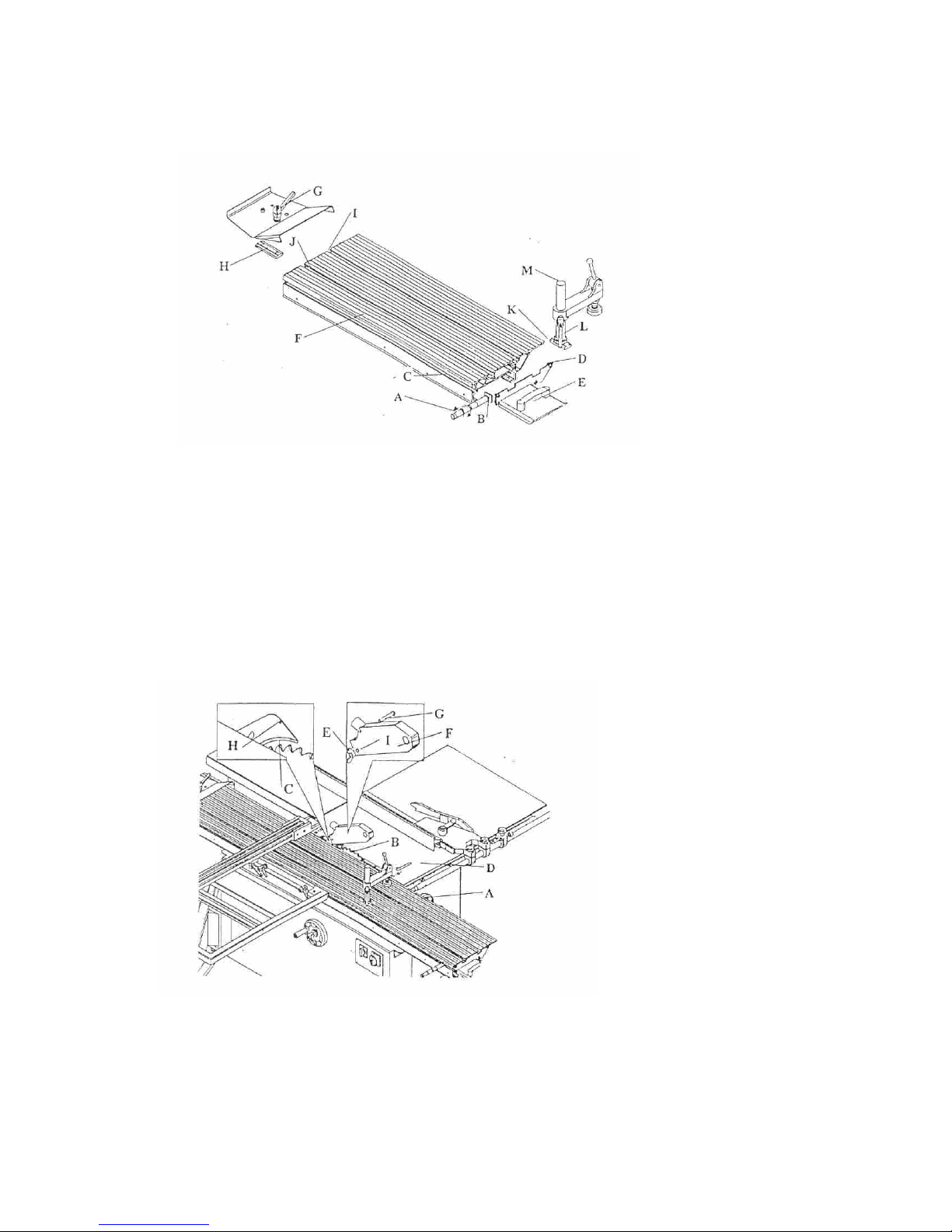
7.3.5 Completing the roller table (picture 10)
a) Mount the grip and move groove core B in the T-groove C of table F and srew groove
piece A in the thread of the groove core B.
The position of the grip on the working table can be chosen freely.
b) Screw covering E to the front side.
c) Mount the fence:
Move groove core H in T-groove J or I, put the fence on it.
Fasten screws G.
d) Mount the excentric clamp:
Move groove core K in T-groove J or I, screw column M and excenter arm with screw L.
7.3.6 Mounting the sawblade covering (picture 11)
Lift the saw-unit with handwheel A.
Place the sawblade covering on RIVING KNIFE C.
Fasten winged nut E in drilling H.
ATTENTION: Sawblade B must be lowered under working surface D to unmount
sawblade covering I.
Page 16

Holztech S3.0 S2.5 S1.6
WWW.HOLZTECH.COM
7.4 Electrical connection
The electrical connection may only be done by an electro-specialist.
The turning direction of the sawblade can be tested with short activiations.
When the turning directions isn’t right, let an electro-specialist correct it.
The 0 and protection-supply must be available.
ATTENTION: The switching off of the machine may only be done with the foreseen
switch, and certainly not by tearing out the electricity plug.
Page 17
Holztech S3.0 S2.5 S1.6
WWW.HOLZTECH.COM
8. Serving the machine
ATTENTION: Check before you start to work, if the machine runs normally!
When you notice vibrations, check the sawblade on defects and
swinging, on hard-metal sawblades you must look for defect teeth.
If there’s a defect, you must take out the sawblade.
The covering must be mounted so that the sawblade is fully covered.
When the sawblade is lowered under the working surface, you must
unmount the sawblade covering (part 3).
8.1 Adjusting the sawblade
Height adjustment:
Loosen screw H, put the sawblade in the desired height by turning handwheel D, fix screw H.
Adjusting the degree:
Loosen screw J, achieve the desired grade with handwheel I, fasten with screw J.
The adjustment can be read on the scale in the reach of handwheel G on the right side of the
machine.
When the sawblade is lowered under the working surface, you must remove the sawblade
protection.
8.2 Roller table
The roller table is stopped in the middle position by nut C.
Loosening the clamping screw B and fastening the bolts again, sets the table free.
8.3 Working positions
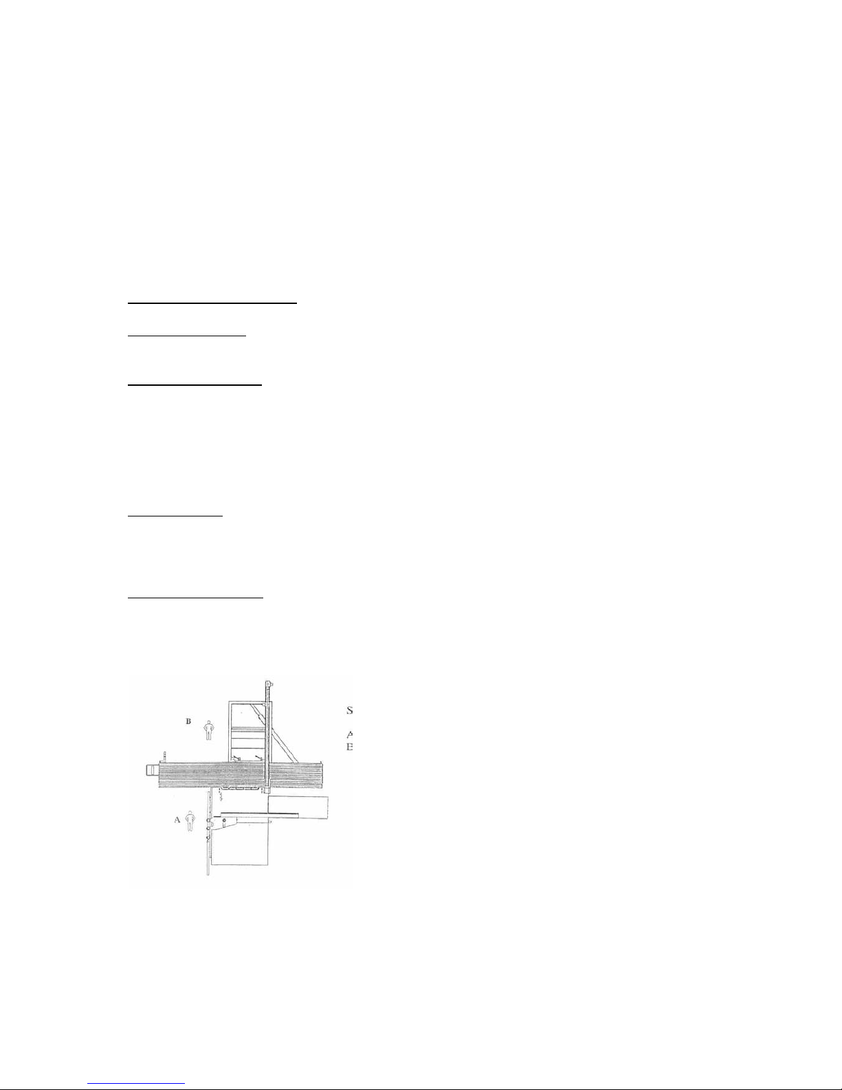
Serving the machine is only for one person.
Working position of the
workman
A. Working with the
parallel fence
B. Working with the roller
table
Page 18
Holztech S3.0 S2.5 S1.6
WWW.HOLZTECH.COM
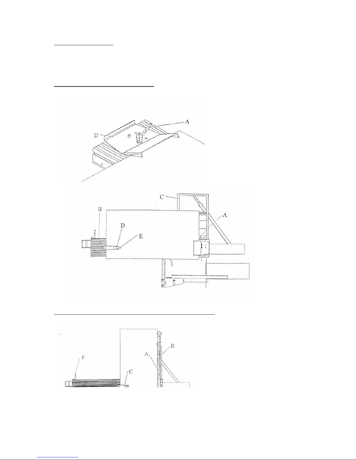
8.4 Working directions
You must use the roller table to cut longuer pieces!
Cutting with fence (picture 34 and 35)
Fig.
Cutting with retearable degree without sidefence (picture 36)
Mount fence D on table B,
push the plate or piece
against the fence and fix
with excentric clamp D,
like this, both ends are
pushed below.
Lay the workpiece against
the fence ons the desired
measurement and fix with
the excentric clamp.
Page 19
Holztech S3.0 S2.5 S1.6
WWW.HOLZTECH.COM
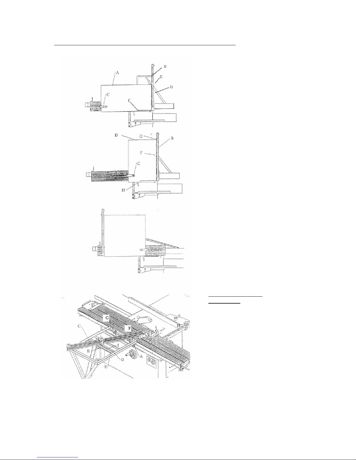
Cutting with the retearable degree and sidefence (picture 37 and 38)
Install fence E on the
desired cutting length, lay
workpiece A against the
installed fence and fix with
excentric clamp D.
Dependable ot the size of
the workpiece, you can
tear out the telescopic
part of the fence and so
prolong it.
When necessary, you
also place the fence for
other works from the front
side G to the back side F
(picture 39). The
workpiece is then moved
from the fence (mostly to
cut lighter plates).
Installing the degree
(picture 40).
Installing the degree of
fence C is done by
loosening the clamp
screw B and installing the
desired position by turning
the fence C around point
F.
The degreescales can be
found on E and D.
Page 20
Holztech S3.0 S2.5 S1.6
WWW.HOLZTECH.COM
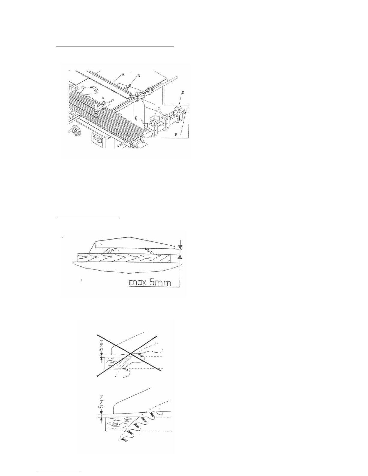
Working with the parallel fence (picture 30)
For thin workpieces, fence A can be turned 90° and converted. For that, the clamping of the
fence is loosened by turning handle B, the fence is taken off the bar and turned 90°, moved
back in the bar and fixed.
ATTENTION: When cutting smaller pieces, work with the moving cane or with the
other aids!
Installing the sawblade
Use this for workpieces
with two parallel moving
sides. The parallel fence
is fixed on the working
surface and can be
moved without gradations.
The installed
measurement can be
viewed on scale E.
Always look to the
sawblade that all the teeth
are covered with the
awblade covering. The
distance to the protection
hood can’t exceed 5 mm.
To improve the cutting
quality and to avoid that
the workpiece slashes
back, you must install the
sawblade so that at least
2 teeth cut the workpiece
simultanously.
When this isn’t possible,
you must use a sawblade
with finer teeth.
When cutting, move the
workpiece without chocs,
but move equally.
Page 21
Holztech S3.0 S2.5 S1.6
WWW.HOLZTECH.COM
Install the height and degree of the sawblade only when the machine is turned off.
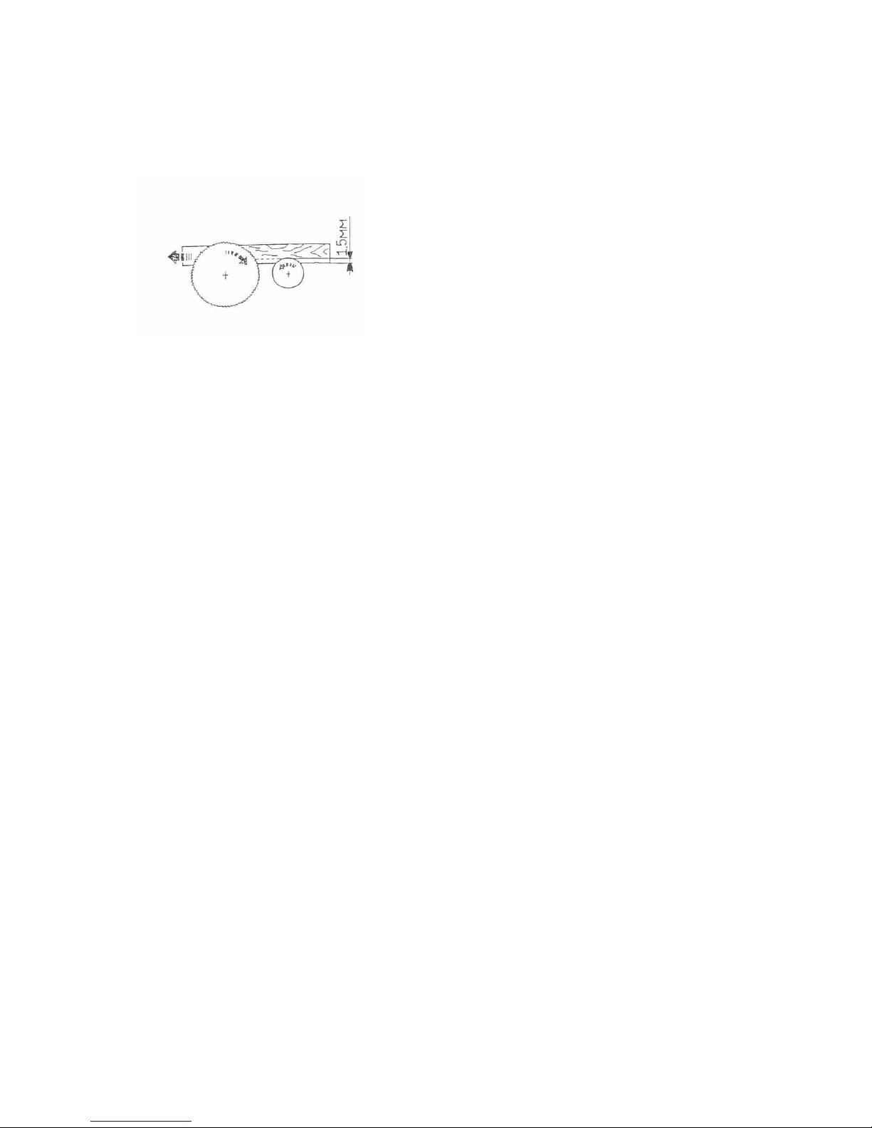
When cutting layered plates, you must use the scoring unit.
Harded sawblades must be cleaned
with an appropriate liquid, certainly not with a metal brush.
The cutting depth of the
scoring blade must be
approx. 1,5 mm.
Page 22
Holztech S3.0 S2.5 S1.6
WWW.HOLZTECH.COM
8.5 Taking out the sawblade
- Before you take out the sawblade, you must make sure the machine can’t be started.
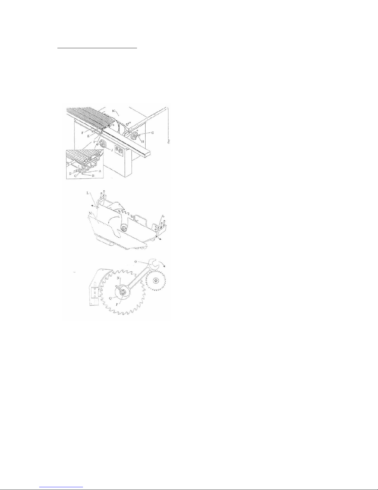
TAKE OUT THE ELECTRICITY PLUG!!!
Bring the saw-unit with
handwheel G to the
highest position. Move the
roller table as much as
possible to the front, over
the fence, so that the
fence pen D is teared out
(picture 14).
Deregulate protection
plate M (picture 15) by
pushing from the side on
surface spring L and flip it
over.
Unscrew the fixing nut P
to the right (picture 16)
with key Q (SW32) and
hold it with key N (SW10)
(Left rhreaded).
Take off the fixing flang
and take off the sawblade.
Page 23
Holztech S3.0 S2.5 S1.6
WWW.HOLZTECH.COM
8.6 Placing the sawblade
Move the new sawblade on the shaft.
ATTENTION: Pay attention to the direction of the teeth.
Move the clamping flange on the shaft, paying attention that the flange lays against the
sawblade, if necessary turn it untill it moves on it (turning security).
Turn on the fixing nut by turning it to the left (holding it with a thorn or an imbuskey).
Test the turning by hand, if the sawblade turns around freely.
Flip down the protection plate.
Retear the roller table from the most far position.
Shortly activate the machine to be sure that the sawblade turns without defects.
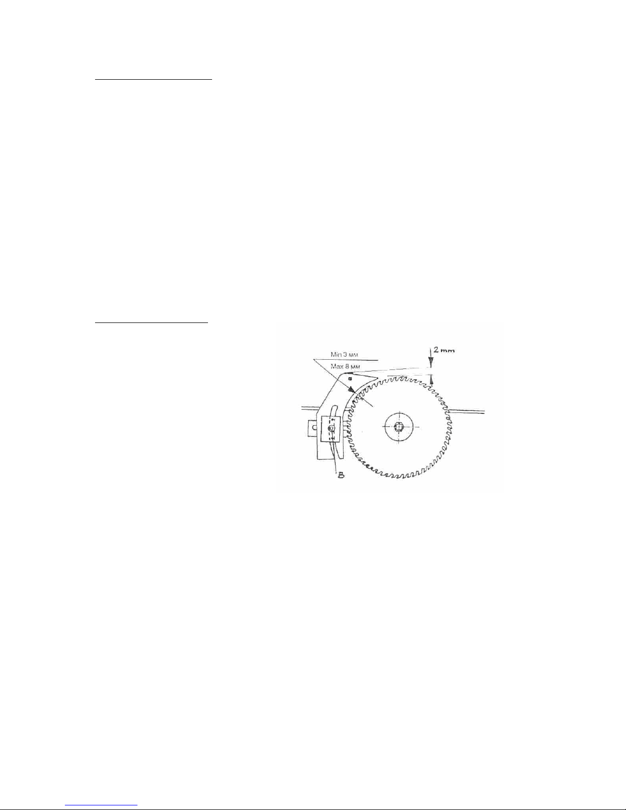
ATTENTION: When a sawblade with another diameter is installed, you must re-install
the riving knife!
Installing the riving knife
ATTENTION: The distance from the riving knife to the sawblade must be min. 3 mm
and max. 8 mm.
The upper side of the riving knife must be min. 2 mm above the height of the
teeth.
Loosen nut B , adust the
riving knife to the
sawblade.
Refasten nut B.
Page 24
Holztech S3.0 S2.5 S1.6
WWW.HOLZTECH.COM
8.7 Scoring unit
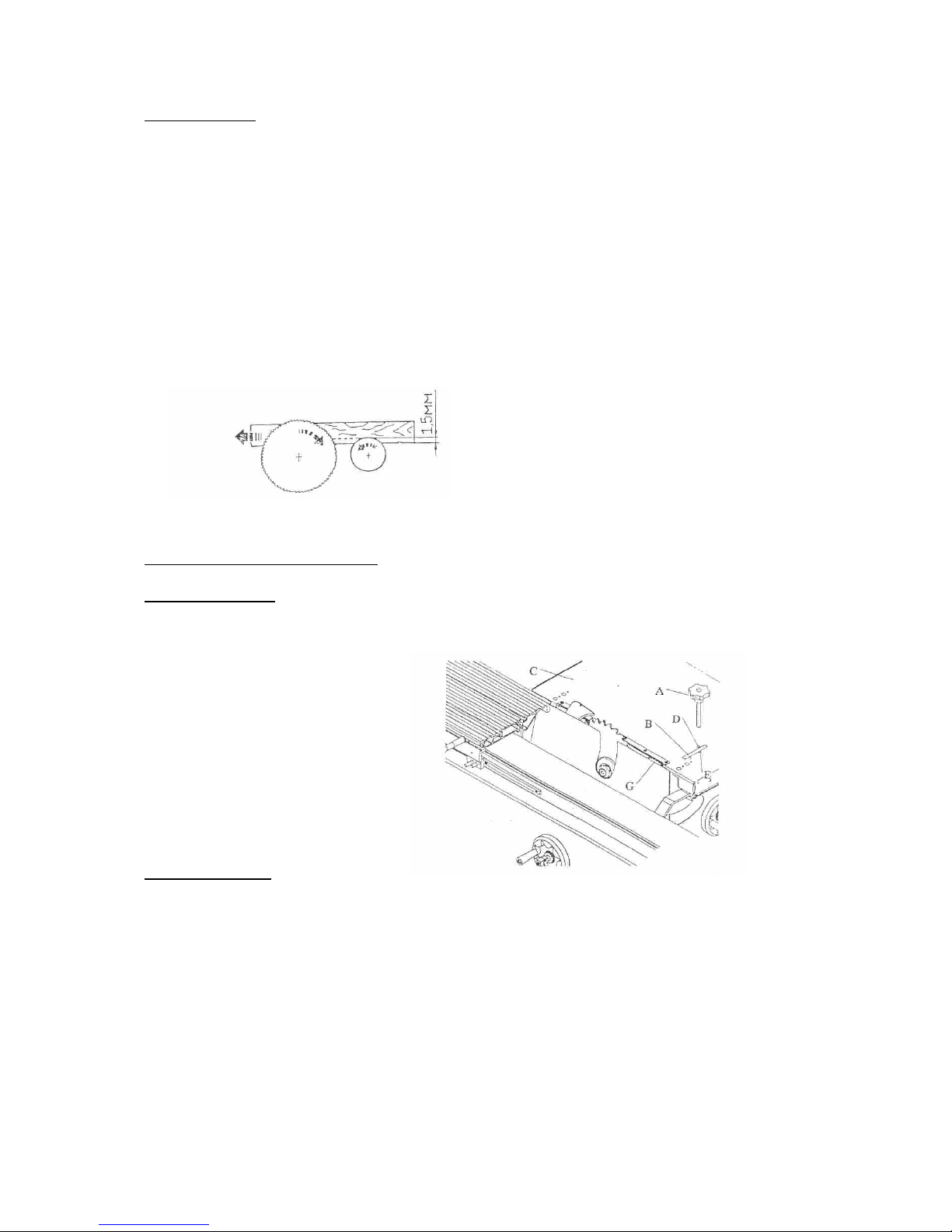
8.7.1 Installing and taking out of the scoring blade.
The installation or taking out of the scoring blade is done like by the main sawblade, you
must also take the same safety measurements (tear out the electricity plug).
Pay attention to the following differences:
The fixing nut of the scoring blade is right-threaded, so you must loosen it by turning to the
left.
The position of the teeth of the scoring blade is installed in opposite of the teeth of the main
blade, because the turning direction of both blades is in opposite to each other (picture 16).
8.7.2 Adjusting the scoring blade
Height-adjustment
Tilting-adjustment
Put key A in the drilling E on the square and by turning, you obtain the desired tilting.
This adjustment is a fine adjustment, which is almost more viewable, because the main
installations are already done when mounting the machine.
The scoring blade must be
installed so that the max. cutting
depth is 15 mm (picture 25).
Put key A in the drilling B
on the square and by
turning you adjust the
height.
Page 25

Holztech S3.0 S2.5 S1.6
WWW.HOLZTECH.COM
8.8 Safety directions
When installing a sawblade, you must pay attention that the shaft diameter of the blade is
equal to the shaft diameter of the machine.
Don’t ever mount a blade with a bigger shaft diameter.
Defect or deformed sawblades may not be repaired.
You must throw them away immediatly.
Stump sawblades may only be sharpened by skilled people.
At a repairment, for instance setting right a layered sawblade (welding new cutting plates),
the construction must stay the same (form of the teeth, for instance the width).
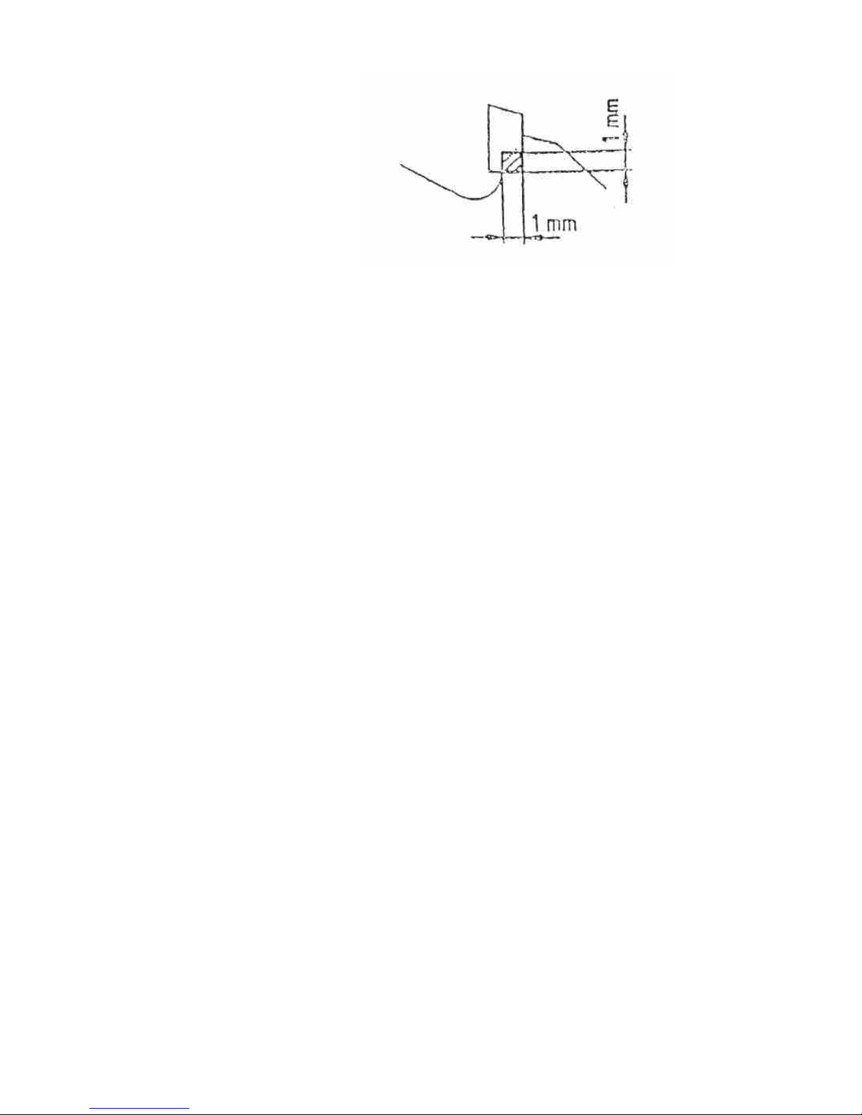
Layered tools (sawblades with welded cutting plates) may only be slitted to a max. diameter
of 1 mm.
Page 26
Holztech S3.0 S2.5 S1.6
WWW.HOLZTECH.COM
9. Maintenance of the machine
ATTENTION: Before starting maintenance works, you must be sure that the machine
can’t be started, so you must always tear out the electricity plug!!!
You must test the cutting plates of the sawblades (stump or broken
teeth, defects...) and when necessary replace the sawblade.
9.1 Cleaning the machine
The machine must be cleaned frequently and profoundly of all dust and splinters.
9.2 Greasing the machine
The roller bearings of the roller table and the parallel fence must be greased frequently
slightly with an oilspray.
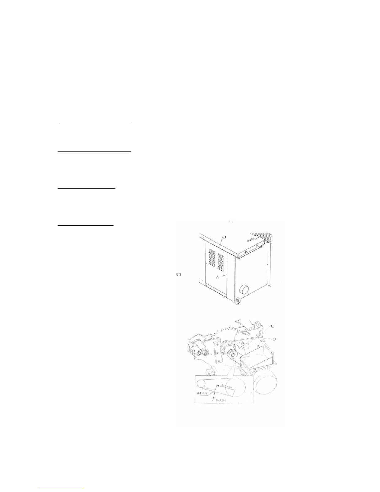
9.3 Testing the belts
You must test the belts after the first 10 hours of working and if necessary, tighten them, later
on you must check them frequently and tighten them if necessary.
Tightening the belts
ATTENTION: Don’t tighten the belts too much, otherwise you may damage the roller
bearings.
Unscrew the back
covering B (picture 41).
Test the tension of the
belts by pressing, when
the tension is too low,
loosen 6-sided-nut D and
fasten 6-sided-nut C untill
the belts are inbetween
the discs and it can be
pressed approx.. 4 or 5
mm (picture 42).
Page 27

Holztech S3.0 S2.5 S1.6
WWW.HOLZTECH.COM
9.4 Testing the motorbrakes
The machine is equiped with an electronic motorbrake.
The period from shutiing down the machine untill complete stop may not exceed 10 sec..
You must test the brakes monthly.
It the braking period is longuer than 10 sec., you must let test the motorbrake by a skilled
technician and replace it if necessary.
ATTENTION: Switchfrequence max. 10 times/hour.
Page 28
Holztech S3.0 S2.5 S1.6
WWW.HOLZTECH.COM
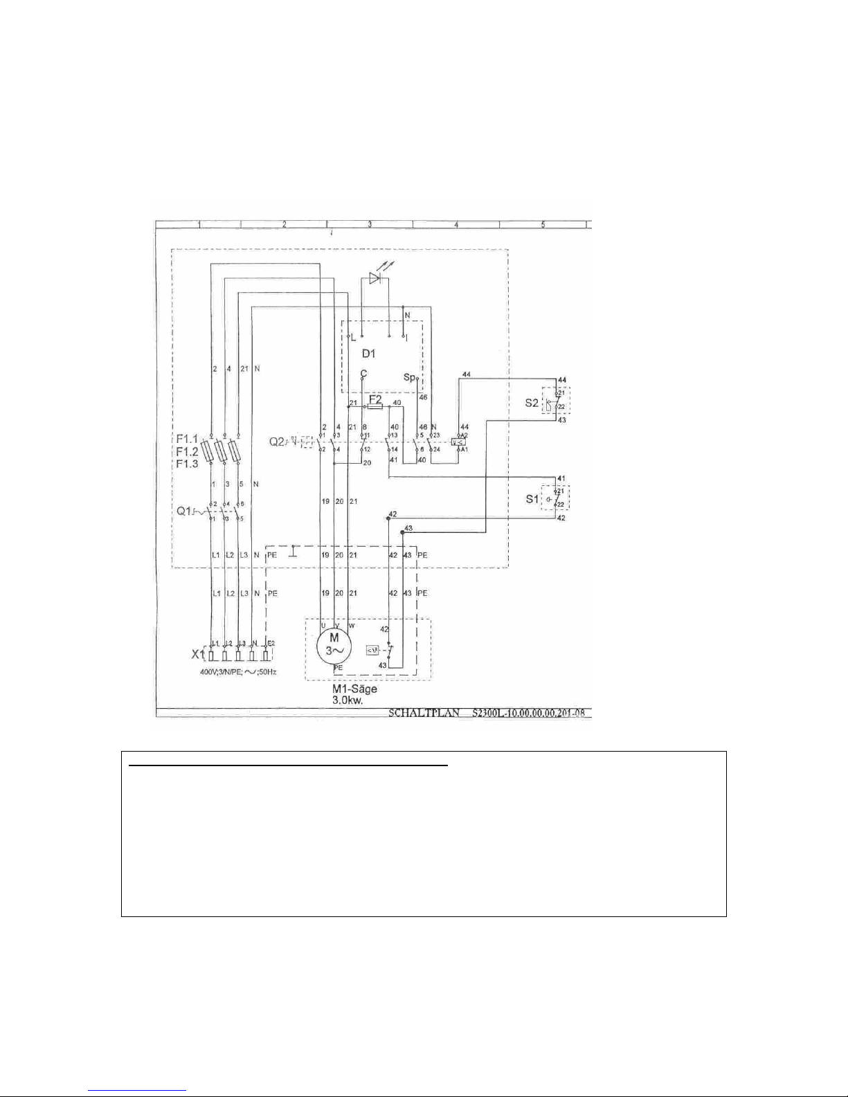
10. Electric drawing
Sign Name Art. Nr.
Q1 Switch M220-61199-033M1
Q2 Switch KB-S-30; Uc=220V; 50Hz
D1 Electro motorbrake TES 71 10/230
S1 Emergency-stop button XAL-J01 / ZA2-BT4
S2 Endswitch FX-515
F1.1 Security V/099-004116
F1.2 automat
F1.3
F2 Fuse UK4-TG / ST-SI-UK4 / PP-20.250V.0.2A
X1 CEE-plug 515-6;3P+PE
M1 Motor T90LB-2D;B3;3.0kW;400V;50Hz;11.1/6.4A;dY;2860/min.
Page 29
Holztech S3.0 S2.5 S1.6
WWW.HOLZTECH.COM
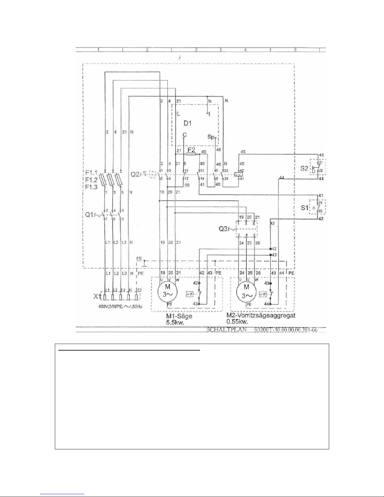
Sign Name Art.Nr.
Q1 Switch M220-61199-033M1
Q2 Switch KB-S-30. Uc=220V;50Hz
Q3 Switch T212-61003-003M1
D1 Electro motor brake No:4082.05;250V;16A
S1 Emergency-stop button XAL-J01 / ZA2-BT4 / ZA2-BZ102
S2 Endswitch FX-515
F1.1 Security V/099-004125
F1.2 automat
F1.3
F2 Fuse UK4-TG / ST-SI-UK4
PP-20;250V.0.2A
X1 CEE-plug 515-6;3P+N+PE
M1 Motor T112MB-2;B3;5.5kW;230/400V;50Hz;11.6A;dY;2860/min.
M2 Motor MO71B/2D;B14;F115;0.55kW;230/400V
50Hz;2.42/1.4A;dY;2760/min.
Page 30
Holztech S3.0 S2.5 S1.6
WWW.HOLZTECH.COM
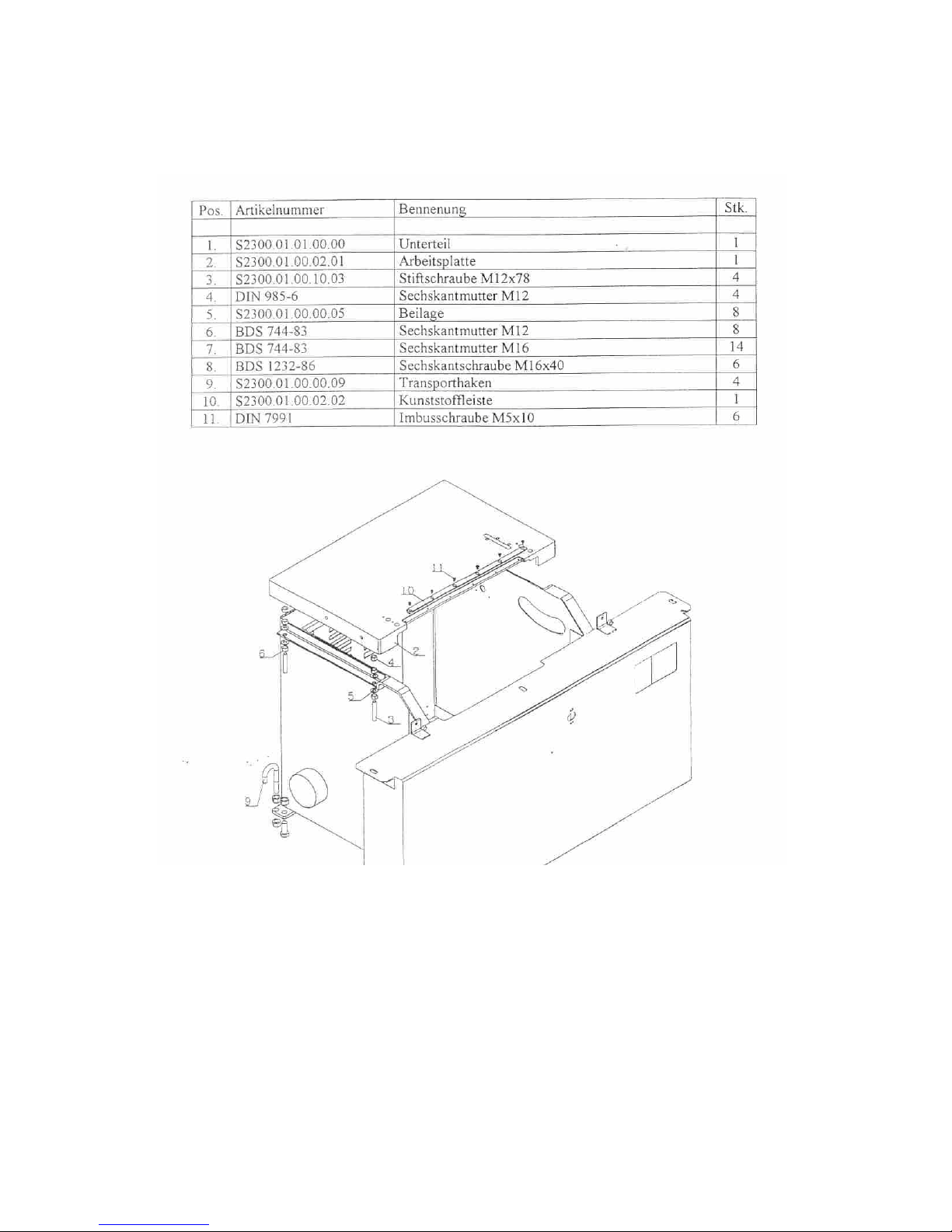
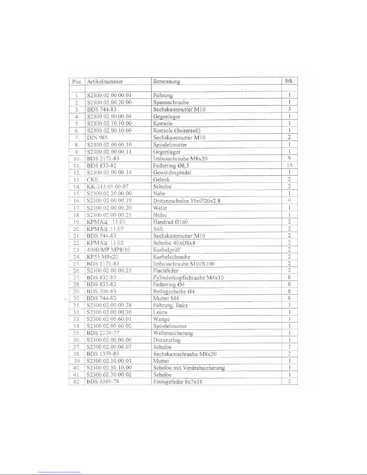
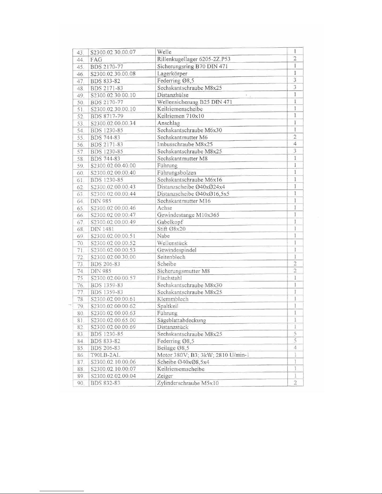
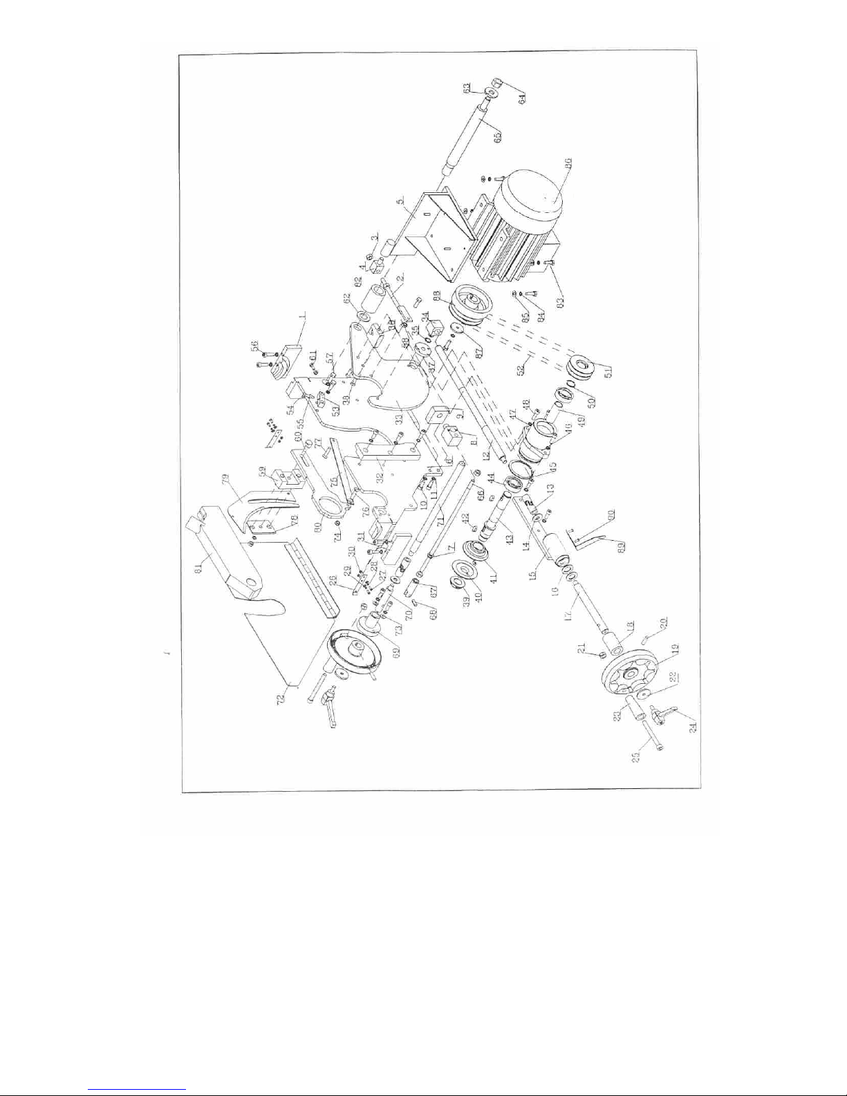
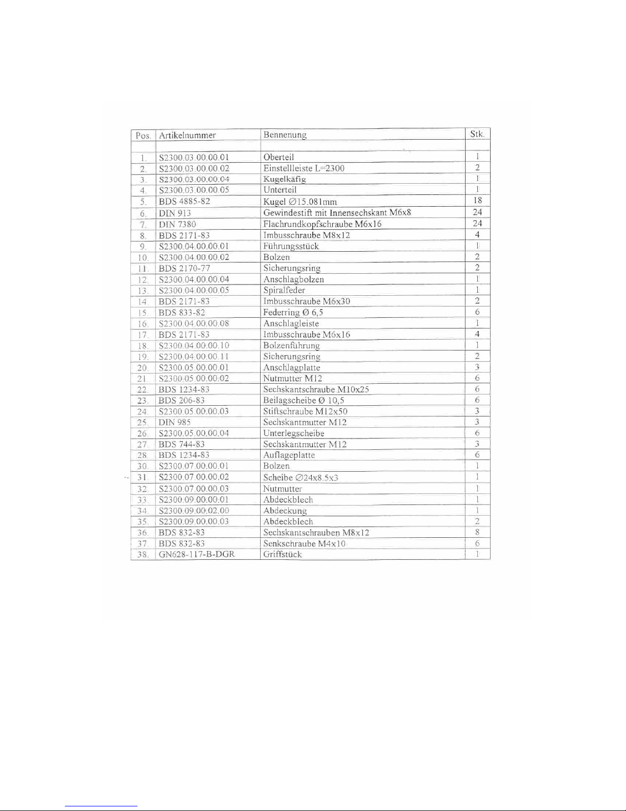
11. List of the spare parts
S2300.01.00.00.00 Machine main corps
Page 31
Holztech S3.0 S2.5 S1.6
WWW.HOLZTECH.COM
S2300.02.00.00.00 Sawunit
Page 32
Holztech S3.0 S2.5 S1.6
WWW.HOLZTECH.COM
Page 33
Holztech S3.0 S2.5 S1.6
WWW.HOLZTECH.COM
Page 34
Holztech S3.0 S2.5 S1.6
WWW.HOLZTECH.COM
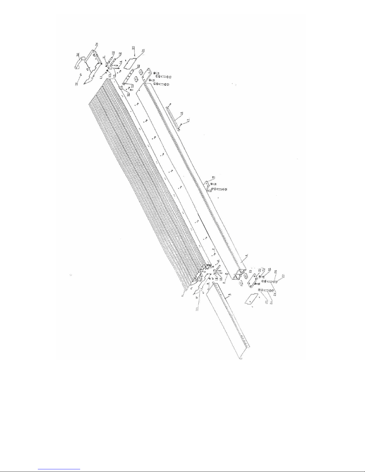
S2300.07.00.00.00 Roller table
Page 35
Holztech S3.0 S2.5 S1.6
WWW.HOLZTECH.COM
Page 36
Holztech S3.0 S2.5 S1.6
WWW.HOLZTECH.COM
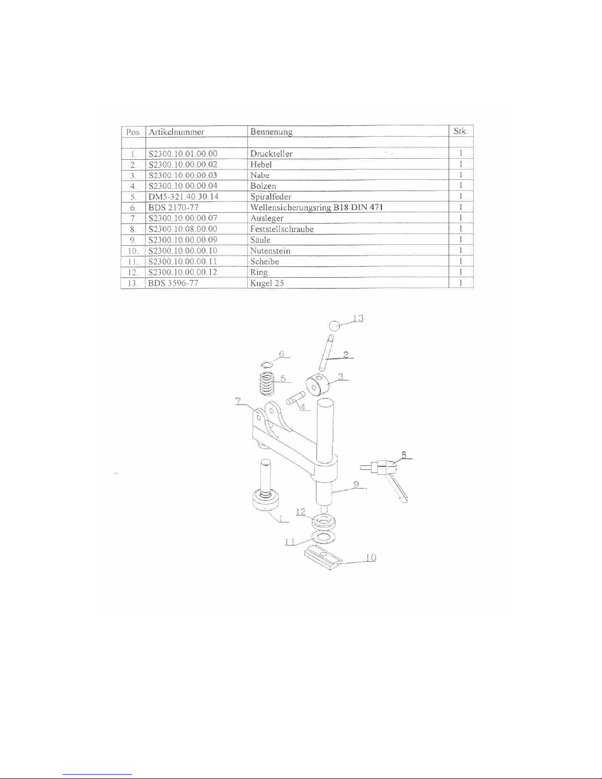
S2300.10.00.00.00 Excentric clamp
Page 37
Holztech S3.0 S2.5 S1.6
WWW.HOLZTECH.COM
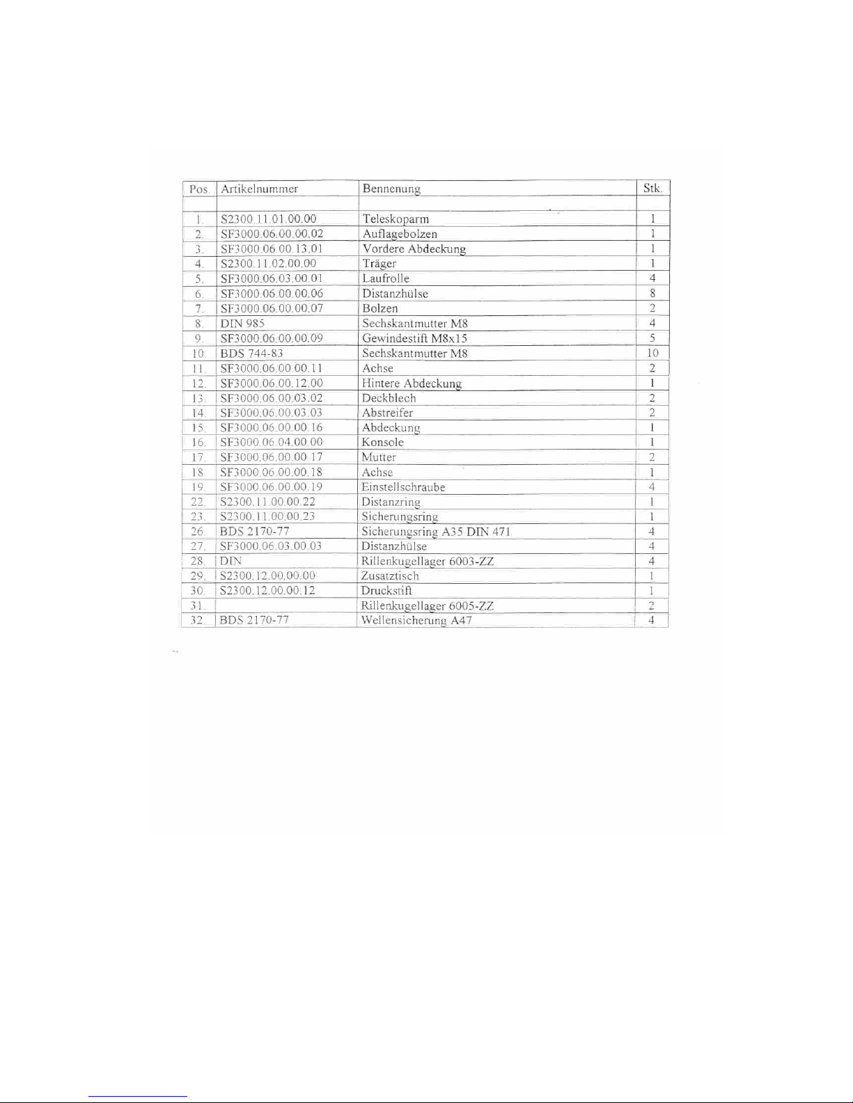
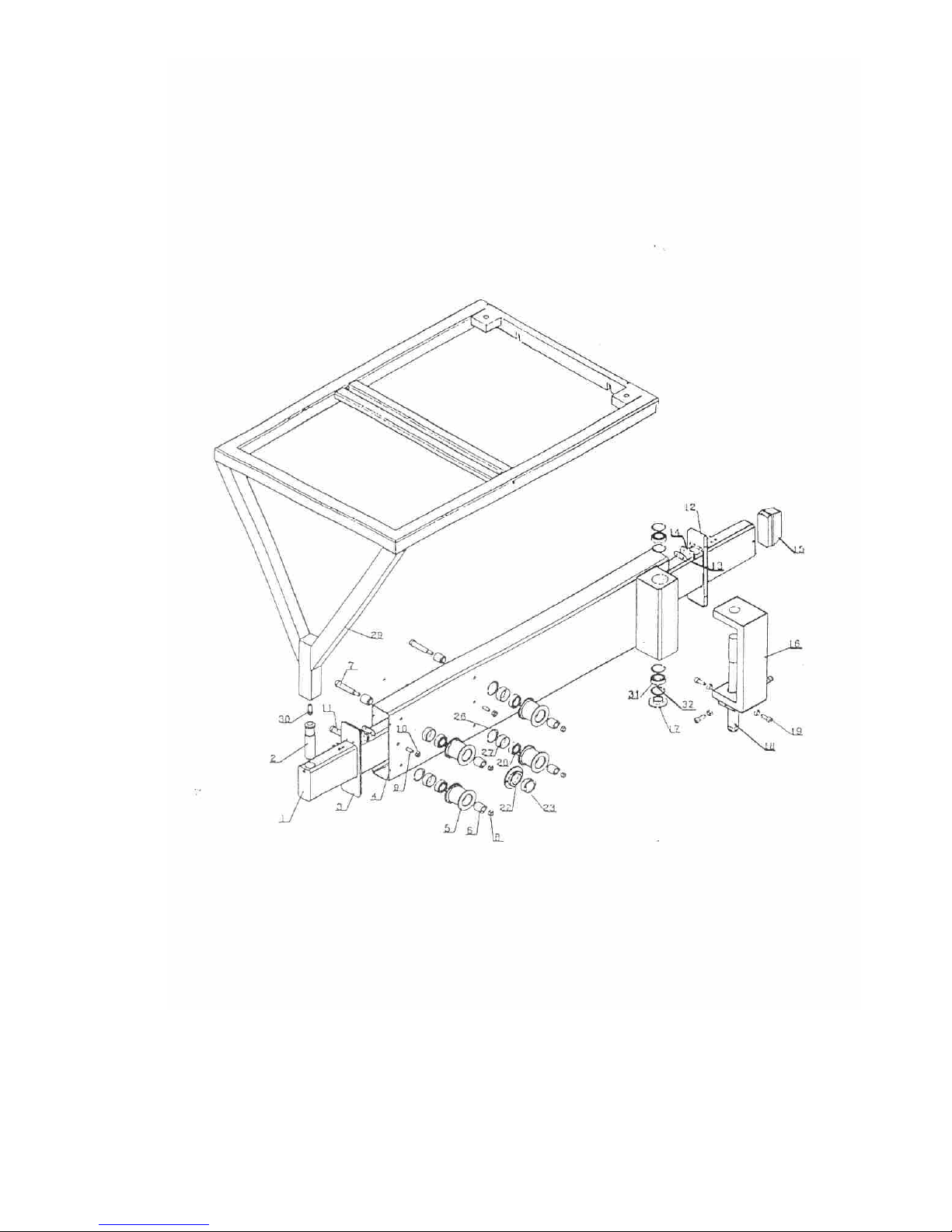
S2300.11.00.00.00 Telescopic support
Page 38
Holztech S3.0 S2.5 S1.6
WWW.HOLZTECH.COM
Page 39
Holztech S3.0 S2.5 S1.6
WWW.HOLZTECH.COM
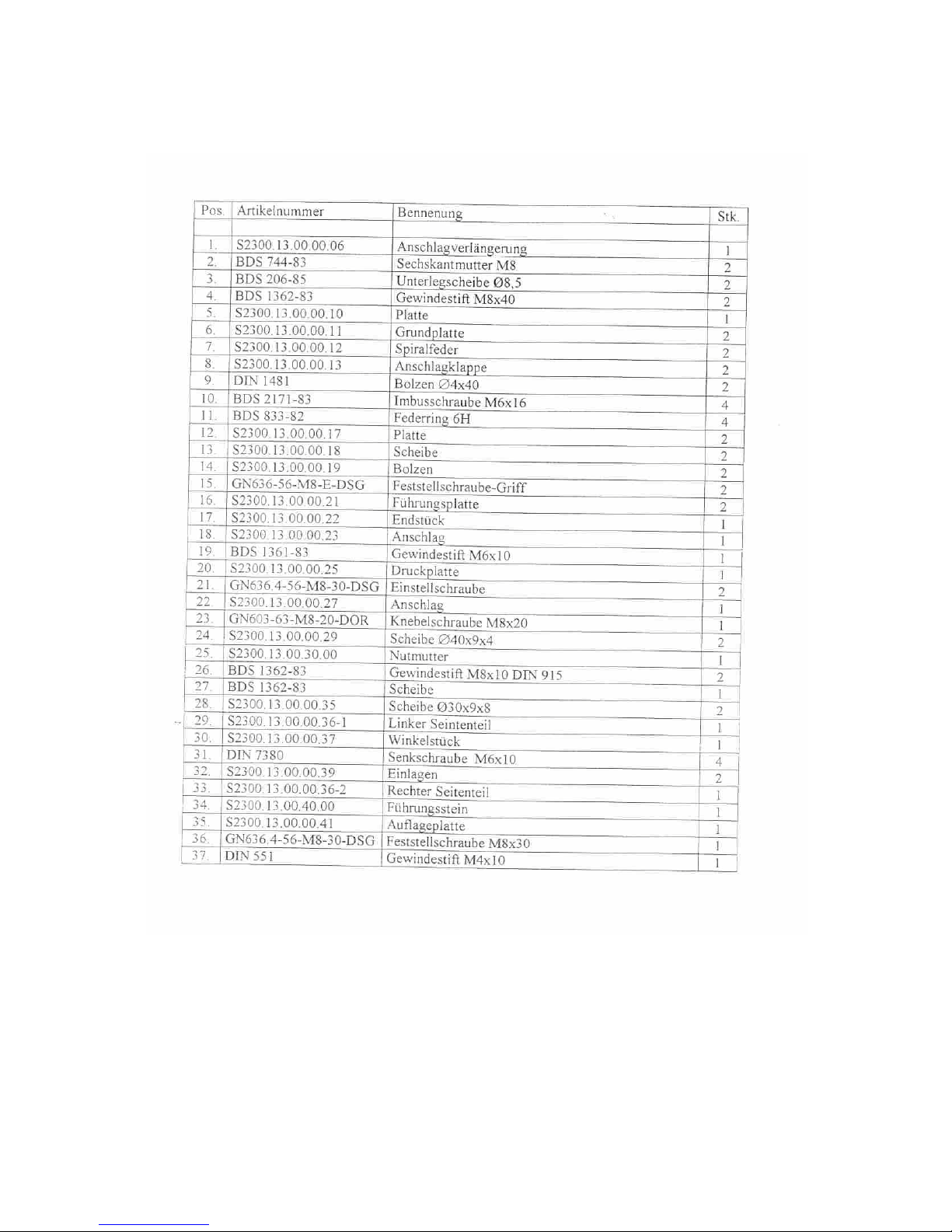
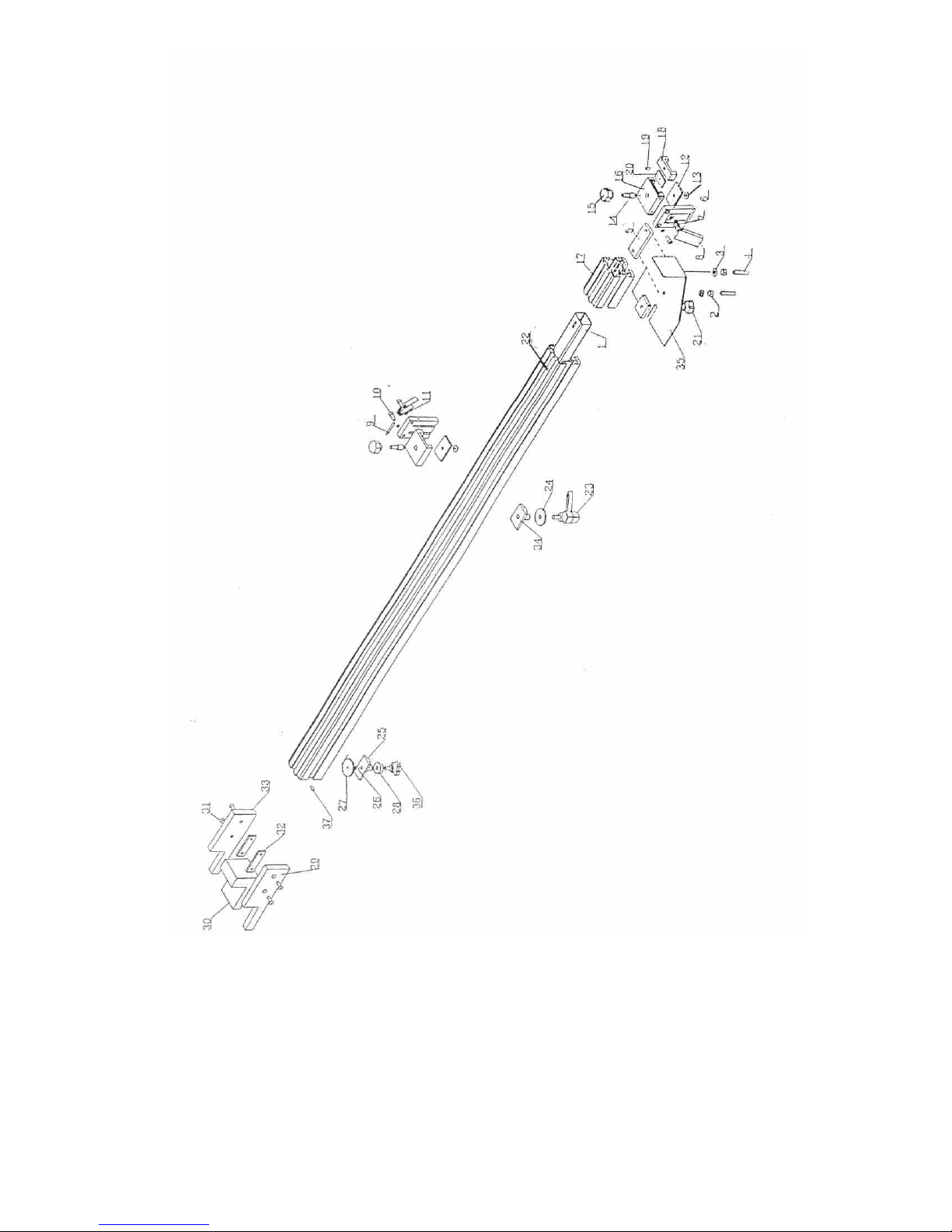
S2300.13.00.00.00 Telescopic fence
Page 40
Holztech S3.0 S2.5 S1.6
WWW.HOLZTECH.COM
Page 41
Holztech S3.0 S2.5 S1.6
WWW.HOLZTECH.COM
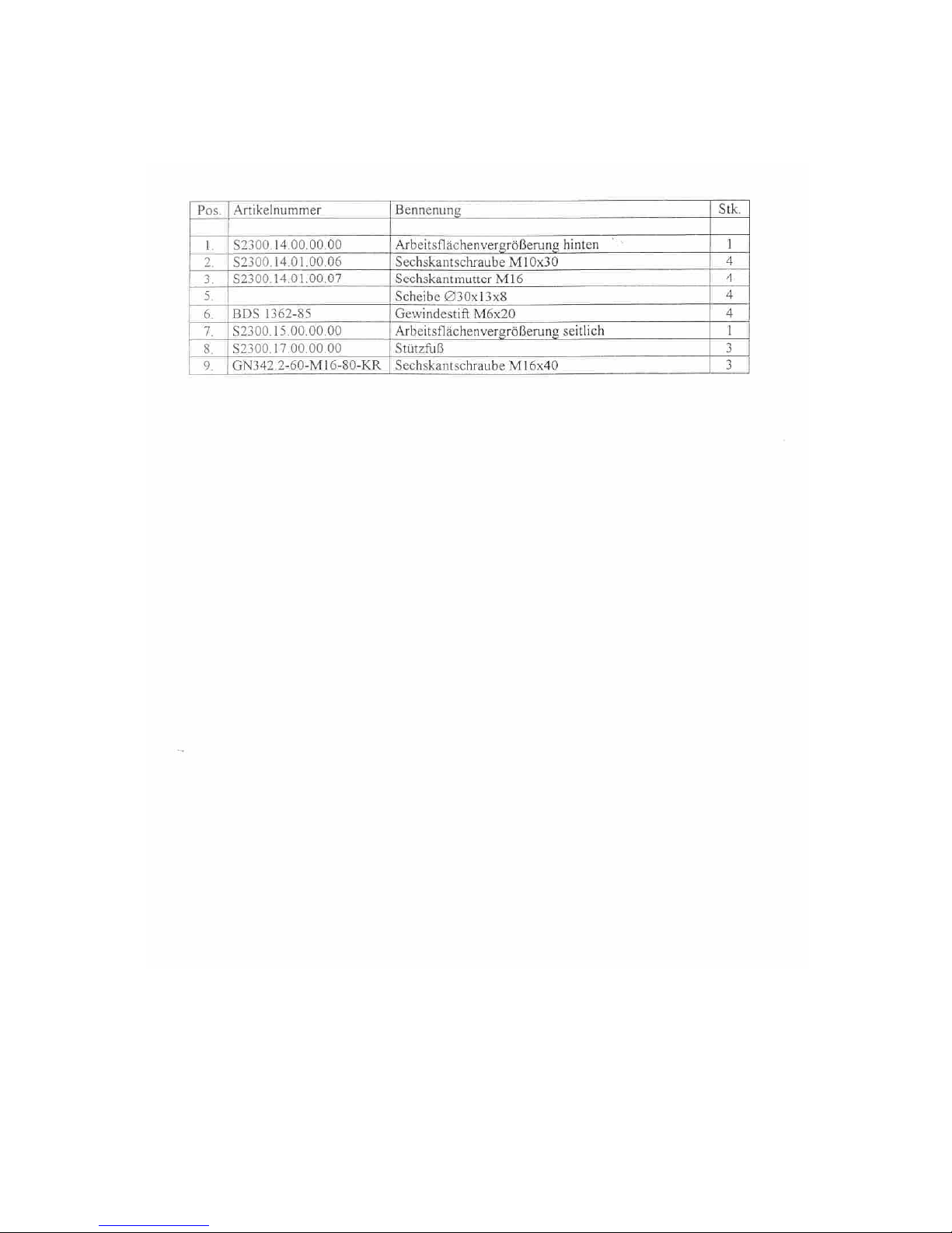
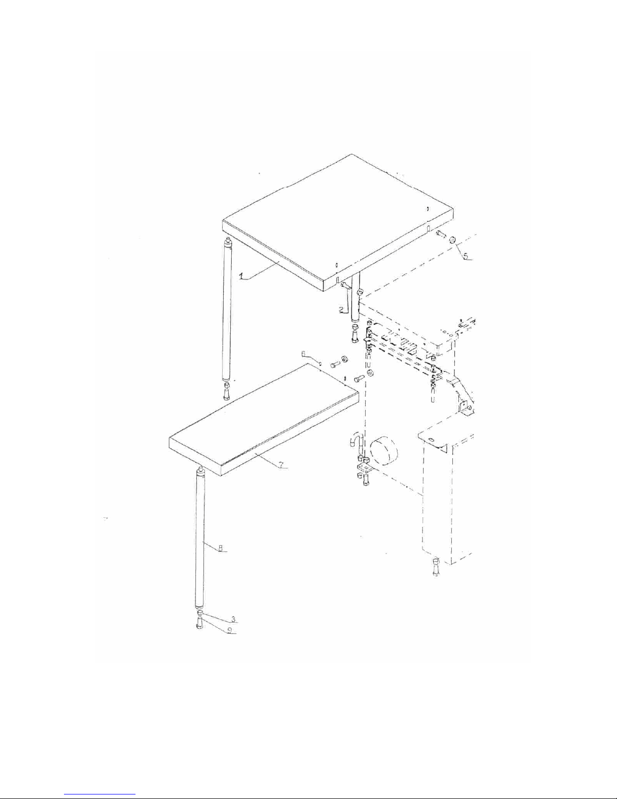
Working surface enlargment
Page 42
Holztech S3.0 S2.5 S1.6
WWW.HOLZTECH.COM
Page 43
Holztech S3.0 S2.5 S1.6
WWW.HOLZTECH.COM
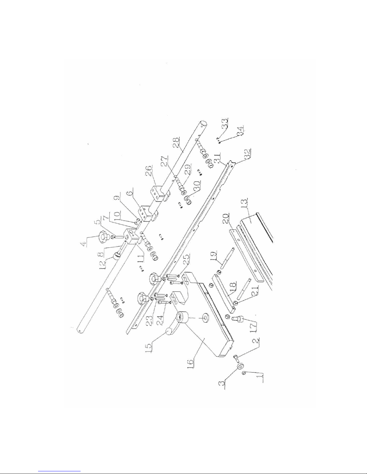
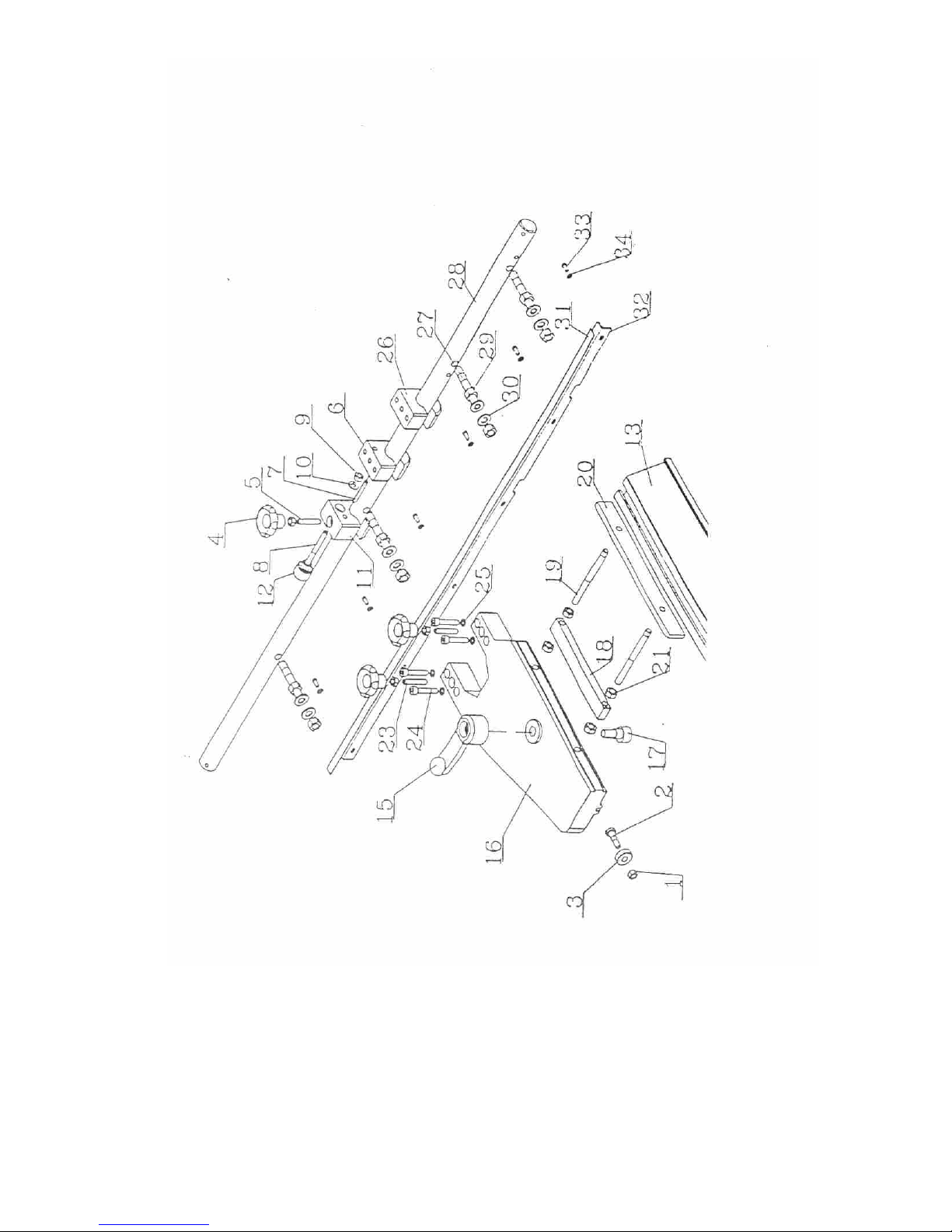
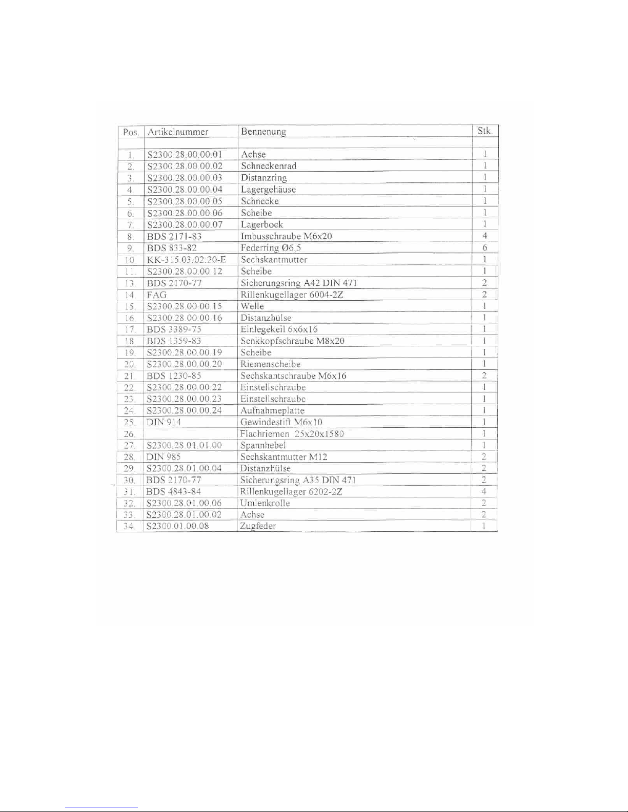
S2300.16.00.00.00 Parallel fence
Page 44
Holztech S3.0 S2.5 S1.6
WWW.HOLZTECH.COM
Page 45
Holztech S3.0 S2.5 S1.6
WWW.HOLZTECH.COM
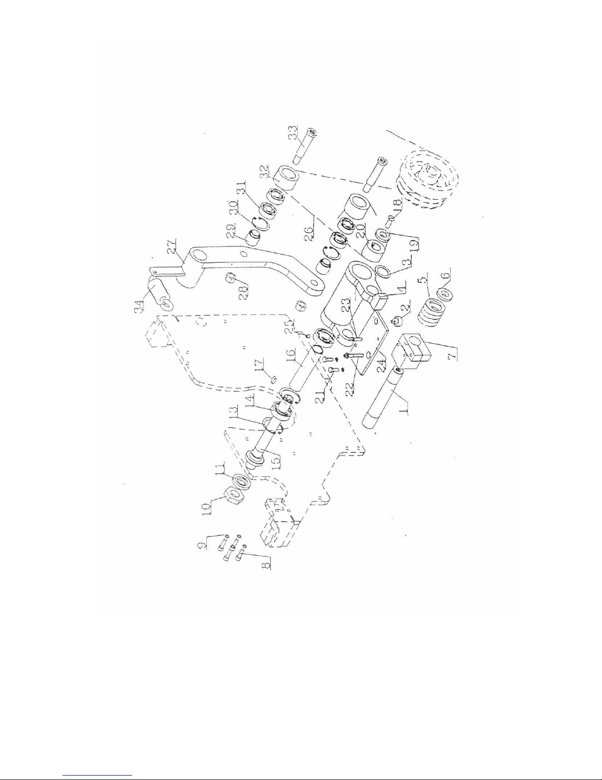
S2300.28.00.00.00 Scoring unit
Page 46
Holztech S3.0 S2.5 S1.6
WWW.HOLZTECH.COM
 Loading...