

Page 1

E- Purito Holzmodellbau Schweiger
construction manual
Some notes in advance:
Please read these assembly and safety instructions carefully before starting construction and
proceed step by step when building. Make sure you understand the individual building steps.
This kit is suitable for children from 14 years old. Construction and operation of the airplane
should be under the supervision of an adult.
The flight model is suitable for E-RES competitions, slope and thermal flying in calm weather.
Caution: high flight is not appropriated. At high altitudes and in windy conditions, it may not
be possible to estimate the correct flight speed.
The manufacturer gives no liability for damage resulting from improper use.
A non-intended use is, among other things, to assemble the kit differently as descripted at
the following construction manual or to use the flight model differently as described in the
assembly instructions. Please also have a look at our website for further information’s:
www.holzmodellbau-schweiger.de
When building the model, observe all safety regulations for handling tools and adhesives.
We use thick and thin superglue for assembling the model unless otherwise specified.
Particular care must be taken to ensure that the components are properly glued.
You can also find a very good build log at:
https://www.rcgroups.com/forums/showthread.php?3656529-PURITO%21-New-F3RESSailplane
- The operation of model aircraft of this type requires model aircraft liability insurance
- Please check with your local authority, if you need a pilot registration. In the EU
(beginning of 1st of January 2021) this is required.
- Do not operate the model in unfavorable weather conditions (thunderstorms, strong
winds, etc.)
- Do not operate the model in the vicinity of high-voltage lines or close to urban
structures.
- Do not operate the model, if it shows any signs of damages or failures in the remote
control equipment.
We will be happy to answer any questions you might have, please contact via email:
[email protected]
Errors and spelling mistakes reserved.
Page 2

2
Description electric fuse:
We start with the fuselage
slipway: the parts of the slipway
are on a separate 3mm poplar
plywood board. The stops are
carefully cut out and glued into
the slots provided. Stop 1 is
provided for slot 1, stop 2 for
slot 2, etc.
The slipway for the fuselage boom is on a 3mm balsa board and is glued as well.
Thee directions L (left) and R (right) are in the direction of flight. For components R7 to R10,
make sure that there is a left and a right part each, since the motor bulkhead is glued with
side pull. The side pull in the motor bulkhead shortens the right side of the fuselage and
lengthens the left side.
On the 2nd picture you can see all the parts that are needed for the construction. The parts
are arranged in the picture as they will be assembled. The 0.6mm plywood reinforcement
R10 is already glued to the balsa side R9 with white glue. The right half of the fuselage is the
shorter side, so parts R7 and R8 are also shorter. They are glued together with R6 to the
fuselage half as shown in the picture.
Page 3
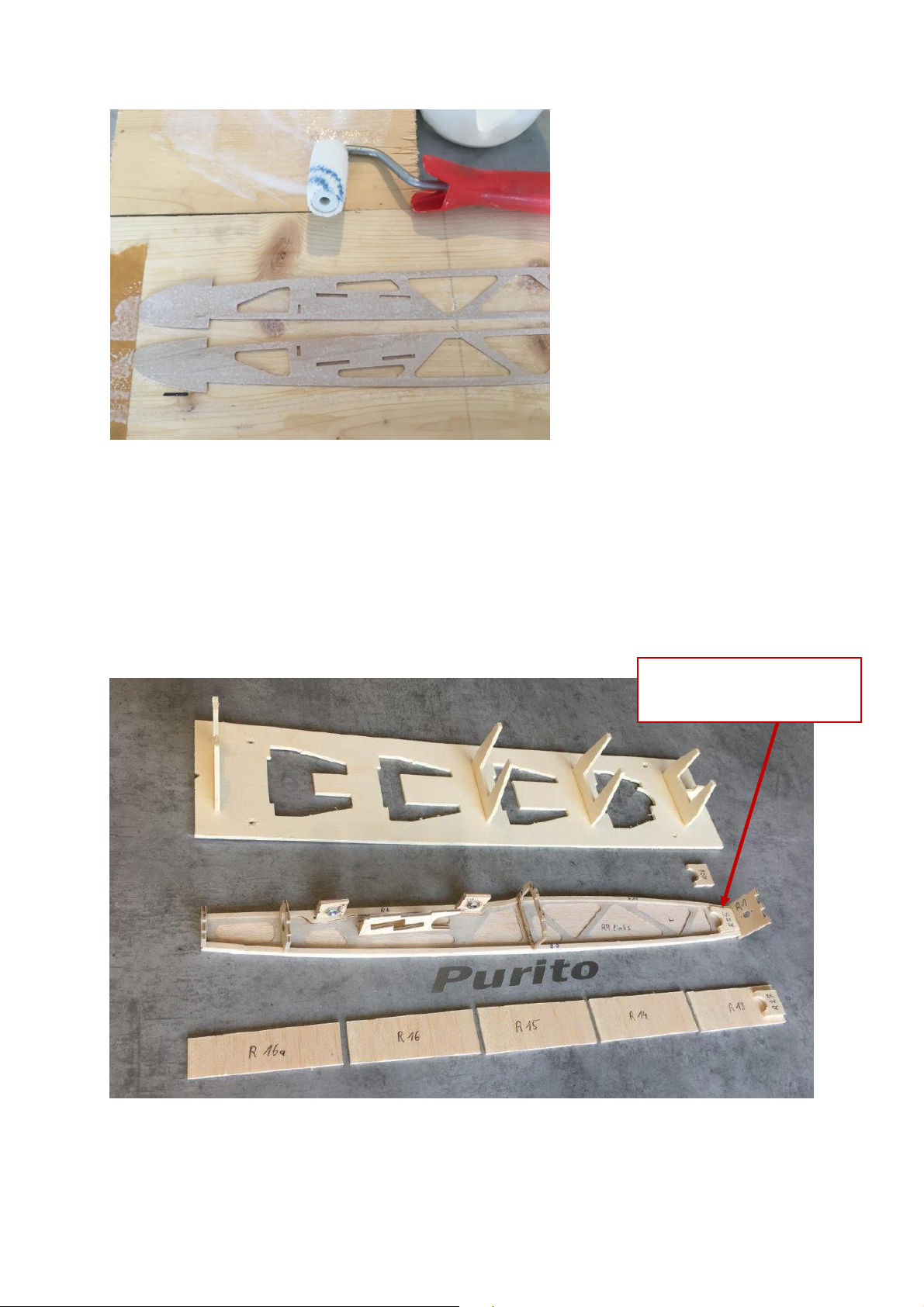
3
As shown in Fig. 3, we use a roller
Part R25 behind the
motor bulkhead
for gluing R9 and R10. This allows
the glue to be applied in an
evenly thin layer. Press the parts
together for several hours.
Glue the balsa strips R8 flush to the fuselage sides at the bottom.
Now glue the wing supports made of plywood R6 flush on the top of the fuselage sides. Take
care to remove any glue that may escape in the slots for holding the wing bolts.
In the canopy area, glue the plywood strip R7 flush with the fuselage, again paying attention
to left and right.
Frames R1 to R5 have a small notch on the top. The servo board R3 is marked on the leading
edge, as are the 4mm plywood parts (accessories bag). Now glue the two M5 nuts into the
4mm plywood parts of the wing bolts R11 and R12.
Two servo boards are included in the kit, one servo board with cutouts and one without. The
servo board with cutouts is intended for the HEPF H47 (rudder) and the KST X06 (elevator).
The second servo board without cutouts is intended for servos similar in construction, these
can be fitted individually.
Page 4

4
Now the fuselage can be test-fitted together.
The fuselage sides are assembled with all formers and the wing bolting and plugged into the
fuselage slipway.
Tip: We screw the fuselage slipway to our building board!
This ensures that it lies cleanly and the hull can be built up without distortion.
When all parts fit together properly in the slipway, they can be glued. Important here: frame
R5 must not be glued yet. In the same way, the parts of the wing bolts R11 and R12 are only
inserted into the slots provided for them, but not glued yet.
Now the hull boat can be taken
out of the slipway and inserted
with the bottom side facing
upwards.
This is followed by the lower
fuselage planking. We start with
part R13, which is glued to the
front of the fuselage (at the
motor bulkhead). Important
here: part R13 is slightly beveled
on one face due to the side draft.
Therefore, make sure that the
slanted side matches the motor bulkhead. Then parts R14 to R16a can be glued in place. For
part R16a, make sure that the fuselage bulkhead R5 is not glued down.
Page 5

5
Now parts R25 are glued to both sides of the fuselage, part R26 should be glued to the bottom
of the fuselage and part R27 to the top of the fuselage, centered between the two parts R25
(see picture). The parts R25-R27 are there to fit the fuselage to the spinner later.
On the top of the fuselage, glue the balsa part R17 between the canopy opening and the
engine bulkhead, here the wood grain runs crosswise.
Be careful here: part R17 is again beveled on one side due to the engine side pull.
Glue the two symmetrical plywood parts R19 into the canopy R18 in the holes provided.
Page 6
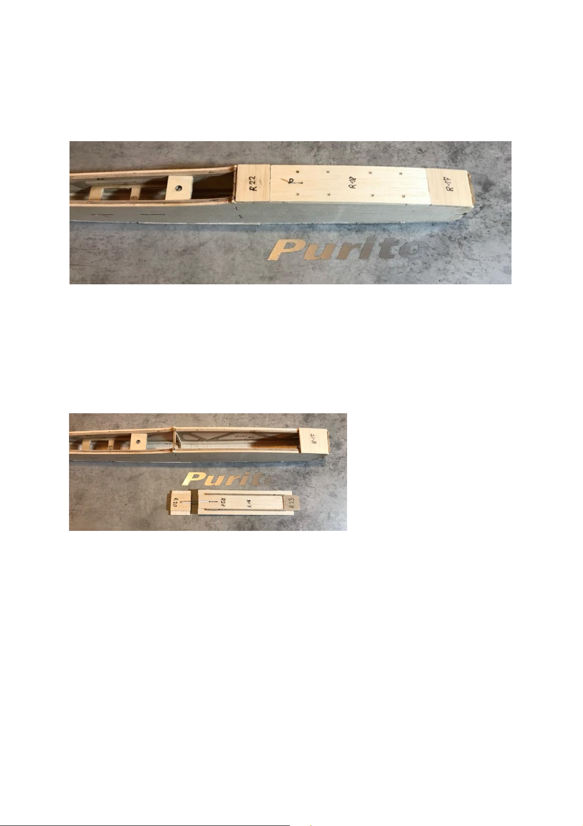
6
Make sure that the canopy reaches the necessary bend.
Tip: We carefully harden the slot in canopy R18 with liquid super glue. This prevents pressure
marks in the balsa wood caused by opening and closing the canopy.
The plywood part R23 is glued inside the canopy to the fuselage tip center, serving as a tongue.
Glue the balsa part R21 to the end of the canopy between the plywood strips. Bend a steel
wire into L-shape and glue it together into a Bowden cable into the inside of the canopy as a
fastener.
Then glue part R20 centrally on
the fuselage planking R22 and fit
it together with the canopy in
the canopy opening in the
fuselage.
Glue a piece of Bowden cable into the slot of R20 as a counterpart for the locking mechanism.
Tip: when gluing the Bowden cable into R20, place the canopy approx. 0.3mm underneath.
The goal is to position the bottom of the canopy slightly higher above the building board than
the counterpart of the latch (part R22).
Now the latch can be pushed into the breech position, put on the piece of Bowden cable and
glue it with R20.
By underlaying the canopy with 0.3mm, a tighter fit is created so that the canopy fits neatly
against the fuselage. Now part R22 can be glued to the fuselage.
Finally, the fuselage is roughly sanded together with the canopy.
Page 7

7
Fuselage tube and pylon:
69mm from the top of
the fuselage tube
22mm from the top of
the fuselage tube
The fuselage tube made of CFRP can be wet smoothed with water sandpaper. We recommend
a grit of 400 or finer here.
You will need: the 4 solid carbon rods with a diameter of 2mm, 2 each for the elevator and
rudder (accessories bag). Also, the parts P1 (10mm balsa), P2 (8mm balsa), P3 (3mm balsa)
and P4 (0.6mm) plywood) and the M3 nut.
First, the M3 nut is glued into
part P2.
The fuselage frame R5 is now
attached to the fuselage boom.
The upper side of the fuselage
tube is the side with the cutouts for the Bowden cables. Insert the 4 carbon rods, the two
shorter ones are for the pylon, these protrude about 22mm upwards from the fuselage tube.
The carbon rods for the rudder protrude approx. 69mm from the fuselage tube. Pay special
attention that the carbon rods are aligned with the axis center of the fuselage. Otherwise, the
finished tail will not be parallel to the fuselage axis. Tip: as shown in the picture, we align the
4 carbon rods all parallel on a wooden board and fix them with a weight. Then the hull boom
can be aligned exactly at 90 degrees to the individual carbon rods. You should take the
necessary time here, because the clean alignment of the carbon rods for the tail unit has a
significant influence on the flight behavior of the model.
When the carbon rods are correctly aligned, they can be glued in place.
The pylon part P1 can now be
fitted and glued in place. For
component P2, make sure that
the M3 nut points downwards.
Attach and glue the P2 and P3
components as well. Only part P4
must not be glued yet, because
this will be done later with the
elevator. The carbon rods that
protrude from the top of the
elevator pylon should be
shortened to 4.5mm (so that
they no longer protrude when
the elevator is screwed on)
Carefully grind the ends of the 4 carbon rods that now still protrude from the bottom of the
fuselage boom flat. Make sure that the fuselage tube itself is not damaged by the grinding.
Even minor damage will weaken the fuselage boom considerably.
Page 8

8
Rudder and elevator:
The 4mm balsa board with the
parts for the elevator and
rudder are needed for building.
The reinforcement part made of
4mm poplar plywood is in the
accessories package.
Additionally there are 3 parts
(S4-S6) for the rudder on the
8mm balsa board.
For the elevator, first press the 4mm plywood part from the accessory package flush into part
H2 and then glue it in place. The struts of the elevator have a bevel or a small rounding on one
side. This shows the correct position and alignment in the rudder.
We assemble the elevator as follows:
- First, we staple the parts shown on the protected construction plan (household foil)
and glue them with a drop of thin super glue.
- After that we insert the remaining struts and glue them in the same way
The same procedure is to be used for the rudder.
Here, too, we first staple the outline together and then work our way up from the bottom.
Tip: harden the holes in the rudder to accept the pins. To do this, insert a greased 2mm drill
bit into the hole and apply a drop of liquid super glue to it.
The construction of the tail unit is also explained in detail in our 4th tutorial:
https://www.youtube.com/watch?v=F4erVqr0to4
At the end we put the rudder on the fuselage tube and screw the elevator on the fuselage
pylon. To do this, we apply a little white glue to the fuselage pylon and glue the P4 support
extension to it.
Again, make sure that the angle of elevator and rudder is exactly 90 degrees.
Tip: when gluing, a lightly greased M3 steel screw helps to prevent it from sticking in the
thread.
We will go into more detail about sanding the tail plane in a later point.
Page 9

9
Assembly of the fuse:
Rudder and elevator
90 degrees
Elevator and auxiliary
rail parallel
Insert R5 and fix it with
a clamp
Support 1cm before
the end of the pipe
Now the fuselage tube can be joined to the fuselage boat.
The wing support is checked once again for protrusions to ensure a flat support surface for
the wing center section.
Page 10

10
A straight line is drawn on the building board, extending along the entire length of the hull.
Fuselage tube
protrudes 2mm above
Straight side points
upwards
The fuselage tube is inserted into the fuselage boat so far that it protrudes 2mm from frame
R4.
The frame R5 is inserted into the rear of the fuselage boat. 1cm before the end of the fuselage
boom the support made of 3mm balsa is inserted.
On the rear surface screw connection, a straight strip with a length of approx. 40cm, in an
angle of 90 degrees to the fuselage center line is screwed on (this serves us as an assistance
for the alignment).
Now all parts can be aligned, parallel to the drawn line. The fuselage tube lies neatly in the
holder, the fuselage lies flat in the fuselage slipway.
The elevator lies parallel to our screwed-on auxiliary rail. The fuselage side panels are pressed
to frame R5 with clamps. Before gluing, check again for correct alignment.
The fuselage must lie without tension in its slipway and end support.
Only a correctly aligned fuselage ensures optimum flight characteristics.
The final work on the hull now includes the transition from the hull boat to the hull tube,
which is done with the two parts R24. These are fitted to the end of the fuselage boat and
glued with the straight side facing upwards.
Page 11

11
Sanding of fuselage and tail unit:
When sanding the fuselage we start as just mentioned with the transition from the hull boat
to the hull tube. While doing this the hull tube should be covered with tape to avoid damage
caused by grinding. Attention: if the CFK tube of the fuselage is damaged by sanding a
predetermined breaking point is created at this position.
Firstly the end of the fuselage is adapted to the contour of the fuselage. We use a 150 grit
sanding board (as shown in the picture below). Tip: Sanding boards can also easily built from
the balsa residues, to which we stick the sandpaper.
In order to get smooth curves on the desired fuselage edges we first grind 45° phases. These
phases are easier to control for evenness and help us to maintain a clear radius.
When the desired fuselage shape has now been created all wooden parts are sanded again
with a finer sandpaper (grain approx. 240) to get a smoother surface.
Tip for sanding the tail unit:
We stick a piece of sandpaper
over the entire length of the tail
unit on a wooden plate.
The tail unit is placed on top of
this, as can be seen in the
picture.
As a result the tail unit can’t slip
away and can now be sanded
with another sanding batten.
Thereby remaining super glue
spots can be removed from the
surface.
After that an auxiliary line is drawn in the middle on the elevator and rudder along the
trailing edge.
As you can see in the picture, we
put the rudder on an 8mm thick
plywood. When sanding the
rudder with a sanding board,
make sure that the sanding
board rests on the trailing edge
of the tail unit and the edge of
the table. So we grind the
trailing edge to a point from
both sides (approx. 1mm) up to
our auxiliary line. In contrast to
the trailing edge, which we have
just sharpened to a point, we
are grinding the leading edge of
the tail units round.
Page 12

12
For this we grind a 45° phase on both sides of the leading edge of the tail unit which takes up
about a third of the wood thickness. This phase in helps us to grind an even curve over the
entire edge curve. When sanding the rounding make sure that a rounding actually occurs at
the end. A tapered leading edge of the tail unit would affect the flight characteristics
negatively.
At the end only the bevel for the rudder deflection is missing. With the elevator the bevel is
on the underside of the rudder with the rudder on the left side, where the control horn will
later be located.
The slope in the elevator must be sufficient to achieve a downward deflection of at least
12mm. The rudder must have a deflection of at least 45 degrees in both directions.
We also explain the grinding of the tail unit in detail at the end of our 4th tutorial:
https://www.youtube.com/watch?v=F4erVqr0to4
Page 13

13
Installation of the pushrod (Bowden) tubes:
To achieve a secure gluing of the Bowden
tubes in the fuselage tube, we proceed as
follows:
A 0.8mm steel wire is inserted into the
bowden tube which must be about 2cm back
at the rear end of the Bowden tube. This
protrusion of the Bowden tube over the steel
wire is important that the steel wire doesn’t
stuck in the Bowden tube later.
The Bowden tubes are placed into the fuse
tube and fixed to the inside wall of the fuse
with the help of magnets.
Tip: the position of the Bowden tubes at the
end of the fuselage boom is already given by
the milled openings. In the fuselage it is
important to ensure that the Bowden tubes
are designed to match the used servos.
Now approx. 15 drops of liquid superglue can
be dripped along the Bowden tube into the
inside of the fuselage tube. The superglue
runs down the Bowden tube to the end of the
fuselage tube and glues it over its entire
length. To do this the fuselage must also be
held vertically when gluing.
Note: it is advisable to put a piece of
newspaper on the floor as the superglue can
drop out of the pipe.
Page 14

14
Description wings:
We will start with panel C:
On the picture you can see the
needed parts: Base plate,
matching ribs for part C, edge
bow, 5 degree stop, end bar,
comb, 7mm CFK tube (spar) and
the 2mm CFK tube (leading
edge).
I lightly sand the CFK tubes with
200 water sandpaper and clean
them with a degreasing agent.
The retaining webs from the ribs
are to be removed as cleanly as
possible after cutting. This saves a lot of sanding work in the end and the profile is preserved
exactly.
One more note about the base
plate: The foot at the end strip
of the rib determines the
position.
Afterwards, the ribs of part C
can be placed on the cut-to-
length CFK tube (7mm diameter,
262mm length). The CFK tube
should still protrude by about
7mm at the edge bend. The ribs
are aligned with the combs.
Then they can be inserted into
the template for the feet of the
ribs in part C
(please make sure that the leading edge points in the right direction).
Important here: The building aid must lie flat on a straight building board (preferably
screwed on directly). Now make sure that the alignment is correct and that the ribs are fully
inserted in the template. The rib C1 is placed with the stop on a slope of 5 degrees.
Page 15
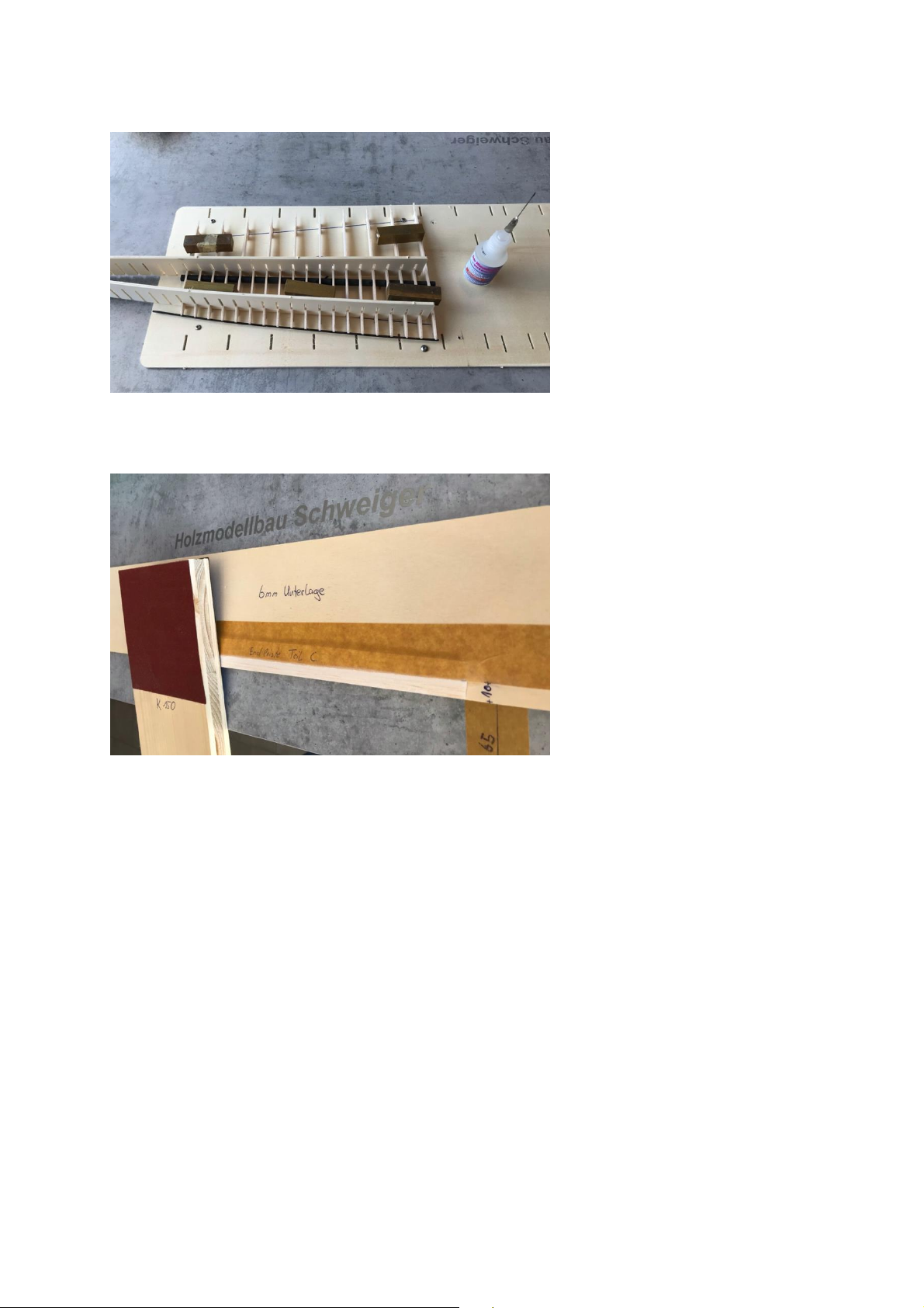
15
At the end we check again the
correct alignment of all ribs and
glue all whole ribs (not the half-
ribs) to the tube. Tip: for correct
alignment we use weights to fix
the wing part neatly.
We use a thin liquid super glue
for gluing.
For the leading edge we use the
2mm CFK tube, which is
carefully inserted into the
cutouts provided for it.
After that, the half-ribs can also be neatly aligned and glued again with the comb.
The end strips are ground before
installation. To do this, place the
first and last ribs on the end
strip and mark the end of the
ribs on it.
Our two markings are now glued
on with masking tape at the
same distance. Here, the end
strip should be flush with the
edge on a plywood. Tip: We use
as a rule of thumb 1mm
underlayment corresponds to
about 1cm distance from the
edge of the table. So in our case, with an underlay of 6mm, this corresponds to a distance of
6cm between the end strip and the edge of the table.
Tip: When the end strip is almost finished sanding, remove it from the carpet pad and soak
the back 5mm with liquid super glue and then finish sanding. After soaking, the end strip
should only be carefully sanded once more so that you don't take away too much material.
We recommend a thickness of 1mm at the end.
If you now turn to the second end strip, make sure that you need a left and right end strip.
Page 16
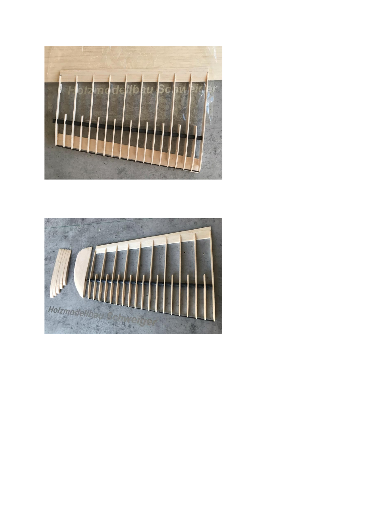
16
For the end strips (sash part
A,B,C), sanding is performed on
a base of 6mm at a distance of
60-65mm from the edge of the
table. This distance is the same
for all end strips of the wing.
The finished ground end strip is
fitted flush onto the ribs from
behind, at the bottom. This is
done with the intention of a
tight fit. As you can see in the
picture, the wing part is
shimmed 2mm in the front
(under the feet of the ribs) and
8mm in the back, so that the end strip lies neatly in the profile.
We also explain end strip sanding in detail in our 1st tutorial:
https://www.youtube.com/watch?v=hPf9JKf5TbM
The parts for the edge bow (1-5)
can be found in the 8mm balsa
board. These can be glued
together according to personal
taste, we use an offset at the
end strip of about 2mm. Tip:
protect the building board here
with a piece of household foil,
place the parts of the edge bow
with the straight underside and
glue them together.
The glued edge bow is attached to the protruding carbon spar and adapted to the wing
shape. First, sand the edge bow and then glue it to the wing ear.
When building the second wing part, make sure that this part is built mirror-inverted! (left
and right wing ear, turn base plate for this).
Page 17

17
The wing panels B are built up in
the same way as the wing panels
C.
The only difference is that here,
a 7mm aluminum tube must be
glued in as a surface connector,
too. Also, make sure that both
the root rib and the end rib are
slanted 5 degrees.
Important: grind the aluminum
tube of the wing connector
before gluing it in order to
create a rough surface. This is
the only way to ensure secure
bonding. In addition, the
aluminum tube is closed with a
small plywood circle from the
base plate.
In this picture, the wing mating
and the small reinforcement on
the leading edge are already
glued in place.
Caution here: the leading edges
in panel A and B are 2.5 mm
thick. (In contrast to panel C:
here it is only 2mm thick).
The wing part B is again
underlaid at the leading edge
with 2mm (under the feet of the
ribs) and at the trailing edge
with 8mm. This allows the end
strip to be glued on without
distortion. At the end, the large
reinforcement between rib B1
and B4 is glued in place.
The reinforcements are made of
3mm poplar plywood.
These reinforcements will help
us later to string the wing
without distortion.
Page 18

18
Wing panel A:
All ribs are carefully cut out from the building board and cleaned. We start in the center with
ribs A1 (2mm plywood). These are threaded onto the cut-to-length CFK tube (12mm
diameter, 695mm length). Then the remaining ribs follow in order of designation. All ribs are
inserted into the template together with the two end ribs A25.
Tip: take enough time with such
a large number of ribs to align
them neatly with the combs on
the base plate. The end ribs A25
must again be inclined 5 degrees
with the template.
The gap between the two ribs
A1 in the center is larger than
the gap of the remaining ribs. As
a result, the comb does not fit
into this gap either. In order to
align the ribs at a 90 degree
angle to each other, we clamp
the relining to the surface screw
A2V (8mm balsa board) between
the ribs using a clamp. Thus, the two ribs are fixed vertically.
Now the remaining ribs can also
be aligned. They are then glued
to the spar. After this step, the
leading edge (CFRP tube 2.5mm)
can be attached to the front.
Note that the comb must be
shortened by one field to align
the ribs. This is because the root
rib is now at an angle of 5
degrees and thus the comb no
longer fits over a complete half
of the center section.
To fit the leading edge now, we place one comb just behind the leading edge and the other
just behind the spar. This allows the ribs to be aligned at 90 degrees to the spar. We weigh
down the ribs with weights to push them all the way into the base plate.
Now we start to press in the leading edge at the root rib A25. Rib by rib, the leading edge is
now threaded towards the center.
Tip: Once approx. 15 ribs have been threaded on, the leading edge can be glued to the root
rib. This simplifies further threading.
Page 19
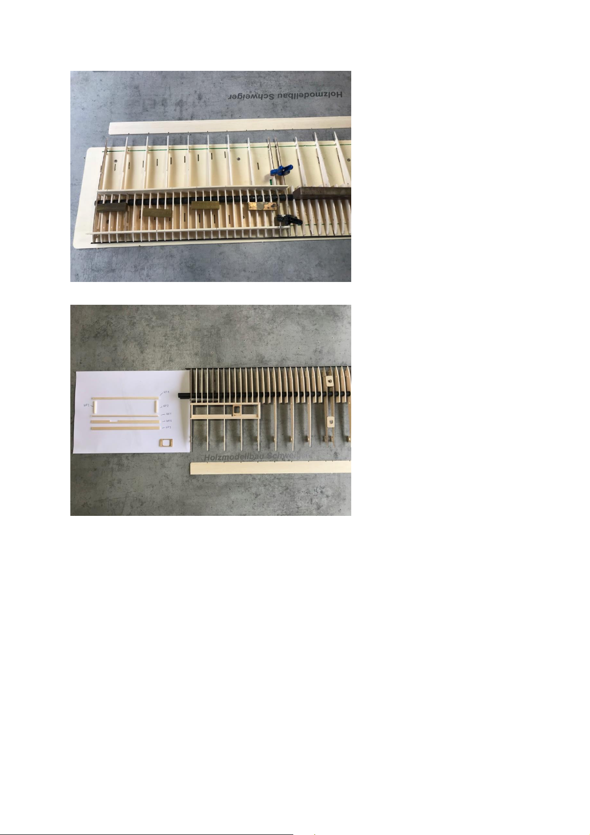
19
After that, the two plywood
KF1
KF2
KF3
KF1
KF3
KF2
Servo frame
pieces A1V (for the surface
screw connection) can be
placed. These belong in the
recess of the plywood ribs A1.
The top side is marked by the
recess for the screw head.
Then glue it in place.
The aluminum plug-in tube is
closed again on one side with
the plywood circle and also
glued in place.
The next step is the border for
the flaps in the wing. The parts
KF1-KF2 from the 3mm, and the
two strips KF3 from the 2mm
balsa board are needed. KF3 can
be found on the balsa board of
the ribs (part A). Note here that
there are two different versions
of KF3: one with the cutout for a
servo frame, and one without
the cutout. The parts are
inserted into the surface in the
recesses provided for this
purpose and glued. The short
KF2 strips are always glued to
the center of the wing (see picture), otherwise there is no room for the airbrake. Important
here: as shown in the picture, KF1 is glued lying towards the leading edge and standing
towards the trailing edge. The center section should remain on the base plate for this build
step to prevent possible warpage. We have removed the center part from the base plate
only for the picture.
The ground end strip is glued to the wing as in part B. To do this, take the center section
from the base plate and place it under the feet of the leading edge strip with 2mm and on
the trailing edge strip with 8mm. Then glue the end strip to wing part A.
Page 20
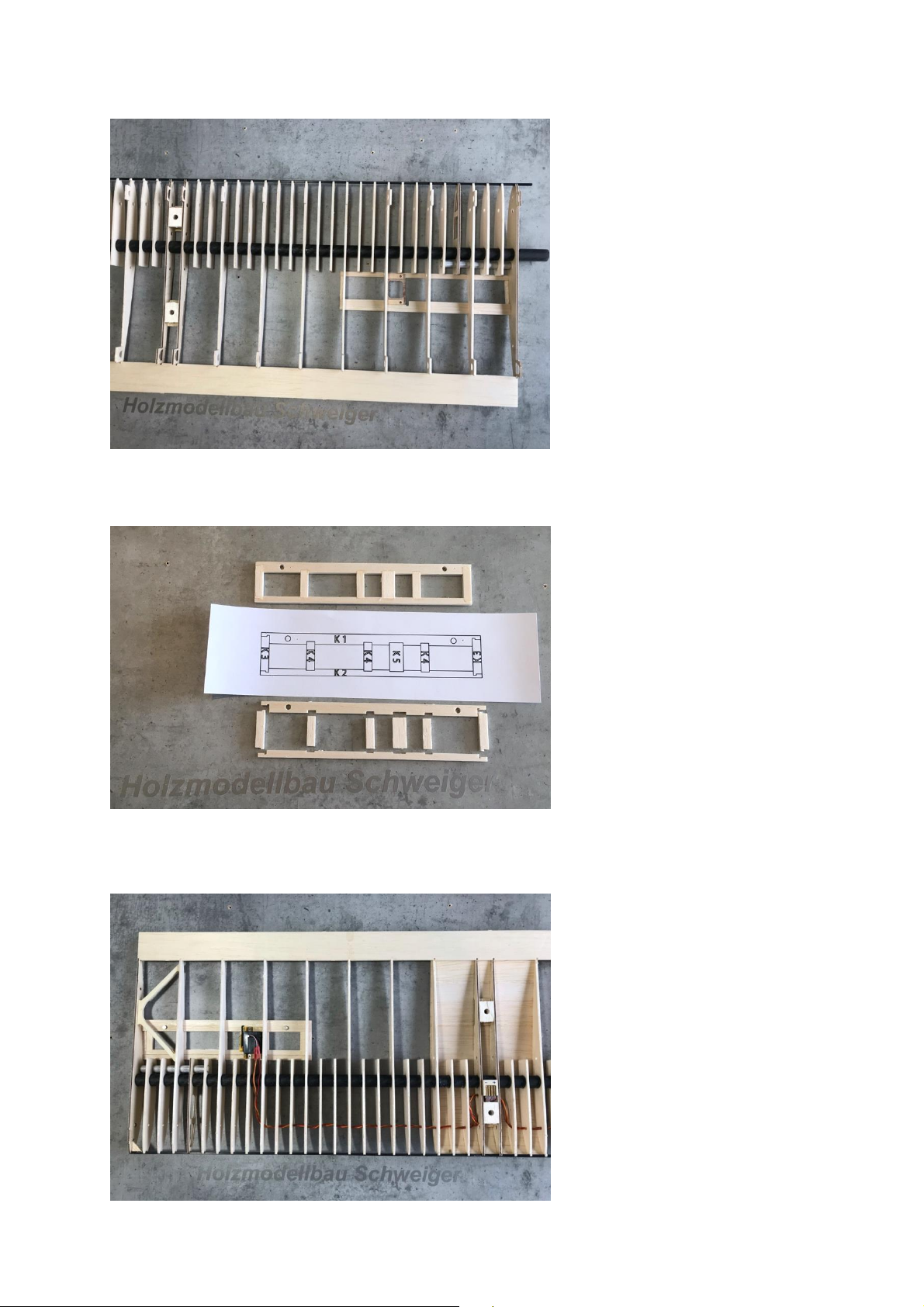
20
The component A2V is located
on the 8mm balsa board and is
glued under the plywood part
A1V and pierced flush. Tip:
insert a drill with a diameter of
5mm through the balsa blocks
A2V when gluing so that the
holes are exactly on top of each
other.
The upper planking (1.5mm
balsa) is adjusted to the leading
edge and shortened by about 2-
3mm at the end. The shortened
end of the planking is sanded at
an angle to match the profile.
Tip: we sand about 13mm wide for this and the trailing edge down to 0. When the planking
matches the profile of the center section, it is tacked to the leading edge. Then quickly apply
a thick super glue to the two plywood ribs and the end strip. The planking can now be
pressed on, along the remaining
ribs we glue the planking from
below with thin super glue. Now
all support feet and the
protruding tubes at the root ribs
can be removed. Depending on
how the center section is to be
removed, the cables for the
servos can now be routed.
Assemble the parts for the
airbrakes on the plan and then
glue them together with liquid
super glue. Then fit the airbrake
into the recess in the center section.
Finally, the magnets (diameter 4mm) must be glued to the underside, flush in the holes
provided for them in the
airbrake. The flap is inserted into
the wing. The magnets can now
be placed on the underside of
the KF3 component. The
magnets now align themselves.
This means that the remaining
magnets from the underside of
the wing can also be glued. The
magnetic attraction force is thus
already sufficient in this version.
If a higher attraction force is
required, the magnets can be
embedded a little deeper.
Page 21

21
Should our solution be used for
the flap opening, a servo arm
extension is required. For the
servo arms we recommend our
GFK extension, which is available
as an accessory together with
the matching servo frames..
We also have a video for the
functional mode:
https://youtu.be/d9o5HwRrMTI
We use a 5-pin spring contact
for the power connection to the
fuselage. This is also available
from us as an accessory. As you
can see in the picture, these
accessories also include milled
plywood parts that fit the spring
contact accurately into the wing
mount.
Soldering experience is required for this design.
In the next step, the lower planking of the center panel can be attached. To do this, the
planking must be adjusted to the leading edge and glued in place. When the planking neatly
matches the profile of the wing, it can be glued to the underside of the ribs.
Page 22

22
To prevent twisting of the wing
ears on the center section, the
accessory package includes
dowel pins with a diameter of
2.5mm made of CFK.
These pieces are slightly
sharpened with sandpaper and
inserted into the wing center
part. Now the ear can also be
pinned on, but with a small gap
to the root rib.
Tip: we put a 2mm balsa rest between the middle part and the ear and fix them together
with two clamps. The ear can now be neatly aligned with the center section on the
underside. The best way to tell if the two parts are exactly aligned is to look at the underside
of the wing. If this is the case, the pins are glued to the inside of the root rib (middle part).
Now the ear should be easily removable. To further secure the pins, there are small plywood
washers on the rib board. These are also glued to the inside of the root rib (center section),
on top of the CFK pins.
If these connections fit neatly, the wing parts B and C can now be glued together. For this
purpose, use the milled, 2mm GRP connector in the accessories package. The connector is
fitted into the CFK tubes and then glued vertically.
The model is now ready for assembly. The final steps include screwing the wing onto the
fuselage. To do this, the lower planking must be drilled through at the location of the wing
screws. Tip: again, these edges can be hardened with liquid super glue.
Once the wing is screwed to the fuselage, all angles from the wing to the tail unit are
checked again. If these angles match, it is important to glue the still loose wing screw
connections in the fuselage (4mm plywood pieces). This step is especially important because
the glued wing bolts contribute significantly to the stiffness of the fuselage.
Before covering, make sure that all support feet and retaining webs of the milled parts are
cleanly removed and that no unevenness interferes with the profile.
When covering the wings, it is particularly important to stretch the film evenly on both sides
of the model. It is also important to ensure that both sides of a wing are subjected to an
even tension.
If this is not the case, the wing will twist in itself and thus negatively affect the flight
characteristics of the model.
We recommend ORACOVER light foils for covering the Purito.
Page 23
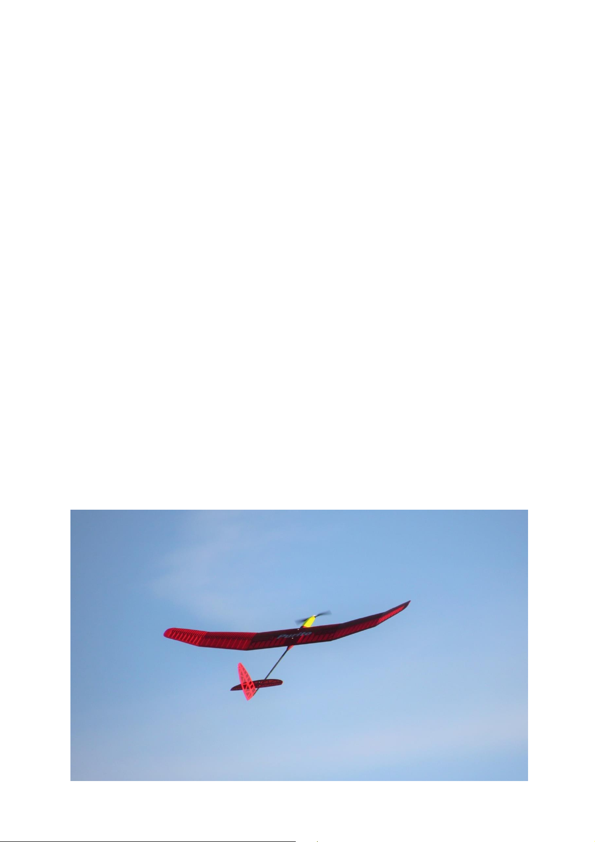
23
When the model is finished covering, the GFK rudder horns must be glued into the milled
holes provided for this purpose. The longer rudder horn is for the elevator, the shorter one
for the rudder. The linkages are to be attached in the outer holes of the rudder horns, since
in such a way an optimal rudder deflection can be achieved.
You can now also screw in the launch hook and install the remaining RC components.
RC components:
We used the following components for our test models:
- Drive: Hacker A10 with gearbox
- Regulator: Pichler Pulsar A-15
- Battery: 3s 450 mAh
- Elevator servo: KST X06
- Rudder servo: Hepf H47 or KST X06
- Airbrake servos: Hepf H47
Of course, other components can be used, but then the motor bulkhead or servo board may
have to be adjusted.
Basic settings before the first flight:
- Center of Gravity: for the first flight, a center of gravity of about 75mm (measured from the
leading edge of the wing) should be selected.
- Rudder deflections: Elevator +/- 1cm, rudder 45 degrees, airbrakes maximum deflection 90
degrees (add a little elevator to the airbrakes about 10% of the total deflection).
Note: for the first flights, light hand throws are advisable to find the correct rudder settings.
The building instructions give you a suggestion how to assemble the model. However, if you
have any suggestions or ideas for improvement, we would be happy to receive feedback
from you.
We wish you a lot of fun with your finished E-Purito and a good flight all the time!
 Loading...