

HOLZMANN MASCHINEN ED 400FD Instruction Manual
HOLZMANN-MASCHINEN GmbH
Marktplatz 4 · 4170 Haslach · Austria Gewerbepark 8 · 4707 Schlüsslberg · Austria
Telefon +43.(0) 7289.71562 -0 Telefon +43.(0) 7248.61116 -0
Telefax +43.(0) 7289.71562 -4 Telefax +43.(0)7248. 61116-6
Email info@holzmann-maschinen.at www.holzmann-maschinen.at
www.holzmann-maschinen.at
Revision 3/ 06.05.2011
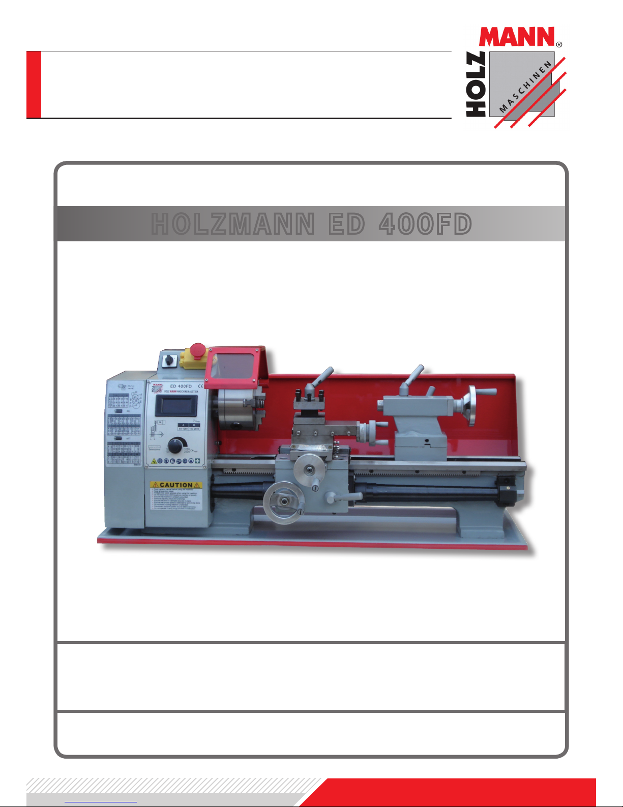
HOLZMANN ED 400FD
DEUTSCH ENGLISH

www.holzmann-maschinen.at
Dear Customer!
This manual contains Information and important instructions for the installation and
correct use of the metal lathe ED 400FD
This manual is part of the machine and
may not be stored separately from the
machine. Save it for later reference and
if you let other persons use the machine,
add this instruction to the ma-chine.
Please read and obey the security instructions!
Before rst use read this manual
carefully. It eases the correct use
of the machine and prevents misunderstanding and damages of machine and the
user’s health.
Due to constant advancements in product
design and construction pictures and content may di-verse slightly. However, if you
discover any errors, inform us please with
the product feedback form.
Technical specications are subject to
changes!
Copyright © 2011
This document is protected by international copyright law. Any unauthorized duplication, translation or use of pictures,
illustrations or text of this manual will be
pursued by law – court of jurisdiction is
A-4020 Linz, Austria!
Sehr geehrter Kunde!
Diese Bedienungsanleitung enthält Informationen und wichtige Hinweise zur Inbetriebnahme und Handhabung der Metalldrehbank ED 400FD
Die Bedienungsanleitung ist Bestandteil
der Maschine und darf nicht entfernt werden. Bewahren Sie sie für spätere Zwecke
auf und legen Sie diese Anleitung der Maschine bei, wenn sie an Dritte weitergegeben wird!
Bitte beachten Sie die Sicherheitshinweise!
Lesen Sie vor Inbetriebnahme diese Anleitung aufmerksam durch. Der sachgemäße
Umgang wird Ihnen dadurch erleichtert,
Missverständnissen und etwaigen Schäden wird vorgebeugt. Halten Sie sich an
die Warn- und Sicherheitshinweise. Missachtung kann zu ernsten Verletzungen
führen.
Durch die ständige Weiterentwicklung unserer Produkte können Abbildungen und
Inhalte gering-fügig abweichen. Sollten
Sie jedoch Fehler feststellen, informieren
Sie uns bitte über E-Mail oder Fax mit Produktinformationsformular am Ende dieser
Anleitung.
Technische Änderungen und Irrtümer vorbehalten!
Urheberrecht © 2011
Diese Dokumentation ist urheberrechtlich
geschützt. Die dadurch verfassungsmäßigen Rechte bleiben vorbehalten! Insbesondere der Nachdruck, die Übersetzung
und die Entnahme von Fotos und Abbildungen werden gerichtlich verfolgt – Gerichtsstand ist A-4020 Linz, Austria!
ENGLISH
DEUTSCH
1
4
2
3
5 6
7 8 9
www.holzmann-maschinen.at
19
10 11 12
13 14 15
16 17 18
20
21 22
www.holzmann-maschinen.at
26 27 28
29 30 31
32 33 34
35 36
37
38 39
40
42
41

www.holzmann-maschinen.at
1. GENERAL SAFETY RULES
Read and understand the owner’s manual and labels afxed to
the machine. Learn its application and limitations as well as the
specic potential hazards peculiar to it.
Keep working area and the ground clean and free of oil and other
materials!
Assure that the working area is sufciently lighted!
Don’t use the machine outside!
The use of the machine is forbidden if you are tired, not concentrated as well if you are under the inuence of medicaments, alcohol and other drugs. Reduce distraction sources in the working
area.
BEWARE: Routine leads to insufcient attention.
The machine shall be used only by trained persons wiht an age
of at least 18 years.
Non authorized personnel, especially children, shall be kept away
from the machine! Make your workshop childproof.
When working with the machine, don’t wear loose clothing, long
hair openly or loose jewellery like necklaces etc. Loose objects
might be catched by rotating parts and cause serious injuries.
Use proper safety clothing and devices when operating the machine (safety glasses, ear protectors)!
Assure yourself that your feeding current complies with the requirements of the motor - check the typeplate.
Electric checks and the electric installation of the machine may
only be performed by a qualied electrician.
DO NOT touch leading machine parts.
Prior to any Cleaning, Check, maintenance or tool change shut
the machine off and disconnect it from the power supply in order
to prevent unintended start up of the machine.
READ THE MANUAL
AVOID DANGEROUS CONDITIONS
OPERATOR
CLOTHING
SAFETY EQUIPMENT
ELECTRIC CONNECTION
ENGLISH

www.holzmann-maschinen.at
MAINTAIN SAFETY GUARDS, COMPONENTS AND SIGNS
NEVER FORCE YOUR MACHINE
DO NOT OVERREACH
SECURE SMALL WORKPIECES
MAINTAIN TOOLS WITH CARE
It will do a better job if used at its designed output rate.
Forcing your machine shortens it`s lifespan, may cause machine
defects and poses a security risk.
Keep proper footing and balance at all times.
When processing small workpieces, x them with a suitable device like a vice, downholder, to avoid accidents.
Do not x or feed small workpieces by hand.
Keep your hands away from dangerous area, allways guide the
workpiece or tool securely.
Assure yourself to keep your working tools always sharp and in
best working condition.
Defect or blunt tools pose a security risk.
Assure yourself, that all safety guards and safety devices of your
machine are working in best condition. Damaged Safety guards
have to be repaired before using the machine again.
Check the function of the machines Safety components like
Emergency OFF Buttons and Disconnectors in regular intervals.
Defect Safety components have to be replaced immediately.
Check the condition of the Safety signs and operation rule plates
on your machine. Replace missing or non-readable ones.
Before leaving the machine, shut it off and wait until the motor
and all rotating parts stop.
Form a habit to check that there are no tools, keys, wrenches ...
on the machine/tool before you start the machine.
Remove all accessories and tools from the machine before you
switch it on.
NEVER LEAVE MACHINE RUNNING UNATTENDED
REMOVE UNUSED TOOLS, KEYS, WRENCES
ENGLISH

ENGLISH
This metal turning lathe shall be used expicitly for turning and
drilling of metal and plastic materials suitable for chip removal.
The processing of other materials is not allowed!
never process magnesium - Burn Hazard!
Besides the information of this manual and the specic work safety rules valid in your country you should be familiar (through
proper education & experience) with the specic operation, safety and processing rules that have to be obeyed when working
with a metal lathe.
Do not wear gloves when working with the machine.
It might be catched in rotating parts and cause severe injuries.
Comply to the rules of max. workpiece diameter, length etc ...
Always check the fastening tool to be mounted properly so that
it cannot become loose.
Check the workpiece for being fastened correctly.
Use the lathe chucks within the frame they are designed.
Do not attempt to fasten workpieces with diameters that do not
match with the chuck. Do not overfasten the chuck.
Process only short workpieces without tailstock.
Additionally, if the workpiece length is more than 3 times the
workpiece diameter, the workpiece has to be secured with the
tailstock as well by all means.
Avoid the combination of short fastening diameters with big
machining diamterers.
Avoid short fastening lengths
Always be informed about the technical limitations of your tools.
Especially - never use a tool at turning speeds that lie above the
max. alowed turning speed of the tool.
Perform tapping, threading in general and the machining of non
centrally fastenend workpieces only at slow turning speeds.
2. SPECIFIC RULES
CORRECT USE
OBEY THE SPECIFIC WORK RULES FOR METAL LATHES

www.holzmann-maschinen.at
The workplace must have:
sufcient lighting conditions to prevent
shadows or eye strain.
a clean, level underground that is vibration resistent! We strongly recommend to
install the the metal lathe onto a solid,
vibration-resistent workbench.
enough place around the machine for safe
handling and feeding of the material.
A proper, compatible electric supply circuit.
Humidity: max. 90% for max. 25°C
max. 70% for max. 40°C
height above sea level: max. 1000m
Do not use the machine outdoors.
Do not use the machine in workplaces
with explosion and re hazard.
The work with a metal lathe always contains a certain risk that can never be eliminated entirely. This is a non complete shortlist indicating some of the most
dangerous remaining residual risks:
Risk of personal injury due to coming into
contact with the rotating workpiece or
rotating chuck.
Risk of personal injury through chips -
wear safety goggles.
Risk of electrocution when touching leading machine components.
Risk of personal injury by touching sharp
workpiece edges.
You can minimize these residual risks by
following all security, maintenance and
operation rules.
WORKPLACE REQUIREMENTS INAPPROPRIATE MACHINE USAGE
RESIDUAL RISKS
Any use that does not comply with the
security rules, maintenance guidelines or
operation rules described in this manual.
Any use that does not comply to max.
workpiece dimensions, max. turning
speed or other technical limitations.
The use of the machine by not sufciently trained persons in general.
HOLZMANN Maschinen cannot be made
liable for any damages to machine and
person being a direct or indirect consequence of inproper use of the machine.
ENGLISH

3. MACHINE SETUP
Remove the wooden crate around the lathe.
Check the contents of the shipping container:
ED 400FD metal lathe
Test Flow Chart
Toolbox
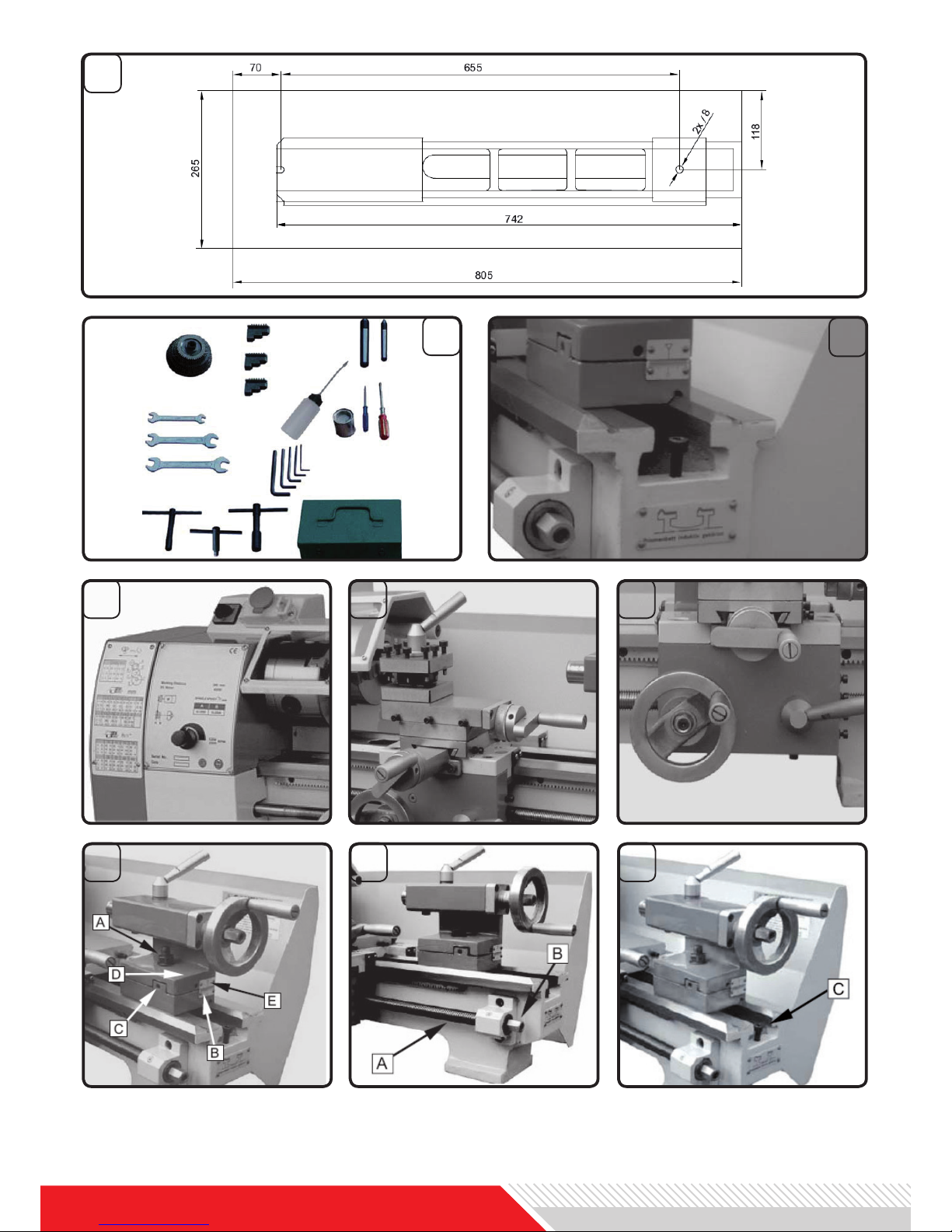
Contents of the Toolbox:
See Figure 2
1 Dead center MT3
1 Dead center MT2
3 External Jaws
1 Oil gun
1 Cross screwdriver
1 Flat screwdriver
1 Key for 3-Jaw chuck
5 Hex Socket wrenches
3 Double End Head Wrenches
1 Change Gears
Unbolt the lathe from the shipping crate
bottom.
Choose a location for the lathe that:
fulls all requirements from the security
section.
With adequate lifting equipment, slowly
raise the lathe off the shipping crate bottom.
DO NOT LIFT the machine by a spindle.
Make sure that the lathe is balanced before lifting it.
Lifting has to be performed by respectivel
trained persons.
ATTENTION
!
Read and understand the security and
Machine setup sections of this manual
before attempting to set-up the machine.
Failure to do so might result in machine
damage or even serious injuries!
CHECK DELIVERY CONTENT
SETTING TO WORKPLACE
To avoid twisting the bed, the lathe`s lo-
cation must be absolutely at and level.
Bolt the lathe to the stand (if used). If
using a bench, through bolt for best performance. Check Figure 1 for the boring
hole distances.
Clean all rust protected surfaces using
a mild commercial solvent, kerosene or
diesel fuel. Do not use paint thinner gasolone or lacquer thinner. These will damage painted surfaces. Cover all cleaned
surfaces with a light lm of 20W machine
oil.
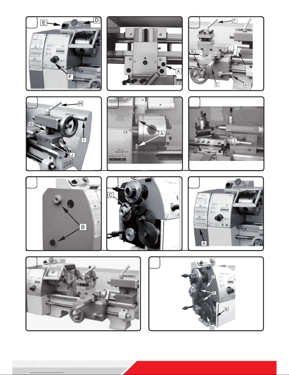
Remove the end gear cover. Clean all
components of the end gear assembly
and coat all gears with a heavy, non-slinging grease.
Lubricate the machine at all lubrication
points and ll the oil reservoirs to operating level before placing the lathe into
service!
Instructions for lubrication can be found
in the maintenance section of this manual.
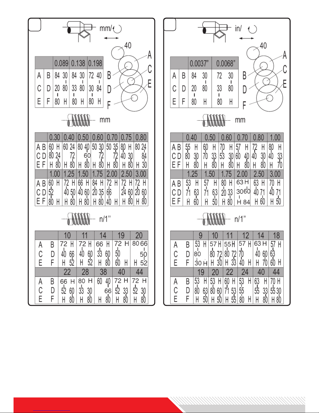
LUBRICATE ALL SLIDEWAYS LIGHTLY
BEFORE EVERY USE. LUBRICATE THE
CHANGE GEARS AND THE LEADSCREW
SLIGHTLY WITH A LITHIUM-BASED GREASE.
ENGLISH

www.holzmann-maschinen.at
4. MACHINE DESCRIPTION
The ED 400FD is a High Quality metal
turning lathe, especially designed for the
sophisticated private user but as well
for professional workshops requiring the
machine for processing small to middle
workpieces.
The lathe bed is made of high-grade iron
with low vibration and rigidity. It integrates the headstock and drive unit, for attaching the carriage and leadscrew. The
two precision-ground V-sideways, reenforced by heat hardening and grinding,
are the accurate guide for the carriage
and tailstock. The main motor is mounted
to the rear of the left side of the bed.
The headstock is cast from high grade,
low vibration cast iron. It is bolted to the
machine bed with four screws. The headstock houses the main spindle with two
precision taper roller bearings and the
drive unit.
The main spindle transmits the torque
during the turning process. It also holds
the workpieces and clamping devices
(e.g. 3-jaw chucks)
The carriage is made from high quality
cast iron. The slide parts are smoothly
ground. They t the V on the bed without
play. The lower slide parts can be easily
and simply adjusted. The cross slide is
mounted on the carriage and moves on
a dove tailed slide. Play in the cross slide
may be adjusted with the gibs.
Move the cross slide with the handwheel.
A four way tool post is tted on the top
slide and allows four tools to be clamped.
Loosen the center clamp handle to rotate
any of the four tools into position.
The apron is mounted on the bed. It
houses the half nut with an engaging lever for activating the automatic feed.
LATHE BED - FIG. 3
The half nut gibs can be adjusted from
the outside.
A rack, mounted on the bed, and a pinion
operated by handwheel on the carriage
allow for quick travel of the apron.
The leadscrew A is mounted on the front
of the machine bed. It is connected to
the gearbox at the left for automatic feed
and is supported by bearing on both ends.
The hex nut B on the right end is designed to take up play on the leadscrew.
The tailstock slides on a V way and can
be clamped at any location. The tailstock
has a heavy-duty spindle with a morse
taper MT2 socket and a graduated scale.
The spindle can be clamped at any location with a clamping lever. The spindle is
moved with a handwheel at the end of
the tailstock.
Fit the securing screw C at the end of the
lathe on order to prevent the tailstock
from falling off the lathe bed.
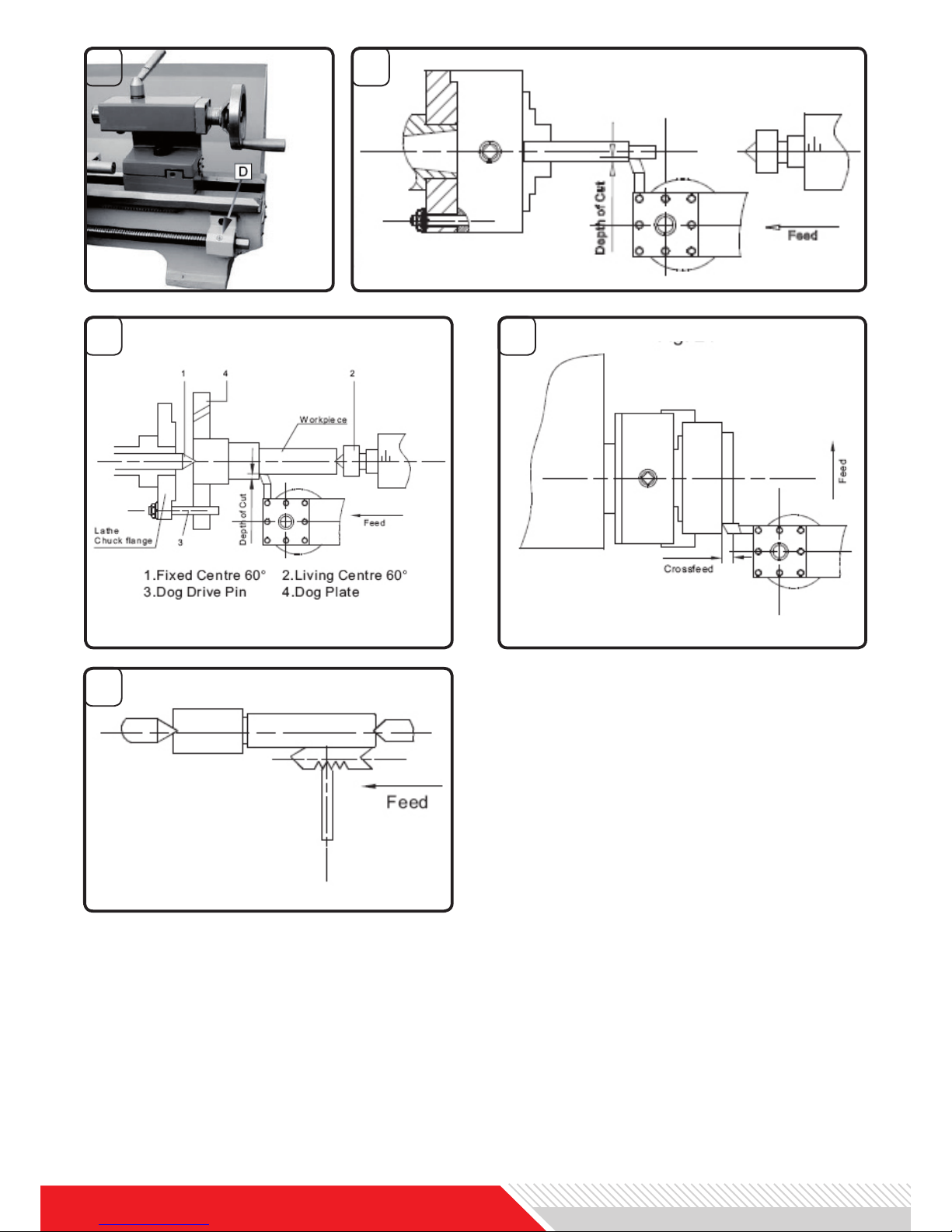
See gure 10, number D. The machine
can be switched on and off with the ON/
OFF button. Depress to stop all machine
functions. To restart, lift the cover and
press the green ON button.
See gure 10, number E. After the machine is switched on, turn the spindle direction switch E to the position „F“ for
counter clockwise rotation or to position
„R“ for clockwise spindle rotation. „0“ is
the OFF position and the spindle remains
idle.
See gure 10, number F. Turn the control knob clockwiese to increase and anti
clockwise to reduce the spindle speed.
The speed range depends from the drive
belt position.
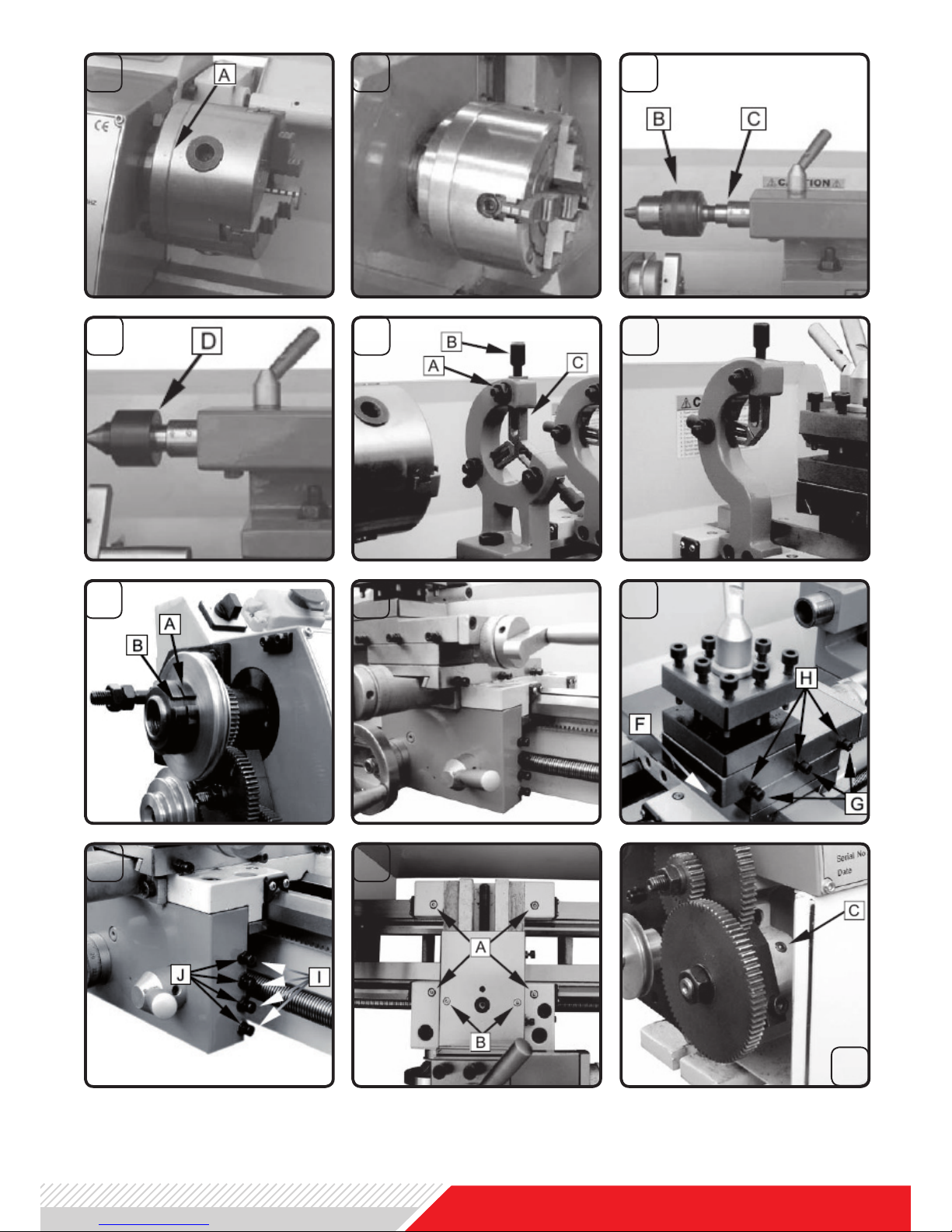
CARRIAGE - FIG. 5
HEADSTOCK - FIG. 4
APRON - FIG. 6
LEADSCREW - FIG. 8
TAILSTOCK - FIG. 9
EMERGENCY BUTTON ON/OFF
SPINDLE DIRECTION SWITCH
VARIABLE SPEED CONTROL KNOB
ENGLISH

CARRIAGE LOCK - Fig. 11
Turn the hex socket cap screw A clockwise and tighten it to lock. Turn it counterclockwise to loosen and unlock.
CAUTION: The carriage lock screw must
be unlocked before engaging into automatic feeds! Otherwise machine damage
might occur.
See Figure 12, number B.
Rotate the handwheel clockwise to move
the apron assembly towards the tailstock
(right).
Rotate the handwheel counter-clockwise
to move the apron assembly towards the
headstock (left).
See Figure 12, number C.
Clockwise rotation moves the cross slide
towards the rear of the machine.
See Figure 12, number D.
Move the lever down to engage. Move
the lever up to disengage.
See Figure 12, number E.
Rotate the lever to move the compound
rest.
See Figure 12, number F.
Rotate counter-clockwise to loosen and
clockwise to tighten. Rotate the tool post
when the lever is unlocked.
See Figure 13, number G.
Turn hex nut clockwise to lock and counter-clockwise to unlock.
See Figure 13, number H.
Rotate the lever clockwise to lock the
spindle and counter-clockwise to unlock.
LONGITUDINAL TRAVERSE HANDWHEEL
CROSS TRAVERSE LEVER
HALF NUT ENGAGE LEVER
COMPOUND REST TRAVERSE LEVER
TOOL POST CLAMPING LEVER
TAILSTOCK CLAMPING SCREW
TAILSTOCK QUILL CLAMPING LEVER
See Figure 13, number I
Rotate clockwise to advance the quill.
Rotate counter-clockwise to retract the
quill.
See Figure 13, number J
Three set screws loacted on the tailstock
base are used to off-set the tailstock for
cutting tapers. Loosen lock screw on tailstock end. Loosen one side set screw while tightening the other until the amount
of off-set is indicated on scale. Tighten
lock screw.
TAILSTOCK QUILL TRAVERSE HANDWHEEL
TAILSTOCK OFF-SET ADJUSTMENT
ENGLISH
 Loading...