

Page 1
DE Original Bet riebsanleitun g Metalldrehm aschin e
EN User Ma n ual
Metal turning lathe
ED 7 5 0 FDQ
Met a lldrehm a schine
Met a l t urning lathe
Bedienu ngsanleitung und Sicherheit shinweise lesen und beacht en!
Read the operation m anual carefully before fir st use!
Ausgabe/Edition: 2012 – Revision 02 – DE/EN
Tech nische Änderungen sowie
Druck- u nd Satzfehler vorbehalt en!
Tech nical data subj ect to
changes, err ors excepted!
Page 2

I NHALT / I NDEX
1 I NHALT / I NDEX
2 SICHERHEITSZEICHEN/SAFETYSIGNS....................................................................................................................5
3 VORWORT.............................................................................................................................................................6
4 TECHNIK................................................................................................................................................................7
4.1 TECHNISCHEDATEN.......................................................................................................................................................9
5 SICHERHEIT.........................................................................................................................................................10
5.1 BESTIMMUNGSGEMÄßEVERWENDUNG............................................................................................................................10
5.2 ARBEITSBEDINGUNGEN.................................................................................................................................................10
5.3 UNZULÄSSIGEVERWENDUNG.........................................................................................................................................10
5.4 GENERELLESICHERHEITSHINWEISE..................................................................................................................................11
5.5 ZUSÄTZLICHESICHERHEITSHINWEISEZURED750FDQ.......................................................................................................12
5.6 RESTRISIKEN...............................................................................................................................................................12
6 HAUPTFUNKTIONEN............................................................................................................................................13
6.1 SPINDELSTOCK.............................................................................................................................................................13
6.2 QUADRANT................................................................................................................................................................13
6.3 VORSCHUBKASTEN.......................................................................................................................................................13
6.4 HAUPTSCHLITTEN.........................................................................................................................................................13
6.4.1 Hauptschlittenkasten......................................................................................................................................13
6.4.2 Hauptschlittenplatine.....................................................................................................................................13
6.5 GEWINDEUHR.............................................................................................................................................................14
6.6 REITSTOCK..................................................................................................................................................................14
6.7 LÜNETTE....................................................................................................................................................................14
7 INBETRIEBNAHME...............................................................................................................................................15
7.1 TRANSPORT................................................................................................................................................................15
7.2 AUSPACKEN................................................................................................................................................................15
7.3 MONTAGEDERMASCHINEAUFDASUNTERGESTELL...........................................................................................................15
7.4 ELEKTRISCHERANSCHLUSS.............................................................................................................................................15
8 BEDIENUNG........................................................................................................................................................17
8.1 FUTTERWECHSEL..........................................................................................................................................................17
8.2 WERKZEUGEINSPANNUNG.............................................................................................................................................17
8.3 WECHSELDERGESCHWINDIGKEITSSTUFE..........................................................................................................................17
8.4 MANUELLESDREHEN....................................................................................................................................................18
8.5 LÄNGSDREHENMITVORSCHUB.......................................................................................................................................18
8.6 WECHSELRÄDERUMBAU................................................................................................................................................18
8.7 RUNDDREHEN(BILD8).................................................................................................................................................19
8.8 PLANDREHEN(BILD9)..................................................................................................................................................19
9 WARTUNG..........................................................................................................................................................20
10 PREFACE..........................................................................................................................................................21
11 TECHNICS........................................................................................................................................................22
11.1 TECHNICALDATA.........................................................................................................................................................24
12 SAFETYGUIDELINES.........................................................................................................................................25
12.1 PROPERUSAGE............................................................................................................................................................25
12.2 INCORRECTUSAGE.......................................................................................................................................................25
12.3 SAFETYINSTRUCTIONS..................................................................................................................................................25
12.4 SAFETYINSTRUCTIONSFORTHEED750FDQ.....................................................................................................................28
13 DESCRIPTIONOFTHEMAINUNITS...................................................................................................................29
HOLZMANN Maschinen Austria www.holzmann-maschinen.at
Metalldrehmaschine / metal turning lathe ED 750 FDQ
Se it e 2
Page 3

I NHALT / I NDEX
13.1 HEADSTOCK...............................................................................................................................................................29
13.2 QUADRANT................................................................................................................................................................29
13.3 FEEDBOX...................................................................................................................................................................29
13.4 FEEDDIRECTIONLEVER..................................................................................................................................................29
13.5 CARRIAGEGROUPANDITSMECHANISMS..........................................................................................................................29
13.5.1 Carriagebox....................................................................................................................................................29
13.5.2 Carriageboard................................................................................................................................................30
13.6 THREADINDICATOR......................................................................................................................................................30
13.7 TAILSTOCK.................................................................................................................................................................30
13.8 RESTS........................................................................................................................................................................30
14 INSTALLATION.................................................................................................................................................31
14.1 TRANSPORTATION........................................................................................................................................................31
14.2 UNPACKING................................................................................................................................................................31
14.3 HANDLING..................................................................................................................................................................31
14.4 PREPARATION.............................................................................................................................................................31
14.5 CONNECTIONTOTHEELECTRONICALSUPPLYSOURCE..........................................................................................................31
15 OPERATIONINSTRUCTIONS.............................................................................................................................32
15.1 REPLACEMENTOFCHUCK..............................................................................................................................................32
15.2 TOOLSET‐UP..............................................................................................................................................................32
15.3 CHANGESPEED............................................................................................................................................................32
15.4 MANUALTURNING.......................................................................................................................................................33
15.5 LONGITUDINALTURNINGWITHAUTO‐FEED.......................................................................................................................33
15.6 CHANGEGEARSREPLACEMENT.......................................................................................................................................33
15.7 STRAIGHTTURNING(FIG.10)..........................................................................................................................................34
15.8 FACINGANDRECESSES(FIG.11)......................................................................................................................................34
15.9 TURNINGBETWEENCENTERS(FIG.12).............................................................................................................................34
15.10 TAPERTURNINGUSINGTAILSTOCKOFF‐SET...................................................................................................................34
15.11 TAPERTURNINGBYSETTINGTHETOPSLIDE....................................................................................................................35
15.12 THREADCUTTING.....................................................................................................................................................35
15.12.1 Example:Malethread.................................................................................................................................35
16 ACCESSORIES...................................................................................................................................................36
16.1 THREEJAWUNIVERSALCHUCK...............................................................................................................................36
16.2 FOURJAWINDEPENDENTCHUCK...........................................................................................................................36
16.3 DRILLCHUCK(OPTIONAL)..........................................................................................................................................36
16.4 MORSETAPERARBOR(OPTIONAL)............................................................................................................................36
16.5 LIVECENTER(OPTIONAL)...........................................................................................................................................36
16.6 STEADYREST...........................................................................................................................................................37
16.7 SETTINGTHESTEADYREST......................................................................................................................................37
16.8 FOLLOWREST..........................................................................................................................................................37
17 MECHANISM’SADJUSTMENT...........................................................................................................................38
17.1 MAINSPINDLEBEARINGS........................................................................................................................................38
17.2 ADJUSTMENTOFCROSSSLIDE................................................................................................................................38
17.3 ADJUSTMENTOFTOPSLIDE....................................................................................................................................38
17.4 ADJUSTMENTOFHALFNUTGUIDE.........................................................................................................................38
18 LUBRICATION..................................................................................................................................................39
18.1 HEADSTOCK............................................................................................................................................................39
18.2 CHANGEGEAR.........................................................................................................................................................39
18.3 CARRIAGE................................................................................................................................................................39
18.4 CROSSSLIDE............................................................................................................................................................39
18.5 APRON....................................................................................................................................................................39
18.6 LEADSCREW............................................................................................................................................................40
18.7 TAILSTOCK...............................................................................................................................................................40
HOLZMANN Maschinen Austria www.holzmann-maschinen.at
Se it e 3
Metalldrehmaschine / metal turning lathe ED 750 FDQ
Page 4

I NHALT / I NDEX
19 MACHINECAREANDMAITENANCE..................................................................................................................41
20 TROUBLESHOOTING........................................................................................................................................42
21 SCHALTPLAN/CIRCUITDIAGRAM....................................................................................................................43
22 ERSATZTEILE/SPAREPARTS............................................................................................................................44
22.1 ERSATZTEILBESTELLUNG................................................................................................................................................71
22.2 SPAREPARTORDER......................................................................................................................................................71
23 KONFORMITÄTSERKLÄRUNG/CERTIFICATEOFCONFORMITY...........................................................................72
24 GARANTIEERKLÄRUNG....................................................................................................................................73
25 GUARANTEETERMS.........................................................................................................................................74
HOLZMANN Maschinen Austria www.holzmann-maschinen.at
Se it e 4
Metalldrehmaschine / metal turning lathe ED 750 FDQ
Page 5

SI CH ERHEI TSZEI CHEN / SAFETY SI GN S
2 SI CHERH EI TSZEI CH EN / SAFETY SI GNS
SI CHERHEITSZEICHEN
DE
BEDEUTUNG DER SYMBOLE
EN
SAFETY SIGNS
DEFINI TI ON OF SYMBOLS
DE W ARNUN G! Beachten Sie die Sicherheitssymbole! Die Nichtbeachtung
der Vorschriften und Hinweise zum Einsatz des Erdbohrers kan n zu schweren
Personenschäden und tödliche Gefahren m it sich bringen.
EN ATTEN TI ON! I gnoring the safet y signs and warnings applied on the m a-
chine as well as ignoring t he secur ity and operating instruct ions can cause
ser ious injuries and even lead t o death.
DE AN LEI TUNG LESEN! Lesen Sie die Betriebs- und War t ungsanleitung
I hrer Maschine aufmer ksam durch und m achen Sie sich m it den Bedienele-
EN READ THE MANUAL! Read the user and m aintenance m anual carefully
men t en der Maschine gut vertraut um die Maschin e ordnungsgemäß zu bedienen und so Schäden an Mensch und Maschine vorzubeugen.
and get familiar wit h the controls n order t o use t he machine correctly and
to av oid inj uries and machine defect s.
DE SCH UTZAUSRÜSTUNG! Das Tragen von Gehörschutz, Schutzbrille
sowie Sicherheitsschuhen ist Pflicht.
EN PROTECTI VE CLOTHI NG! The operat or is obligated to wear proper
ear protection, safety goggles and safety shoes
DE CE- KONFORM - Dieses Produkt ent spricht den EG-Richtlinien.
EN EC- CONFORM - This product com plies with t he EC-directiv es.
HOLZMANN Maschinen Austria www.holzmann-maschinen.at
Metalldrehmaschine / metal turning lathe ED 750 FDQ
Se it e 5
Page 6

VORW ORT
3 VORW ORT
Se hr geehrt er Kunde!
Diese Bedienungsanleitung enthält Informationen und wichtige Hinweise zur Inbetriebnahme und
Handhabung der Metalldrehmaschine ED 750FDQ.
Die Bedienungsanleitung ist Bestandteil der Maschine und darf nicht entfernt werden. Bewahren
Sie sie für spätere Zwecke auf und legen Sie diese Anleitung der Maschine bei, wenn sie an Dritte
weitergegeben wird!
Bitte b e ach t e n Sie die Sicherheit sh inw eise !
Lesen Sie vor Inbetriebnahme diese Anleitung aufmerksam durch. Der sachgemäße Umgang wird Ihnen dadurch erleichtert, Missverständnissen und etwaigen Schäden wird
vorgebeugt.
Halten Sie sich an die Warn- und Sicherheitshinweise. Missachtung kann zu ernsten Verletzungen führen.
Durch die ständ ige W eit erentw icklung unserer Produ k t e könn e n Abbildu n gen u nd I n halt e abw e ichen. Sollt en Sie Fe hler fest stellen, inform ieren Sie un s bitte per E- Mail oder
m it de m Prod uktinform a t ionsform ular.
Technische Änderun gen un d I rrtümer vo rbehalt en!
Urheberrecht
© 2012
Diese Dokumentation ist urheberrechtlich geschützt. Die dadurch verfassungsmäßigen Rechte
bleiben vorbehalten! Insbesondere der Nachdruck, die Übersetzung und die Entnahme von Fotos
und Abbildungen werden gerichtlich verfolgt – Gerichtsstand ist Rohrbach!
Kundendienstadressen
HOLZM ANN MASCH I N EN Gm bH
A-4170 Haslach, Marktplatz 4
Tel 0043 7289 71562 – 0
Fax 0043 7289 71562 – 4
[email protected]
HOLZMANN Maschinen Austria www.holzmann-maschinen.at
Se it e 6
Metalldrehmaschine / metal turning lathe ED 750 FDQ
Page 7
4 TECHN I K
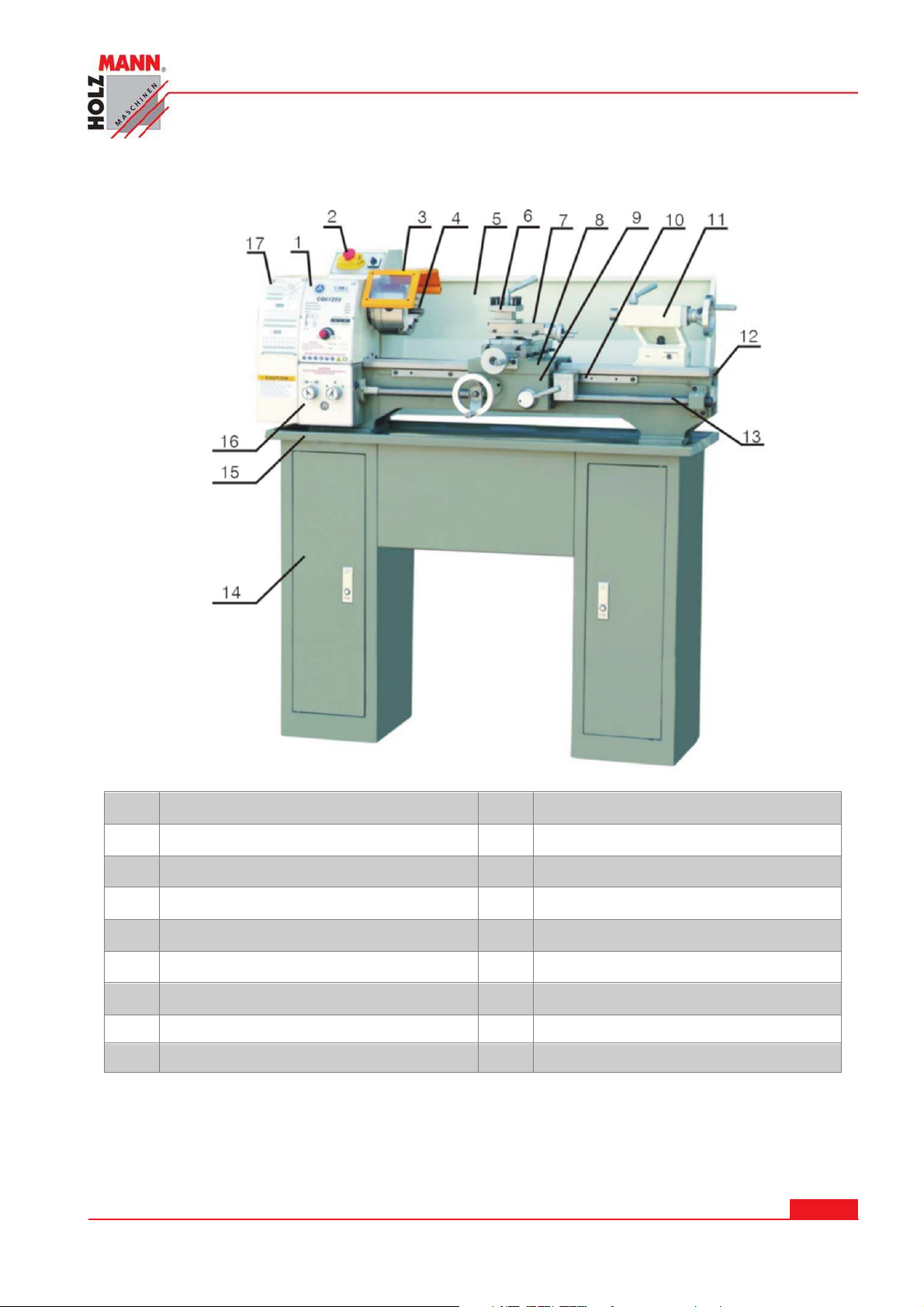
TECHNI K
1
2
3
4
5
6
7
Sicherheitsschalter EIN/AUS 11 Reitstock
Spindelstock 10 Gewindeuhr
Futterschutz 12 Maschinenbett
3-Backenfutter 13 Gewindespindel
Spritzschutz 14 Untergestell
Werkzeugaufnahme 15 Spänewanne
Oberschlitten 16 Vorschubkasten
8 Planschlitten 17 Getriebeabdeckung
9 Werkzeugschlitten
HOLZMANN Maschinen Austria www.holzmann-maschinen.at
Metalldrehmaschine / metal turning lathe ED 750 FDQ
Se it e 7
Page 8
TECHNI K
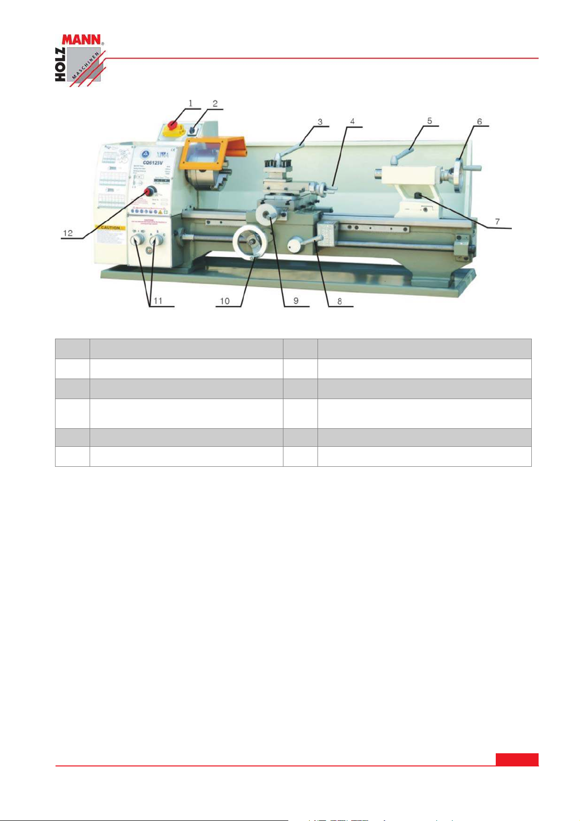
Sicherheitsschalter EIN/AUS 7 Schraube zur Reitstockfixierung
1
Links- Rechtslauf Wahlschalter 8 Wahlhebel für automatischen Vorschub
2
Werkzeugfixierhebel 9 Zustellrad für Querschlitten
3
Zustellrad für Planschlittenfeinzustel-
4
lung
10 Handrad für Längsschlitten
5 Pinolenfixierhebel 11 Einstellräder für Gewindesteigung
Pinolenhandrad am Reitstock 12 Einstellrad für Drehzahl
6
HOLZMANN Maschinen Austria www.holzmann-maschinen.at
Se it e 8
Metalldrehmaschine / metal turning lathe ED 750 FDQ
Page 9
4 .1 Technische D aten
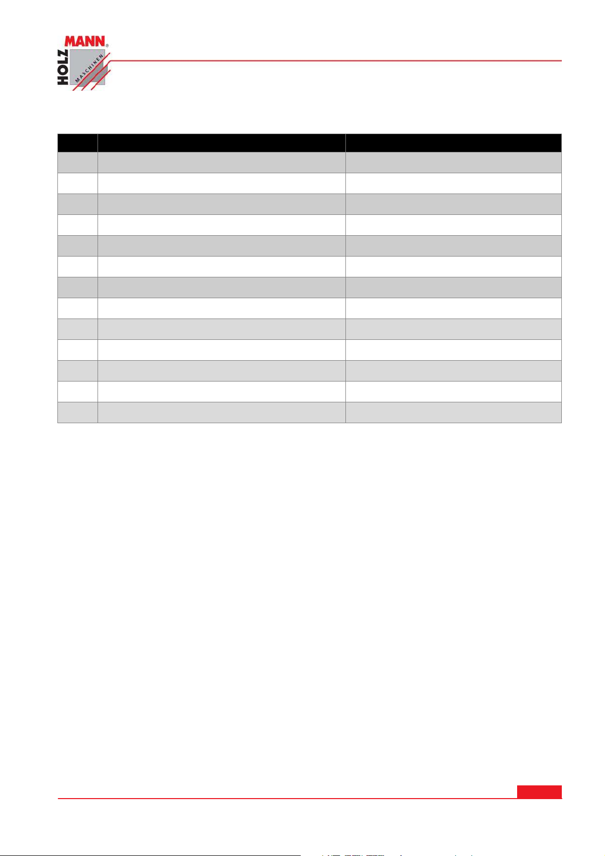
Nr. Sp ezifikat ion Pa ram eter
Max. Werkstücklänge 750mm
1
Max Drehdurchmesser 250mm
2
Drehdurchmesser über dem Querschlitten 150mm
3
Bettbreite 135mm
4
Spindelstockaufnahmekonus MK3
5
Spindelbohrung 21mm
6
Geschwindigkeitsstufen 2 steps
7
Spindeldrehzahl variable (2 Stufen) 0-2500rpm
8
Vorschubbereich 0.07-0.20mm/rew
9
TECHNI K
Bereich: englisches Gewinde 8-56.T.P.I
10
Bereich: metrisches Gewinde 0.4-3.5mm
11
Aufnahmekonus Reitstock MK2
12
Motor 750W (100%), 1,4PS (S6), 230V
13
HOLZMANN Maschinen Austria www.holzmann-maschinen.at
Se it e 9
Metalldrehmaschine / metal turning lathe ED 750 FDQ
Page 10

SI CH ERHEI T
5 SI CHERH EI T
5 .1 Be stim mu n gsgem äße Verw endung
Die Maschine nur in technisch einwandfreiem Zustand sowie bestimmungsgemäß, sicherheits- und
gefahrenbewusst benutzen! Störungen, welche die Sicherheit beeinträchtigen können, umgehend
beseitigen lassen!
Es ist generell untersagt, sicherheitstechnische Ausrüstungen der Maschine zu ändern oder unwirksam zu machen!
5 .2 Ar beit sbedingungen
Die Maschine ist für die Arbeit unter folgenden Bedingungen bestimmt:
Relative Luftfeuchtigkeit
Betriebstemperatur von +5°С bis +40°С
max. Höhe über dem Meeresspiegel 1800m
min. Beleuchtung 500 Lux
Die Maschine ist nicht für den Betrieb im Freien bestimmt.
Die Maschine ist nicht für den Betrieb in einer Umgebung bestimmt, die elektromagnetisch be-
lastet ist ("Elektrosmog").
Die Maschine ist nicht für den Betrieb in einer Arbeitsumgebung mit Gasen, Dämpfen u.a. be-
stimmt, welche die Isolierung der elektronischen Komponenten angreifen, korrodieren oder
zerstören könnten.
Die Maschine ist nicht für den Betrieb unter explosionsgefährlichen Bedingungen bestimmt.
Die Maschine ist nicht für den Betrieb in einer Arbeitsumgebung bestimmt, in der regelmäßig
Vibrationen auftreten, da diese die Leistungsfähigkeit, Arbeitsgenauigkeit und Lebensdauer
der Maschine vermindern.
Die Bearbeitung von entzündbaren und explosiven Materialien ist verboten (z.B. reines Aluminium, Magnesium etc.).
Bei 40°C max. 50%
Bei 20°C max. 90%
5 .3 Unzulässige Verw endung
Der Betrieb der Maschine unter Bedingungen außerhalb der in dieser Anleitung angegebe-
nen Grenzen ist nicht zulässig.
Der Betrieb der Maschine ohne die vorgesehenen Schutzvorrichtungen ist unzulässig;
die Demontage oder das Ausschalten der Schutzvorrichtungen ist untersagt.
Etwaige Änderungen in der Konstruktion der Maschine sind verboten.
Eine Überlastung der Maschine ist nicht zulässig.
Der Betrieb der Maschine ohne Kühlflüssigkeit ist verboten.
Der Betrieb der Maschine mit unzureichender Ölung/Schmierung ist verboten.
Der Betrieb der Maschine auf eine Art und Weise bzw. zu Zwecken, die den Anweisungen
dieser Bedienungsanleitung nicht zu 100% entspricht, ist untersagt.
Für eine a n dere oder darübe r hinausgehende Benutzung und da r a u s resultie rende
Sa chschäden ode r Verletzunge n übe rnimm t HOLZMAN N - MASCH I N EN k eine Verantw or t u ng oder Gar a n t iele ist ung.
HOLZMANN Maschinen Austria www.holzmann-maschinen.at
Metalldrehmaschine / metal turning lathe ED 750 FDQ
Se it e 1 0
Page 11
SI CH ERHEI T
5 .4 Gen e relle Sich erheitshinw eise
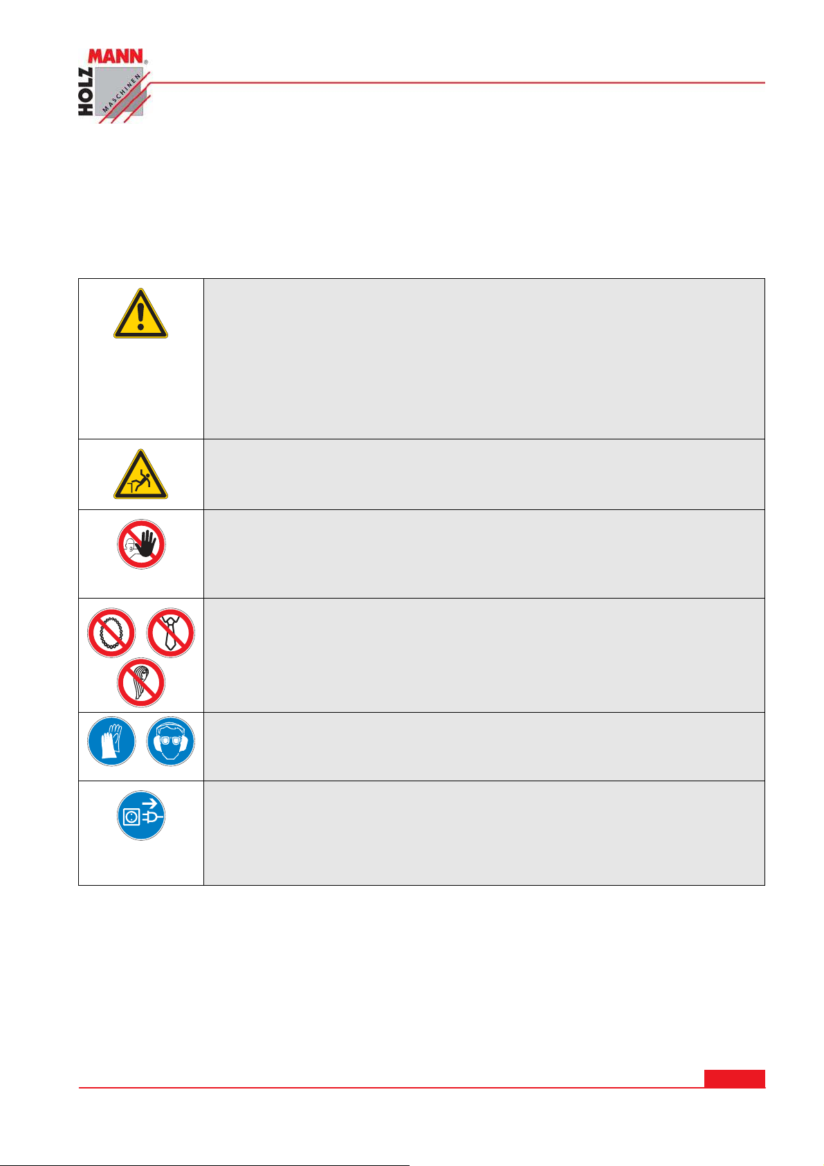
Warnschilder und/oder Aufkleber an der Maschine, die unleserlich sind oder entfernt wurden, sind
umgehend zu erneuern!
Zur Vermeidung von Fehlfunktionen, Schäden und gesundheitlichen Beeinträchtigungen sind folgende Hinweise UNBEDINGT zu beachten:
Am Ge rät be finde n sich nur w enige von I hnen zu w artende n Kom ponent en. Es ist n icht
not w endig, die Masch ine zu d em on t ieren. Reparaturen nur durch d e n Fachm a n n du r chführ e n la ssen!
Zube hör: Verw ende n Sie nur v on H OLZMAN N e m pf ohle nes Zub ehör!
W end en Sie sich b e i Frag en un d Problem e n an unse re Kunden betreuung .
Ar beitsbereich und Boden rund um die M a schin e sauber und frei von
Öl, Fett, Kü h lflüssigkeit und Materia lrest en ha lten!
Für eine a u sreich ende Be leuchtung im Arbeit sbe reich der Ma schin e
sorgen!
Die Masch ine nicht im Fr eien verw e n den!
Be i M ü dig k e it, Unkon zentrie r t h eit bzw . unter Einfluss von Medik a -
m e n t e n, Alk ohol oder D r ogen ist da s Arb eiten an d e r Maschine
verboten!
Das Klettern auf die Maschine ist verboten!
Schw ere Verle t z u ngen durch H e r u nterfallen oder Kippe n der
Masch ine sind m öglich!
Die Masch ine darf nur v om ein geschu lten Fachpe r sonal bedient w erden.
Unbe fugte, insbeson dere Kinder, und nicht e inge schult e Pe r sonen
sind von der lauf enden Maschine fern z u halten!
W enn Sie an de r Maschine arbeit e n, t r a gen Sie kein en lockeren
Schm uck, w eite Kle idung, Kraw a t ten ode r lan ges, offenes Haar .
Lose Objekte können sich in rot ierende n und bew ege n den Objekten
verfa n gen u nd z u sch w ere n Verletzunge n fü h r en!
Be i Arbe iten a n der Maschine geeign ete Schutzausrüst ung
( Schutzha n dschuh e , Schutzbrille, Gehörschu t z , Schutzm a ske…) t r a gen!
Vor W a r t u ngsarbeit e n od er Einst ellarbe iten ist die M a schin e von de r
Spannung sve r sorgung zu t r ennen! Vor de m Tren n en de r Spannu n gsversorg ung den H a u ptscha lter a u sschalten ( OFF) .
Verw e nden Sie da s N e t z kabel nie zum Transport oder zur
Manipulation der M a schin e!
HOLZMANN Maschinen Austria www.holzmann-maschinen.at
Metalldrehmaschine / metal turning lathe ED 750 FDQ
Se it e 1 1
Page 12

SI CH ERHEI T
5 .5 Zusät zlich e Sicherheitshin w eise zur ED 7 5 0 FDQ
Alle am Gerät arbeitenden Personen müssen die Sicherheitshinweise kennen und über die Möglichkeiten zur Vermeidung von Unfällen und Verletzungen Bescheid wissen.
Einige der wichtigsten Vorsorgemaßnahmen bei der Bedienung der Maschine sind:
1. Die richtige Arbeitskleidung ist sehr wichtig, entfernen Sie Schmuck und Uhren und krempeln
Sie die Ärmel hoch.
2. Schalten Sie die Maschine immer aus, bevor Sie neue Einstellungen machen.
3. Ändern Sie die Spindelgeschwindigkeit erst, wenn die Drehbank komplett zum Stillstand
kommt.
4. Gehen Sie vorsichtig mit scharfen Messern und Bohrern um.
5. Entfernen Sie die Futterschlüssel und Kreuzschlüssel vor dem Arbeiten.
6. Tragen Sie immer Augenschutz.
7. Gehen Sie mit dem schweren Futter vorsichtig um und schützen Sie die Vorschubbahnen mit
einem Stück Holz wenn Sie das Futter installieren.
8. Benutzen Sie immer Zangen oder Bürsten um Späne zu entfernen, führen Sie das niemals
mit Ihren Händen durch.
9. Lehnen Sie sich niemals an die Drehbank an.
10. Lassen Sie kein Werkzeug auf der Führungsbahn liegen, beschaffen Sie sich dazu einen separaten Arbeitstisch.
11. Benützen Sie beide Hände um das Arbeitsstück abzuschleifen.
5 .6 Restr isike n
Auch bei Einhaltung aller Sicherheitsbestimmungen und bei bestimmungsgemäßer Verwendung
sind folgende Restrisiken zu beachten:
Verletzungsgefahr für die Hände/Finger durch den rotierenden Bohrkopf während dem Be-
trieb.
Haare und lose Kleidung etc. können vom rotierenden Bohrkopf erfasst und aufgewickelt
werden! Schwere Verletzungsgefahr! Sicherheitsbestimmungen bzgl. Arbeitskleidung unbedingt beachten.
Verletzungsgefahr durch Kontakt mit spannungsführenden Bauteilen.
Verletzungsgefahr durch Kippen der Maschine
Schnittgefahr durch nicht entgratete Bohrkanten
Verletzungsgefahr für das Auge durch herumfliegende Teile, auch mit Schutzbrille.
Gefahr durch Freisetzen von chemischen Partikeln im zu bearbeitenden Material, die
krebserregend oder sonst für die Gesundheit schädlich sind.
Diese Risiken können reduziert werden, wenn alle Sicherheitsbestimmungen angewendet werden,
die Maschine ordentlich gewartet und gepflegt wird und die Maschine bestimmungsgemäß und
von entsprechend geschultem Fachpersonal bedient wird. Trotz aller Sicherheitsvorrichtungen ist
und bleibt Ihr gesunder Hausverstand und Ihre entsprechende technische Eignung/Ausbildung zur
Bedienung einer Maschine wie der UWS 320 der wichtigste Sicherheitsfaktor.
HOLZMANN Maschinen Austria www.holzmann-maschinen.at
Se it e 1 2
Metalldrehmaschine / metal turning lathe ED 750 FDQ
Page 13
HAU PTFUN KTI ON EN
6 HAUPTFUNKTI ONEN
6 .1 Spindelstock
Der Spindelstock liegt an der linken Seite der Maschine. Kräftige und vorgespannte Lager führen
die Arbeitsspindel, welche als Hohlwelle ausgeführt ist. Über Riementrieb und Getriebe ist die Arbeitsspindel mit dem Motor gekoppelt.
6 .2 Quadrant
Der Quadrant ist dazu ausgerichtet, das Treibwerk vom Spindelstock zum Vorschubkasten durch
Wechselräder zu transportieren. Der Quadrant ist im geschlossenen Quadratenkasten montiert.
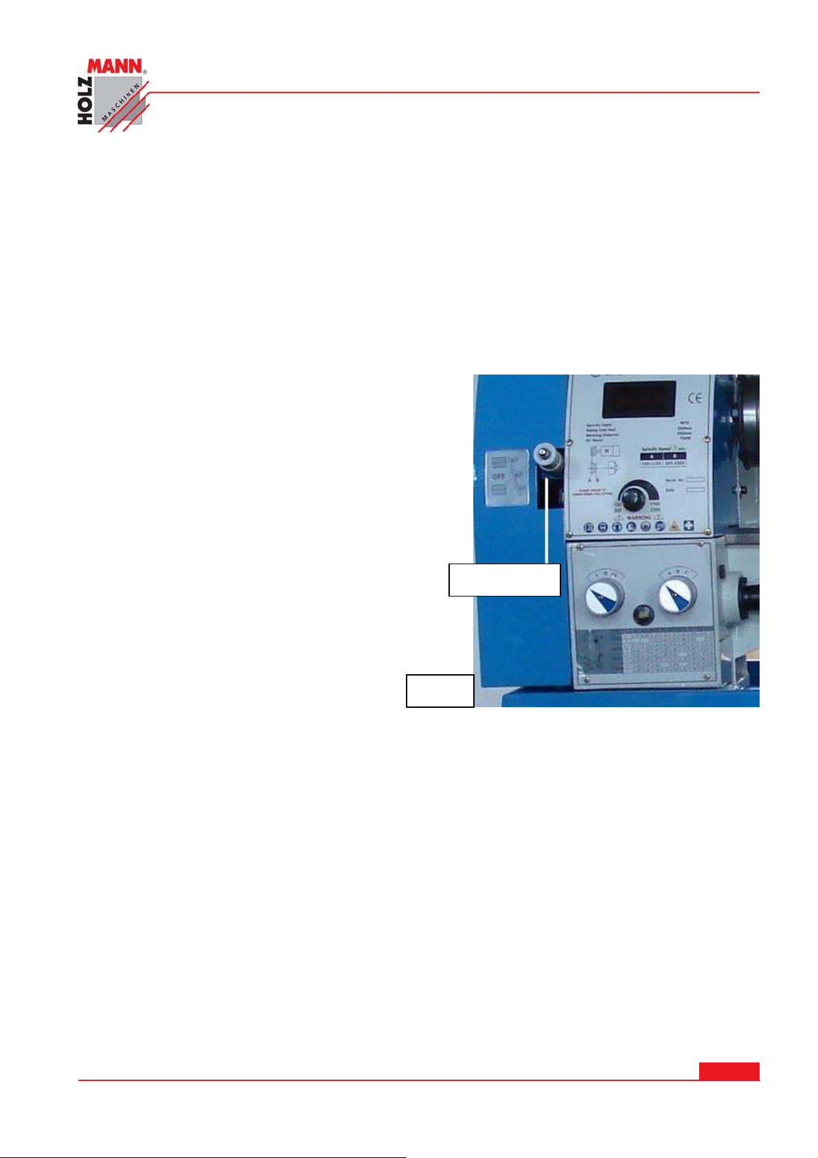
6 .3 Vorschubkast en
Der Vorschubkasten ist auf der Vorderseite der Maschine befestigt, gleich unter dem Spindelstock. Er
beinhaltet alle Mechanismen, die für die Einstellung
des Vorschubs oder Gewindegangs nötig sind.
Die Einstellung der Geschwindigkeit des Vorschubs,
oder des Gewindegangs werden mit Hilfe von Trommeln auf der Vorderseite des Vorschubkastens ermöglicht.
6 .4 Haupt schlitte n
Der Hauptschlitten besteht aus fünf Teilen: Hauptschlittenkasten, Hauptschlittenplatine, unterer
Schlitten, Querschlitten und Oberschlitten.
Auf dem Bett verfährt in Längsrichtung der als Kreuzsupport ausgeführte Hauptschlitten, auf dem
der Planschlitten quer zur Drehachse verfährt. Als Werkzeugträger befindet sich obenauf der
Oberschlitten, der einen Werkzeughalter trägt.
6 .4 .1 Haupt schlit t e nkast e n
Der Hauptschlittenkasten ist auf der Hauptschlittenplatine montiert. Er beinhaltet die Mechanismen für den Längs- und Quervorschub und den Mechanismus zum Eingreifen der Nuss in die
Spindel während dem Gewindeschneiden. Außerdem den Mechanismus für den Planvorschub.
Bild 1
Einstellhebel
6 .4 .2 Haupt schlit t e npla t ine
Der untere Schlitten fährt auf der Führungsschiene der Hauptschlittenplatine. Wenn kurze Zapfen
von Hand gedreht werden müssen, müssen Sie das Querstück um 90° vor den Unterschlitten in
beide Richtungen drehen und in der gewünschten Position durch Schrauben fixieren.
Der Oberschlitten, auf dem der 4-Positionen Werkzeughalter montiert ist, muss von Hand in die
Richtung des Querstückes geschoben werden.
HOLZMANN Maschinen Austria www.holzmann-maschinen.at
Metalldrehmaschine / metal turning lathe ED 750 FDQ
Se it e 1 3
Page 14
ACH TUNG:
Schalten Sie nicht gleichzeitig den Längsvorschub und
den Planvorschub zusammen. Dadurch kann das Getriebe zu Schaden kommen.
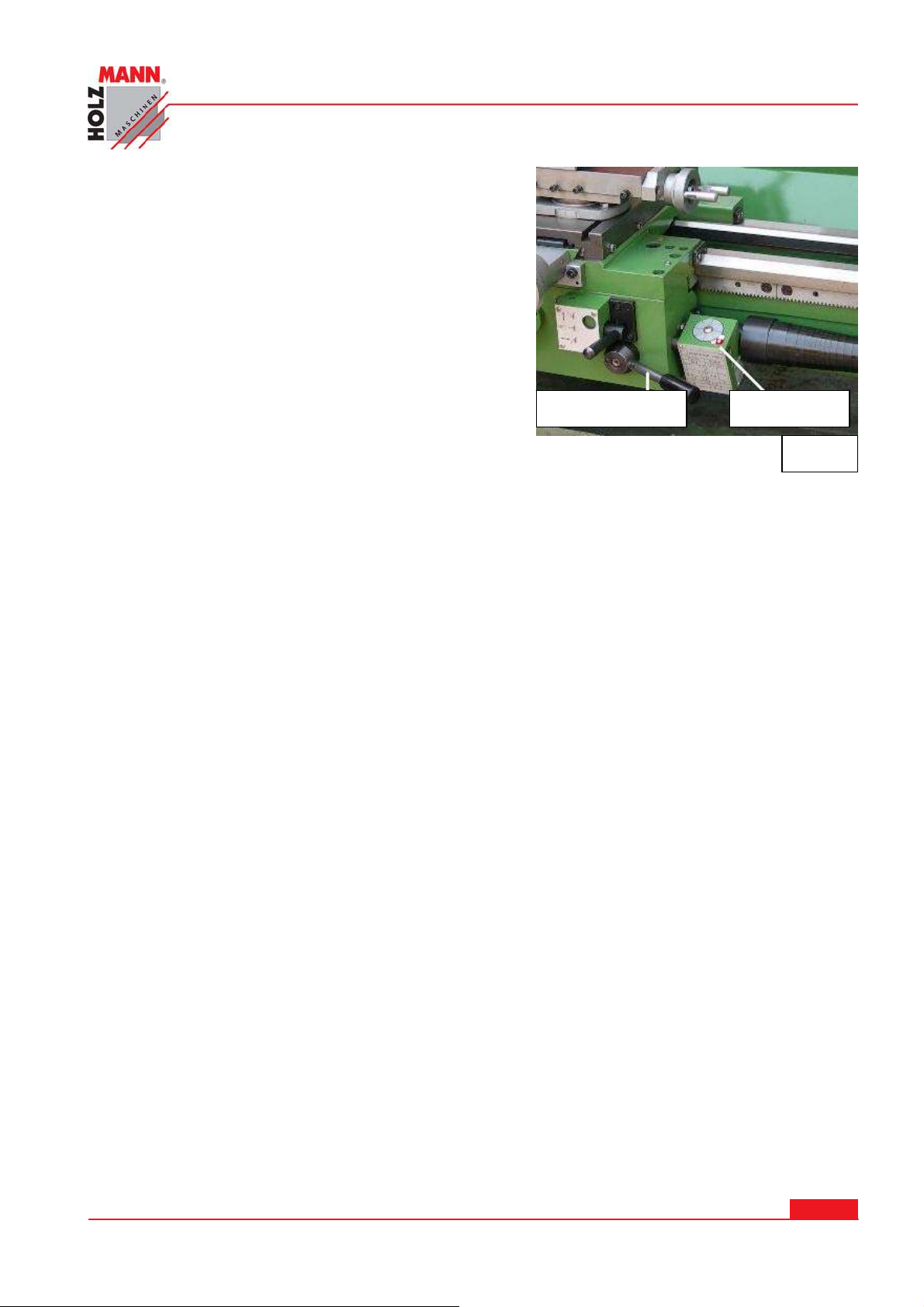
Vorschub- / Gew indehebe l – Mit diesem Hebel wird
die Schloßmutter auf der Leitspindel gesetzt und dadurch der eingestellte Vorschub in Einsatz gebracht.
HAU PTFUN KTI ON EN
Gewindeuhr Vorschubhebel
6 .5 Gew indeu h r
Bild 2
Sie ist rechts unten am Werkzeugschlitten montiert und dient als Hilfe beim Gewindeschneiden,
damit während des Gewindeschneidens der korrekte Gewindegang behalten wird.
6 .6 Reit stock
Der Reitstock dient zum Abstützen langer Drehteile mittels einer Zentrierspitze, die in die stirnseitig in das Werkstück eingebrachte Zentrierbohrung eingreift. Die Maschine verfügt über eine Pinole im Reitstock mit Morsekegelaufnahme MK2 für Bohrfutter oder große Bohrer, welche mit einem
Handrad parallel zum Bett herausgedreht werden kann zum Herstellen zentrischer Bohrungen.
6 .7 Lüne t te
Mit der Lünette können lange, dünne Drehteile an jeder beliebigen Stelle abgestützt werden. Sie
verhindert ein Schwingen und Durchbiegen des Werkstücks aufgrund des Eigengewichts und der
Bearbeitungskräfte.
.
HOLZMANN Maschinen Austria www.holzmann-maschinen.at
Se it e 1 4
Metalldrehmaschine / metal turning lathe ED 750 FDQ
Page 15
I NBETRI EBNAH M E
7 I NBETRI EBNAH ME
7 .1 Transport
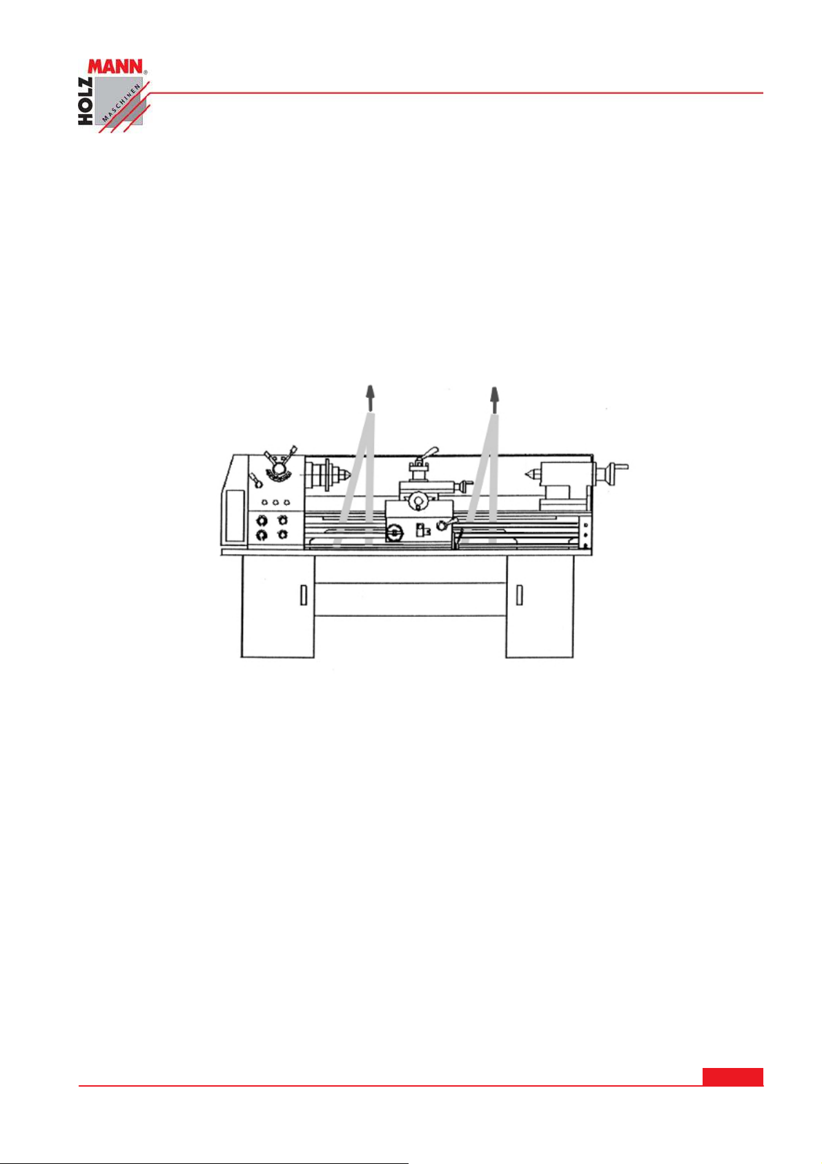
Zum Transport der Maschine bzw. zum Aufsetzten der Maschine auf den Unterbau bei der Inbetriebnahme, eignet sich am besten ein Hebegurt mit ausreichender Tragkraft. Legen Sie den Gurt
durch die Innenstege des Gussbettes und heben Sie die Maschine vorsichtig mit Hilfe eines Kranes bzw. einer anderen geeigneten Hebeeinrichtung.
Beachten Sie, dass sich die gewählten Hebeeinrichtungen (Kran, Stapler, Hebegurt etc.) in einwandfreiem Zustand befinden. Vergewissern Sie sich ebenfalls, dass der Aufstellort dem Gewicht
der Maschine standhält, speziell bei Aufstellung der Maschine oberhalb des Erdgeschoßes.
7 .2 Au spack en
Packen Sie die Maschine und das Untergestell aus den Verpackungen aus. Entfernen Sie das
Schutzpapier von den bearbeiteten Metallflächen und entfernen Sie gegebenenfalls Korrosionsstellen mit einem geeigneten Rostentfernungsmittel.
7 .3 Montage der Maschin e a uf das Unt ergest ell
Heben Sie nun die Maschine vorsichtig auf das Untergestell. Schrauben Sie nun die Maschine mit
den mitgelieferten Schrauben sachgemäß, auf dem Untergestell fest. Nur wenn die Maschine ordnungsgemäß befestigt wird, kann die mögliche Fertigungsgenauigkeit der Maschine eingehalten
werden.
7 .4 Elektr ischer An schluss
VORSI CHT: Der elektrische Anschluss darf ausschließlich durch eine qualifizierte Fachkraft
durchgeführt werden.
HOLZMANN Maschinen Austria www.holzmann-maschinen.at
Metalldrehmaschine / metal turning lathe ED 750 FDQ
Se it e 1 5
Page 16

I NBETRI EBNAH M E
Bei unsachgemäßem Anschluss der Phasen kann keine Garantieleistung in Anspruch genommen
werden.
Probieren Sie nach Anschluss der Maschine die beiden Drehrichtungen, mittels Anwahl des LinksRechtslaufes aus.
Prüfen Sie nun auch ob die Drehzahlregelung ordnungsgemäß funktionier.
ACH TEN SI E DARAUF, DASS BEI M EI N SCHALTEN DER MASCHI NE DER DREH ZAHLREG-
LER AUF 0 STEH T!
HOLZMANN Maschinen Austria www.holzmann-maschinen.at
Se it e 1 6
Metalldrehmaschine / metal turning lathe ED 750 FDQ
Page 17
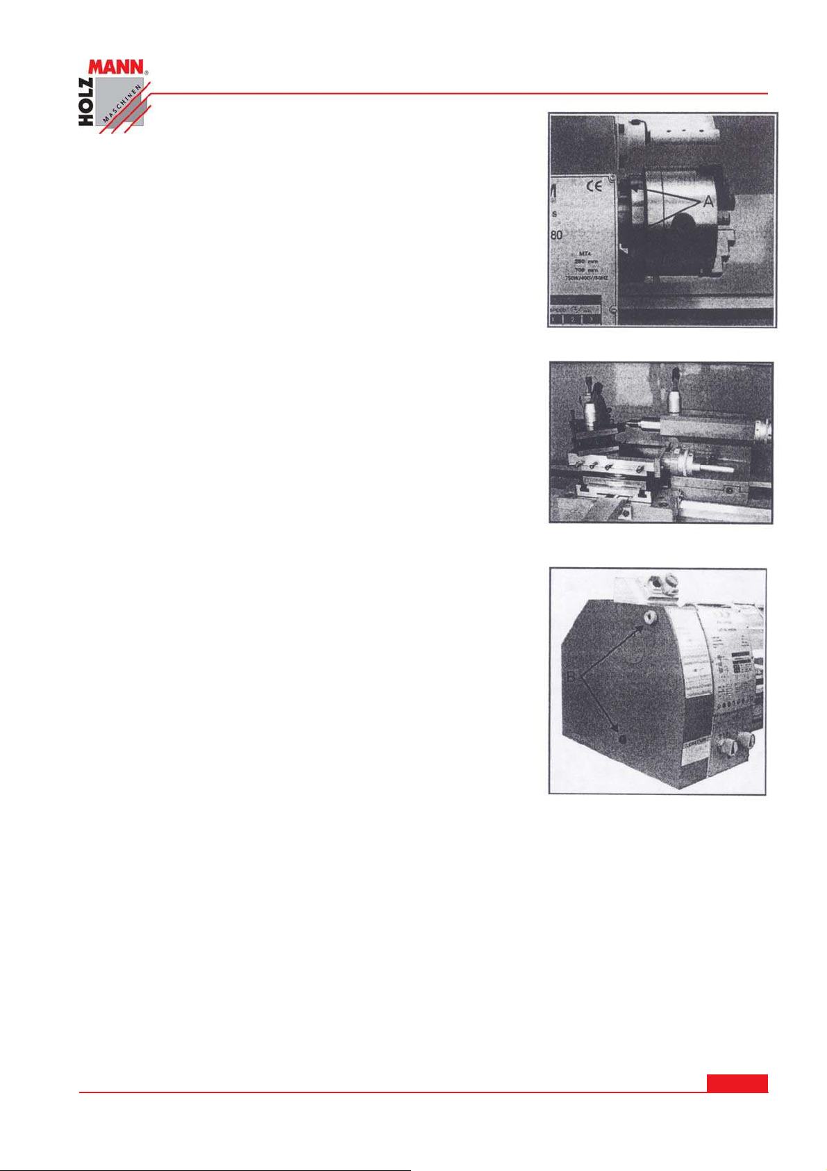
Bild 1
8 BED I ENUNG
8 .1 Fut terw echse l
Lösen sie die drei Schrauben (Bild 3) die am Umfang des Futters angebracht sind. Ziehen sie und das bestehende Futter
vorsichtig von der Spindel. Danach ein anderes Futter in umgekehrter Reihenfolge wieder montieren.
BED I EN U N G
Fig.3
8 .2 W erkze u geinspannung
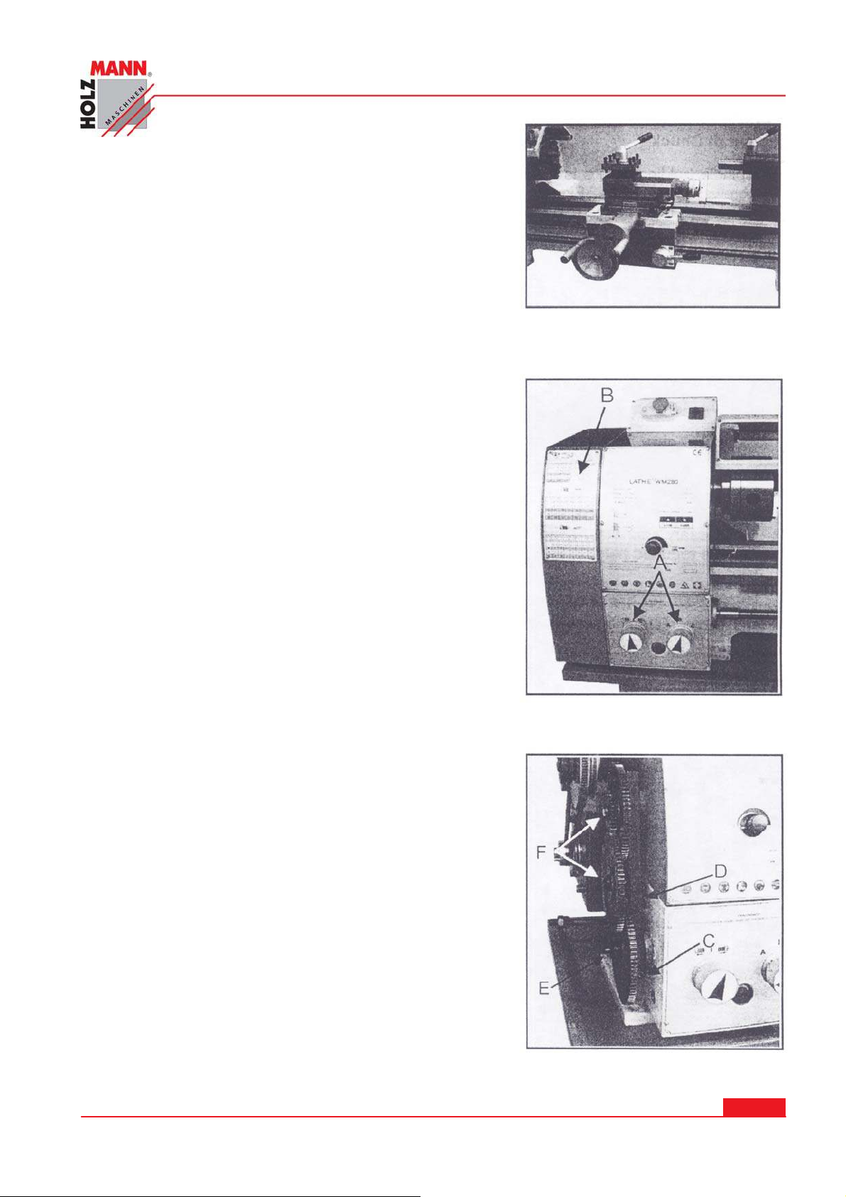
Fixieren Sie das gewünschte Werkzeug im Werkzeughalter (Bild
4). Es ist zu empfehlen, dass das Werkzeug so wenig weit wie
möglich weit aus dem Werkzeughalter ragt, um Schwingungen
am Werkzeug zu vermeiden.
Der Werkzeughalter kann auch, wenn von der Bearbeitung her
notwendig, winkelig gedreht werden indem der Fixierhebel
oben gelockert, der Werkzeughalter entsprechend gedreht und
dann wieder fixiert wird.
Bild 3
Bild 4
8 .3 W ech sel der Ge schw indigkeitsstufe
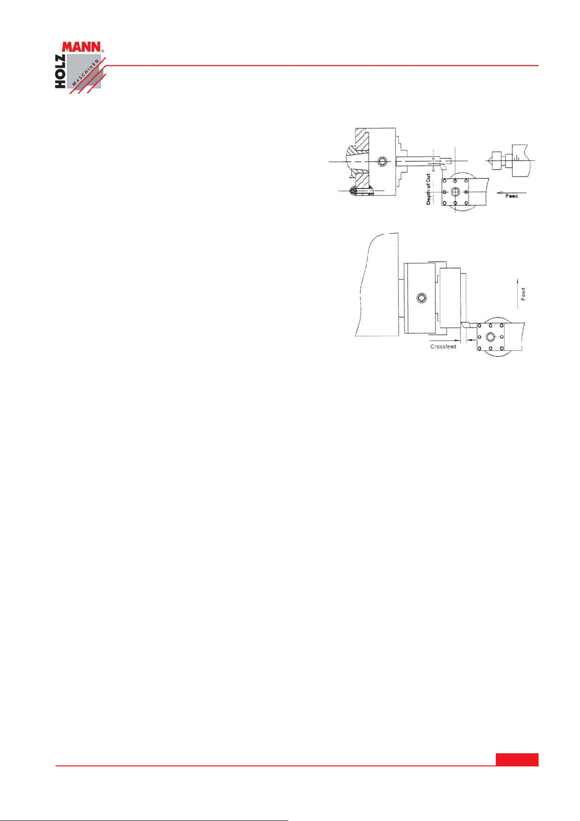
1. Öffnen sie die Getriebeabdeckung, indem sie die Schrauben “B” abnehmen, wie im Bild 5 ersichtlich.
2. Lockern sie die Schraube (C, Bild 5) um den V-Riemen zu
entspannen.
3. Legen Sie den Riemen in die “2te” Position des Riemenrad.
4. Spannen Sie den Riemen wieder in umgekehrter Reihenfolge wie in Punkt 2 beschrieben.
ACH TUNG:
Achten Sie darauf, dass der Riemen so gespannt ist, das er beim Lauf ruhig und formschlüssig in
den Riemenrädern läuft. Bei zu geringer Spannung kann der Riemen die Motorkraft nicht auf das
Getriebe übertragen. Bei zu hoher Spannung verschleißt der Riemen schneller als gewöhnlich.
Bild 5
HOLZMANN Maschinen Austria www.holzmann-maschinen.at
Se it e 1 7
Metalldrehmaschine / metal turning lathe ED 750 FDQ
Page 18
8 .4 m anuelle s Drehen
Der Werkzeugschlitten kann längs und quer durch die
Drehung der entsprechenden Handräder bewegt werden.
Die genauen Wege können über die, bei den Handrädern
angebrachten, Noniusskalen abgelesen werden
8 .5 Län gsdrehen m it Vorschub
BED I EN U N G
Bild 6
Suchen Sie aus dem Diagramm (B) die gewünschte Gewindesteigung und ermitteln sie die entsprechenden Hebelpositionen (A) ebenfalls aus der Tabelle.
Die Gewindesteigung kann nur im Stillstand der Maschine
eingestellt werden! Sollten sich die Positionen der Hebel
A nicht einrasten lassen drehen Sie die Hauptspindel (Backenfutter) etwas mit der Hand.
8 .6 W ech selräderum bau
1. Trennen Sie die Maschine von der Stromversorgung.
2. Öffnen sie die Abdeckung des Spindelstockes
3. Lockerns sie die Schraube (C, Bild 8).
4. Schwenken Sie das Element D, Bild 8) nach rechts
5. Schrauben sie den Bolzen (E, Bild 9) von der Spindel
um die Wechselräder abzunehmen.
6. Montieren sie das Räderpaar entsprechend der Tabelle (Fig.10) und fixieren sie diese.
7. Schwenken die das Element (D, Bild 8) nach links,
damit das Zahnrad wieder eingreift.
8. Fixieren sie das Element (D, Bild 8).
9. Montieren Sie die Abdeckung wieder und nehmen Sie
die Maschine wieder in Betrieb.
Fig. 6
Bild 7
HOLZMANN Maschinen Austria www.holzmann-maschinen.at
Bild 8
Se it e 1 8
Metalldrehmaschine / metal turning lathe ED 750 FDQ
Page 19
8 .7 Runddr ehen ( Bild 8 )
Für diese Funktion müssen die Vorschübe parallel
zur Rotationsachse des Werkstückes stehen. Der
Vorschub kann manuell durch Drehen des Handrades
auf dem Drehmaschinenschlitten oder dem Oberschlitten passieren, bzw. durch Aktivieren des automatischen Vorschubes. Der Quervorschub für die
Schnitttiefe wird durch den Querschlitten ausgeführt.
8 .8 Pla n d r ehen ( Bild 9 )
Im Plandrehungs-Betrieb befindet sich der Hauptschlitten senkrecht zur Rotationsachse des Werkstückes. Der Vorschub wird manuell mit Hilfe des Quervorschub-Handrades ausgeführt. Der Quervorschub
für die Schnitttiefe wird mittels Ober- oder Drehmaschinenschnitten ausgeführt.
BED I EN U N G
Bild 9
Bild 10
HOLZMANN Maschinen Austria www.holzmann-maschinen.at
Se it e 1 9
Metalldrehmaschine / metal turning lathe ED 750 FDQ
Page 20
W ARTUNG
A
9 W ARTUN G
ACH TUNG
Störungen oder Defekte, die die Sicherheit der Maschine beeinträchtigen können, umge-
Die vollständige und regelmäßige Reinigung der Maschine garantiert eine lange Lebens-
Prüfen Sie regelmäßig, ob die Warn- und Sicherheitshinweise an der Maschine vorhanden
Prüfen Sie vor jedem Betrieb den einwandfreien Zustand der Sicherheitseinrichtungen.
Bei Lagerung der Maschine darf diese nicht in einem feuchten Raum aufbewahrt werden
Kontrollieren Sie zumindest wöchentlich alle Schraubverbindungen auf festen Sitz.
Die Bese itigu ng v on D efekten erledigt I hr Fachhändler
Repa r a t u r t ä t igkeiten dürfen nur v on Fachpersonal durchgefü h r t w erde n
Um gewährleisten zu können, dass die Maschine Ihre vorgesehene Lebensdauer und Genauigkeit
hält, ist es zwingend notwendig den folgenden Schmierplan einzuhalten.
Kontrollieren Sie den Ölstand vor jeder Inbetriebnahme
des Spindelkastens (Schmieröltyp: FINA GLP oder ein vergleichbares),
des Vorschubgetriebes und (Schmieröltyp: GLP 68)
des Schlosskastens. (Schmieröltyp: GLP 68)
Wechseln Sie sämtliche Öle nach den ersten 150h Betriebsstunden oder spätestens nach einem
viertel Jahr. Danach müssen Sie das Öl nur noch jährlich wechseln. Die Füllstände müssen vor
jeder Inbetriebnahme durch Blick auf die Ölschaugläser kontrolliert und gegebenenfalls nachgefüllt werden. Entsorgen Sie das Öl ordnungsgemäß.
Beim Ölwechsel muss die Maschine ausgesteckt werden
Be i Reinigung un d I n st a n dhaltung be i a ngeschlosse ner M asch ine:
Sa ch schä d en und sch w ere Ve r letz unge n du rch u nbeab sichtig tes Ein scha lten der Ma-
sch ine m öglich!
Daher gilt:
Vor Wartungsarbeiten Maschine ausschalten und von der Spannungsversorgung trennen
hend beseitigen lassen.
dauer und stellt eine Sicherheitsvoraussetzung dar. Verwenden Sie ausschließlich milde
Reinigungsmittel, d.h. kein Benzin, Petroleum, Soda etc …
und in einwandfrei leserlichem Zustand sind.
und muss gegen den Einfluss von Witterungsbedingungen geschützt werden.
HOLZMANN Maschinen Austria www.holzmann-maschinen.at
A
Metalldrehmaschine / metal turning lathe ED 750 FDQ
Se it e 2 0
Page 21

PREFACE
1 0 PREFACE
Dear Custom er!
This manual contains Information and important instructions for the installation and correct use of
the metal turning lathe ED 750FDQ.
This manual is part of the machine and may not be stored separately from the machine. Save it
for later reference and if you let other persons use the machine, add this instruction to the machine.
Please read and follow the safet y instructions!
Before first use read this manual carefully. It eases the correct use of the machine and
prevents misunderstanding and damages of machine and the user’s health.
Due to constant advancements in product design, construction pictures and content may diverse
slightly. However, if you discover any errors, inform us please with the product feedback form.
Technical specifications are subject to changes!
Copyright
© 2012
This document is protected by international copyright law. Any unauthorized duplication, transla-
tion or use of text of this manual will be pursued by law.
Court of jurisdiction is A-4020 Linz, Austria!
Custom er Service Contact
HOLZM ANN MASCHI NEN Gm bH
Marktplatz 4
A-4170 Haslach
Tel 0043 7289 71562 – 0
Fax 0043 7289 71562 – 4
[email protected]
HOLZMANN Maschinen Austria www.holzmann-maschinen.at
Se it e 2 1
Metalldrehmaschine / metal turning lathe ED 750 FDQ
Page 22
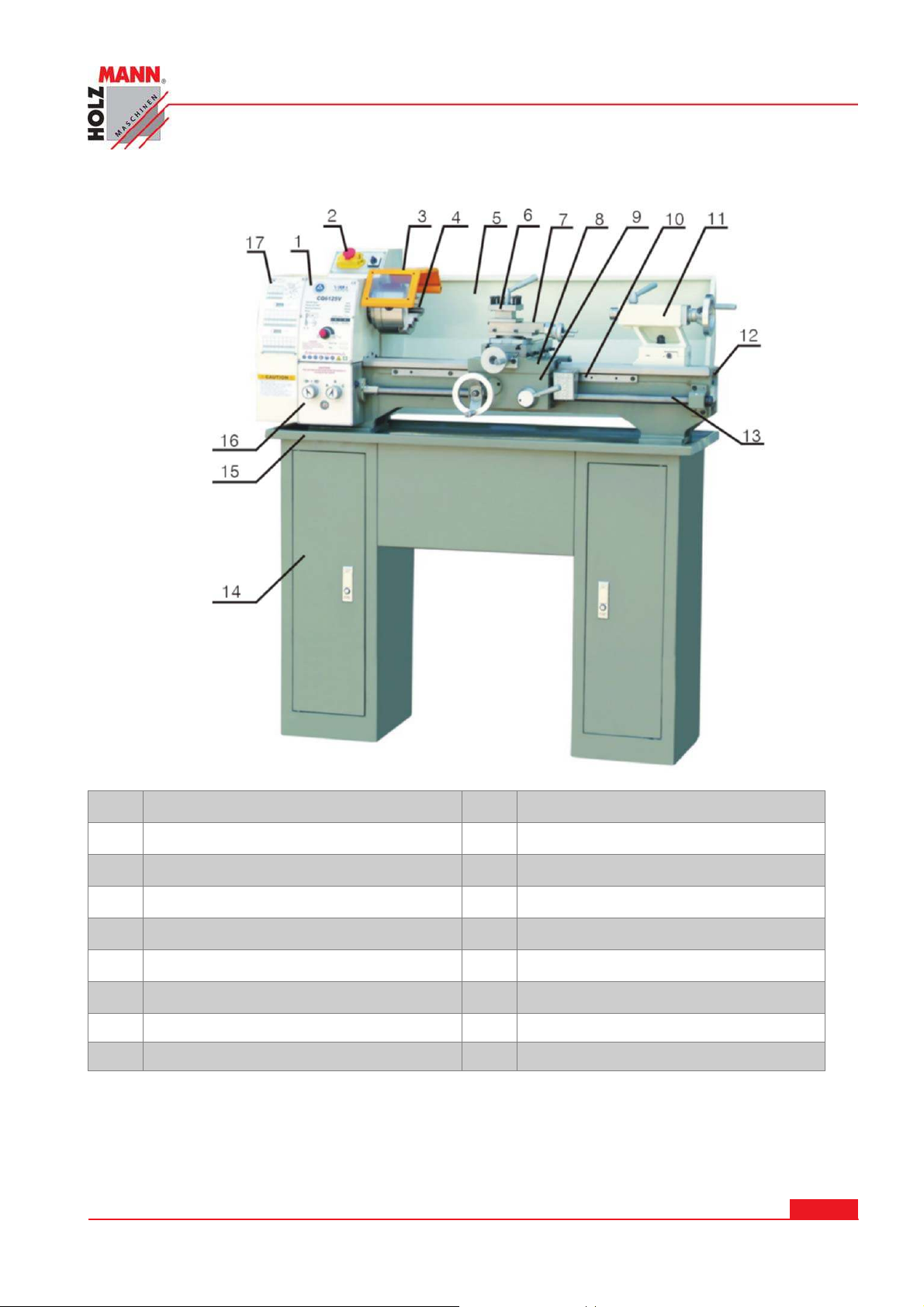
1 1 TECHN I CS
TECHNI CS
1
2
3
4
5
6
7
Emergency button on/off switch 11 tailstock
Headstock 10 Thread indicator
Chuck cover 12 Bed way
3-jaw chuck 13 Lead screw
Splash guard 14 Foot stands
Tool post 15 Oil tray
Top carriage 16 Feed box
8 Lower carriage 17 Quadrant
9 Carriage box
HOLZMANN Maschinen Austria www.holzmann-maschinen.at
Metalldrehmaschine / metal turning lathe ED 750 FDQ
Se it e 2 2
Page 23
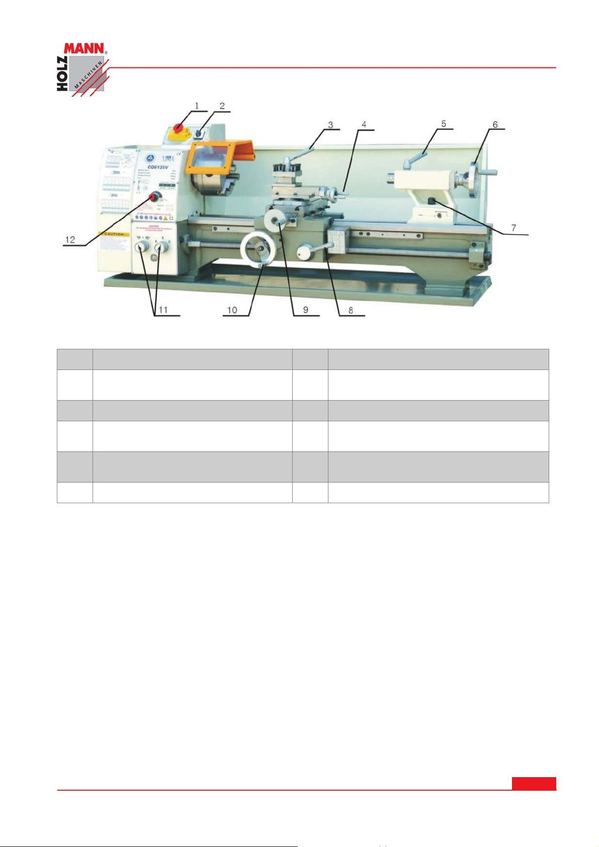
TECHNI CS
Emergency button ON/OFF switch 7 Screw for tailstock fixing
1
Forward and reverse turning switch 8 Handle for starting or stopping of the car-
2
Wrench for the tool-holder 9 Flywheel for feeding the cross slide
3
Flywheel for shifting the tool-holder
4
slide
Handle for tail-spindle fixing 11 Drum (handle) for selection of “thread”
5
Flywheel for tail-spindle shifting 12 Variable speed control switch
6
riage longitudinal shifting while threading
10 Flywheel for manual shifting of the car-
riage in longitudinal direction
(only available on CQ6125V models)
HOLZMANN Maschinen Austria www.holzmann-maschinen.at
Se it e 2 3
Metalldrehmaschine / metal turning lathe ED 750 FDQ
Page 24
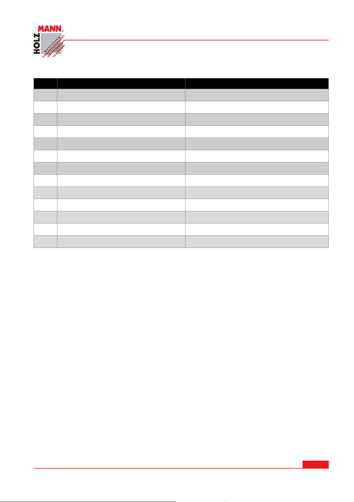
1 1.1 Technical dat a
No. Sp e cification Pa ram eter
Max length of workpiece 750mm
1
Swing over bed 250mm
2
Swing over cross slide 150mm
3
Width of bed 135mm
4
Taper of spindle bore MK3
5
Spindle bore 21mm
6
Number of spindle speed 2 steps
7
Range of spindle speeds 0-2500rpm
8
Range of longitudinal speeds 0.07-0.20mm/rew
9
TECHNI CS
Range of imperial threads 8-56.T.P.I
10
Range of metric threads 0.4-3.5mm
11
Taper of tailstock MK2
12
Main motor 750W (100%), 1,4PS (S6), 230V
13
HOLZMANN Maschinen Austria www.holzmann-maschinen.at
Se it e 2 4
Metalldrehmaschine / metal turning lathe ED 750 FDQ
Page 25

SAFETY GUI DELI N ES
1 2 SAFETY GUI DELI N ES
1 2.1 Proper usa ge
Holzmann Maschinen cannot be held responsible for any injuries or damages if there was performed manipulation or adjustments to the machine.
For a n other usa ge a n d result ing dam a ges or in j u r ies HOLZMAN N M ASCHI NEN
doe sn’t assum e any r e sp onsibility or gu a rantees.
Some dust created by power sanding, sawing, grinding, drilling, and other construction activities contains chemicals known to the State of California to cause cancer, birth defects or other
reproductive harm. Some examples of these chemicals are:
• Lead from lead-based paints.
• Crystalline silica from bricks, cement, and other masonry products.
• Arsenic and chromium from chemically treated lumber.
Your risk from these exposures varies, depending on how often you do this type of work. To
reduce your exposure to these chemicals: work in a well ventilated area, and work with approved safety equipment, such as those dust masks that are specially designed to filter out
microscopic particles.
1 2.2 I ncorrect u sage
Operation of the machine that doesn’t agree with this manual is forbidden!
Operation without the safety devices is not allowed.
You mustn’t remove the safety devices!
Incorrect is the usage for materials which aren’t mentioned in this manual.
Changes of the machine’s construction are forbidden.
For a n other usa ge a n d result ing dam a ges or in j u r ies HOLZMAN N M ASCHI NEN
doe sn’t assum e any r e sp onsibility or gu a rantees.
1 2.3 Safet y inst ructions
Warning labels and/or other labels on the machine must be replaced when they were removed.
Do not operate the m a ch ine at insuff icie nt lig htin g condit ion s.
Do not operate the m a ch ine ou t doors.
Do not operat e the m a chine w hen you are tired, w hen you r con ce n tration is
im pa ire d, a nd/ or u nder the in flu ence of drug s, medica tion o r a lcohol.
Clim bin g onto the m a ch ine is for bid den! H e avy in j urie s by falling dow n or by
tiltin g of t he m achine are possib le.
HOLZMANN Maschinen Austria www.holzmann-maschinen.at
Se it e 2 5
Metalldrehmaschine / metal turning lathe ED 750 FDQ
Page 26
SAFETY GUI DELI N ES
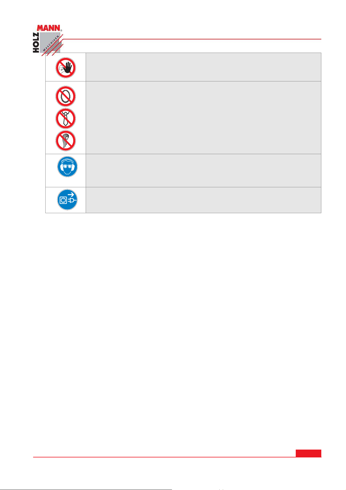
Th e machin e shall be used only by t rain ed person s.
Non aut h orized per sons, e sp ecially childre n , sha ll be kep t aw ay from t h e
w o rk a r ea.
Do n ot w ea r loose clot hin g, long hair openly or lo ose j e w elle ry lik e n e ck laces
etc. w he n o pera t ing the m ach ine
Th e y m ight be ca t ch ed by rota t ing pa r t s and cause ser iou s in j urie s.
Use prop er sa fety clot h ing an d d evice s w he n opera t ing the m a ch ine ( , safe t y
goggles, e ar p rot e cto rs, saf ety shoes …) ! Do not w ea r safe t y g loves for oper atin g because t h ey decrease t he w or k ing accuracy and they m igh t b e pulled
in t o t he saw blade .
Be for e an y m aintena n ce you h ave to discon nect th e pa nel saw from the
pow er sour ce. Nev er u se the plugg ed ca ble fo r t r a nspor t ing or manipulatin g
the m a ch ine.
Operator must read the instruction carefully before operating the machine, and the man-
ager of safety department should assure the operator knows the requirements well.
The operation, maintenance and repair of the machine must be done by qualified person
who have been trained to have the ability to forecast the potential risks. Only safetyconscious persons who are fully aware of the risks can operate the machine.
To those people who assemble, operate, or maintain the machine must be confirmed to
have read and understood the operating instructions.
After stopping the machine, the tool will still run for a period of time due to inertia, do not
open the tool guard and touch the tool with your hand before it comes to stop running.
Do not detach or modify any part of the safety guard. The machine should be discon-
nected from the power supply during maintenance or repair.
W ARNI NG! NEVER CONTACT THE CUTTERS AN D OTHER D RI VI N G PARTS W I TH
HAN D S I F THEY ARE STI LL MOV I N G
Assign special persons to operate, maintain and adjust the machine.
Operate the machine in technically perfect condition. Only the producer or qualified person
can completely repair the machine.
Stop the machine immediately if abnormal phenomena appear, check and repair the ma-
chine by specialized persons in time.
Disassembly and assembly the machine with the hoisting equipment, which is of enough
load capacity.
Observe all safety instructions and warnings attached to the machine, make sure they are
always complete and perfectly legible.
Do safety inspection before operating. Ensure the stroke limit switches, stop block and
emergency stop button safe and reliable.
Reinstall the removed guards and safety devices in place after maintaining.
HOLZMANN Maschinen Austria www.holzmann-maschinen.at
Metalldrehmaschine / metal turning lathe ED 750 FDQ
Se it e 2 6
Page 27

SAFETY GUI DELI N ES
Do maintenance or adjustment only after switching the machine off and disconnecting the
machine from the power source.
Always keep children away from the machine. Operating personal must be at least 18
years old.
Do not wear loose clothing, gloves, neckties or jewelry (rings, watches, etc). Keep the
sleeves and the edges of the work uniform tight. Always be sure to wear safety goggles
and wear safety shoes during operation.
Put the long hair into a safety hat during operation no matter the operator is a man or a
woman.
It is recommended to wear suitable hearing protection equipment when necessary to re-
duce the risk of hearing loss.
Provide adequate light around the machine, and keep the perimeter around the machine
dry, clean and in good order. In addition, do not place anything near the machine; otherwise it becomes an obstacle during operation.
Do not remove the guards from their working place during operation.
Disconnect the power supply before leaving the machine.
Restart the machine only after the guards and safety devices are replaced to their position
and in their good function.
Do not place tools, work pieces, or other items, which not be in use on the machine, espe-
cially on the moving parts.
Clamp workpiece and tools completely and reliably and take off the wrench from chuck be-
fore starting the spindle running.
Stop the machine before adjusting the position of the coolant nozzles.
Do not use compressed air to remove dust and chips etc. deposited on the machine,
switchboard, control unit etc.
Both operators and the maintenance men should read the descriptions carefully on the
caution plate attached on the machine. They should observe the OPERATION MANUAL in
their work. During operation and maintenance, care should be taken so that this caution
plate is not dirtied or damaged.
Always bear in mind where the emergency stop button is so that you can operate it with-
out delay in case of an emergency.
Start the machine according to the starting procedures strictly.
Keep your hands away from the moving parts of the machine during operation.
Prior to starting test operation, read this manual carefully so as to be familiar with this
machine.
Contact the manufacturer if for some reason the OPERATION MANUAL should become unreadable.
Accessories: Only use accessories recommended by Holzmann Maschinen.
HOLZMANN Maschinen Austria www.holzmann-maschinen.at
Se it e 2 7
Metalldrehmaschine / metal turning lathe ED 750 FDQ
Page 28

SAFETY GUI DELI N ES
1 2.4 Safet y inst ructions for t he ED7 50 FD Q
All lathe operators must be constantly aware of the safety hazards that are associated with using
the lathe and must know all safety precautions to avoid accidents and injuries.
Some important safety precautions to follow when using the lathe are:
12. Correct dressing is important, remove rings and watches, roll sleeves above elbows.
13. Always stop the lathe before making adjustments.
14. Do not change spindle speeds until the lathe comes to a complete stop.
15. Handle sharp cutters, centers, and drill with care.
16. Remove chuck keys and wrenches before operating
17. Always wear protective eye protection.
18. Handle heavy chuck with care and protect the lathe ways with a block of wood when installing
a chuck.
19. Know where the emergency stop is before operating the lathe
20. Use pliers or a brush to remove chips and swarf, never your hands.
21. Never lean on the lathe.
22. Never lay tools directly on the lathe ways. If a separate table is not available, use a wide
board with a cleat on each side to lay on the ways.
23. Keep tools overhang as short as possible.
24. Never attempt to measure work while it is running
25. Never file lathe work unless the file has a handle.
26. File left-handed if possible
27. Protecting the lathe ways when grinding or filing.
28. Use two hands when sanding the work piece. Do not wrap sand paper or emery cloth around
the work piece.
HOLZMANN Maschinen Austria www.holzmann-maschinen.at
Se it e 2 8
Metalldrehmaschine / metal turning lathe ED 750 FDQ
Page 29
DESCRI PTI ON OF TH E MAI N UNI TS
1 3 DESCRI PTI ON OF THE MAI N UNI TS
1 3.1 Head stock
The head stock is mounted on the machine corp. the rotation motion to this gear box is transferred through V-belts and belt pulley from an el. motor mounted on the guide way.
1 3.2 Qua dr ant
The quadrant is destinated to transfer the motion from the head stock to the feed box through
some change gears. It is mounted in the quadrant box. The latter is closed by a cover.
1 3.3 Feed box
The feed box is fixed to the face side of the machine corp.—just below the head stock. It includes
all the mechanisms, by the help of which is effected the adjustment for selection of the feed or
thread pitches.
Required adjustments for the different values of the feed or thread pitch are realized by the help
of respective drums, located on the front part of the feed box.
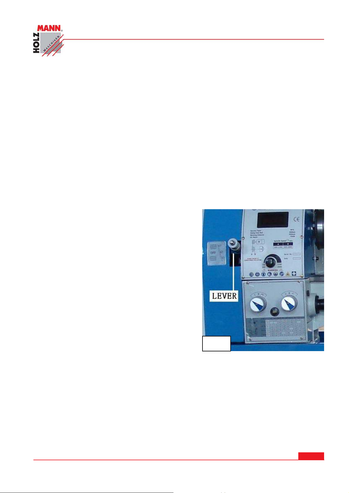
1 3.4 Feed dir e ction leve r
Putting this lever in the top hole moves the carriage
left along the bed or the top slide toward the workpiece while spindle is turning counter-clockwise .
Putting the lever in the foot hole moves the carriage
right along the bed or the top slide away the workpiece
while spindle is turning counter-clockwise . If putting
the lever in the middle hole change gears and feed
screw is not turning while spindle is turning .
Fig. 1
1 3.5 Carriage g r ou p and it s m echan ism s
The carriage group is festinated for fixing and driving the cutting too. It includes five basic parts:
carriage box, carriage board, lower slide, cross piece and upper (top) slide.
1 3 .5 .1 Carria ge box
The carriage box is mounted on the carriage board. It contain the mechanisms that are used for
driving the carriage longitudinal and cross feed, as well as the mechanism for engagement of the
nut to the lead-screw while threading and the mechanism for manual feed of the carriage.
HOLZMANN Maschinen Austria www.holzmann-maschinen.at
Metalldrehmaschine / metal turning lathe ED 750 FDQ
Se it e 2 9
Page 30
DESCRI PTI ON OF TH E MAI N UNI TS
1 3 .5 .2 Carria g e boa r d
The carriage board is mounted on the corp. guide ways. All the rest parts of the carriage group
are fixed to this carriage board.
The lower slide moved on the guide ways of the carriage board in transverse direction.
When short cones have to turned by hand, the cross piece may be swiveled at 90° towards the
lower slide in both directions and be fixed in the required position by the help of suitable bolts
and nuts.
The top slide on which the four-position tool holder is
mounted, may be shifted only by hand in the direction
of the cross-piece.
Thus you may obtain longitudinal, cross and combined
feed for the cutting tool.
NOTI CE:
Do not simultaneously engage the feed lever and the
threading lever . Doing so will damage the lathe .
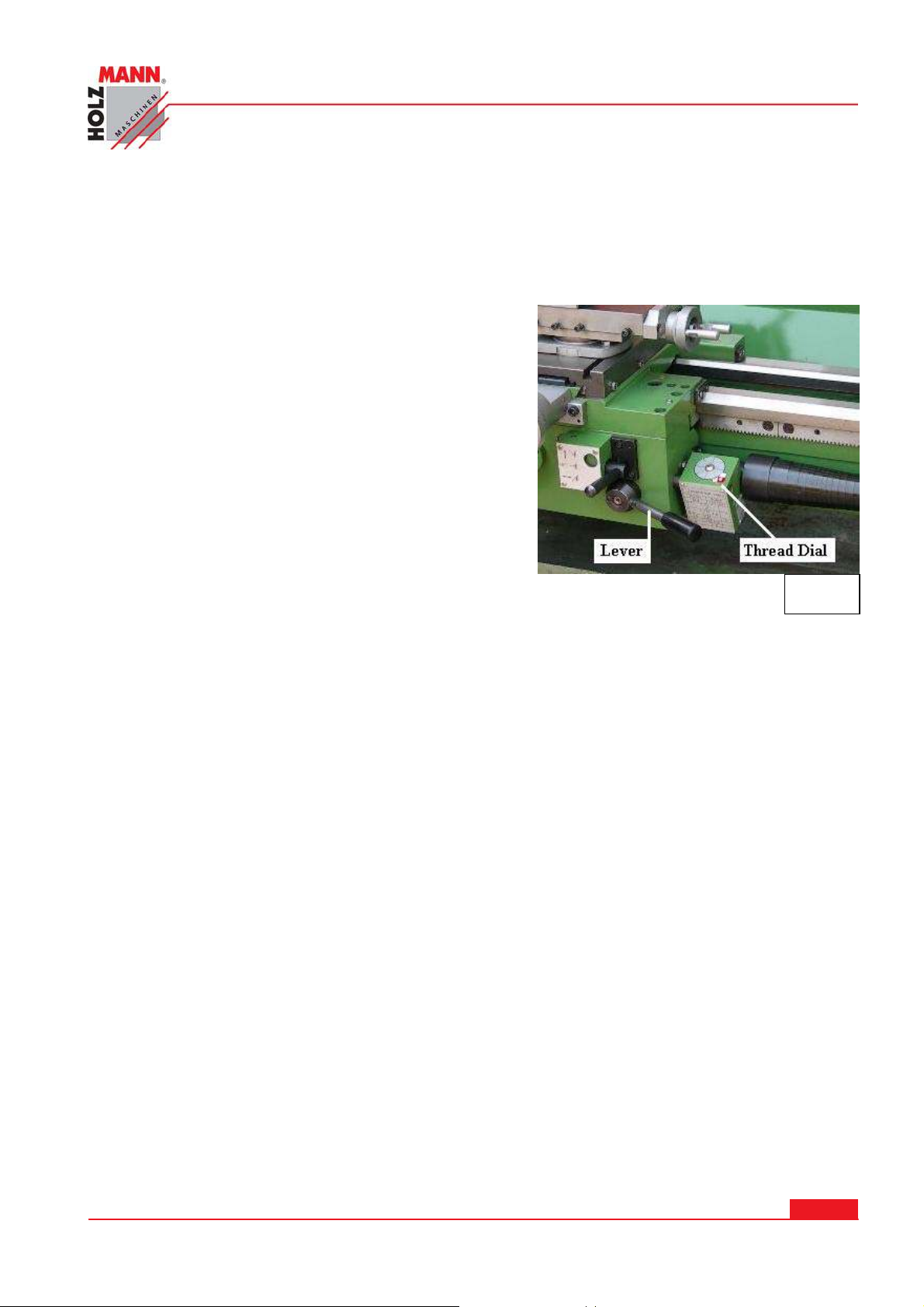
Half Nut Le v e r – This lever compresses and releases
the half nut engages the leadscrew . The lever is only
engaged while turning threads in stock . A lockout
device featured in the lever mechanism engages when
the feed selector is used.
1 3.6 Thr e ad indicat or
Fig. 2
This device is mounted to the carriage box (disengaged to the driving screw) for getting into
thread pitch
1 3.7 Ta il stock
The tailstock is clamped to the corp. guide ways. It is designed for working piece clamping during
machining between centers for drilling operations with manual feed of the tool.
1 3.8 Rests
The two types are with sliding quills. The steady rest is fixed to the corp. guide ways and the follow rest to the carriage board.
.
HOLZMANN Maschinen Austria www.holzmann-maschinen.at
Se it e 3 0
Metalldrehmaschine / metal turning lathe ED 750 FDQ
Page 31

I NSTALLATI ON
1 4 I NSTALLATI ON
1 4.1 Tra nsportat ion
The machine is transported in a special wooden case (or with foot stands separately packed in
carton), being fixed to the base of the case or slide by suitable bolts. Some of the accessories are
mounted on the lathe well fixed and the other packed in a separate box or directly fixed on the
case base.
The places where the ropes or chains have to be passed during handling of the packed machine
are marked on the packing. Be aware of the heavy side while you are handling the machine with
forklift.
1 4.2 Un pa cking
After the machine had been unpacked, check carefully its general condition, as well as the availability and condition of all the accessories, shown in the packing list.
1 4.3 Handling
Unpacked machine shall be handled only by the help of a suitable crane. Before passing the ropes
over the lathe, pull out the tailstock and carriage and fix them in the rear hand position so that
when lifting the machine you will obtain required balancing. When handling the machine never
strike or hit it sharply because this may affect the machine accuracy—irrespective of whether
there are or not may visible defects.
Since the paint on some part of the machine may be damaged during handling, place protective
pads of fabrics or other suitable material on the respective places.
1 4.4 Pre pa ration
Before mounting the machine on the predetermined place, clean it carefully from the protective
oil. Respective machine surface shall be washed by the help of pure naphtha or benzine.
This protective oil shall not be removed by hard objects or solvent that may damage the metal
surface or paint of the machine. Well-cleaned surfaces are dried by the help of dry threads and
covered with pure machine oil. Remove the end gear cover. Clean all components of the end
gear assembly and coat all gears with heavy, non-slinging grease.
1 4.5 Conn e ction t o t he ele ctronical supply sour ce
Check whether the data on the el. panel scheme (voltage and frequency of the supply source)
correspond to the available.
Make sure the lathe in properly grounded.
Conn e ction of t h e lat he and all other e lectrical w ork m ay only be carried out by an authorized electrician!
Fa ilu r e to co m ply may cause serious in j u r y and damage t o the m a chinery and prop erty!
HOLZMANN Maschinen Austria www.holzmann-maschinen.at
Metalldrehmaschine / metal turning lathe ED 750 FDQ
Se it e 3 1
Page 32
1 5 OPERATI ON I NSTRUCTI ON S
NOTE: Make sure the variable speed control switch is in zero
position in counter-clockwise direction before turning on the
lathe!
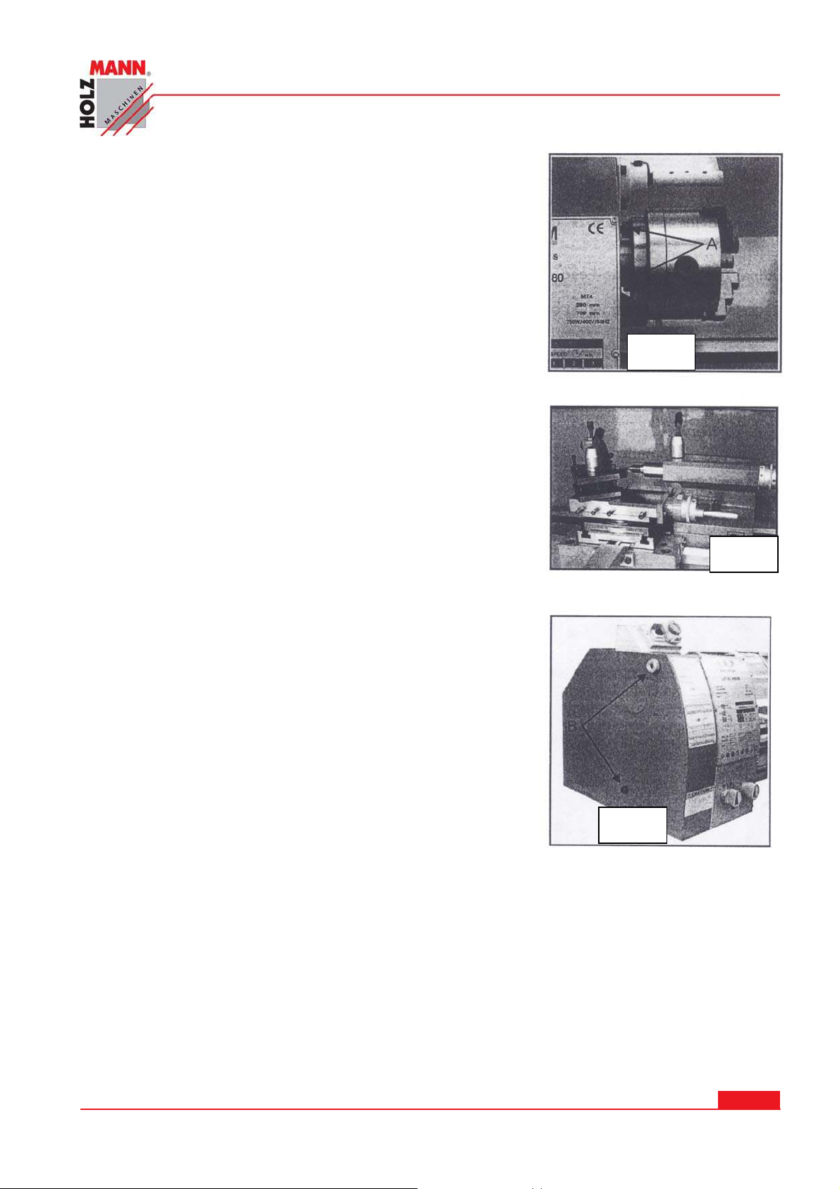
1 5.1 Replacem ent of chuck
The head spindle holding fixture is cylindrical. Loose three set
screws and nuts (A, Fig.3, only two are shown) on the lathe
chuck flange to remove the chuck. Position the new chuck and
fix it using the same set screws and nuts.
1 5.2 Tool se t -up
Clamp the turning tool into the tool holder.
The tool must be clamped firmly. When turning, the tool has a
tendency to bend under the cutting force generated during
the chip formation. For best results, tool overhang should be
kept to a minimum of 3/8” or less.
The cutting angle is correct when the cutting edge is in line
with the center axis of the work piece. The correct height of
the tool can be achieved by comparing the tool point with the
point of the center mounted in the tailstock. If necessary, use
steel spacer shims under the tool to get the required height.
(Fig.4)
OPERATI ON I NSTRUCTI ONS
Fig. 3
Fig.3
Fig.4
Fig. 4
1 5.3 Cha nge speed
5. Unscrew the two fastening screws (B, Fig.5) and remove
the protective cover.
6. Adjust the V-belt into the corresponding position.
7. Tighten the tension pulley and fasten the nut again.
ATTENTI ON:
Make sure the tension of the V-belt is correct.
Excessive or insufficient tension can cause damage.
HOLZMANN Maschinen Austria www.holzmann-maschinen.at
Metalldrehmaschine / metal turning lathe ED 750 FDQ
Fig.5
Fig. 5
Fig.6
Se it e 3 2
Page 33
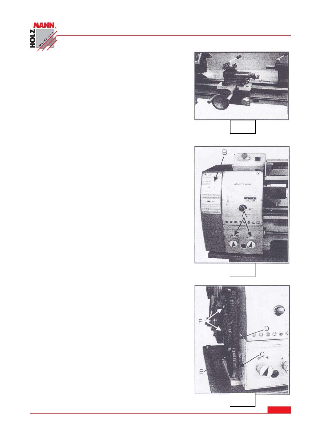
1 5.4 M a nual t urning
Apron travel, cross travel, and top slide hand wheel can
be operated for longitudinal or cross feeding. (Fig.7)
1 5.5 Lon gitudinal turning w it h a u to-fee d
OPERATI ON I NSTRUCTI ONS
Fig. 7
Set the selector knob (A, Fig.8) to select the feed direction and feed speed. Only available on CQ6125V models.
Use the table (B, Fig.8) on the lathe for selecting the feed
speed or the thread pitch, Adjust the change gear if the
required feed or thread pitch cannot be obtained with the
installed gear set.
1 5.6 Cha nge gea rs replacem ent
10. Disconnect the machine from the power source.
11. Unscrew the two fastening screws and remove the
protective cover.
12. Loosen the locking screw (C, Fig.8) on the quadrant.
13. Swing the quadrant (D, Fig.8) to the right.
14. Unscrew the bolt (E, Fig.8) from the leadscrew or the
square bolts (F, Fig.8) from the quadrant bolts in order to remove the change gears from the front.
15. Install the gear couples according to the thread and
feed table (Fig.9) and screw the gearwheels onto the
quadrant again.
16. Swing the quadrant to the left until the gearwheels
have engaged again.
17. Readjust gear backlash by inserting a normal sheet
of paper as an adjusting or distance aid between the
gearwheels.
18. Immobilize the quadrant with the locking screw.
19. Install the protective cover of the headstock and reconnect the machine to the power supply.
HOLZMANN Maschinen Austria www.holzmann-maschinen.at
Fig.7
Fig. 6
Fig. 8
Fig.8
Fig. 9
Se it e 3 3
Metalldrehmaschine / metal turning lathe ED 750 FDQ
Page 34
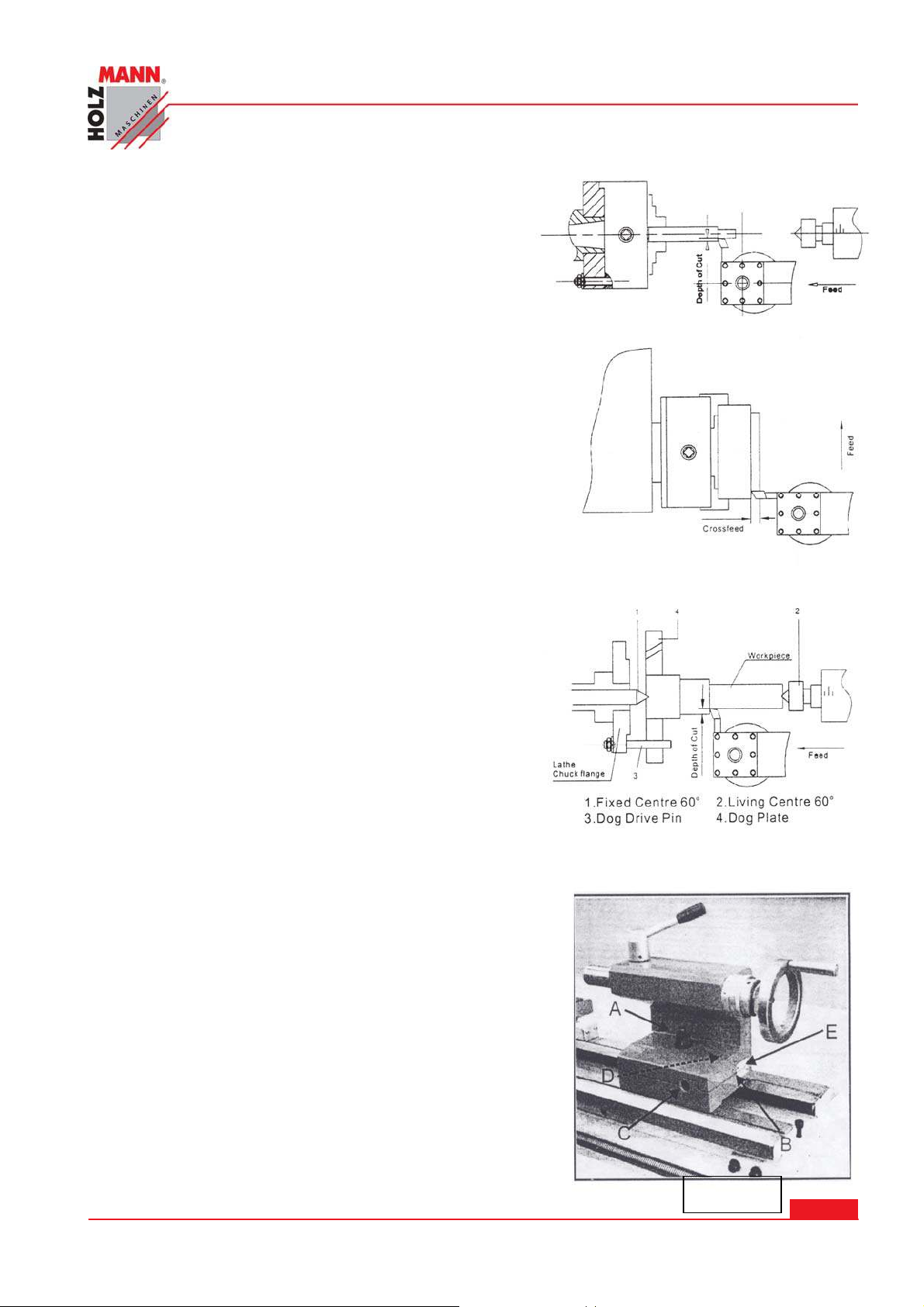
1 5.7 straight turning ( Fig.1 0 )
In the straight turning operation, the tool feeds parallel
to the axis of rotation of the workpiece. The feed can
be either manual by turning the handwheel on the
lathe saddle or the top slide, or by activating the
automatic feed. The cross feed for the depth of cut is
achieved using the cross slide.
1 5.8 facing and r e ce sses ( Fig.1 1 )
In the facing operation, the tool feeds perpendicular to
the axis of rotation of the workpiece. The feed is made
manually with the cross slide handwheel. The cross
feed for cut depth is made with the top slide or lathe
saddle.
1 5.9 Turning be tw een ce nters ( Fig.1 2 )
OPERATI ON I NSTRUCTI ONS
Fig.10
For turning between centers, it is necessary to remove
the chuck from the spindle. Fit the M.T.3 center into
the spindle nose and the M.T.2 center into the tailstock. Mount the workpiece fitted with the driver dog
between the centers. The driver is driven by a catch or
face plate.
Note: Always use a small amount of grease on the tailstock center to prevent center tip from overheating.
1 5.1 0 Tape r t urning using tailstock off-
se t
Work to a side angle of 5 can be turned by off-setting
the tailstock. The angle depends on the length of the
work piece.
To off-set the tailstock, loosen locking screw (A,
Fig.13). Unscrew the set screw (B, Fig.13) on right end
of the tailstock. Loosen the front adjusting screw
(C,Fig.13) and take up the same amount by tightening
the rear adjusting screw (D,Fig.13) until the desired
taper has been reached. The desired cross-adjustment
can be read off the scale. (E,Fig.13). First retighten the
set screw (B,Fig.13) and then the two (front and rear)
adjusting screw to lock the tailstock in position. Retighten the locking screw (A,Fig.13) of the tailstock.
The work piece must be held between to centers and
driven by a faceplate and driver dog.
After taper turning, the tailstock should be returned to
its original position according to the zero position on
the scale of tailstock. (E,Fig.13)
HOLZMANN Maschinen Austria www.holzmann-maschinen.at
Fig.11
Fig.12
Fig.13
Metalldrehmaschine / metal turning lathe ED 750 FDQ
Se it e 3 4
Page 35
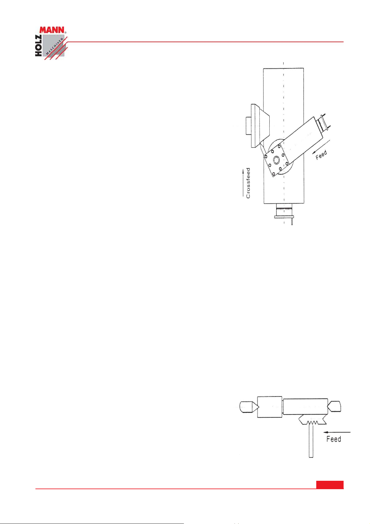
1 5.1 1 taper turning by setting the top slide
By angling the top slide, tapers may be turned manually with
the top slide. (Fig.14)
Rotate the top slide to the required angle. A graduated scale
permits accurate adjustment of the top slide. The cross feed
is performed with the cross slide. This method can only be
used for short tapers.
1 5.1 2 Thre ad cutting
Set the machine up to the desired thread pitch (according to
the threading chart, (Fig. 14). Start the machine and engage
the half nut. When the tool reaches the part, it will cut the
initial threading pass. When the tool reaches the end of the
cut, stop the machine by turning the motor off and at the
same time back the tool out of the part so that it clears the
thread. Do not disengage the half nut lever. Reverse the
motor direction to allow the cutting tool to traverse back to
the starting point. Repeat these steps until you have obtained the desired results.
OPERATI ON I NSTRUCTI ONS
1 5 .1 2.1 Exam ple: Male t hread
The workpiece diameter must have been turning to the
diameter of the desired thread.
The work piece requires a chamfer at the beginning of
the thread and an undercut at the thread runout.
The speed must be as low as possible.
The change gears must have been installed according to
the required pitch.
The thread cutting tool must be exactly the sample
shape as the thread, must be absolutely rectangular
and clamped so that it coincides exactly with the turning center.
The thread is produced in various cutting steps so that
the cutting tool has to be turning out of the thread
completely (with the cross slide) at the end of each cutting step.
The tool is withdrawn with the leadscrew nut engaged
by inverting the change-over switch..
Stop the machine and feed the thread cutting tool in
low cut depths using the cross slide.
Before each passage, place the top slide approximately
0.2 to 0.3mm to the left and right alternately in order to
cut the thread free. This way, the thread cutting tools
cuts only on one thread flank with each passage. Keep
cutting the thread free until you have almost reached
the full depth of thread.
Fig.14
Fig.15
HOLZMANN Maschinen Austria www.holzmann-maschinen.at
Se it e 3 5
Metalldrehmaschine / metal turning lathe ED 750 FDQ
Page 36
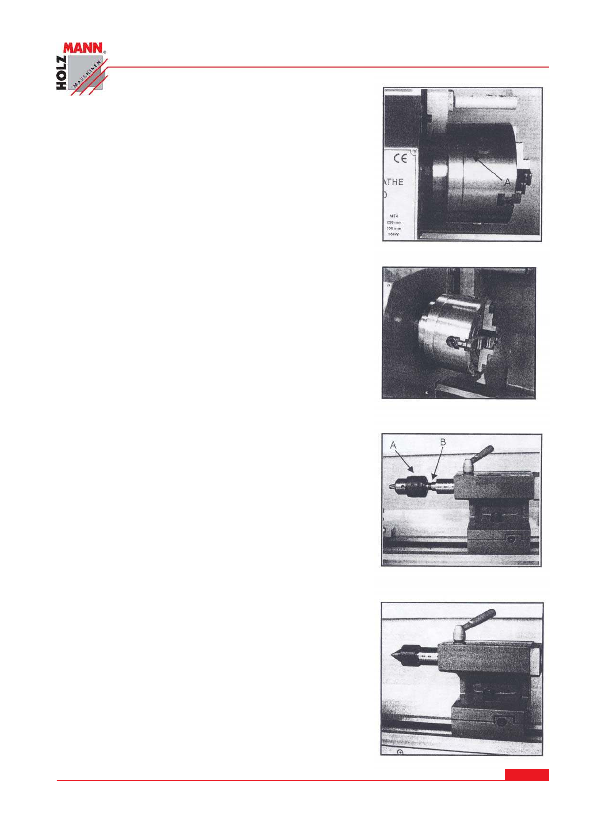
1 6 ACCESSORI ES
1 6.1 THREE JAW UNI VERSAL CHUCK
Using this universal chuck, round, triangular, square, hexagonal octagonal, and twelve-cornered stock maybe
clamped. (Fig.16)
Note: new lathes have very tight fitting jaws. This is necessary to ensure accurate clamping and long service life. With
repeated opening and closing, the jaw adjusts automatically
and their operation becomes progressively smoother.
Note:
For the original 3-jaw chuck that mounted on the lathe, the
factory has mounted the chuck in the best way to Guarantee
the holding accuracy with two “0” mark (A, Fig.16) showed
on the chuck and chuck flange.
Three are two types of jaws: internal and external jaws.
Please note that the number of jaws fit with the number inside the chuck’s groove. Do not mix them together. When
you are going to mount them, please mount them in ascending order 1-2-3, when you are going to take them out, be
sure to take them out in descending order 3-2-1,one by one.
After you finished this procedure, rotate the jaws to the
smallest diameter and check that the three jaws are well
fitted.
ACCESSORI ES
Fig.16
Fig.17
1 6.2 FOUR JAW I NDEPEN DENT CHUCK
This special chuck has four independently adjustable chuck
jaws. These permit the holding of asymmetrical pieces and
enable the accurate set-up of cylindrical pieces. (Fig.18)
1 6.3 D RI LL CH UCK ( Optiona l)
Use the drill chuck to hold centering drills and twist drills in
the tailstock. (A,Fig.19)
1 6.4 M ORSE TAPER ARBOR ( Opt ional)
An arbor is necessary for mounting the drill chuck in the tailstock. It has a No.2 Morse taper. (B,Fig.19)
1 6.5 LI VE CENTER ( Optional)
The live center is mounted in ball bearings. Its use is highly
recommended for turning at speeds in excess of 600 rpm.
(Fig.19)
Fig.18
HOLZMANN Maschinen Austria www.holzmann-maschinen.at
Fig.19
Se it e 3 6
Metalldrehmaschine / metal turning lathe ED 750 FDQ
Page 37
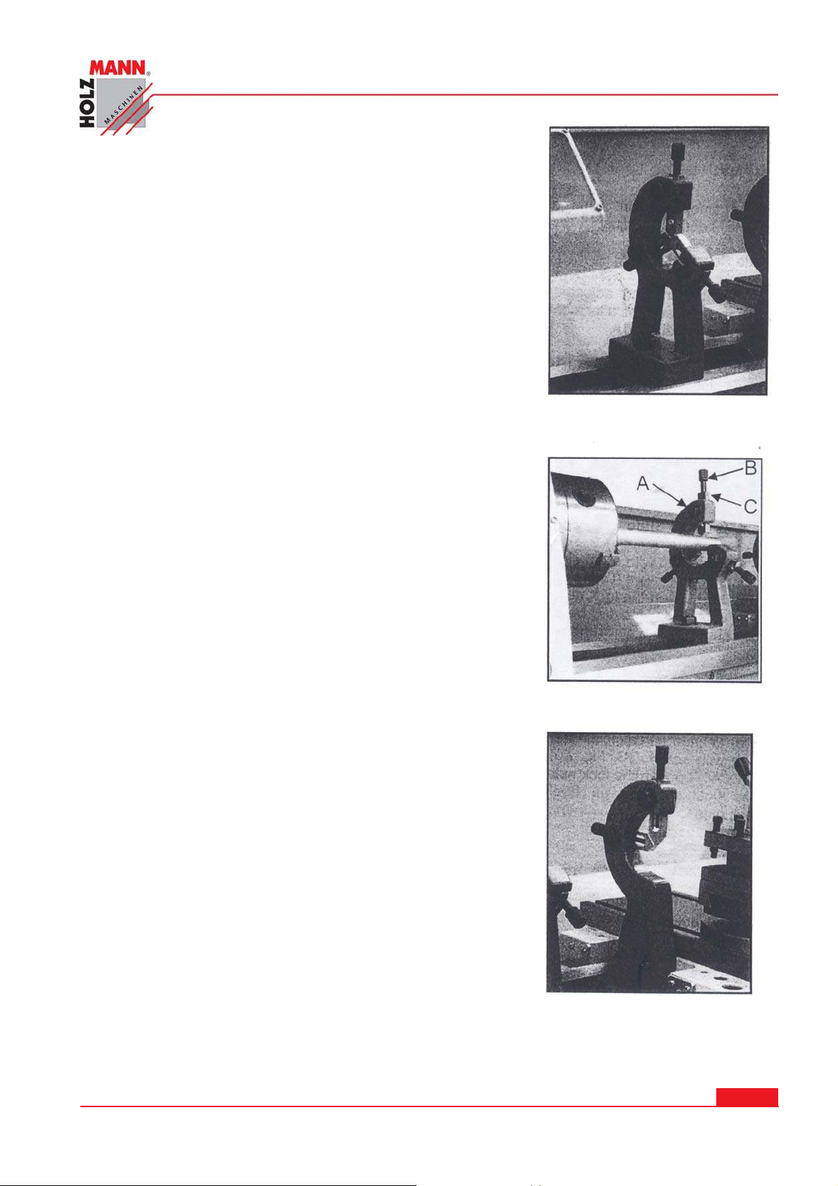
1 6.6 STEADY REST
The steady rest serves as a support for shafts on the free
tailstock end. For many operations the tailstock cannot be
used as it obstructs the turning tool or drilling tool, and
therefore, must be removed from the machine. The steady
rest, which function as an end support, ensures chatter-free
operation. The steady rest is mounted on the bedways and is
secured from below with a locking plate. The sliding fingers
require continuous lubrication at the contact points to prevent
premature wear. (Fig.20)
1 6.7 SETTI N G TH E STEADY REST
Loosen three hex nuts. (A,Fig.21)
Loosen knurled screw (B,Fig.21) and open the sliding fingers.
(C,Fig.21) until the steady rest can be moved with its finger
around the workpiece. Secure the steady rest in position.
Tighten knurled screws so that fingers are snug but not tight
against the workpiece. Tighten three nuts (A,Fig.21). Lubricate the sliding points with machine oil.
When, after prolonged operation, the jaw show wear, the tips
of the fingers may be filed or remilled.
ACCESSORI ES
Fig.20
1 6.8 FOLLOW REST
The follow rest is mounted on the saddle and follow the
movement of the turning tool. Only two sliding fingers are
required. The place of the third finger is taken by the turning
tool. The follow rest is used for turning operations on long,
slender workpieces. It prevents flexing of the workpiece under pressure from the turning tool. (Fig.22)
Set the fingers snug to the workpiece but not overly tight.
Lubricate the fingers during operation to prevent premature
wear.
Fig.21
HOLZMANN Maschinen Austria www.holzmann-maschinen.at
Fig.22
Se it e 3 7
Metalldrehmaschine / metal turning lathe ED 750 FDQ
Page 38
MECHANI SM’S ADJUSTMENT
1 7 MECH ANI SM ’S ADJUSTM ENT
All the mechanisms are adjusted and tested in the producer’s plant. After a prolonged exploitation, some of the mechanisms have to be readjusted because of the wearing off of the friction
surfaces. The adjustment and setting of the different mechanisms shall be effected after each
machine repair too. It is recommended these adjustments to be performed by qualified specialists in respective service.
1 7.1 M AI N SPI ND LE BEARI N GS
The main spindle bearings are adjusted at the factory. If end play
becomes evident after considerable use, the bearings may be
adjusted.
Caution: excessive tightening or preloading will damage the
bearings.
Fig.23
Fig.23
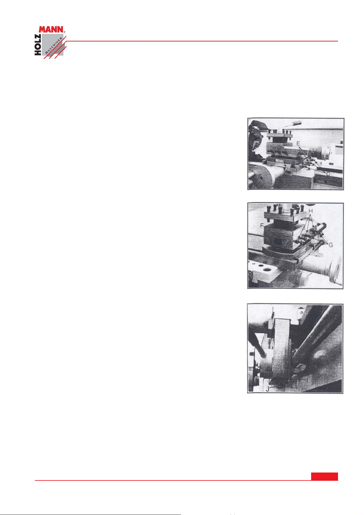
1 7.2 ADJUSTMEN T OF CROSS SLI DE
The cross slide is fitted with a gib strip (C, Fig.24) and can be
adjusted with screws (D,Fig.24) fitted with lock nuts. (E,Fig.24)
Loosen the lock nuts and tighten the set screws until slide moves
freely without play. Tighten lock nuts to retain adjustment.
1 7.3 ADJUSTMEN T OF TOP SLI DE
The top slide is fitted with a gib strip (F, Fig.25) and can be adjusted with screws (G,Fig.25) fitted with lock nuts. (H, Fig.25)
Loosen the lock nuts and tighten the set screws until slide moves
freely without play. Tighten lock nuts to retain adjustment.
1 7.4 ADJUSTMENT OF HALF N UT GUI DE
Loosen the nut (I, Fig.26) on the right side bottom of the apron
and adjust the control screws (J, Fig.26) until both half nuts
move freely without play. Tighten the nut.
Fig.24
HOLZMANN Maschinen Austria www.holzmann-maschinen.at
Fig.25
Se it e 3 8
Metalldrehmaschine / metal turning lathe ED 750 FDQ
Page 39
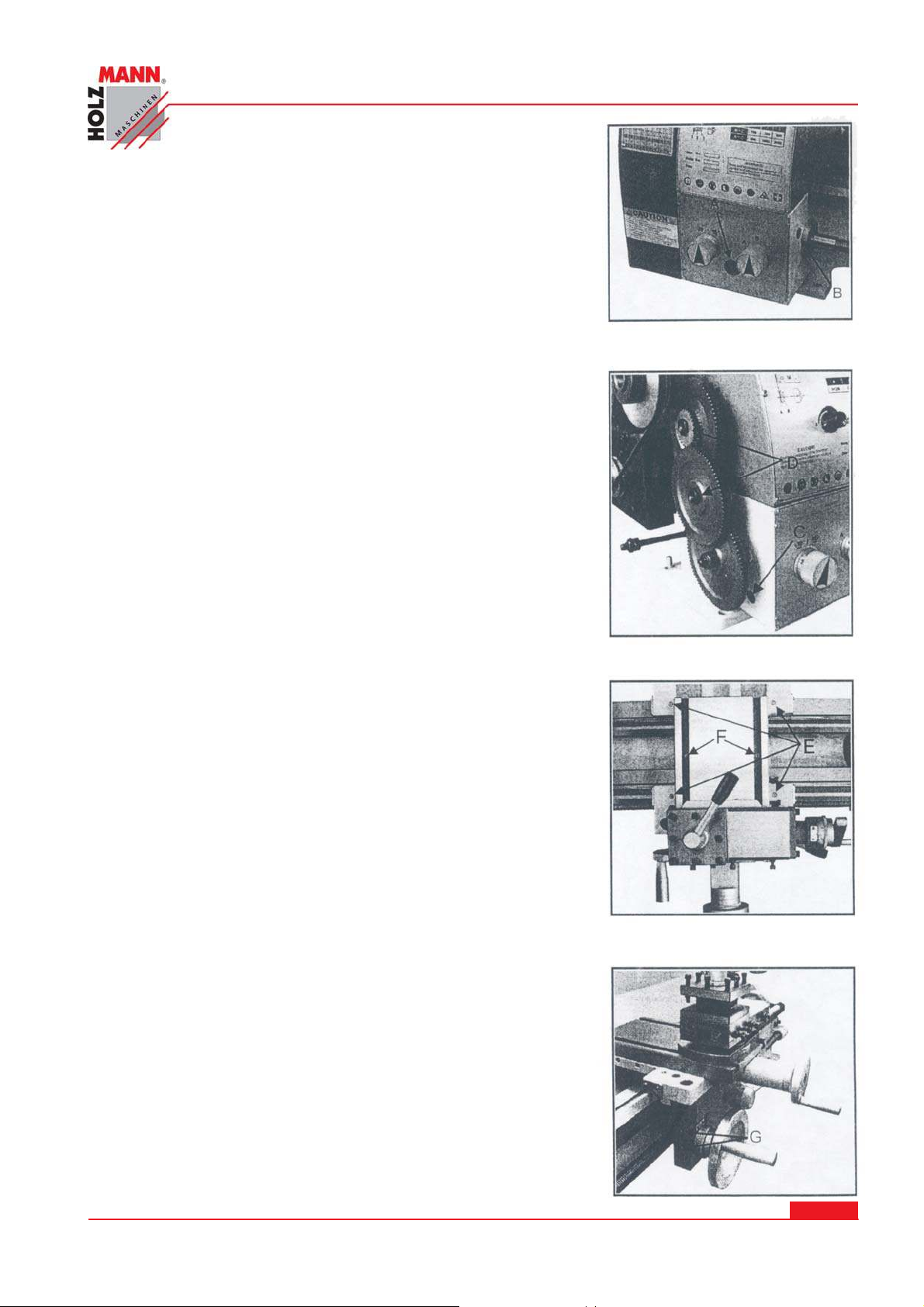
1 8 LUBRI CATI ON
The trouble-free operation on the lathe depends on its careful
servicing. Of special importance is the regular lubrication of
all machine-operating parts with the recommended lubricants.
FAI LURE TO COM PLY M AY CAUSE SERI OUS D AMAGE!
NOTES:
Lubricate all slideways lightly before every use. Lubricate the
change gears and the leadscrew slightly with a lithium-based
Grease.
1 8.1 H EADSTOCK
Oil must be up to indicator mark in oil sight glass (A, Fig27).
Top off with Mobilgear 627 or equivalent. Fill by pulling plug
(B,Fig. 27). To drain, remove drain plug on the right slide of
headstock (C,Fig.28). Drain oil completely and refill after the
first three months of operation. Then, change oil in the
headstock annually.
Fig.28
LUBRI CATI ON
Fig.26
1 8.2 CH AN GE GEAR
Lubricate two oil ports (D, Fig.28) on the gear shafts with
20W machine oil once daily.
1 8.3 CARRI AGE
Lubricate four oil ports (E, Fig.29) with 20W machine oil once
daily.
1 8.4 CROSS SLI DE
Lubricate two oil ports (F, Fig.29) with 20W machine oil once
daily.
1 8.5 APRON
Lubricate two oil ports (G,Fig.30) with 20w machine oil once
daily.
Fig.29
Fig.27
Fig.30
Fig.28
Fig.31
HOLZMANN Maschinen Austria www.holzmann-maschinen.at
Fig.30
Metalldrehmaschine / metal turning lathe ED 750 FDQ
Se it e 3 9
Page 40
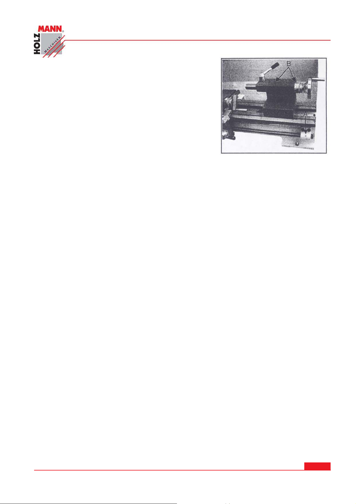
1 8.6 LEAD SCREW
Lubricate the oil port (A, Fig.31) with 20w machine oil once
daily.
1 8.7 TAI LSTOCK
Lubricate two oil ports (B,Fig.31) with 20w machine oil
once daily.
LUBRI CATI ON
Fig.31
HOLZMANN Maschinen Austria www.holzmann-maschinen.at
Se it e 4 0
Metalldrehmaschine / metal turning lathe ED 750 FDQ
Page 41

MACH I N E CARE AN D MAI TENANCE
1 9 MACHI N E CARE AND M AI TEN ANCE
Lathes are highly accurate machine tool designed to operate around the clock if properly operated
and maintained. Lathes must be lubricated and checked for adjustment before operation. Improper lubrication or loose nuts and bolts can cause excessive wear and dangerous operating
conditions.
1. The lathe ways are precision ground surfaces and must not be used as table for other tools
and should be kept clean of grit and dirt.
2. The lead screw and gears should be checked frequently for any metal chips that could be
lodged in the gearing mechanisms.
3. Check the lathe prior to operation for any missing parts or broken shear pins. Refer to the
manual before attempting to lift the lathe.
4. Newly installed lathe should be properly leveled before any operation to prevent vibration and
wobble.
5. When the lathe is transported out of a normal shop environment should be protected from
dust, excessive heat, and very cold conditions.
6. Change the lubricant frequently if working in dusty conditions.
7. In hot working areas, use care to avoid overheating the motor of damaging any seals.
8. Operate the lathe at slower speeds than normal when working in cold environments.
9. Lubricate all slide ways lightly before every using. The change gears and the leads crew must
also be lightly lubricated with lithium base grease.
10. During the operation, the chips which falls onto the sliding surface should be cleaned timely,
and the inspection should be often made to prevent chips falling into the position between
the machine tool saddle and lathe bed guide way. Asphalt felt should be cleaned at certain
time.
11. After the operation every day, eliminate all the chips and clean different part of the machine
tool and apply machine tool oil to prevent rusting.
12. In order to maintain the machining accuracy, take care of the center, the surface of the machine tool for the chuck and the guide way and avoid mechanical damage and the wear due
to improper guide.
13. If the damage is found, the maintenance should be done immediately.
ATTENTI ON: before performing any checking, repairing or maintenance operation, switch off the
main switch and make an additional check to ensure that the machine is not under voltage.
Oil, grease and cleaning agents are pollutants and must not be disposed of through the drains or
in normal refuse Dispose of those agents in accordance with current legal requirements on the
environment. Cleaning rags impregnated with oil, grease and cleaning agents are easily inflammable. Collect cleaning rags or cleaning wool in a suitable closed vessel and dispose of them in an
environmentally sound way-do not put them with normal refuse!
HOLZMANN Maschinen Austria www.holzmann-maschinen.at
Metalldrehmaschine / metal turning lathe ED 750 FDQ
Se it e 4 1
Page 42
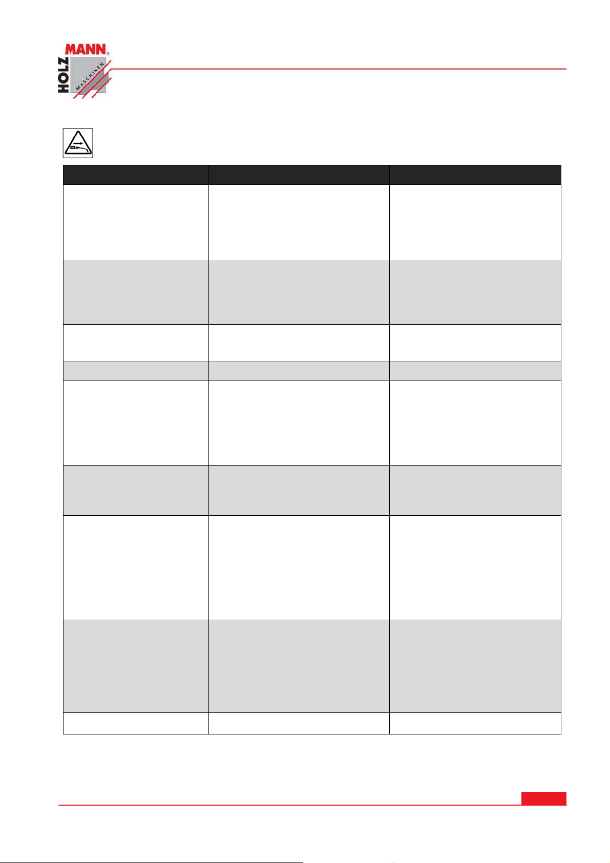
2 0 TROUBLE SHOOTI NG
Disconne ct t he mach ine from t he pow er supply prior to any check s perform ed
at the m a chine itse lf !
Trouble Possible Reason Solut ion
TROUBLE SH OOTI N G
Surface of workpiece too
rough
Tool blunt Resharpen tool
Tool springs Clamp tool with less overhang
Feed too high Reduce feed
Radius at the tool tip too small Increase radius
Workpiece becomes coned
Lathe is chattering
Centers runs hot Workpiece has expanded Loosen tailstock center
Tool has a short edge life
Flank wear too high
Centers are not aligned (tail-
Adjust tailstock to the center
stock has offset)
Top slide not aligned well (cut-
Align top slide well
ting with the top slide)
Feed too high Reduce feet
Slack in main bearing Adjust the main bearing
Cutting speed too high Reduce cutting speed
Cross feed too high Lower crossfeed (finishing al-
lowance should not exceed
0.5mm)
Insufficient cooling More coolant
Clearance angle too small Increase clearance angle
Tool tip not adjusted to center
high
Correct height adjustment of
the tool
Cutting edge breaks off
Wedge angle too small (heat
build-up)
Grinding crack due to wrong
cooling
Excessive slack in the spindle
bearing Arrangement (vibra-
Increase wedge angle
Cool uniformly
Adjust the slack in the spindle
bearing arrangement
tions)
Cut thread is wrong
Too is clamped incorrectly or has
been started grinding the wrong
way
Adjust to the center
Grind angle correctly
Wrong pitch Adjust the right pitch
Wrong diameter Turn the workpiece to the cor-
rect diameter
Spindle does not activate Emergency stop switch activated Unlock emergency stop switch
HOLZMANN Maschinen Austria www.holzmann-maschinen.at
Metalldrehmaschine / metal turning lathe ED 750 FDQ
Se it e 4 2
Page 43
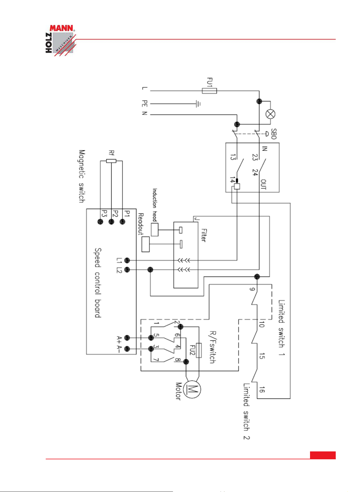
SCH ALTPLAN / CI RCUI T DI AGRAM
2 1 SCH ALTPLAN / CI RCUI T D I AGRAM
HOLZMANN Maschinen Austria www.holzmann-maschinen.at
Se it e 4 3
Metalldrehmaschine / metal turning lathe ED 750 FDQ
Page 44
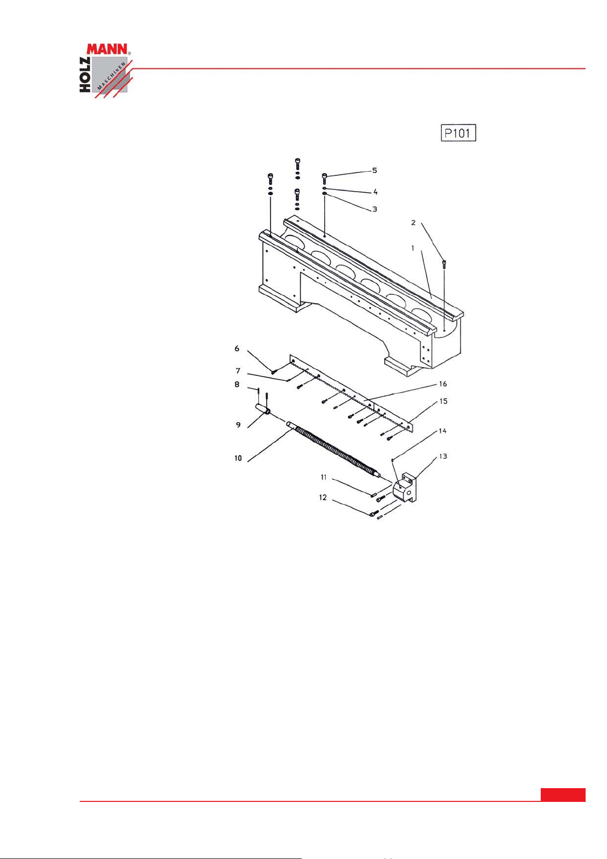
2 2 ERSATZTEI LE / SPARE PARTS
ERSATZTEI LE / SPARE PARTS
P10 1
1---------------P10101------------------------------------------------------------------------BED
2------------ GB10101----------------------------------------------------CAP SCREW M6x16
3------------GB10102----------------------------------------------------FLAT WASHER 8mm
4------------GB10103---------------------------------------------------LOCK WASHER 8mm
5------------GB10104-----------------------------------------------------CAP SCREW M8x25
6------------GB10105-----------------------------------------------------CAP SCREW M4x12
7------------GB10106----------------------------------------------------------------PIN 5x12
8------------GB10107----------------------------------------------------------------PIN 4x20
9--------------P10102---------------------------------------------------------------------COLLAR
10-------------P10103-------------------------------------------------------------FEED SCREW
11-----------GB10108--------------------------------------------------------PIN 6x25
12-----------GB10109-----------------------------------------------------CAP SCREW M6x16
13-------------P10104------------------------------------------------------------------BRACKET
14-----------GB10110----------------------------------------------------------------OIL PORT 6
15-------------P10105------------------------------------------------------------------------RACK
16-------------P10106------------------------------------------------------------------------RACK
HOLZMANN Maschinen Austria www.holzmann-maschinen.at
Metalldrehmaschine / metal turning lathe ED 750 FDQ
Se it e 4 4
Page 45
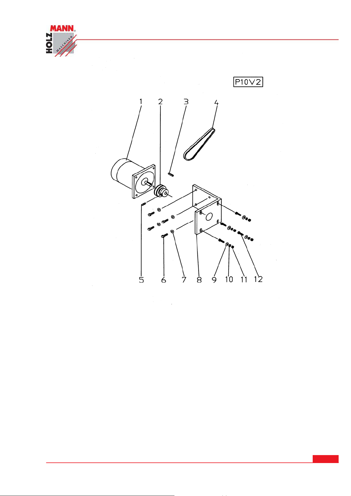
ERSATZTEI LE / SPARE PARTS
P1 0V2
1 ………………………P10V201 ….………………………………………………MOTOR
2 ……………………P10V202 …………………………………………………PULLEY
3 ……………………GB10V201 …………………………………................. KEY--C4X32
4 ……………………GB10V202 ………………….……………...…….. V-BELT—7M730
5 ……………………GB10V203 ………………….………………...SET SCREW—M5X8
6 ……………………GB10V204 ………………………….………CAP SCREW—M8X25
7 ……………………GB10V205 ……………………….…………………WASHER-8MM
8 ……………………P10V203 ……………………………………..…………BRACKET
9 ……………………GB10V206 ………………………………...………. WASHER-8MM
10 ……………………GB10V207 ……………………….…………LOCK WASHER-8MM
11 ……………………GB10V208 ……………………………………………HEX NUT-M8
12 …………………. GB10V209 ……………………………………CAP SCREW-M8X30
HOLZMANN Maschinen Austria www.holzmann-maschinen.at
Metalldrehmaschine / metal turning lathe ED 750 FDQ
Se it e 4 5
Page 46
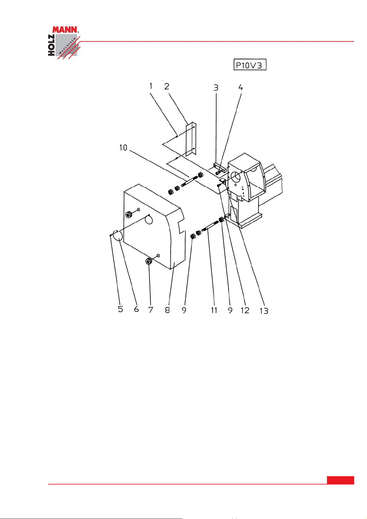
ERSATZTEI LE / SPARE PARTS
P1 0V3
1 ……………………GB10V301 ….……………………………….…CAP SCREW M4X6
2 ……………...………P10V301 ………………………………..…………………SHIELD
3 ………………...……P10V302 ……………………………………………..... SUPPORT
4 ……………………GB10V302 …………………………………..CAP SCREW M10X20
5 ……………………GB10V303 ………………….……...…………CAP SCREW M6X10
6 …………………...…P10V303 ……………………………………………..……COVER
7 ……………………...P10V304 ……………………………………...………………NUT
8 ………………………P10V305 …………………………………………..………COVER
9 ……………………GB10V304 …………...……………………...………. HEX NUT M8
10 ………………………P10V306 …………………………….………….…………SCREW
11 ………………………P10V307 ……………………………………..……………SCREW
12 …………………... GB10V305 ……………………………………CAP SCREW M6X12
13 ………………………P10V308 ………………………………………………...SUPPORT
HOLZMANN Maschinen Austria www.holzmann-maschinen.at
Metalldrehmaschine / metal turning lathe ED 750 FDQ
Se it e 4 6
Page 47
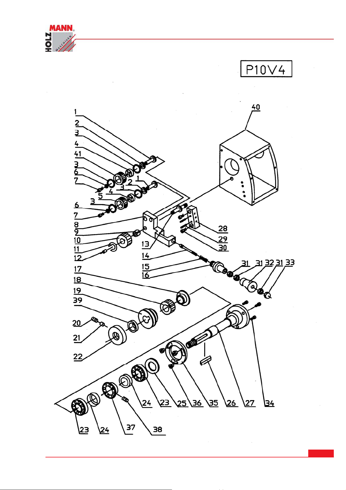
ERSATZTEI LE / SPARE PARTS
HOLZMANN Maschinen Austria www.holzmann-maschinen.at
Se it e 4 7
Metalldrehmaschine / metal turning lathe ED 750 FDQ
Page 48

ERSATZTEI LE / SPARE PARTS
P10 V4
1 ………………………P10V401 ….………………………..………………………SHAFT
2 ………………………P10V402 …………………………………………………WASHER
3 ………………………..10V401 ……………..……………….... INT RETAINING 22mm
4 ……………………GB10V402 ………………...….……………...…BEARING 1000900
5 ………………………P10V403 ……………………………....………………. GEAR 30T
6 ……………………GB10V403 …………...……………….………FLAT WASHER 6mm
7 ……………………GB10V404 ……………..………….……………CAP SCREW M6x8
8 ………………………P10V404 ………………………..……………………SHIFT ARM
9 ………………………P10V405 ……………………………………………...…BUSHING
10 ………………………P10V406 ………………….………………….………GEAR 40T
11 ……………………GB10V405 …………………….…………SPECIAL WASHER 9mm
12 ……………………GB10V406 …………………………….……………OIL PORT 6mm
13 ………………………P10V407 ….…………………………………………...……SHAFT
14 ………………………P10V408 ………….………………………………LOCATING PIN
15 ………………………P10V409 ……………………….……………………….... SPRING
16 ………………………P10V410 ………………….………………...………...…BUSHING
17 ………………………P10V411 ………………..……….………………. SPACING RING
18 ………………………P10V412 ……………………………..……….………GEAR 40T
19 ………………………P10V413 ……………………….…………………………PULLEY
20 ………………………..10V407 ……………………………………CAP SCREW M8x8
21 ………………………P104V14 …………………….………………………...…WASHER
22 ………………………P104V15 ………………………………….………SPANNER NUT
23 ……………………GB10V408 ………………………………………BEARING 2007107
24 ………………………P10V416 ………………………………...…………………COVER
25 ………………………P10V417 ….………………………………………………GASKET
26 ……………………GB10V409 …………………….………………………KEY A4x50
27 ………………………P10V418 …………………….…………..…………….... SPINDLE
28 ………………………P10V419 ………………….…..…………...…LOCATING BLOCK
29 ………………………..B10410 ………………….………………………..…. PIN 3x20
30 ………………………GB10411 …………………………..………CAP SCREW M6x16
31 ………………………GB10412 ……………………….…………………HEX NUT M6
32 ………………………P10V420 ……………………..…………….….…………HANDLE
33 ……………………GB10V413 ………………………...……………...…CAP NUT M6
34 ……………………GB10V414 ……………………….….………CAP SCREW M6x12
35 ………………………P10V421 …………………………………………………WASHER
36 ………………………P10V422 ……………………..……………LOCATING BUSHING
37 ………………………P10V423 ….…………………………………….……………RING
38 ………………………P10V415 ………………………..……………SET SCREW M4X8
HOLZMANN Maschinen Austria www.holzmann-maschinen.at
Metalldrehmaschine / metal turning lathe ED 750 FDQ
Se it e 4 8
Page 49
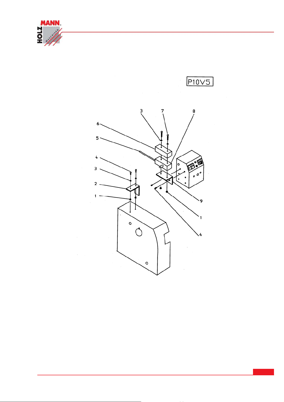
ERSATZTEI LE / SPARE PARTS
39 ………………………P10V424 ……………………………………….... SPACING RING
40 ………………………P10V425 …………………………......…HEADSTOCK CASTING
41…………………………P10V426……………………………………………………………………..GEAR 40T
P10 V5
1 ………………………GB10501 …………………………………………HEX NUT M4
2 ………………...………P10501 ………………… … … . …………………… … B RACKET
3 ………………………GB10502 ……………………….……….. FLAT WASHER 4mm
4 ………………………GB10503 …………………………….………….. SCREW M4x8
5 ………………………GB10504 …………………………………………CABLE 2x0.75
6 ………………………GB10505 ……………………………………..…SWITCH COVER
7 ………………………GB10506 ……………..…………………………SCREW M4x30
8 ………………………GB10507 …………………………………SWITCH LXW5-11D1
9 …………...……………P10502 ………………… … … … .………………… … B RACKET
HOLZMANN Maschinen Austria www.holzmann-maschinen.at
Metalldrehmaschine / metal turning lathe ED 750 FDQ
Se it e 4 9
Page 50
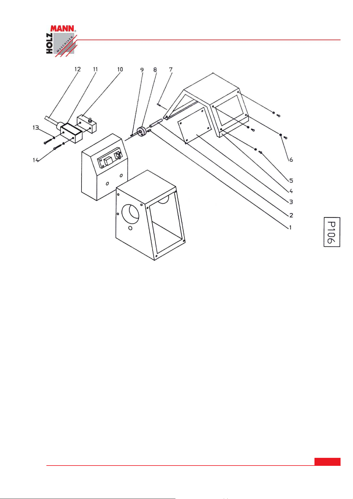
ERSATZTEI LE / SPARE PARTS
P10 6
1-------------- -GB10601--------------------------------------------------------PIN 5x12
2----------------P10601---------------------------------------------------------------SHAFT
3----------------P10602---------------------------------------------------------------COVER
4----------------P10603---------------------------------------------------------------COVER
5----------------GB10602--------------------------------------------------SCREW M3x8
6----------------GB10603--------------------------------------------------HEX NUT M3
7----------------GB10604--------------------------------------------------------PIN 4x16
8----------------P10604------------------------------------------------------------------CAM
9----------------GB10605--------------------------------------------------SCREW M4x6
10---------------GB10606----------------------------------------SWITCH LXW5-11D1
11---------------GB10607-------------------------------------------------------------COVER
12---------------GB10608--------------------------------------------------CABLE 2x0.75
13---------------GB10609------------------------------------------FLAT WASHER 4mm
14---------------GB10610--------------------------------------------------SCREW M4x25
HOLZMANN Maschinen Austria www.holzmann-maschinen.at
Metalldrehmaschine / metal turning lathe ED 750 FDQ
Se it e 5 0
Page 51
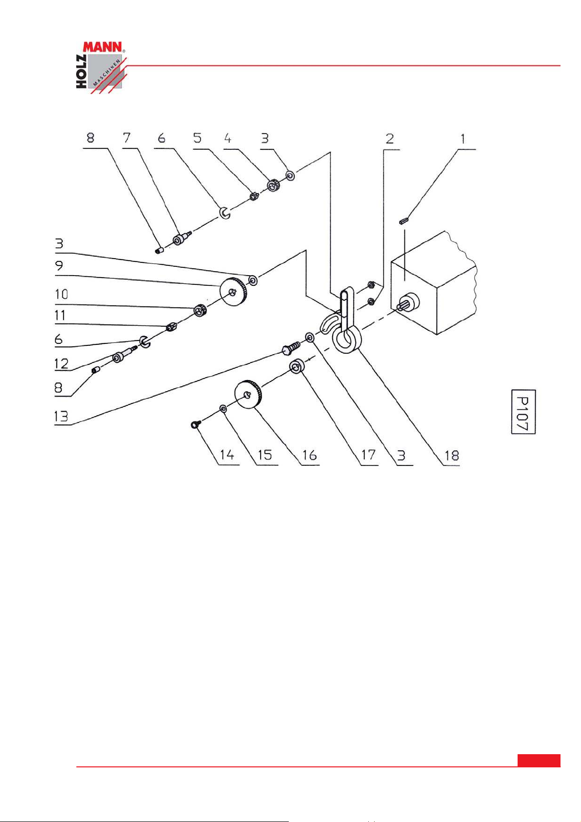
ERSATZTEI LE / SPARE PARTS
1----------------GB10701----------------------------------------------------------------KEY C5x14
2----------------GB10702-------------------------------------------------------------HEX NUT M8
3----------------P10701---------------------------------------------------------------------WASHER
4----------------P10702------------------------------------------------------------------GEAR 30T
5----------------P10703--------------------------------------------------------------------BUSHING
6----------------P10704----------------------------------------------------------SPECIAL WASHER
7----------------P10705-----------------------------------------------------------------------SHAFT
8----------------GB10703-----------------------------------------------------------OIL PORT 6mm
9----------------P10706-----------------------------------------------------------------GEAR 100T
10--------------P10707-------------------------------------------------------------------GEAR 30T
11--------------P10708--------------------------------------------------------------------BUSHING
12--------------P10709------------------------------------------------------------------------SHAFT
13--------------GB10704--------------------------------------------------------HEX BOLT M8x20
14--------------GB10705------------------------------------------------------CAP SCREW M5x16
15--------------P10710---------------------------------------------------------------------WASHER
16--------------P10711-------------------------------------------------------------------GEAR 96T
17--------------P10712--------------------------------------------------------------SPACING RING
18--------------P10713---------------------------------------------------------------------BRACKET
HOLZMANN Maschinen Austria www.holzmann-maschinen.at
Metalldrehmaschine / metal turning lathe ED 750 FDQ
Se it e 5 1
Page 52
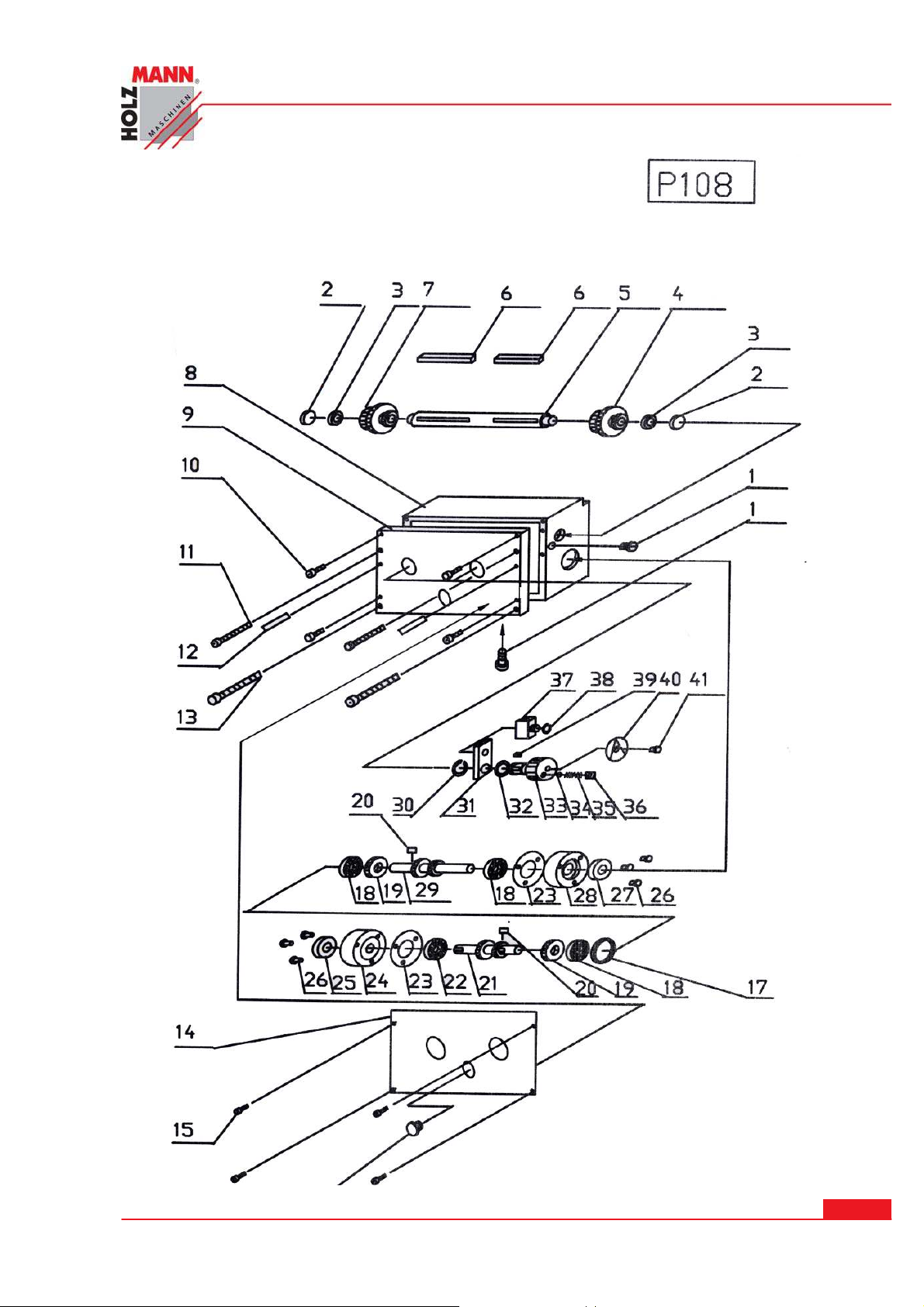
ERSATZTEI LE / SPARE PARTS
HOLZMANN Maschinen Austria www.holzmann-maschinen.at
Se it e 5 2
Metalldrehmaschine / metal turning lathe ED 750 FDQ
Page 53

ERSATZTEI LE / SPARE PARTS
P10 8
1----------------GB10801-------------------------------------------------------BOLT M10x1x10
2----------------P10801------------------------------------------------------------------------PLUG
3----------------GB10802----------------------------------------------------BEARING 1000802
4----------------P10802------------------------------------------------------------------------GEAR
5----------------P10803-----------------------------------------------------------------------SHAFT
6----------------GB10803---------------------------------------------------------------KEY A4x55
7----------------P10804------------------------------------------------------------------------GEAR
8----------------P10805-------------------------------------------------------------------GEAR BOX
9----------------P10806-----------------------------------------------------------------------COVER
10---------------GB10804---------------------------------------------------CAP SCREW M5x20
11---------------GB10805---------------------------------------------------CAP SCREW M6x90
12---------------GB10806-----------------------------------------------------------------PIN 3x20
13---------------GB10807----------------------------------------------------CAP SCREW M8x90
14---------------P10807-----------------------------------------------------------------------PLATE
15---------------GB10808----------------------------------------------------------- -SCREW M3X6
16---------------GB10809---------------------------------------------------SIGHT GLASS 20mm
17---------------P10808-------------------------------------------------------------SPACING RING
18---------------GB10810------------------------------------------------------------BEARING 202
19---------------P10809------------------------------------------------------------------GEAR 25T
20---------------GB10811-----------------------------------------------------------------KEY A4x8
21---------------P10810-----------------------------------------------------------------------SHAFT
22---------------GB10812------------------------------------------------------------BEARING 103
23---------------P10811------------------------------------------------------------PAPER WASHER
24---------------P10812---------------------------------------------------------------------FLANGE
25---------------GB10813-----------------------------------------------------OIL SEAL 17x30x10
26---------------GB10814-----------------------------------------------------CAP SCREW M5x20
27---------------GB10815-----------------------------------------------------OIL SEAL 15x30x10
28---------------P10813---------------------------------------------------------------------FLANGE
29---------------P10814----------------------------------------------------------------GEAR SHAFT
30---------------GB10816------------------------------------------EXT RETAINING RING 12mm
31---------------P10815---------------------------------------------------------------SHIFT LEVER
32---------------GB10817------------------------------------------------------------O-RING 9x1.8
33---------------P10816---------------------------------------------------------------------HANDLE
34---------------GB10818---------------------------------------------------------------STEEL BALL
35---------------P10817---------------------------------------------------------------------SPRING
36---------------GB10819------------------------------------------------------------SCREW M6x6
37---------------P10818------------------------------------------------------------------------FORK
38---------------GB10820-----------------------------------------EXT RETAINING RING 10mm
39---------------GB10821-----------------------------------------------------------------KEY B4x6
40---------------P10819-----------------------------------------------------------INDICATOR DISK
41---------------GB10822------------------------------------------------------------SCREW M4x8
HOLZMANN Maschinen Austria www.holzmann-maschinen.at
Se it e 5 3
Metalldrehmaschine / metal turning lathe ED 750 FDQ
Page 54
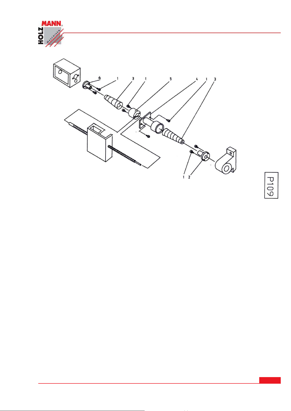
ERSATZTEI LE / SPARE PARTS
P10 9
1----------------GB10901-----------------------------------------------------------SCREW M4x10
2----------------P10901--------------------------------------------------------------------BRACKET
3----------------P10902--------------------------------------------------------------SCREW COVER
4----------------P10903--------------------------------------------------------------------BRACKET
5----------------P10904--------------------------------------------------------------------BRACKET
6----------------P10905--------------------------------------------------------------------BRACKET
HOLZMANN Maschinen Austria www.holzmann-maschinen.at
Se it e 5 4
Metalldrehmaschine / metal turning lathe ED 750 FDQ
Page 55
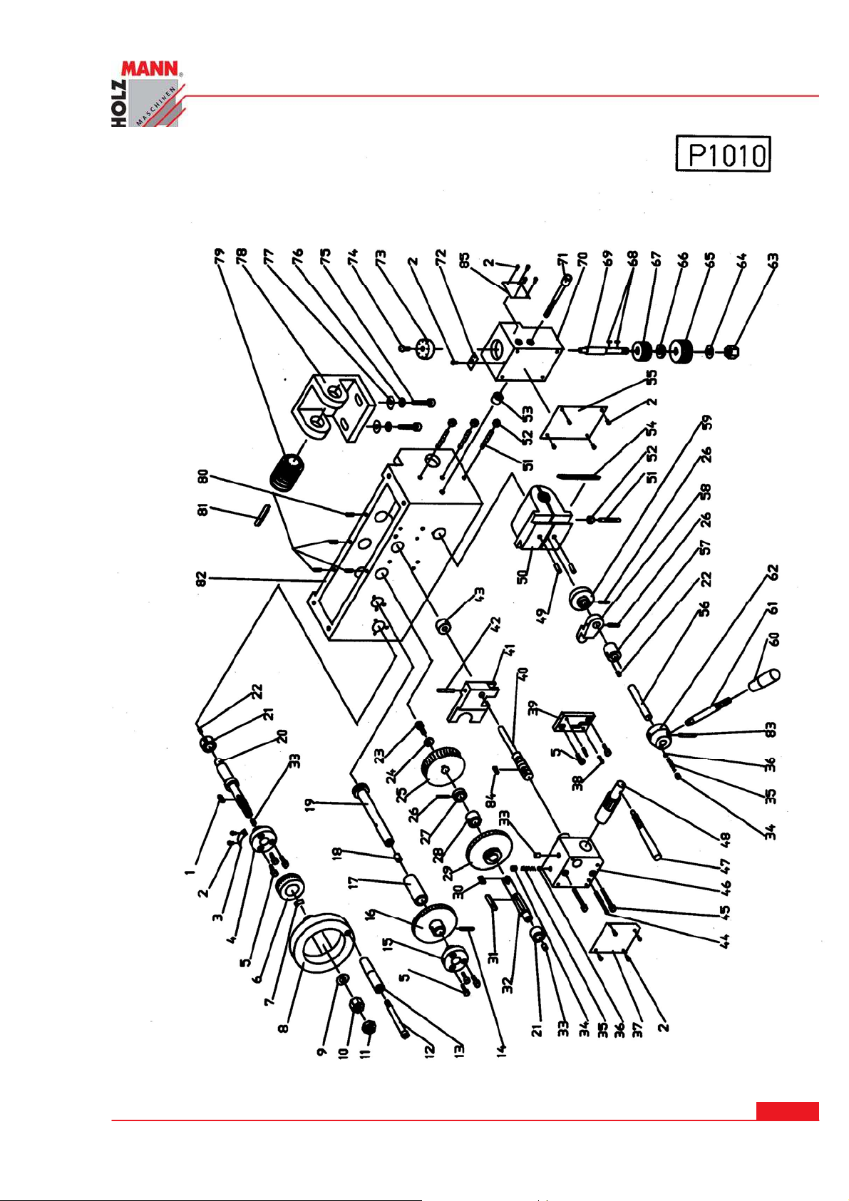
ERSATZTEI LE / SPARE PARTS
HOLZMANN Maschinen Austria www.holzmann-maschinen.at
Se it e 5 5
Metalldrehmaschine / metal turning lathe ED 750 FDQ
Page 56

ERSATZTEI LE / SPARE PARTS
P10 1 0
1..……..….GB101001……………………………..………………………………KEY A4x14
2..……..….GB101002……………………………..……………………………….RIVET 2x4
3..……..….P101001………………………………..……………………………………..PLATE
4..……..….P101002………………………………...…………………………………..FLANGE
5..……..….GB101003………………………………...…………………CAP SCREW M4x10
6..…..…….P101003…………………………………….…………………GRADUATED DIAL
7..…..…….P101004……………………………………..……………………………..CURSOR
8..…..…….P101005…………………………………….……………………….HAND WHEEL
9..…..…….GB101004…………………………………………………FLAT WASHER 10mm
10..……….GB101005…………………………………………………………HEX NUT M10
11..……….GB101006…………………………………………………………HEX NUT M10
12..……….P101006…………………………………………………………HANDLE SCREW
13..……….P101007……………………………………………………………………HANDLE
14..……….GB101007…………………………………………………...……………PIN 4x20
15..……….P101008………………………………………………………………….…FLANGE
16..……….P101009……………...…………………………………………………GEAR 70T
17..……….P101010………………….…………………………………………SPACING RING
18..……….GB101008…………………………………………………………OIL PORT 8mm
19..……….P101011………………………………………………………………GEAR SHAFT
20..……….P101012………………………………………………………………GEAR SHAFT
21..……….P101013…………………………………...………………………………BUSHING
22..……….GB101009…………………………………..………………………SCREW M4x6
23..……….GB101010…………………………………...………………CAP SCREW M5x12
24..……….GB101011…………………………………….…………BIG FLAT WASHER 5mm
25..……….P101014………………………………………………...………………GEAR 30T
26..……….GB101012………………...………………………………………………PIN 3x18
27..……….P101015…………………….………………………………………SPACING RING
28..……….P101016……………………………..……………………………………BUSHING
29--------P101017……………………………………………………………………GEAR
30..……….GB101013………………………………………..……………………KEY C4x10
31..……….GB101014…………………………………………..…………………KEY A5x30
32..……….P101018………………………………………………………………………SHAFT
33..……….GB101015…………………………………………………………OIL PORT 6mm
34..……….GB101016……………………..……………………………………SCREW M6x6
35..……….P101019……………………......……………………………………………SPRING
36..……….GB101017………………….…………………………………STEEL BALL 5mm
37..……….P101020………………………………………………………………………PLATE
38..……….GB101018……………………………………..…………………………PIN 3x12
39..……….P101021…………………………………….…………………LOCATING BLOCK
40..……….P101022………………………………………………………………………SHAFT
41..……….P101023………………………………………………………………..………FORK
42..……….GB101019………………….………………………………………………PIN 3x26
43..……….P101024…………………………...………………………………………BUSHING
44..……….GB101020…………...……………………………………………………PIN 3x35
45..……….GB101021……...……………………………………………CAP SCREW M4x35
46..……….P101025…………………………………………………………………-BRACKET
HOLZMANN Maschinen Austria www.holzmann-maschinen.at
Metalldrehmaschine / metal turning lathe ED 750 FDQ
Se it e 5 6
Page 57

ERSATZTEI LE / SPARE PARTS
47..……….P101026……………………………………………………………………HANDLE
48..……….P101027………………………………………………………………GEAR SHAFT
49..……….GB101022…………………………………..……………………………PIN 5x12
50..……….P101028…………………………………………………………………HALF NUT
51..……….GB101023…………………………………………………………SCREW M5x30
52..……….GB101024…………………………………………..………………HEX NUT M5
53..……….P101029……………………………………………………………………WASHER
54..……….P101030…………………….……………………………………………………GIB
55..……….P101031………………………………………………………………………PLATE
56..……….P101032………………………………………………………………………SHAFT
57..……….P101033………………………………………………………...…………BUSHING
58..……….P101034…..……………………………………………………LOCATING BLOCK
59..……….P101035……………………………………………………………LOCKING CAM
60..……….P101036……..……………………………………………………LEVER HANDLE
61..……….P101037………………………………………………………………………LEVER
62..……….P101038…………………...…………………………………………LEVER HAND
63..……….GB101025…………………..………………………………………HEX NUT M8
64..……….GB101026…………………..………………………………………FLAT WASHER
65..……….P101039…………………………...……………………………………GEAR 45T
66..……….P101040……………………………………………………………………WASHER
67..……….P101041……………………………………………...…………………GEAR 42T
68..……….GB101027………………………………………………………………KEY A3x8
69..……….P101042………………………………………………………………………SHAFT
70..……….P101043………………..…………………………………………………BRACKET
71..……….GB101028…………..…………………………………………CAP SCREW M6x60
72..……….P101044…………………………...……………………………………………PLAT
73..……….P101045………………………………………….…………………………….DIAL
74..……….GB101029………….………………………………………………SCREW M4x8
75..……….GB101030…..………………………………………………CAP SCREW M6x25
76..……….GB101031…………………………………………………………WASHER 6mm
77..……….GB101032……………………………………………………BIG WASHER 6mm
78..……….P101046……………………………………………………………………BRACKET
79..……….P101047………………………………………………………………………WORM
80..……….GB101033…………………………………………………………..SCREW M4x8
81..……….GB101034……………………………………………………………..KEY A5x35
82..……….P101048………………………………………………………….APRON CASTING
83..……….GB101035………………………………………………………………..PIN 3X30
84..……….GB101036…………………………………………………………….KEY A4X12
85..……….P101049………………………………………………………………………PLATE
HOLZMANN Maschinen Austria www.holzmann-maschinen.at
Se it e 5 7
Metalldrehmaschine / metal turning lathe ED 750 FDQ
Page 58
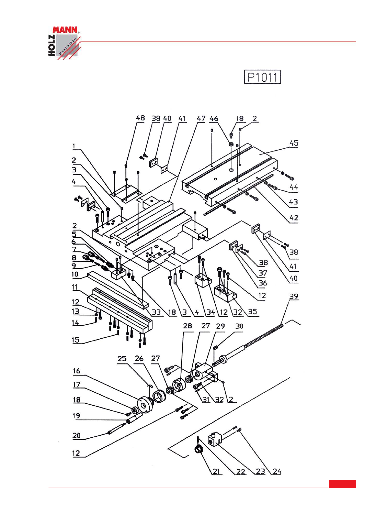
ERSATZTEI LE / SPARE PARTS
HOLZMANN Maschinen Austria www.holzmann-maschinen.at
Se it e 5 8
Metalldrehmaschine / metal turning lathe ED 750 FDQ
Page 59

ERSATZTEI LE / SPARE PARTS
P10 1 1
1----------------P101101---------------------------------------------------------------------COVER
2----------------GB101101---------------------------------------------------------OIL PORT 6mm
3----------------GB101102---------------------------------------------------CAP SCREW M6x35
4----------------GB101103----------------------------------------------------------------PIN 6x35
5----------------P101102---------------------------------------------------------------------NIPPER
6----------------P101103------------------------------------------------------------------------PIPE
7----------------P101104---------------------------------------------------------------NIPPER NUT
8----------------P101105-------------------------------------------------------------PIPE BUSHING
9----------------P101106------------------------------------------------------------------------PIPE
10---------------P101107------------------------------------------------------------------------GIB
11---------------P101108----------------------------------------------------APRON TENSION BAR
12---------------GB101104---------------------------------------------------CAP SCREW M5x20
13---------------GB101105------------------------------------------------------------HEX NUT M4
14---------------GB101106-----------------------------------------------------SET SCREW M4x16
15---------------GB101107-----------------------------------------------------SET SCREW M4x20
16---------------P101109-------------------------------------------------------------HAND WHEEL
17---------------P101110-------------------------------------------------------------------WASHER
18---------------GB101108----------------------------------------------------CAP SCREW M5x10
19---------------P101111------------------------------------------------------------------HANDLE
20---------------P101112--------------------------------------------------------------------SCREW
21---------------P101113-----------------------------------------------------------------GEAR 18T
22---------------GB101109----------------------------------------------------------------PIN 4x20
23---------------P101114------------------------------------------------------------------------NUT
24---------------GB101110-------------------------------------------------------------SET SCREW
25---------------P101115--------------------------------------------------------------------SPRING
26---------------P101116--------------------------------------------------------GRADUATED DIAL
27---------------GB101111-----------------------------------------------------BEARING 12x26x9
28---------------P101117------------------------------------------------------------------BRACKET
29---------------P101118------------------------------------------------------------------BRACKET
30---------------GB101112---------------------------------------------------------------KEY A4x8
31---------------GB101113----------------------------------------------------------------PIN 3x16
32---------------GB101114---------------------------------------------------CAP SCREW M8x20
33---------------P101119------------------------------------------------------------------BRACKET
34---------------P101120-------------------------------------------------------------SLIDE BLOCK
35---------------P101121---------------------------------------------------------------BRAKE CLIP
36---------------P101122---------------------------------------------------------------WAY WIPER
37---------------P101123---------------------------------------------------------------------COVER
38---------------GB101115---------------------------------------------------CAP SCREW M3x10
39---------------P101124--------------------------------------------------------------LEAD SCREW
40---------------P101125---------------------------------------------------------------WAY WIPER
41---------------P101126---------------------------------------------------------------------COVER
HOLZMANN Maschinen Austria www.holzmann-maschinen.at
Se it e 5 9
Metalldrehmaschine / metal turning lathe ED 750 FDQ
Page 60
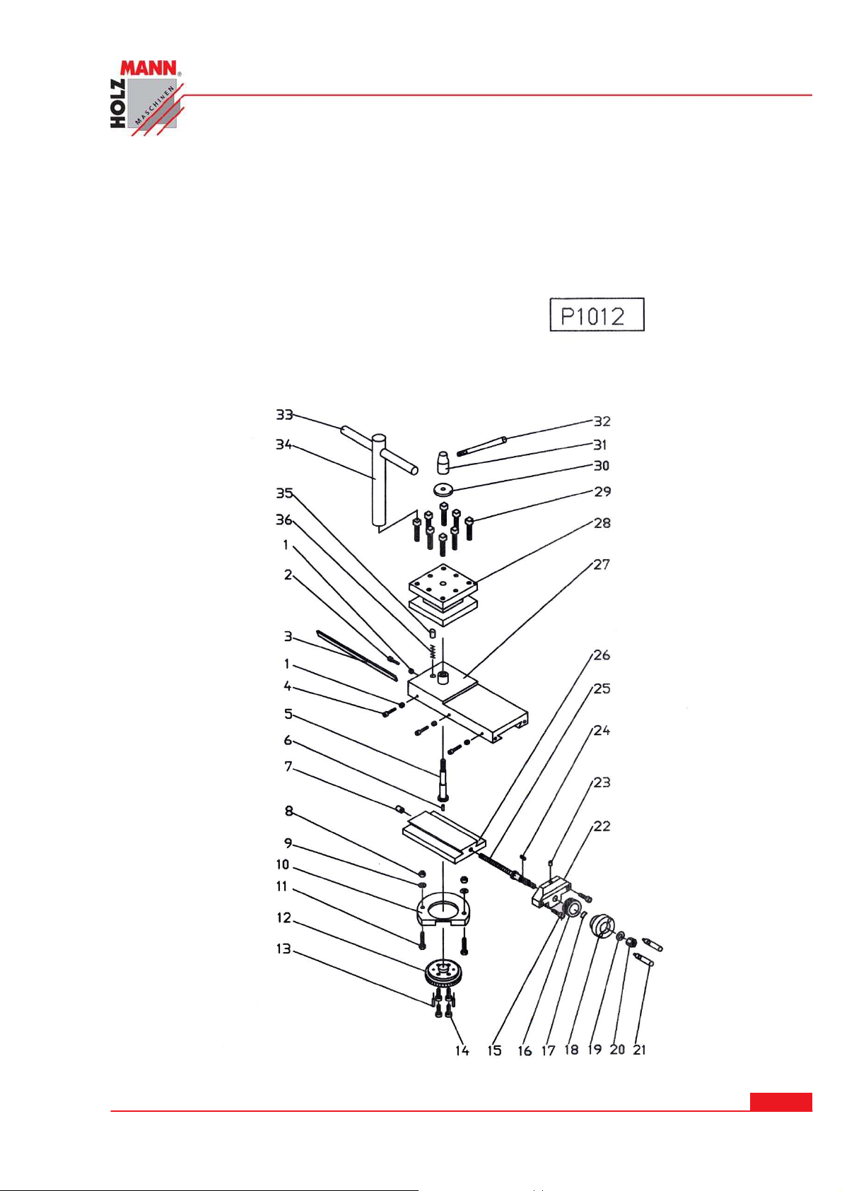
ERSATZTEI LE / SPARE PARTS
42---------------P101127------------------------------------------------------------------------GIB
43---------------GB101116-----------------------------------------------------------HEX NUT M5
44---------------GB101117-----------------------------------------------------SET SCREW M5x25
45---------------P101128-------------------------------------------------------------CROSS SLIDE
46---------------P101129-----------------------------------------------------------------WASHER
47---------------P101130-------------------------------------------------------------------SADDLE
48---------------GB101118------------------------------------------------------CAP SCREW M3x6
HOLZMANN Maschinen Austria www.holzmann-maschinen.at
Se it e 6 0
Metalldrehmaschine / metal turning lathe ED 750 FDQ
Page 61

ERSATZTEI LE / SPARE PARTS
P10 1 2
1----------------GB101201------------------------------------------------------------HEX NUT M4
2----------------GB101202-----------------------------------------------------CAP SCREW M4x12
3----------------P101201-------------------------------------------------------------------------GIB
4----------------GB101203---------------------------------------------------CAP SCREW M4x20
5----------------P101202---------------------------------------------------------------------SCREW
6----------------GB101204----------------------------------------------------------------PIN 3x10
7----------------GB101205--------------------------------------------------------OIL PORT 10mm
8----------------GB101206------------------------------------------------------------HEX NUT M6
9----------------GB101207----------------------------------------------------FLAT WASHER 6mm
10---------------P101203---------------------------------------------------------------------COVER
11---------------GB101208----------------------------------------------------HEX SCREW M6x25
12---------------P101204--------------------------------------------------------GRADUATED DIAL
13---------------GB101209----------------------------------------------------------------PIN 4x16
14---------------GB101210----------------------------------------------------CAP SCREW M6x16
15---------------GB101211----------------------------------------------------CAP SCREW M5x16
16---------------P101205--------------------------------------------------------GRADUATED DIAL
17---------------P101206--------------------------------------------------------------------SPRING
18---------------P101207-------------------------------------------------------------HAND WHEEL
19---------------GB101212---------------------------------------------------FLAT WASHER 8mm
20---------------GB101213------------------------------------------------------------HEX NUT M8
21---------------P101208-------------------------------------------------------------------HANDLE
22---------------P101209-----------------------------------------------------LEAD SCREW MOUNT
23---------------GB101214---------------------------------------------------------OIL PORT 6mm
24---------------GB101215-------------------------------------------------------------KEY A3x10
25---------------P101210--------------------------------------------------------------LEAD SCREW
26---------------P101211-------------------------------------------------------------SWIVEL BASE
27---------------P101212--------------------------------------------------------COMPOUND SLIDE
28---------------P101213----------------------------------------------------------------TOOL REST
29---------------GB101216---------------------------------------------------SET SCREW M8x30
30---------------P101214-------------------------------------------------------------------WASHER
31---------------P101215-----------------------------------------------------------------LOCK NUT
32---------------P101216-------------------------------------------------------------------HANDLE
33---------------P101217-------------------------------------------------------------------HANDLE
34---------------P101218------------------------------------------------------------------------KEY
35---------------P101219-------------------------------------------------------------------------PIN
36---------------GB101217-------------------------------------------------- -SPRING 0.5x3.5x17
HOLZMANN Maschinen Austria www.holzmann-maschinen.at
Se it e 6 1
Metalldrehmaschine / metal turning lathe ED 750 FDQ
Page 62

ERSATZTEI LE / SPARE PARTS
HOLZMANN Maschinen Austria www.holzmann-maschinen.at
Metalldrehmaschine / metal turning lathe ED 750 FDQ
Se it e 6 2
Page 63

ERSATZTEI LE / SPARE PARTS
P10 1 3
1----------------P101301-------------------------------------------------------------------HANDLE
2----------------P101302-----------------------------------------------------------HANDLE SCREW
3----------------GB101301------------------------------------------------------------HEX NUT M8
4----------------GB101302--------------------------------------------------FLAT WASHER 8mm
5----------------P101303-------------------------------------------------------------------SPRING
6----------------P101304---------------------------------------------------------GRADUATED DIAL
7----------------GB101303----------------------------------------------------CAP SCREW M5x25
8----------------P101305----------------------------------------------------------------END COVER
9----------------P101306----------------------------------------------------------------------PLATE
10---------------GB101304--------------------------------------------------------OIL PORT 6mm
11---------------GB101305-------------------------------------------------------------KEY C4x15
12---------------P101307--------------------------------------------------------------LEAD SCREW
13---------------P101308--------------------------------------------------------CLAMPING SCREW
14---------------P101309-------------------------------------------------------------------HANDLE
15---------------GB101306--------------------------------------------------FLAT WASHER 8mm
16---------------P101310---------------------------------------------------------------------CLAMP
17---------------P101311---------------------------------------------------------------------CLAMP
18---------------P101312------------------------------------------------------------------------KEY
19---------------P101313---------------------------------------------------------TALL STOCK RAM
20---------------P101314-------------------------------------------------------TALL STOCK BODY
21---------------P101315---------------------------------------------------------------------COVER
22---------------GB101307------------------------------------------------------CAP SCREW M4x5
23---------------GB101308---------------------------------------------------------SCREW M6x16
24---------------P101316--------------------------------------------------------TALL STOCK BASE
25---------------GB101309---------------------------------------------------CAP SCREW M8x30
26---------------P101317-------------------------------------------------------------------HEX NUT
27---------------P101318--------------------------------------------------------------------SCREW
28---------------P101319---------------------------------------------------------CLAMPING PLATE
29---------------GB101310----------------------------------------------------------HEX NUT M12
30---------------P101320----------------------------------------------------------------------PLATE
31---------------GB101311--------------------------------------------------------------RIVET 2x4
32---------------P101321----------------------------------------------------------------------PLATE
33---------------GB101312----------------------------------------------------------------PIN 4x30
34---------------P101322---------------------------------------------------------------------SHAFT
35---------------P101323-------------------------------------------------------------------HANDLE
36---------------P101324-------------------------------------------------------------------------PIN
37---------------P101325-------------------------------------------------------------HAND WHEEL
HOLZMANN Maschinen Austria www.holzmann-maschinen.at
Se it e 6 3
Metalldrehmaschine / metal turning lathe ED 750 FDQ
Page 64
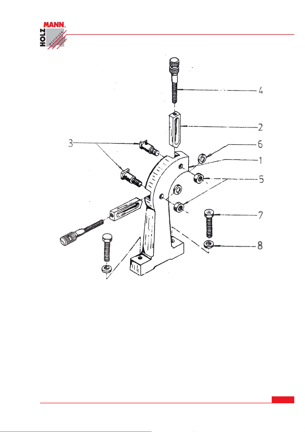
ERSATZTEI LE / SPARE PARTS
P10 1 4
1----------------P101401------------------------------------------------------------REST CASTING
2----------------P101402-----------------------------------------------------------------------JAW
3----------------P101403----------------------------------------------------------SPECIAL SCREW
4----------------P101404------------------------------------------------------ADJUSTING SCREW
5----------------GB101401---------------------------------------------------------HEX NUT M10
6----------------GB101402------------------------------------------------FLAT WASHER 10mm
7----------------GB101403--------------------------------------------------CAP SCREW M8x30
8----------------GB101404-------------------------------------------------FLAT WASHER 8mm
P1015
HOLZMANN Maschinen Austria www.holzmann-maschinen.at
Metalldrehmaschine / metal turning lathe ED 750 FDQ
Se it e 6 4
Page 65
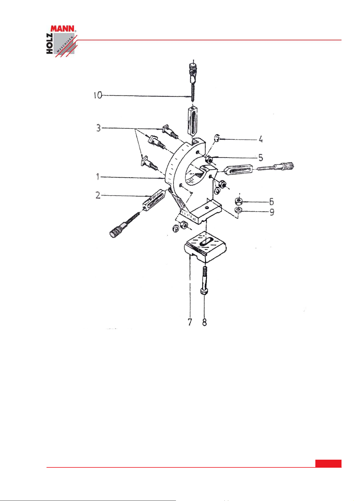
ERSATZTEI LE / SPARE PARTS
1----------------P101501------------------------------------------------------------REST CASTING
2----------------P101502------------------------------------------------------------------------JAW
3----------------P101503----------------------------------------------------------SPECIAL SCREW
4----------------GB101501--------------------------------------------------FLAT WASHER 10mm
5----------------GB101502-----------------------------------------------------------HEX NUT M10
6----------------GB101503-----------------------------------------------------------HEX NUT M12
7----------------P101504----------------------------------------------------------CLAMPING PLATE
8----------------GB101504------------------------------------------------------HEX BOLT M12x70
9----------------GB101505---------------------------------------------------FLAT WASHER 12mm
10---------------P101505-------------------------------------------------------ADJUSTING SCREW
HOLZMANN Maschinen Austria www.holzmann-maschinen.at
Metalldrehmaschine / metal turning lathe ED 750 FDQ
Se it e 6 5
Page 66
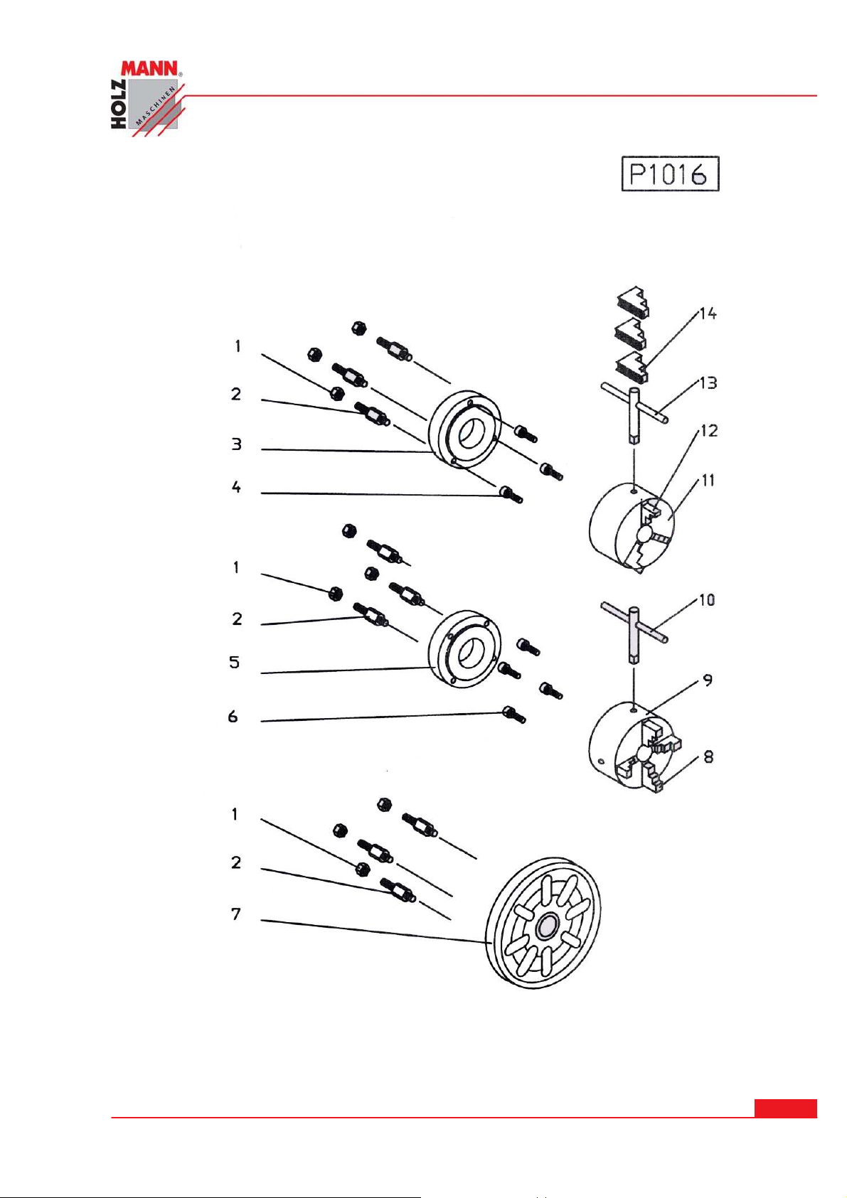
ERSATZTEI LE / SPARE PARTS
HOLZMANN Maschinen Austria www.holzmann-maschinen.at
Se it e 6 6
Metalldrehmaschine / metal turning lathe ED 750 FDQ
Page 67
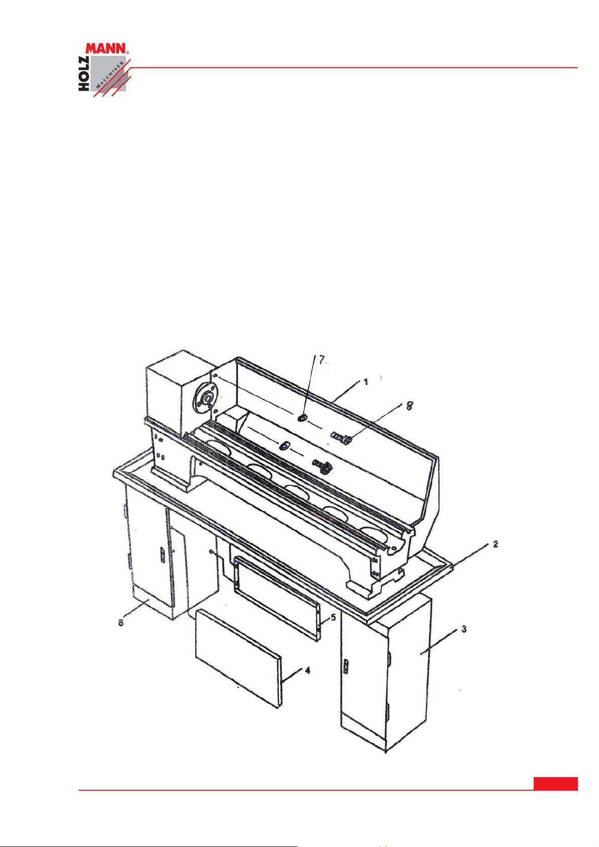
ERSATZTEI LE / SPARE PARTS
P10 1 6
1----------------GB101601---------------------------------------------------------HEX NUT M10
2----------------P101601---------------------------------------------------------------------SCREW
3----------------P101602--------------------------------------------BACK PLATE FOR 3-JAW125
4----------------GB101602---------------------------------------------------HEX SCREW M8x25
5----------------P101603---------------------------------------------BACK PLATE FOR 4-JAW125
6----------------GB101603----------------------------------------------------CAP SCREW M8x20
7----------------P101604---------------------------------------------------------------FACE PLATE
8----------------GB101604----------------------------------------------------------------------JAW
9----------------GB101605--------------------------------------------------------------------PLATE
10---------------GB101606--------------------------------------------------CHUCK KEY-4JAW125
11---------------GB101607--------------------------------------------------------------------PLATE
12---------------GB101608-----------------------------------------------------------REVERSE JAW
13---------------GB101609--------------------------------------------------CHUCK KEY-3JAW125
14---------------GB101610----------------------------------------------------------------------JAW
HOLZMANN Maschinen Austria www.holzmann-maschinen.at
Se it e 6 7
Metalldrehmaschine / metal turning lathe ED 750 FDQ
Page 68

ERSATZTEI LE / SPARE PARTS
P10 1 7
1----------------P101701-------------------------------------------------------------CHIP SHIELD
2----------------P101702-------------------------------------------------------------------CHP PAN
3----------------P101703---------------------------------------------RIGHT MOUNTING FEEL
4----------------P101704-----------------------------------------------------------FRONT PLATE
5----------------P101705-----------------------------------------------------CONNECTED PLAT
6----------------P101706-----------------------------------------------LEFT MOUNTING FEEL
7----------------GB101701-----------------------------------------------FLAT WASHER 6mm
8----------------GB101702-------------------------------------------------CAP SCREW M6x8
9----------------GB101703-----------------------------------------------HEX SCREW M8x20
10---------------GB101704---------------------------------------------HEX SCREW M12x30
11---------------GB101705--------------------------------------------------------HEX NUT M8
12---------------GB101706-----------------------------------------------FLAT WASHER 8mm
13---------------GB101707----------------------------------------------FLAT WASHER 12mm
5 0
HOLZMANN Maschinen Austria www.holzmann-maschinen.at
Se it e 6 8
Metalldrehmaschine / metal turning lathe ED 750 FDQ
Page 69
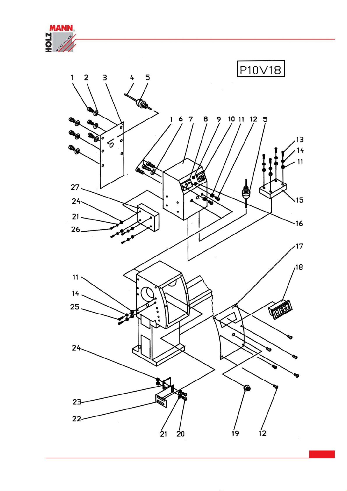
ERSATZTEI LE / SPARE PARTS
HOLZMANN Maschinen Austria www.holzmann-maschinen.at
Se it e 6 9
Metalldrehmaschine / metal turning lathe ED 750 FDQ
Page 70

ERSATZTEI LE / SPARE PARTS
P10 V1 8
1..……….GB10V1801……………………………………………………..CAP SCREW M5X8
2..……….GB10V1802………………………………………………………………WASHER 5
3..……….P10V1801…………………………………………………………………….COVER
4..……….GB10V1803…………………………………………………………………...CABLE
5..……….GB10V1804………………………………………………………………………NUT
6..……….GB10V1805……………………………………………………………….WASHER 5
7..……….P10V1802…………………………………………………………………..HOUSING
8..……….GB10V1806………………………………………………………….SWITCH KJD17
9..……….GB10V1807……………………………………………………………………LIGHT
10..……...GB10V1808…………………………………………………………..SWITCH ZH-A
11..……...GB10V1809…………………………………………………………HEX NUT M4
12..……...GB10V1810……………………………………………………..CAP SCREW M4X8
13..……...GB10V1811……………………………………………………CAP SCREW M4X12
14..……...GB10V1812……………………………………………………………….WASHER 4
15..……...GB10V1813…………………………………………………….CIRCUITIY BOARD
16..……...GB10V1814………………………………………………………………..FUSH 10A
17..……...P10V1803………………………………………………………………………PLATE
18..……...GB10V1815……………………………………………………………SPEED GAGE
19..……...GB10V1816…………………………………………………….SPEED GOVERNOR
20..……...GB10V1817……………………………………………………..CAP SCREW M3X8
21..……...GB10V1818……………………………………………………………….WASHER 3
22..……...P10V1804…………………………………………………………………..SUPPORT
23..……...GB10V1819………………………………………………………………INDUCTOR
24..……...GB10V1820……………………………………………………………HEX NUT M3
25..……...GB10V1821……………………………………………………CAP SCREW M4X18
26..……...GB10V1822……………………………………………………CAP SCREW M3X18
27..……...GB10V1823…………………………………………………………………...FILTER
HOLZMANN Maschinen Austria www.holzmann-maschinen.at
Se it e 7 0
Metalldrehmaschine / metal turning lathe ED 750 FDQ
Page 71

ERSATZTEI LE / SPARE PARTS
2 2.1 Er sat z t eilbestellu ng
Mit Originalteilen von Holzmann und seinen Herstellern verwenden Sie Ersatzteile, die ideal
aufeinander abgestimmt sind. Die optimale Passgenauigkeit der Teile verkürzen die Einbauzeiten und erhalten die Lebensdauer. Für Ersatzteilanfragen wenden Sie sich bitte an Ihren
Fachhändler.
HI NW EI S
Der Einb au von and eren als Origin ale r sa t zteilen füh r t zum Ver lust der Ga r antie !
Daher gilt:
im Tausch von Komponenten/Teilen nur Originalersatzteile verwenden
Bestelladresse sehen Sie unter Kundendienstadressen im Vorwort dieser Dokumentation.
2 2.2 Spare part order
With original Holzmann spare parts you use parts that are attuned to each other and shorten
the installation time and elongate your machines lifespan.
I M PORTANT
Th e inst allation of non - o rig ina l parts r e nder s w ar ranty null and vo id.
So you always have to use original spare parts.
You find the order address in the preface of this operation manual.
HOLZMANN Maschinen Austria www.holzmann-maschinen.at
Se it e 7 1
Metalldrehmaschine / metal turning lathe ED 750 FDQ
Page 72
GARANTI EERKLÄRUN G
2 3 KONFORMI TÄTSERKLÄRUNG/ CERTI FI CATE OF CON FORMI TY
I nverke hrbringer / D istributor
HOLZMANN MASCHINEN® GmbH
AT-4170 Haslach, Marktplatz 4
Tel.: +43 7289 71562-0; Fax.: +43 7289 71562-4
www.holzmann-maschinen.at
Be zeich nung / na m e
Metalldrehmaschine / metal turning lathe
Ty pe / m odel
ED 750FDQ
EG- Richt lin ien / EC-dir ect ive s
2006/42/EG
2006/95/EG
An gew a ndte Nor m en / a pplicable Stan dards
EN 60204-1/A1:2009
EN ISO 23125:2010
Hiermit erklären wir, dass die oben genannten Maschinen aufgrund ihrer Bauart in der von uns in Verkehr
gebrachten Version den grundlegenden Sicherheits- und Gesundheitsanforderungen der angeführten EGRichtlinien entsprechen. Diese Erklärung verliert ihre Gültigkeit, wenn Veränderungen an der Maschine
vorgenommen werden, die nicht mit uns abgestimmt wurden.
Hereby we declare that the above mentioned machines meet the essential safety and health requirements
of the above stated EC directives. Any manipulation or change of the machine not being explicitly authorized by us in advance renders this document null and void.
Haslach, 25.08.2012
Ort / Datum place/date Klaus Schörgenhuber, Director
HOLZMANN Maschinen Austria www.holzmann-maschinen.at
Se it e 7 2
Metalldrehmaschine / metal turning lathe ED 750 FDQ
Page 73

GARANTI EERKLÄRUN G
2 4 GARAN TI EERKLÄRUNG
( Stand 2 5.08 .2 01 2 )
Mängelhaftungsansprüche des Käufers aus dem Kaufvertrag gegenüber dem Verkäufer (Holzmann Vertriebspartner) sowie gesetzliche Gewährleistungsrechte des jeweiligen Landes, werden durch diese Garantieerklärung nicht berührt.
Für d iese Masch ine leisten w ir Gar a ntie ge m äß folg ende n Bedingu ngen :
A) Die Garantie umfasst die unentgeltliche Beseitigung aller Mängel an der Maschine, nach Maßgabe der nachfol-
genden Regelungen (B-E), welche die ordnungsgemäße Funktion der Maschine beeinträchtigen und nachweislich auf Material- oder Herstellungsfehler beruhen.
B) Die Garantiezeit beträgt 12 Monate, bzw. 6 Monate bei gewerblicher Nutzung, gültig ab Lieferung der Maschi-
ne an den Erstendabnehmer. Als Nachweis ist der Original-Ablieferbeleg maßgeblich, bei Selbstabholung der
Maschine der Original Kaufbeleg.
C) Zur Anmeldung von Garantieansprüchen kontaktieren Sie bitte den HOLZMANN Vertriebspartner, von dem Sie
die Maschine erworben haben, mit folgenden Unterlagen:
>> Kaufbeleg und/oder Ablieferbeleg
>> Fehlerbericht
>> Bei Anforderung von Ersatzteilen unter Garantie füllen Sie bitte umseitiges Formular
"Ersatzteilanforderung" sowie eine Kopie der Ersatzteilzeichnung -mit den benötigten
Ersatzteilen markiert - bei.
D) Die Garantieabwicklung und der Ort der Garantieerfüllung erfolgt nach Maßgabe der HOLZMANN GmbH. Leicht
zu behebende Mängel werden durch unsere Vertriebspartner beseitigt, bei komplexeren Defekten behalten wir
uns eine Begutachtung in 4707 Haslach, Österreich vor.
Sofern nicht explizit ein zusätzlicher Vor-Ort Servicevertrag abgeschlossen ist, gilt als Erfüllungsort der Garantieleistung stets der HOLZMAN-MASCHINEN Firmensitz in 4707 Haslach, Österreich. Die im Rahmen einer Garantiebearbeitung anfallenden Transportkosten von und zum Vertriebspartner sowie von und nach Haslach
sind in dieser Hersteller-Garantie nicht abgedeckt.
E) Garantieausschluss bei Mängeln:
- an Maschinenteilen, welche gebrauchsbedingten oder sonstigen natürlichen Verschleiß unterliegen, sowie
Mängeln an der Maschine, die auf einen gebrauchsbedingten oder sonstigen natürlichen Verschleiß zurückzuführen sind.
- die auf unsachgemäße oder fahrlässige Montage, Inbetriebnahme, bzw. Anschluss an das elektrische Netz
zurückzuführen sind.
- die auf Nichtbeachtung von Bedienungshinweisen, nicht bestimmungsgemäßen Gebrauch, atypischen Um-
weltbedingungen, sachfremden Betriebsbedingungen und Einsatzgebiet, mangelnde bzw. unsachgemäße
Wartung oder Pflege zurückzuführen sind.
- die durch die Verwendung sowie Einbau von Zubehör-, Ergänzungs- oder Ersatzteilen verursacht wurden,
die keine Original HOLZMANN Ersatzteile sind.
- die geringfügige Abweichungen vom Soll-Zustand darstellen, welche für den Wert oder die Gebrauchstaug-
lichkeit der Maschine unerheblich sind.
- die auf fahrlässige konstruktionsbedingte Überbeanspruchung zurückzuführen sind. Insbesondere bei Män-
geln durch Nutzung, welche durch Belastungsniveau und Umfang als gewerblich einzustufen sind, bei
Maschinen, die nach Bauart und Leistungsvermögen nicht für den gewerblichen Gebrauch konstruiert und
bestimmt sind.
F) Im Rahmen dieser Garantie sind weitere Ansprüche des Käufers über die hier ausdrücklich genannten Garan-
tieleistungen hinaus ausgeschlossen.
G) Diese Hersteller-Garantie wird freiwillig übernommen. Garantieleistungen bewirken daher keine Verlängerung
der Garantiefrist und setzen auch keine neue Frist, auch nicht für Ersatzteile, in Gang.
SERVI CE
Nach Ablauf der Garantiezeit können Instandsetzungs- und Reparaturarbeiten von entsprechend geeigneten
Fachfirmen durchgeführt werden. Es steht Ihnen auch die HOLZMANN-Maschinen GmbH weiterhin gerne mit
Service und Reparatur zur Seite. Stellen Sie in diesem Fall eine unverbindliche Kostenanfrage, unter Angabe
der Informationen siehe C) an unseren Kundendienst oder senden Sie uns Ihre Anfrage einfach per umseitig
beiliegendem Formular ein.
Mail:
FAX: +43 (0) 7248 61116 6
HOLZMANN Maschinen Austria www.holzmann-maschinen.at
Se it e 7 3
Metalldrehmaschine / metal turning lathe ED 750 FDQ
Page 74

GUARANTEE TERM S
2 5 GUARAN TEE TERMS
( applicable from 25 .0 8 .2 012 )
Please consult our troubleshooting section for initial problem solving. Feel free to contact your HOLZMANN
reseller or us for Customer Support!
Warranty claims based on your sales contract with your HOLZMANN retailer, including your statutory rights,
shall not be affected by this guarantee declaration. HOLZMANN-MASCHINEN grants guarantee according to
following conditions:
A) The guarantee covers the correction of deficiencies to the tool/machine, at no charge, if it can be
verified adequately that the deficiencies were caused by a material or manufacturing fault.
B) The guarantee period lasts 12 months, and is reduced to 6 months for tools in commercial use. The
guarantee period begins from the time the new tool is purchased from the first end user. The starting date is the date on the original delivery receipt, or the sales receipt in the case of pickup by the
customer.
C) Please lodge your guarantee claims to your HOLZMANN reseller you acquired the claimed tool from
with following information:
>> Original Sales receipt and/or delivery receipt
>> Service form (see next page) filed, with a sufficient deficiency report
>> for spare part claims: a copy of the respective exploded drawing with the required spare parts
being marked clear and unmistakable.
D) The Guarantee handling procedure and place of fulfillment is determined according to HOLZMANNs
sole discretion in accordance with the HOLZMANN retail partner. If there is no additional Service contract made including on-site service, the place of fulfillment is principally the HOLZMANN Service
Center in Haslach, Austria.
E) Transport charges for sendings to and from our Service Center are not covered in this guarantee.
The Guarantee does not cover:
Wear and tear parts like belts, provided tools etc., except to initial damage which has to be
claimed immediately after receipt and initial check of the machine.
Defects in the tool caused by non-compliance with the operating instructions, improper assem-
bly, insufficient power supply, improper use, abnormal environmental conditions, inappropriate
operating conditions, overload or insufficient servicing or maintenance.
Damages being the causal effect of performed manipulations, changes, additions made to the
machine.
Defects caused by using accessories, components or spare parts other than original HOLZMANN
spare parts.
Slight deviations from the specified quality or slight appearance changes that do not affect func-
tionality or value of the tool.
Defects resulting from a commercial use of tools that - based on their construction and power
output - are not designed and built to be used within the frame of industrial/commercial continuous load.
F) Claims other than the right to correction of faults in the tool named in these guarantee conditions
are not covered by our guarantee.
G) This guarantee is voluntary. Therefore Services provided under guarantee do not lengthen or renew
the guarantee period for the tool or the replaced part.
SERVI CE
After Guarantee and warranty expiration specialist repair shops can perform maintenance and repair jobs.
But we are still at your service as well with spare parts and/or machine service. Place your spare part / repair service cost inquiry by filing the SERVICE form on the following page and send it:
via Mail to:
or via Fax to: +437248611166
HOLZMANN Maschinen Austria www.holzmann-maschinen.at
Se it e 7 4
Metalldrehmaschine / metal turning lathe ED 750 FDQ
Page 75
SERVI CEFORMULAR/ SERV I CE FORM
HOLZMANN Maschinen Austria www.holzmann-maschinen.at
Se it e 7 5
Metalldrehmaschine / metal turning lathe ED 750 FDQ
Page 76

PRODUKTBEOBACH TUNG/ PROD UCT EXPERI EN CE FORM
Produktbeobach tun g
Wir beobachten unsere Produkte auch nach
der Auslieferung.
Um einen ständigen Verbesserungsprozess
gewährleisten zu können, sind wir von Ihnen
und Ihren Eindrücken beim Umgang mit unseren Produkten abhängig:
Probleme, die beim Gebrauch des Produk-
tes auftreten
Fehlfunktionen, die in bestimmten Be-
triebssituationen auftreten
Erfahrungen, die für andere Benutzer
wichtig sein können
Wir bitten Sie, derartige Beobachtungen zu
notieren und an diese per E-Mail, Fax oder
Post an uns zu senden:
Meine Beobachtungen/ My experiences:
Product experien ce form
We observe the quality of our delivered products
in the frame of a Quality Management policy.
Your opinion is essential for further product development and product choice. Please let us
know about your:
Impressions and suggestions for improve-
ment.
experiences that may be useful for other us-
ers and for product design
Experiences with malfunctions that occur in
specific operation modes
We would like to ask you to note down your experiences and observations and send them to us
via FAX, E-Mail or by post:
Nam e :
Pr oduct:
Pu r cha se date:
Pu r cha sed from:
My Em ail:
Thank you for your kind cooperation!
KONTAKTADRESSE / CON TACTS:
HOLZM ANN MASCHI NEN Gm bH
4170 Haslach, Marktplatz 4 AUSTRIA
Fax 0043 7248 61116-6
HOLZMANN Maschinen Austria www.holzmann-maschinen.at
Metalldrehmaschine / metal turning lathe ED 750 FDQ
Se it e 7 6
 Loading...