

Page 1
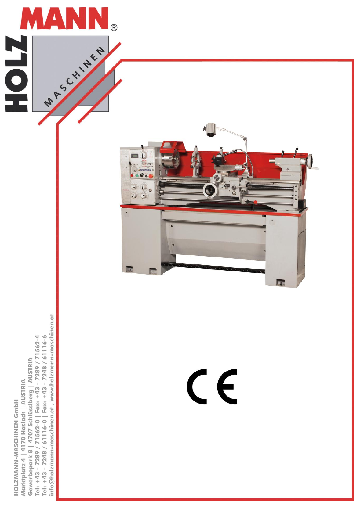
Přečtěte si pečlivě tento
návod před prvním
použitím!
Technické změny a tis-
kové chyby vyhrazeny!
Read the operation manual
carefully before first use!
Technical data subject to
changes, errors excepted!
CZ
Návod na obsluhu
Soustruh na kov
EN
User Manual
Metal turning lathe
ED1000F
Soustruh na kov
Metal turning lathe
Vydání/Edition: 2011 – Revize 01 – CZ/EN
Page 2

OBSAH / INDEX
1.1 Specifikace ovládacích prvků a komponent stroje ............................................................................... 7
1.2 Technické údaje ................................................................................................................................. 8
1.3 Účel použití ...................................................................................................................................... 10
1.3.1 Pracovní podmínky ................................................................................................................................................ 10
1.4 Nedovolené použití .......................................................................................................................... 10
1.5 Všeobecné bezpečnostní pokyny ...................................................................................................... 11
1.6 Další rizika ....................................................................................................................................... 12
1.7 Ustavení stroje ................................................................................................................................. 13
1.7.1 Vybalení ................................................................................................................................................................. 13
1.7.2 Čištění .................................................................................................................................................................... 13
1.7.3 Instalace ................................................................................................................................................................. 13
1.8 Mazání ............................................................................................................................................. 13
1.8.1 Koník ...................................................................................................................................................................... 13
1.8.2 Převodovka ............................................................................................................................................................ 14
1.8.3 Suportová skříň ...................................................................................................................................................... 14
1.8.4 Ozubená kola převodovky ..................................................................................................................................... 14
1.8.5 Další části ............................................................................................................................................................... 14
1.9 Symboly ovládání ............................................................................................................................. 15
1.10 Kontrola otáček vřetene ................................................................................................................. 16
1.11 Volba závitu a posunu .................................................................................................................... 16
1.12 Závity a zadávací tabulky ................................................................................................................ 17
1.13 Řezání závitů .................................................................................................................................. 19
1.14 Montáž sklíčidla ............................................................................................................................. 20
1.15 Seřízení soustruhu .......................................................................................................................... 22
1.16 Vedení suportové skříně ................................................................................................................. 22
1.17 Příčné sáně..................................................................................................................................... 22
1.18 Horní suport ................................................................................................................................... 23
1.19 Matice příčného suportu ................................................................................................................ 23
1.20 Spoj koník – lože stroje ................................................................................................................... 23
1.21 Constructional indication ................................................................................................................ 25
1.22 Proper usage .................................................................................................................................. 28
1.23 Incorrect usage ............................................................................................................................... 28
1.24 Safety instructions .......................................................................................................................... 28
1.25 Unpacking and Installation ............................................................................................................. 31
1.25.1 Unpacking ............................................................................................................................................................ 31
1.25.2 Cleaning ............................................................................................................................................................... 31
1.25.3 Installation ........................................................................................................................................................... 31
1.26 Lubrication ..................................................................................................................................... 31
HOLZMANN Maschinen Austria www.holzmann-maschinen.at Strana 2
Soustruh na kov / Metal turning lathe ED1000F
Page 3

1.26.1 Headstock ............................................................................................................................................................ 31
1.26.2 Gearbox ............................................................................................................................................................... 32
1.26.3 Apron ................................................................................................................................................................... 32
1.26.4 Change gears........................................................................................................................................................ 32
1.26.5 Other parts ........................................................................................................................................................... 32
1.27 Operation symbols ......................................................................................................................... 33
1.28 Spindle speed control ..................................................................................................................... 34
1.29 Thread and feed selection .............................................................................................................. 34
1.30 Feed and thread tables ................................................................................................................... 35
1.31 Thread cutting operation ................................................................................................................ 37
1.32 CHUCKS AND CHUCK MOUNTING.................................................................................................... 39
1.33 Lathe alignment ............................................................................................................................. 40
1.34 Saddle strip .................................................................................................................................... 40
1.35 Cross slide ...................................................................................................................................... 40
1.36 Compound rest .............................................................................................................................. 41
1.37 Cross slide nut ................................................................................................................................ 41
1.38 Tailstock bed clamp ........................................................................................................................ 41
1.39 Objednávky náhradních dílů ........................................................................................................... 92
1.40 Spare part order ............................................................................................................................. 92
HOLZMANN Maschinen Austria www.holzmann-maschinen.at Strana 3
Soustruh na kov / Metal turning lathe ED1000F
Page 4

CZ
BEZPEČNOSTNÍ SYMBOLY
VÝZNAM SYMBOLŮ
EN
SAFETY SIGNS
DEFINITION OF SYMBOLS
CZ
UPOZORNĚNÍ! Dbejte bezpečnostních pokynů! Opomíjení předpisů a
pokynů může vést k těžkým zraněním nebo dokonce smrti.
EN
ATTENTION! Ignoring the safety signs and warnings applied on the ma-
chine as well as ignoring the security and operating instructions can cause
serious injuries and even lead to death.
CZ
PŘEČTĚTE SI TENTO NÁVOD! Přečtěte si pozorně tento návod na
obsluhu a údržbu a seznamte se s ovládacími prvky, abyste používali stroj
správně a předcházeli tak zraněním nebo závadám.
EN
READ THE MANUAL! Read the user and maintenance manual carefully
and get familiar with the controls n order to use the machine correctly and
to avoid injuries and machine defects.
CZ
OCHRANNÉ PROSTŘEDKY! Obsluha má povinnost nosit ochranu
sluchu, ochranné brýle a vhodnou obuv.
EN
PROTECTIVE CLOTHING! The operator is obligated to wear proper
ear protection, safety goggles and safety shoes
CZ
CE-KONFORMITA – Tento výrobek je v souladu se směrnicemi ES.
EN
EC-CONFORM - This product complies with the EC-directives.
BEZPEČNOSTNÍ SYMBOLY / SAFETY SIGNS
HOLZMANN Maschinen Austria www.holzmann-maschinen.at Starna 4
Soustruh na kov / Metal turning lathe ED1000F
Page 5

PŘEDMLUVA
HOLZMANN MASCHINEN GmbH
A-4170 Haslach, Marktplatz 4
Tel 0043 7289 71562 - 0
Fax 0043 7289 71562 – 4
[email protected]
PO-PÁ 8-12 a 13-17hod. GMT+1
Vážený zákazníku!
Tento návod k použití obsahuje důležité informace a pokyny k uvedení do provozu, údržbě a provozu soustruhu na kov ED 1000F.
Tento návod na obsluhu je nedílnou součástí stroje a musí být u něj uchován pro případné
pozdější použití. Pokud stroj předáváte třetí osobě, vždy návod přiložte!
Dodržujte bezpečnostní pokyny!
Před prvním použitím si pozorně přečtěte tento návod na obsluhu. To Vám usnadní práci
se strojem a pomůže předcházet chybám a případným škodám. Dodržujte bezpečnostní
pokyny a dbejte výstrah. Opomíjení bezpečnostních pokynů může vést k vážným škodám
na zdraví.
Z důvodu neustálého vývoje našich produktů se mohou vyobrazení nebo obsah tohoto návodu
mírně lišit od skutečnosti. V případě zjištění nedostatků této dokumentace nás o těchto laskavě
informujte.
Technické změny a tiskové chyby vyhrazeny!
Autorské právo
© 2011
Tato dokumentace je chráněna autorským právem. Všechna práva vyhrazena! Obzvláště kopíro-
vání, přetisk, překlady nebo použití fotografií a vyobrazení budou trestně stíhány – soudní místo
je v Rohrbachu!
Adresa na služby zákazníkům
HOLZMANN Maschinen Austria www.holzmann-maschinen.at Strana 5
Soustruh na kov/Metal turning lathe ED1000F
Page 6
TECHNICKÉ ÚDAJE
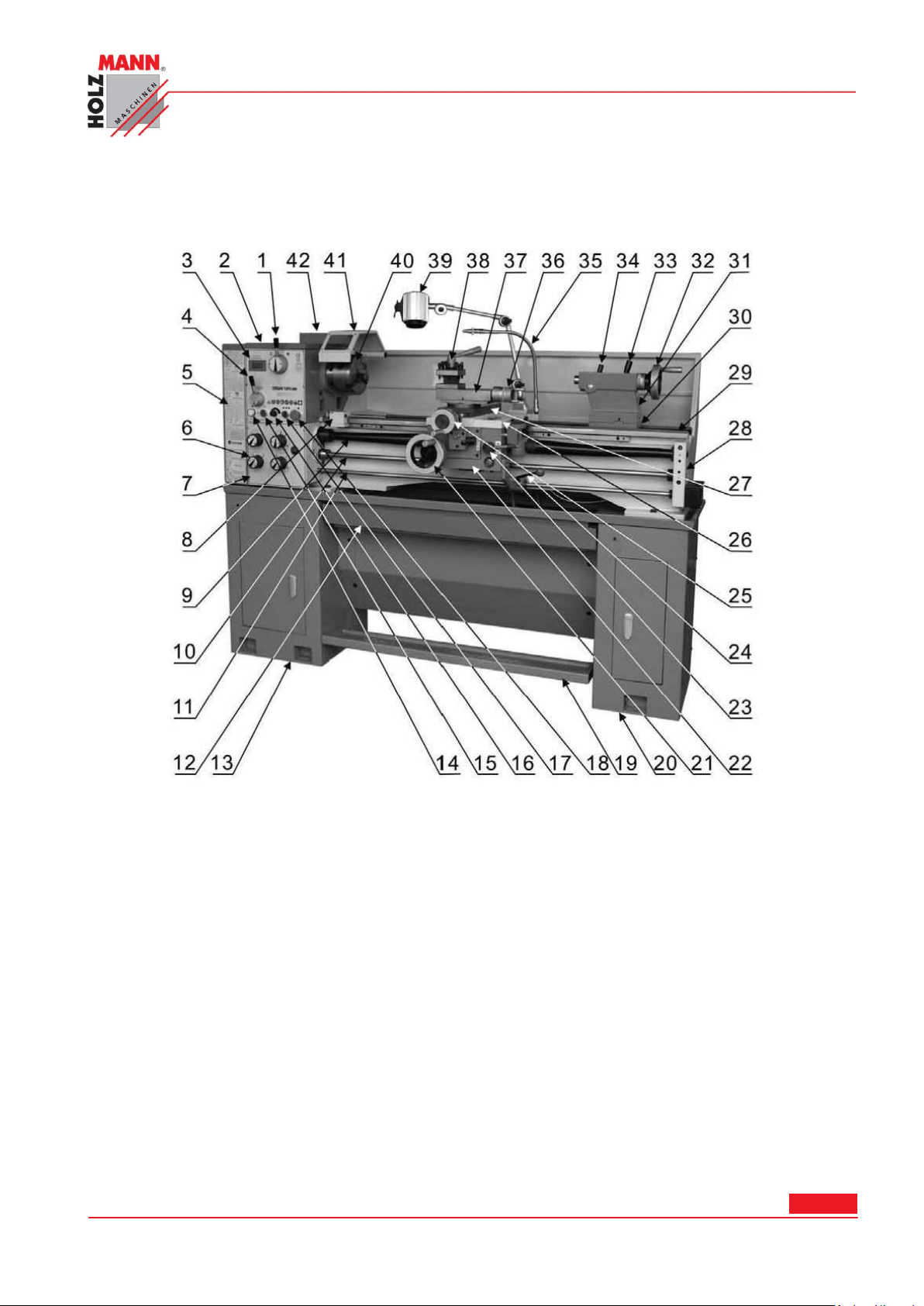
1. Páka otáček
22. Suportová skříň
2. Vřeteník
23. Páka pro řezání závitů
3. Digitální displej otáček vřetene
24. Ovládací páka
4. Volba směru posunu
25. Točítko příčného suportu
5. Výměna kol převodovky
26. Horní část suportové skříně
6. Volba rychlosti posunu
27. Držák nástroje
7. Převodovka posunu
28. Uložení koníku v lože stroje
8. Kluzná spojka
29. Lože stroje
9. Vedení vřetene s krytem
30. Podstavec koníka
10. Pohybový šroub
31. Koník
11. Šroub posuvu suportu
32. Točítko koníka
12. Olejová vana
33. Aretační páka koníka
13. Patka levá
34. Upínací páka pinoly
14. Provozní lampa
35. Chladící systém
15. Přepínač pro chlazení
36. Točítko horního suportu
16. Páka otáček vřetene
37. Horní suport
17. Startovací tlačítko
38. Držák nářadí
1.1 Specifikace ovládacích prvků a komponent stroje
HOLZMANN Maschinen Austria www.holzmann-maschinen.at Strana 6
Soustruh na kov/Metal turning lathe ED1000F
Page 7

18. Vypínač nouzového zastavení
39. Pracovní osvětlení
19. Provozní brzda/Nožní brzda
40. Vřeteno a sklíčidlo
20. Patka pravá
41. Bezpečnostní kryt sklíčidla
21. Točítko podélných saní
42. Elektrická přípojka
Max. točný průměr nad ložem
13’’ (330mm)
Max. točný průměr nad suportem
7.8” (198mm)
Max. točný průměr nad můstkem
18.7’’ (476mm)
Max. délka hrotu
39.37’’ (1000mm)
Šířka lože
7.32’’ (186mm)
Otvor koníku
2’’ (51mm)
Zámek vačky-uložení
D5
Kónus koníku
MT No.6
Otáčky vřetene
70-1900 ot./min nebo 40-1800ot./min
Zdvih – horní support
3.5’’ (90mm)
Zdvih – příčný suport
7’’ (178mm)
Zdvih – hlavní sáně
37.8’’ (960mm)
Příčný posun
0.0006’’-0.015’’ (0.014-0.38mm)
Podélný posun
0.002’’-0.0154’’ (0.052-0.392mm)
Uložení koníku
MT Nr.4
Zdvih pinoly
4’’ (100mm)
Řezací nástroj (max. volba)
0.79’’x0.79’’ (20X20mm)
Závity palcové
4-56 TPI
Závity metrické
0.4-7mm
Soustruhy jsou určeny výhradně pro výrobu a opravu hřídelí, vřeten a malých i velkých obrobků.
Mohou být zároveň použity pro řezání metrických a imperiálních měrných jednotek. Jejich obsluha
je snadná, jsou spolehlivé, jednoduché na servis, velice produktivní a o nízké hladině hluku.
1.2 Technické údaje
HOLZMANN Maschinen Austria www.holzmann-maschinen.at Strana 7
Soustruh na kov/Metal turning lathe ED1000F
Page 8
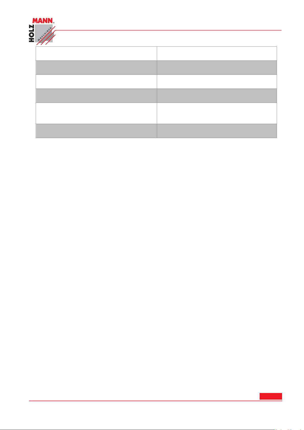
Zavity trapézové
0.2-3 M.P
Závity diametrické
8-112 D.P
Hmotnost (netto)
1320 Lbs (600kg)
Hmotnost (brutto)
1430 Lbs(650kg)
Rozměr balení (DXŠXV)
76.38’’X29.92’’X59.84’’
(1940x760x1520mm)
Výkon motoru
2HP (1.5kw)
HOLZMANN Maschinen Austria www.holzmann-maschinen.at Strana 8
Soustruh na kov/Metal turning lathe ED1000F
Page 9

BEZPEČNOST
Relativní vlhkost
při 40°C max. 50%
při 20°C max. 90%
Provozní teplota
od +5°С do +40°С
max. nadmořská výška
1000 m
min. osvětlení
500 Lux
1.3 Účel použití
Stroj se smí používat pouze v bezvadném technickém stavu, při dodržení všech pokynů k pro-
vozu a bezpečnostních pokynů, při vědomí nebezpečnosti stroje! Závady, které mohou ovlivnit
bezpečnost stroje, ihned odstraňte!
Je obecně zakázáno měnit nebo odstraňovat bezpečnostní prvky a zařízení stroje!
1.3.1 Pracovní podmínky
Stroj je určen pro provoz za následujících podmínek:
Stroj není určen pro venkovní použití.
Stroj není určen pro provoz v oblasti elektromagnetické zátěže ("Elektrosmog").
Stroj není určen pro provoz na pracovištích, kde jsou plyny, vlhkost apod., které mohou
poškodit izolaci elektroinstalace stroje, korozi nebo jiná poškození.
Stroj není určen do provozů s rizikem požáru nebo exploze.
Stroj není určen do prostředí s výskytem vibrací, protože tyto snižují výkon stroje, přesnost
opracování a životnost stroje.
Opracování hořlavých nebo výbušných materiálů je striktně zakázáno (např. surové alumini-
um, hořčík atd.).
1.4 Nedovolené použití
Provoz stroje za podmínek přesahujících rámec použití uvedený v tomto návodu není
dovolen.
Provoz stroje bez ochranných prostředků není dovolen.
Není dovolena demontáž nebo deaktivace ochranných prvků.
Případné změny na konstrukci stroje nejsou dovoleny.
Provoz stroje bez chladiva je zakázán.
Není dovolené přetěžování stroje.
Je zakázaný provoz stroje při nedostatečném mazání nebo nedostatečné hladině oleje.
Provoz stroje způsobem a k účelům, které neodpovídají 100% pokynům v tomto návodu,
je výslovně zakázán.
Za škody a zranění způsobená jiným než ke svému účelu určenému použití stroje
nenese společnost HOLZMANN-MASCHINEN jakoukoliv odpovědnost nebo záruku.
HOLZMANN Maschinen Austria www.holzmann-maschinen.at Strana 9
Soustruh na kov/Metal turning lathe ED1000F
Page 10
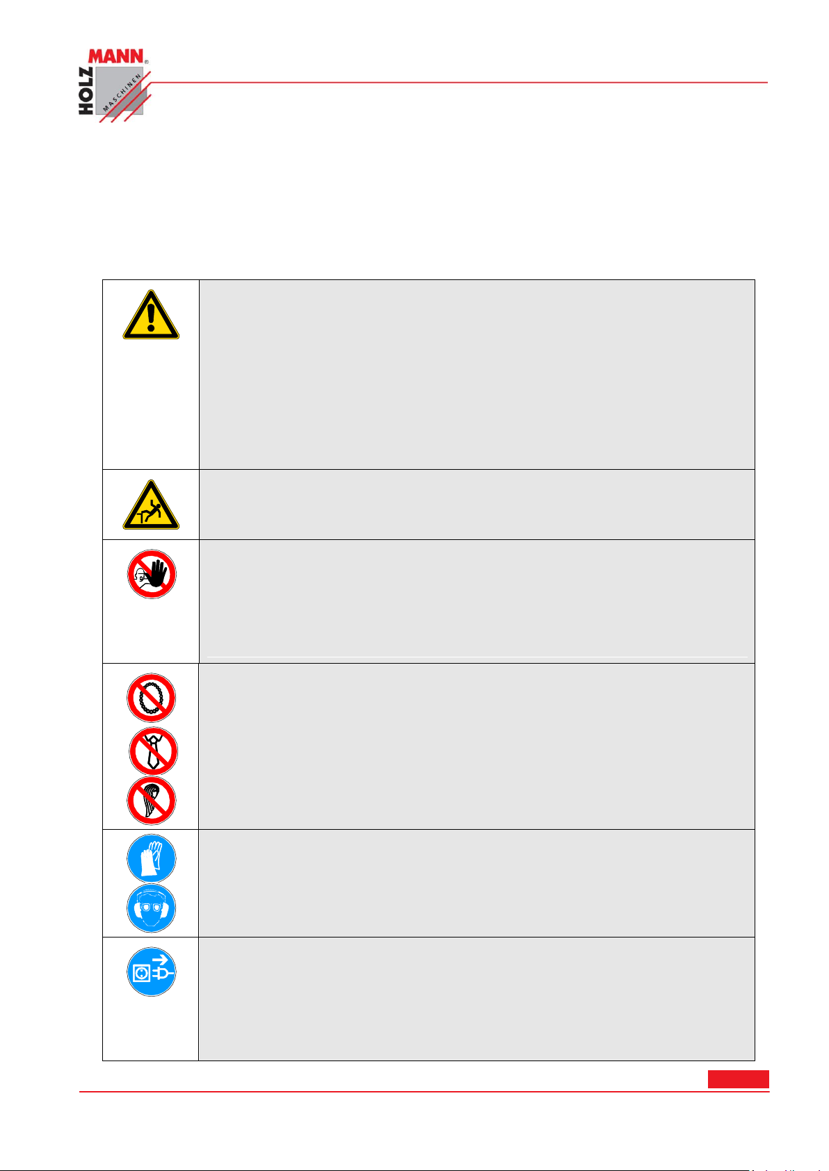
1.5 Všeobecné bezpečnostní pokyny
Pracoviště a podlahu kolem stroje udržujte v čistotě a zbavte ji
případného oleje, tuku a zbytků od zpracovávaného materiálu!
Zajistěte dostatečné osvětlení pracoviště, kde se stroj nachází!
Stroj nepoužívejte venku!
Práce se strojem je při únavě, ztrátě koncentrace případně pod
vlivem léků, alkoholu nebo drog přísně zakázána!
Stoupání na stroj je zakázáno!
Hrozí těžká zranění při pádu nebo při převrácení stroje!
Soustruh na kov ED1000F smí být obsluhován pouze zaškoleným
personálem.
Nepovolané osoby, zejména děti, a nezaškolený personál se nesmí
zdržovat v blízkosti běžícího stroje!
Při práci se strojem nenoste volné šperky, dlouhý oděv, kravaty. Ne-
bezpečné jsou i dlouhé rozpuštěné vlasy.
Volné části oděvu apod. se mohou namotat na rotující části a
způsobit tak vážná zranění!
Při práci používejte vhodné ochranné prostředky
(ochranné rukavice, ochranné brýle, sluchátka atd.)!
Před výkonem údržby nebo při seřizování odpojte stroj ze sítě! Před
odpojením ze sítě vypněte stroj hlavním vypínačem (OFF)!
Pro transport nebo manipulaci se strojem nikdy nepoužívejte síťový
kabel!
Výstražné štítky a/nebo nálepky na stroji, které jsou již nečitelné nebo chybějí,
musejí být okamžitě obnoveny!
Pro zabránění vadné funkce stroje, jeho poškození nebo škodám na zdraví dbejte
VŽDY následujících pokynů:
HOLZMANN Maschinen Austria www.holzmann-maschinen.at Strana 10
Soustruh na kov/Metal turning lathe ED1000F
Page 11

Na stroji je pouze několik málo komponent, které vyžadují údržbu. Není nutné na
stroji cokoliv demontovat. Opravy svěřte výhradně kvalifikovanému opraváři!
Příslušenství: Používejte pouze příslušenství doporučené společností HOLZMANN!
V případě dotazů nebo potíží se obracejte na náš zákaznický servis.
1.6 Další rizika
I při dodržování bezpečnostních předpisů a pokynů pro správné použití stroje hrozí další rizika:
Nebezpečí poranění rukou/prstů od rotujícího vrtáku.
Nebezpečí zranění při kontaktu s částmi, které vedou elektrický proud.
Nebezpečí těžkých zranění od namotání vlasů nebo volných částí oděvů na rotující části
stroje.
Poranění sluchu, pokud obsluha preventivně nenosí ochranu sluchu.
Nebezpečí poranění očí při odletujících částech.
Nebezpečí od uvolněných chemických látek z opracovávaného materiálu.
Tato rizika je možné minimalizovat při dodržování všech bezpečnostních pokynů, údržby a
péče o stroj a při vhodném používání stroje zaškolenou obsluhou.
HOLZMANN Maschinen Austria www.holzmann-maschinen.at Strana 11
Soustruh na kov/Metal turning lathe ED1000F
Page 12
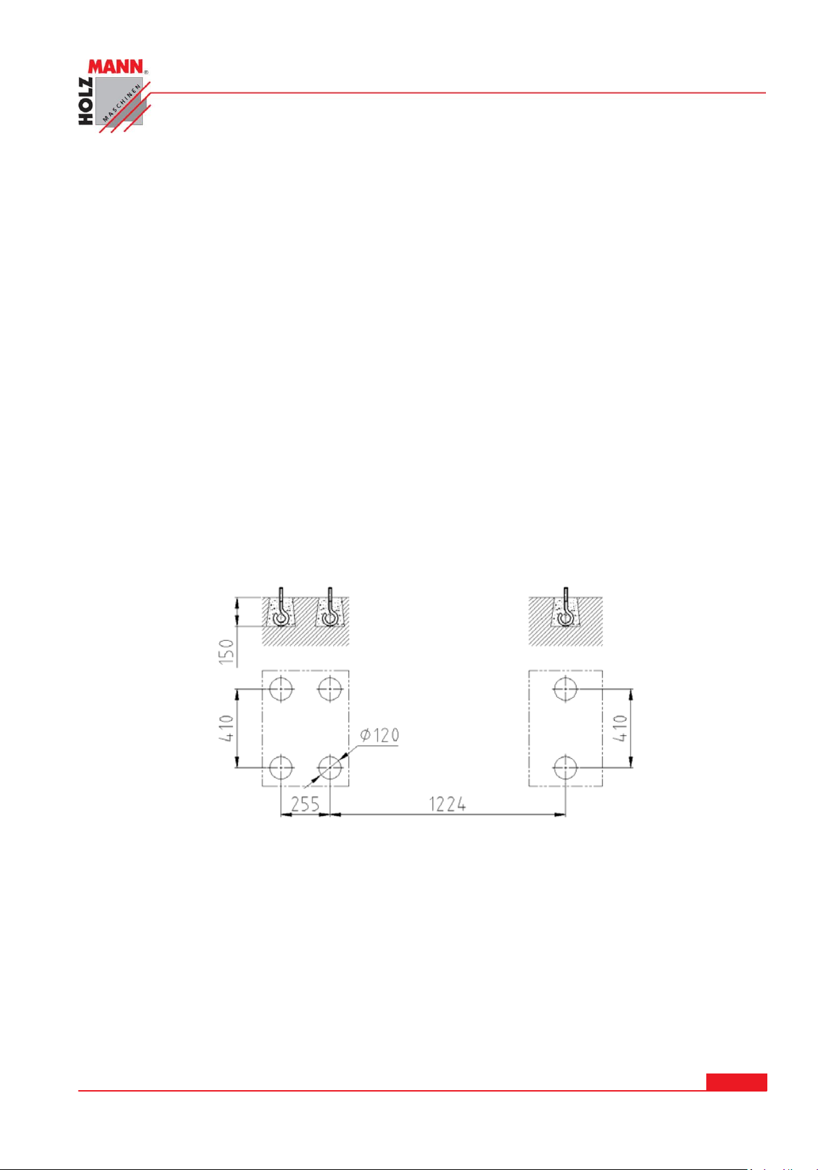
UVEDENÍ DO PROVOZU
1.7 Ustavení stroje
1.7.1 Vybalení
Vyložte stroj pomocí jeřábu za použití upínacích desek a závěsných šroubů.
Udržujte zařízení v rovnováze, zatímco koník a lože stroje posunujete vpravo. Vyvarujte se
použití vázacích řetězů, neboť hrozí poškození tažné hřídele soustruhu a vodícího vřetene.
Soustruh zvedejte opatrně a umístěte ho na podlahu nebo na dílenský stůl.
1.7.2 Čištění
Odstraňte antikorozní ochranu příp. zbytky tuku Kerosinem (parafínem) nebo terpentínem ze
všech vedení a převodů ještě před uvedením do provozu. Nepoužívejte ředidla ani jiná ro-
zpouštědla. Naolejujte ihned všechny neošetřené (světlé) plochy stroje. Použijte olej nebo tuk
vhodný pro ozubená kola.
1.7.3 Instalace
Umístěte soustruh na pevnou plochu. Betonová podlaha je pro stroj nejlepším základem. Pokud je
to nutné, použijte podstavec. Ujistěte se, že máte pro obsluhu a údržbu stroje dostatek místa.
Ustavte přesně vedení lože, poté utáhněte šrouby základu a zkontrolujte výsledný stav.
1.8 Mazání
Zkontrolujte mazání následujících částí před započetím prací na stroji:
1.8.1 Koník
Uložení vřeteníku je v olejové lázni. Ujistěte se, že hladina oleje dosahuje na značku olejoznaku.
Pro výměnu oleje sejměte vypouštěcí šroub na spodní straně vřeteníku a nechte olej vytéct. Pro
doplnění oleje sundejte kryt vřeteníku. Stav hladiny oleje kontrolujte pravidelně. První výměnu
oleje proveďte po 3 měsících, následně byste měli měnit olej jednou ročně.
HOLZMANN Maschinen Austria www.holzmann-maschinen.at Strana 12
Soustruh na kov/Metal turning lathe ED1000F
Page 13

1.8.2 Převodovka
Sundejte kryt pro odkrytí plnícího hrdla. První výměnu oleje proveďte po 3 měsících, následně
postačí měnit olej jednou ročně.
1.8.3 Suportová skříň
Olejová lázeň je naplněna olejem Shell Tellus 32. Olej doplňujte nalévacím hrdlem. Kontrolujte
pravidelně stav hladiny oleje pomocí olejoznaku na přední straně. První výměna oleje by měla být
provedena po třech měsících provozu, následně postačí jednou ročně. Pro odčerpání oleje sundejte vypouštěcí šroub na spodní straně zástěry.
1.8.4 Ozubená kola převodovky
Jednou měsíčně namažte kola převodovky strojovým olejem nebo tukem.
1.8.5 Další části
Další mazací místa jsou na hřídeli pohonu, ručních kolech, suportové skříni a na koníku. Tyto
promazávejte pravidelně maznicí.
Jednou ročně aplikujte tenkou vrstvu oleje na lože stroje a další neošetřené části jako pinola
koníku apod.
HOLZMANN Maschinen Austria www.holzmann-maschinen.at Strana 13
Soustruh na kov/Metal turning lathe ED1000F
Page 14
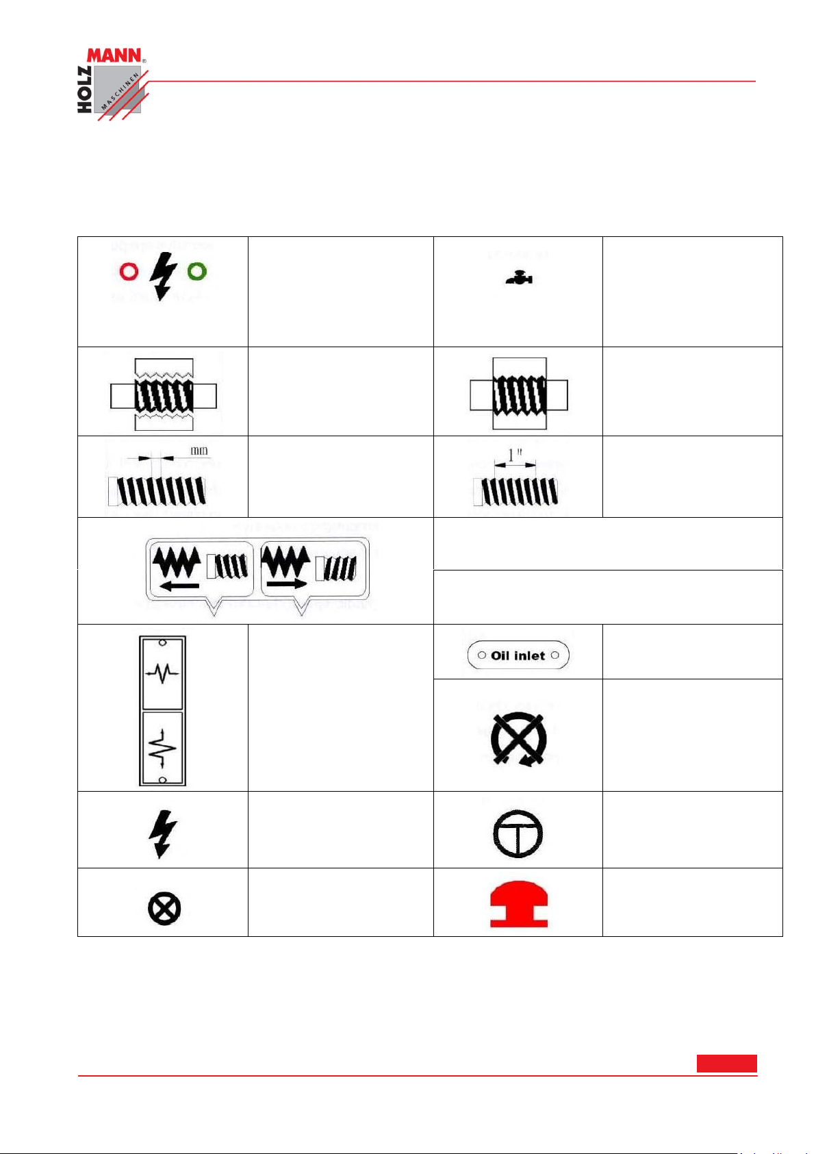
OBSLUHA
Červený
Zelený
Power
Zelený: zapnuto
Červený: vypnuto
Červený
Zelený
Chlazení
Zelený: zapnuto
Červený: vypnuto
Svěrná matice otevřená
Svěrná matice zavřená
Metrický závit
Imperialní závit
Pravý závit a podélný posun ke straně vřeteníku
(levé vyobrazení)
Levý závit a podélný posun ke straně vřeteníku
(pravé vyobrazení)
Podélný posun zapadlý
(nahoře).
Oba podélné posuny
odpojeny (uprostřed).
Příčný posun zapadlý
(dole).
Přívod oleje
Neměňte rychlost za
provozu stroje.
Elektrické ovládání (Ne-
bezpečí)
Zářez
Světelná kontrolka
Stop
1.9 Symboly ovládání
HOLZMANN Maschinen Austria www.holzmann-maschinen.at Strana 14
Soustruh na kov/Metal turning lathe ED1000F
Page 15

1.10 Kontrola otáček vřetene
A. Kontrola před spuštěním
Ujistěte se, že bylo provedeno mazání tak, jak je popsáno výše.
Pokud se hlavní vřeteno otáčí, jsou v provozu převodovka a posun. Přepínač vpřed/vzad (4) se
musí nacházet v pozici „neutrál“. Posun (6) a páka volby sklíčidlo/závit (6) se nacházejí v odpojené pozici. Za těchto podmínek lze točítko (21) a točítko (25) ručně ovládat.
B. Otáčení hlavního vřetene
Otáčení hlavního vřetene se volí přepínačem pro pohyb vpřed/vzad.
C. Rychlost hlavního vřetene
Rychlost (vysoká/nízká) hlavního vřetene se volí na regulátoru rychlosti (1). Jak pro vysoké, tak
pro nízké stupně rychlosti jsou k dispozici 2 různé pozice. Pro nastavení správné rychlosti se po-
dívejte do rychlostního schématu.
Nikdy neměňte rychlost, než se motor/vřeteno zcela zastaví!
Přizpůsobení rychlosti může být podpořeno ručním otáčením hlavního vřetene.
D. Zajetí stroje
Zajetí musí být provedeno při nejnižších otáčkách vřetene. Nechte stroj běžet při těchto otáčkách
přibližně 1 hodinu. Zkontrolujte pak nepravidelný chod, např. Neobvyklý hluk, nevyváženost
apod. Pokud je všechno v pořádku, zvyšujte postupně rychlost. Práce při nejvyšších otáčkách je
možná nejdříve po 10 hodinách provozu, resp. „zajetí" soustruhu.
E. Provoz
Používejte pouze sklíčidla doporučená společností Holzmann Maschinen GmbH.
Maximální rychlost 1255 ot./min pro upínací desku o průměru 250mm nesmí být překročena.
Pokud se neprovádí řezání závitů nebo není potřeba automatického posunu, měla by být páka v
pozici neutrálu pro zajištění odpojení vodícího vřetene a vodící hřídele. Pro vyvarování se
zbytečného opotřebení nesmí být spojen ukazatel nastavení závitu s vodícím šroubem.
1.11 Volba závitu a posunu
Veškeré závity a posuny jsou vyobrazeny na tabulkách na přední straně převodovky. Volí se
pomocí páky volby posunu(6) na převodovce.
A. Manuální provoz
Pohyb hlavního vřetene se provede točítkem (21), příčné sáně pomocí točítka (25) a horní sáně
pomocí točítka (36).
B. Závit a tabulka posunu
Pro volbu podélného popřípadě příčného posunu, tak jako pro nastavení anglických (imperiálních)
nebo metrických závitů, použijte odpovídající tabulku, která se nachází na soustruhu.
C. Automatický posun
HOLZMANN Maschinen Austria www.holzmann-maschinen.at Strana 15
Soustruh na kov/Metal turning lathe ED1000F
Page 16
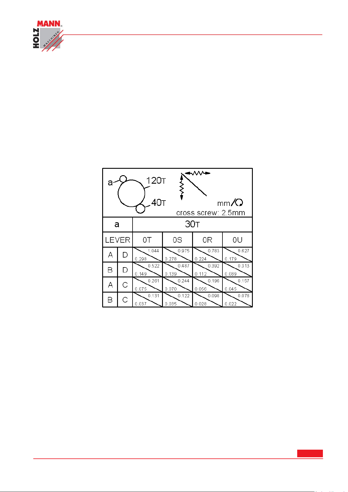
Spojte nejprve mechanickou převodovku 40T a vložené ozubené kolo 127T volbou směru posunu (6), následně nastavte volič posunu/závitu (6) do pozice vlevo a páku (6) do jednoho z otvorů 1-5, druhou do jednoho z otvorů A-E, tím se otáčí tažný hřídel. Pokud ukazuje páka (6)
směrem nahoru, je nastaven podélný posun. Pokud ukazuje páka směrem dolů, je zvolen příčný
posun.
D. Řezání závitu
Směr řezání závitu se volí volbou směru posunu (4). Za chodu stroje se otáčí vodící vřeteno,
pokud přesunete páku pro volbu posunu a páku posun/závit.
1.12 Závity a zadávací tabulky
(A). Zadávací tabulka:
Podélný a příčný posun pro metrický soustruh
HOLZMANN Maschinen Austria www.holzmann-maschinen.at Strana 16
Soustruh na kov/Metal turning lathe ED1000F
Page 17
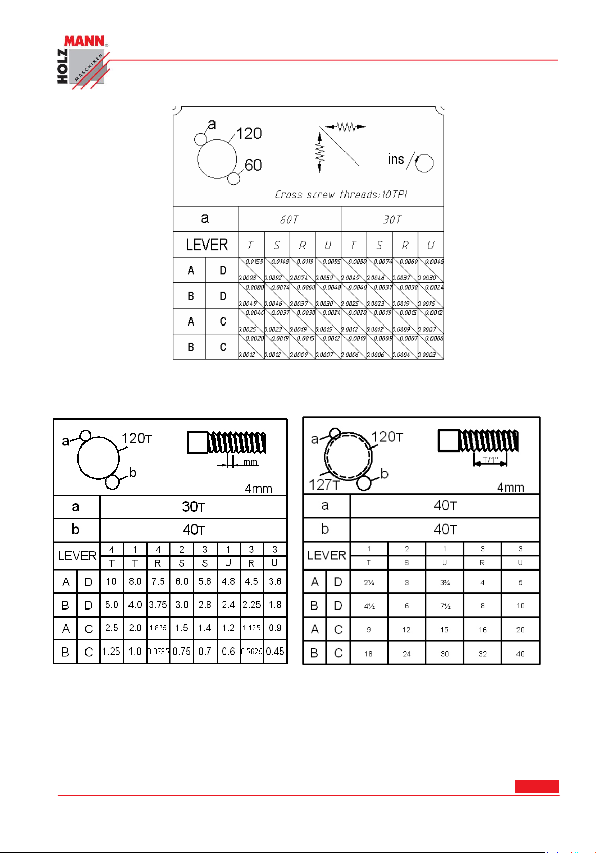
Podélný a příčný posun pro anglický (imperiální systém) soustruh
(B) Tabulka závitů
Tabulka závitů pro metrický soustruh
HOLZMANN Maschinen Austria www.holzmann-maschinen.at Strana 17
Soustruh na kov/Metal turning lathe ED1000F
Page 18
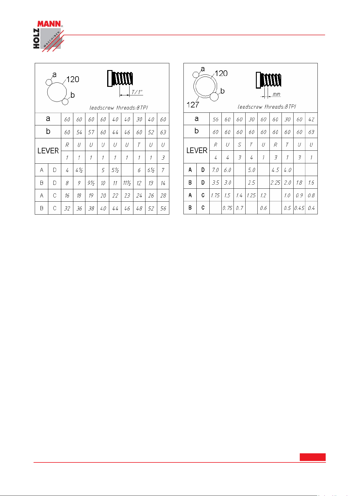
Tabulka závitů pro anglický soustruh
1.13 Řezání závitů
Abyste docílili požadovaného závitu podle uvedené tabulky, musíte nejprve namontovat do
převodovky odpovídající kombinaci ozubených kol.
Nechte otáčet vodící vřeteno, zatímco přestavíte páku závit/posun do správné pozice a přesvědčte
se, že je páka volby posunu zapadlá.
Před opracováváním nastavte páku pro řezání závitů (23) do pozice, aby stála volba posunu osy v
pozici neutrálu a nebyla tedy zapadlá.
Směr, ve kterém by měl být závit řezán, lze zvolit přestavením páky pro posun (6) na vřeteníku.
K dispozici je 31 různých anglických závitů, jakož i 26 metrických, které lze zvolit přestavením
páky posunu osy.
(A). Ukazatel nastavení závitu
Ukazatel nastavení závitu se nachází na pravé straně suportové skříně a používá se k řezání
závitů. Pro snížení opotřebení se doporučuje ukazatel nastavení závitu po použití deaktivovat.
Při řezání závitů se doporučuje použití hodinek pro závity.
Níže najdete tabulky pro metrické a anglické (imperiální) závity:
Stroje s metrickým vodícím vřetenem (pouze metrické závity):
HOLZMANN Maschinen Austria www.holzmann-maschinen.at Strana 18
Soustruh na kov/Metal turning lathe ED1000F
Page 19
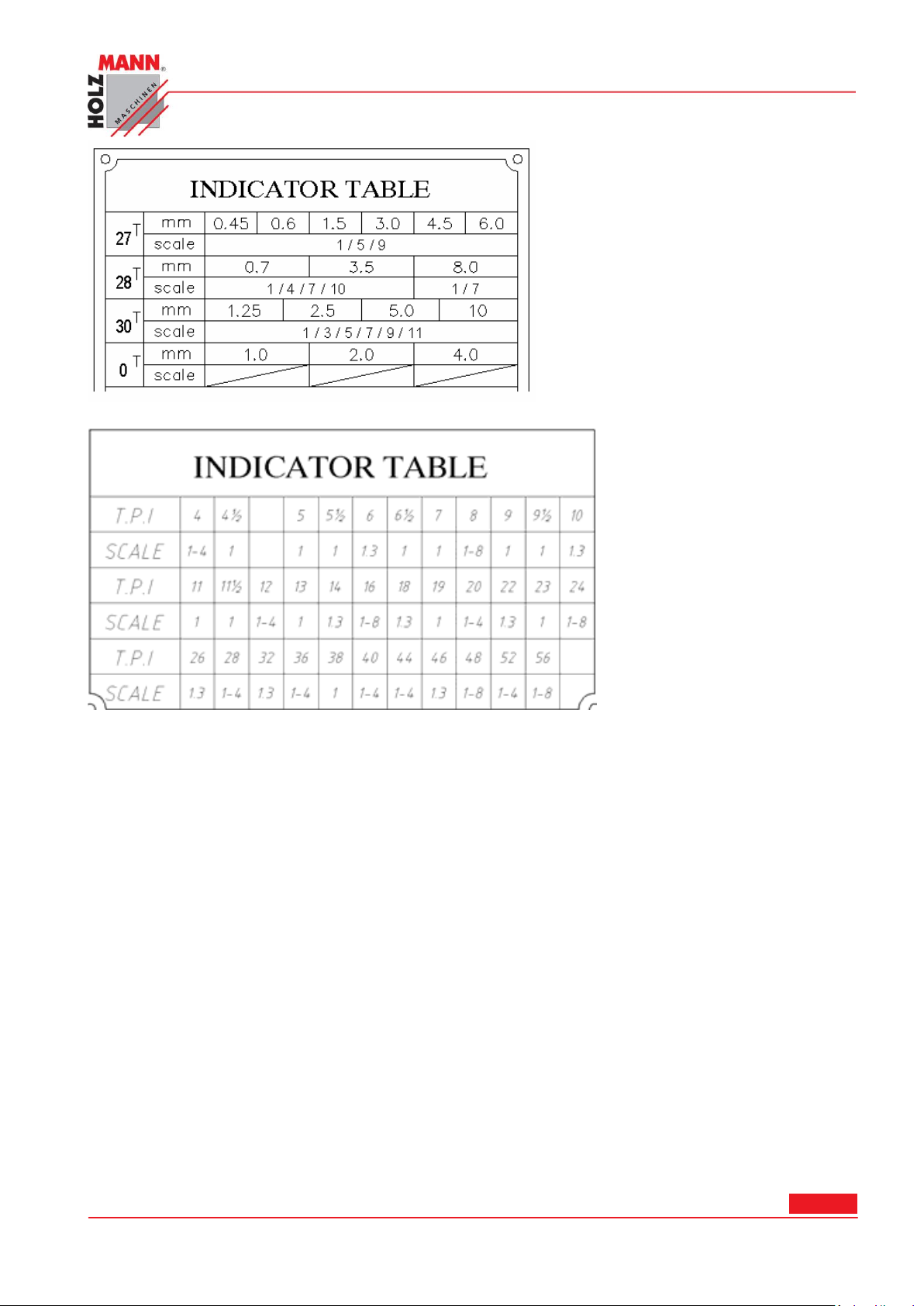
Stroje s anglickým vodícím vřetenem (pouze anglické závity):
1.14 Montáž sklíčidla
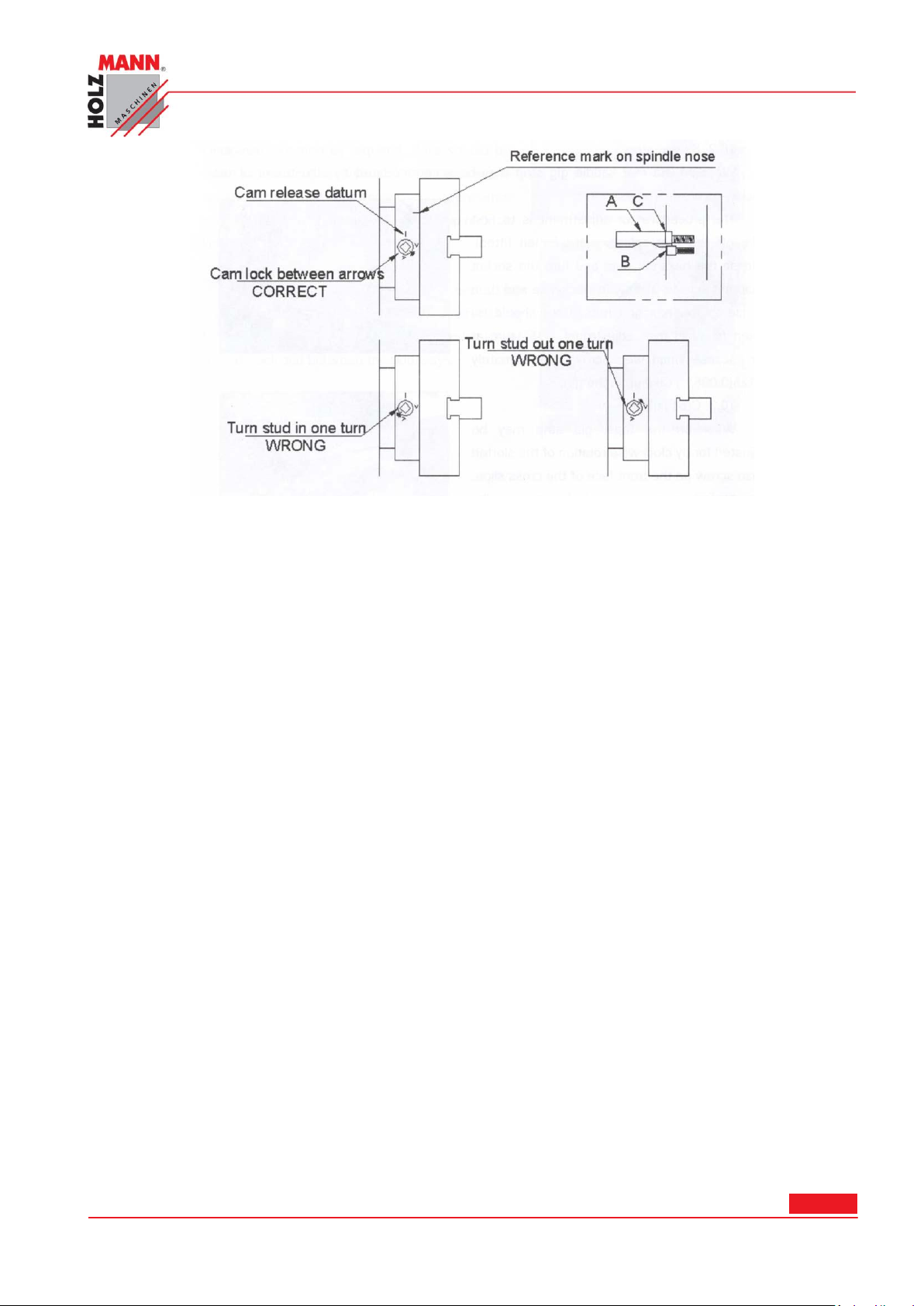
Pokud chcete montovat případně demontovat sklíčidlo nebo lícní desku, ujistěte se nejprve, že
jste zajistili vačky (A). Pak sundejte fixační šrouby (B) a nastavte každé tlačítko tak, aby byl
kroužek (C) v ose se zadní částí sklíčidla.
Nyní namontujte sklíčidlo nebo lícní desku na hlavu vřetene a dotáhněte šest vaček v řadě. Pokud
jsou zcela dotažené, měla by se linka všech zámků vaček nacházet mezi dvěma značkami V na
hlavě vřetene. Pokud se i jediný zámek vačky nenachází zcela mezi těmito značkami, sundejte
sklíčidlo nebo lícní desku a slícujte/srovnejte znovu červík podle vyobrazení níže. Před každým
použitím dotáhněte fixační šroub (B) na každém červíku.
Nevyměňujte sklíčidlo nebo lícní desku mezi rozdílnými soustruhy bez kontroly správného utažení
vaček.
HOLZMANN Maschinen Austria www.holzmann-maschinen.at Strana 19
Soustruh na kov/Metal turning lathe ED1000F
Page 20
HOLZMANN Maschinen Austria www.holzmann-maschinen.at Strana 20
Soustruh na kov/Metal turning lathe ED1000F
Page 21
ÚDRŽBA A SERVIS
1.15 Seřízení soustruhu
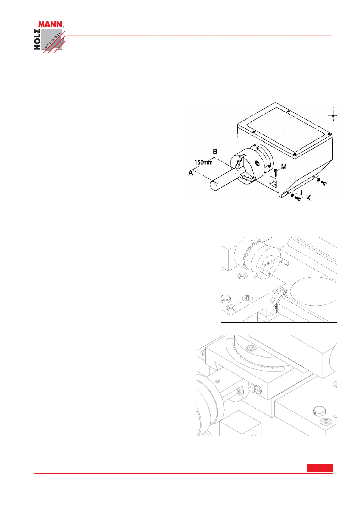
Po smontování soustruhu musí být provedeno
jeho seřízení. Seřízení se musí pravidelně kontrolovat, aby byla zajištěna stálá přesnost
soustruhu. Proveďte následující úkony: Použijte
ocelovou tyč o průměru cca 50mm a délce cca
200 mm. Vložte ji a zajistěte ve sklíčidle.
Následně vysoustružte třísku 0,5mm délky cca
150 mm a změřte rozdíl síly třísky od měřícího
bodu A (0,5mm) k měřícímu bodu B. Pokud
naměříte rozdíl, musí být vřeteník seřízen. Pro
korekci rozdílu povolte šroub (K) s kontra maticí
(J), která svírá vřeteník na loži a drží ho v poloze. Seřiďte polohu vřeteníku tím, že změníte
hloubku zapuštění šroubu. Opakujte výše
uvedený postup, dokud nebude měření odpovídat. Pak bude zajištěno, že bude soustruh
řezat správně.
1.16 Vedení suportové skříně
Jemné nastavení vedení se provede pomocí imbusového
šroubu.
Pro nastavení sundejte zadní lapač nečistot. Uvolněním še-
stihranné matice a otáčením imbusovým šroubem ve
směru pohybu hodinových ručiček nastavíte vedení supor-
tové skříně.
Dejte si pozor na to, abyste šroub nepřetočili, otáčka im-
busovým šroubem o 45° odpovídá přenastavení o cca.
0.125 (0.005").
1.17 Příčné sáně
Jemné nastevní vedení se provede pomocí šroubu
se zářezem. Tím se přestaví úkosová lišta a vymezí
vůle mezi vedením a sáněmi.
HOLZMANN Maschinen Austria www.holzmann-maschinen.at Strana 21
Soustruh na kov/Metal turning lathe ED1000F
Page 22
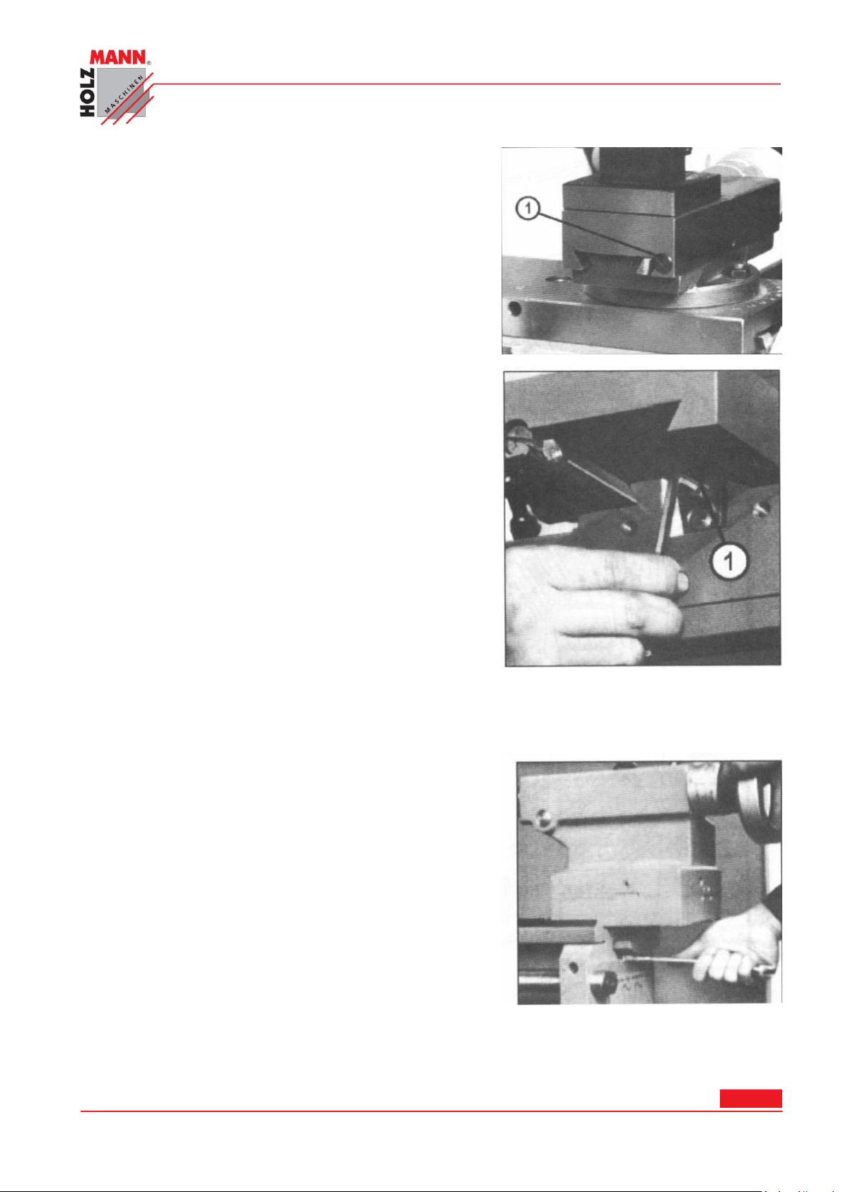
1.18 Horní suport
Postup je shodný jako u příčných sání.
Tímto úkonem se nejprve uvolní stejné šrouby na pro-
tilehlé straně a po slícování znovu utáhnou, aby se
vedení ustavilo v nové pozici.
1.19 Matice příčného suportu
Postup je shodný jako u horních sání.
Tímto úkonem se nejprve uvolní stejné šrouby na pro-
tilehlé straně a po slícování znovu utáhnou, aby se
vedení ustavilo v nové pozici.
Dejte si pozor na to, abyste šroub nepřetočili, otáčka
imbusovým šroubem o 45° odpovídá přenastavení o cca.
0.125 (0.005").
1.20 Spoj koník – lože stroje
Na spodní straně koníku se nachází úhelníková upínací
čelist, ve které je prostrčený červík koníku, a který je
sešroubovaný samosvornou maticí. Pomocí upínací páky
koníku může být koník zafixován v jakékoliv pozici. Musí
být zajištěno, aby při povolené pozici upínací páky vyka-
zovala upínací čelist nepatrnou vůli vůči loži a v
utaženém stavu byla upínací čelist v loži zatlačená, aby
měl koník pevné spojení s ložem stroje.
Otáčením samosvorné matice lze seřizovat svěrný bod.
PREFACE
Dear Customer!
HOLZMANN Maschinen Austria www.holzmann-maschinen.at Strana 22
Soustruh na kov/Metal turning lathe ED1000F
Page 23

HOLZMANN MASCHINEN GmbH
A-4170 Haslach, Marktplatz 4
Tel 0043 7289 71562 - 0
Fax 0043 7289 71562 – 4
This manual contains Information and important instructions for the installation and correct use of
the heavy duty metal turning lathe ED1000F.
This manual is part of the machine and shall not be stored separately from the machine. Save it
for later reference and if you let other persons use the machine, add this instruction manual to
the machine.
Please read and obey the security instructions!
Before first use read this manual carefully. It eases the correct use of the machine and
prevents misunderstanding and damages of machine and the user’s health.
Due to constant advancements in product design construction pictures and content may diverse
slightly. However, if you discover any errors, inform us please.
Technical specifications are subject to changes!
Please check the product contents immediately after receipt for any eventual transport
damage or missing parts. Claims from transport damage or missing parts must be
placed immediately after initial machine receipt and unpacking before putting the machine into operation. Please understand that later claims cannot be accepted anymore.
Copyright
© 2011
This document is protected by international copyright law. Any unauthorized duplication, translation or use of pictures, illustrations or text of this manual will be pursued by law – court of jurisdiction is A-4020 Linz, Austria!
CUSTOMER SERVICE CONTACT
HOLZMANN Maschinen Austria www.holzmann-maschinen.at Strana 23
Soustruh na kov/Metal turning lathe ED1000F
Page 24
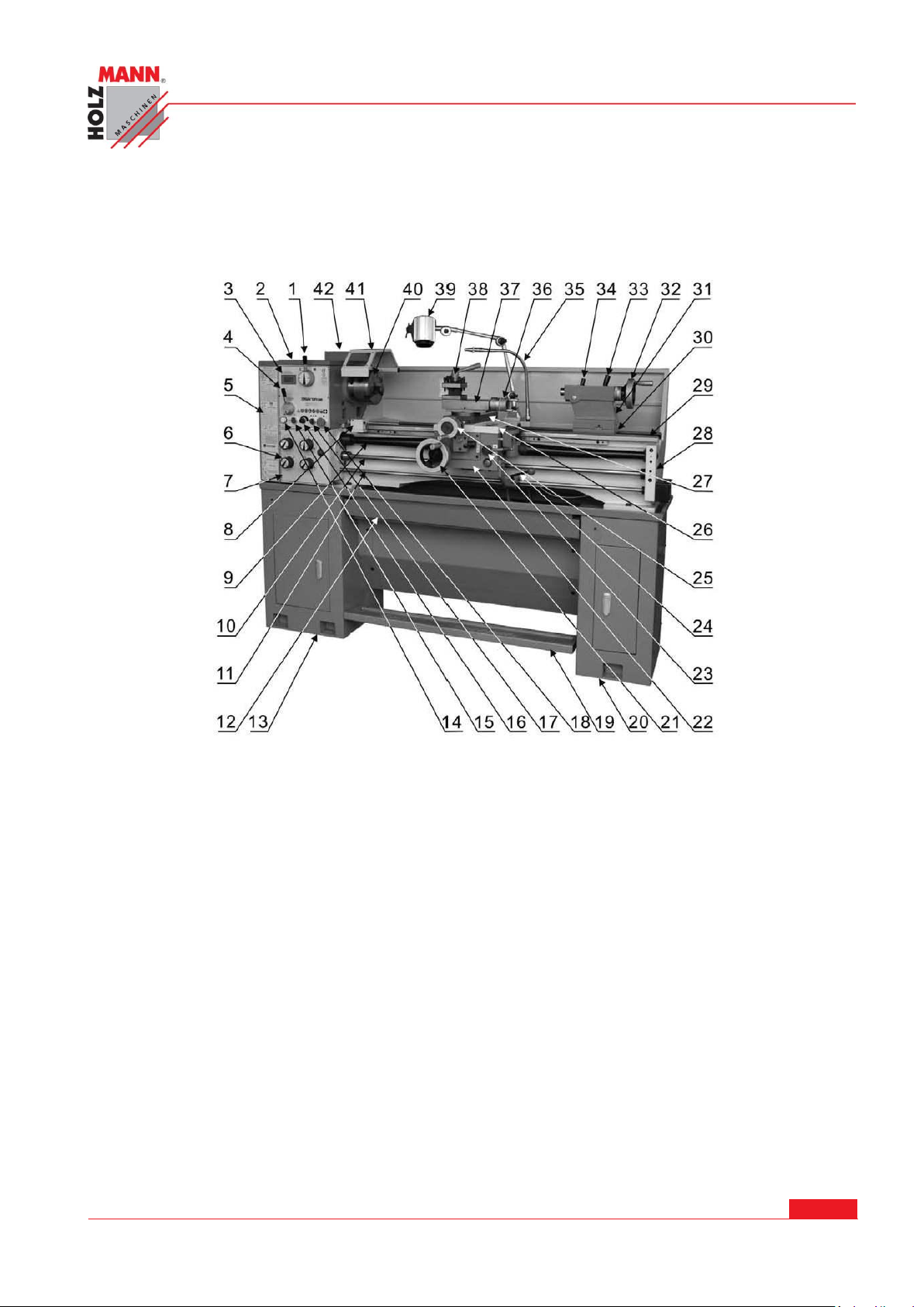
CHYBA! POMOCÍ KARTY DOMŮ POUŽIJTE U TEXTU, KTERÝ SE MÁ ZDE ZOBRAZIT, STYL
1. Speed selector
2. Headstock
3. DRO for spindle speeds
4. Feed direction selector
5. Change gear box
6. Feed box selectors
7. Feed gear box
8. Demarcation frame work
9. Leadscrew & safety guide
10, Feed rod
11. Control bar
12. Oil tray
13. Left stand
14. Indication light
15. Coolant knob switch
16. Spindle speeds Adjustable knob
17. Fast-stop button
18. Emergency press button
19. Foot brake
20. Right stand
21. Longitudinal traverse hand wheel
22. Apron
23. Threading cutting Engagement lever
24. Control lever
25. Cross travel control hand wheel
26. Saddle
27. Cross slide
28. Support casting
29. Bed ways
30. Tailstock set-over screw
31. Tailstock
32. Quill travel hand wheel
33. Tailstock lock lever
34. Quill lock lever
35. Coolant system
36. Compound rest hand wheel
37. Compound rest
38. Tool post
39. Work light
40. Spindle and chuck – spindle und futter
41. Safety cover for chucks
42. Electric box Elektroanschluss
ÜBERSCHRIFT 1.
TECHNICAL DATA
1.21 Constructional
indication
HOLZMANN Maschinen Austria www.holzmann-maschinen.at Seite 24
Metalldrehbank/Metal turning lathe ED1000F
Page 25

CHYBA! POMOCÍ KARTY DOMŮ POUŽIJTE U TEXTU, KTERÝ SE MÁ ZDE ZOBRAZIT, STYL
ÜBERSCHRIFT 1.
HOLZMANN Maschinen Austria www.holzmann-maschinen.at Seite 25
Metalldrehbank/Metal turning lathe ED1000F
Page 26

CHYBA! POMOCÍ KARTY DOMŮ POUŽIJTE U TEXTU, KTERÝ SE MÁ ZDE ZOBRAZIT, STYL
MAX. Swing over bed
13’’ (330mm)
MAX. Swing over cross slide
7.8” (198mm)
MAX. Swing over gap
18.7’’ (476mm)
MAX. Distance between centers
39.37’’ (1000mm)
Bed width
7.32’’ (186mm)
Spindle bore
2’’ (51mm)
Cam lock system
D5
Spindle taper
MT No.6
Spindle speed
70-1900rpm or 40-1800rpm
Compound slide travel
3.5’’ (90mm)
Cross slide travel
7’’ (178mm)
Carriage travel
37.8’’ (960mm)
Cross-feed
0.0006’’-0.015’’ (0.014-0.38mm)
Longitudinal feed
0.002’’-0.0154’’ (0.052-0.392mm)
Tailstock taper
MT No.4
Tailstock barrel travel
4’’ (100mm)
Cutting tool (Max. section)
0.79’’x0.79’’ (20X20mm)
Range of inch threads
4-56 TPI
Range of metric threads
0.4-7mm
Range of module threads
0.2-3 M.P
Range of diametral threads
8-112 D.P
Weight (Net)
1320 Lbs (600kg)
Weight(Shipping)
1430 Lbs(650kg)
Crate size (LXBXH)
76.38’’X29.92’’X59.84’’(1940x760x1520mm)
Motor output
2HP (1.5kw)
ÜBERSCHRIFT 1.
Bench lathe are especially suitable for machining, tool toms and repairing working shops to machine shafts, spindle, sleeves, and disc work piece of middle or small types. They can also be
used to cut metric thread and imperial, and with compact construction and reasonable composition, they can cut very well. They are easy and reliable to operate, convenient to repair high in
efficiency, and low noise.
HOLZMANN Maschinen Austria www.holzmann-maschinen.at Seite 26
Metalldrehbank/Metal turning lathe ED1000F
Page 27
CHYBA! POMOCÍ KARTY DOMŮ POUŽIJTE U TEXTU, KTERÝ SE MÁ ZDE ZOBRAZIT, STYL
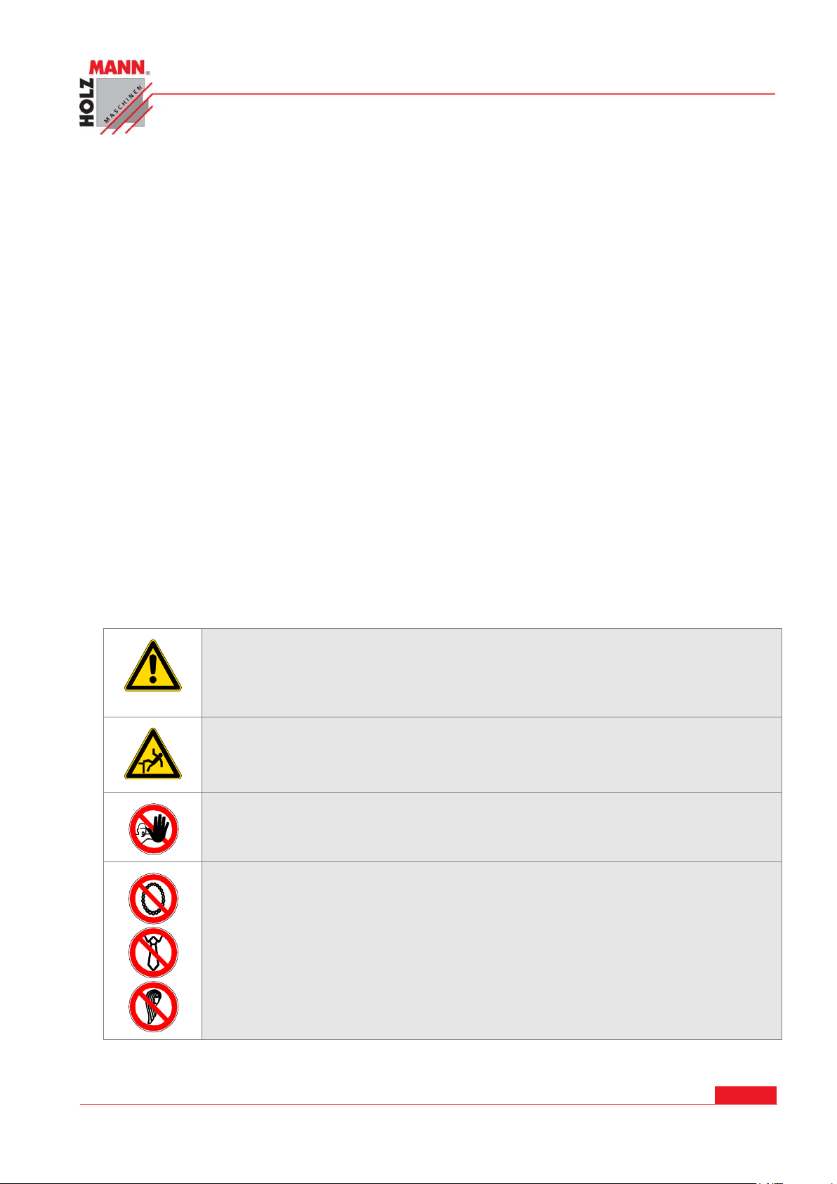
Do not operate the machine at insufficient lighting conditions.
Do not operate the machine outdoors.
Do not operate the machine when you are tired, when your concentration is
impaired, and/ or under the influence of drugs, medication or alcohol.
Climbing onto the machine is forbidden! Heavy injuries by falling down or by
tilting of the machine are possible.
The machine shall be used only by trained persons.
Non authorized persons, especially children, shall be kept away from the work
area.
Do not wear loose clothing, long hair openly or loose jewellery like necklaces
etc. when operating the machine
They might be catched by rotating parts and cause serious injuries.
ÜBERSCHRIFT 1.
SAFETY GUIDELINES
1.22 Proper usage
Holzmann Maschinen cannot be held responsible for any injuries or damages if there was performed manipulation or adjustments to the machine.
For another usage and resulting damages or injuries HOLZMANN MASCHINEN
doesn’t assume any responsibility or guarantees.
1.23 Incorrect usage
Operation of the machine that doesn’t agree with this manual is forbidden!
Operation without the safety devices is not allowed.
You mustn’t remove the safety devices!
Incorrect is the usage for materials which aren’t mentioned in this manual.
Changes of the machine’s construction are forbidden.
For another usage and resulting damages or injuries HOLZMANN MASCHINEN
doesn’t assume any responsibility or guarantees.
1.24 Safety instructions
Warning labels and/or other labels on the machine must be replaced when they were removed.
HOLZMANN Maschinen Austria www.holzmann-maschinen.at Seite 27
Metalldrehbank/Metal turning lathe ED1000F
Page 28

CHYBA! POMOCÍ KARTY DOMŮ POUŽIJTE U TEXTU, KTERÝ SE MÁ ZDE ZOBRAZIT, STYL
Use proper safety clothing and devices when operating the machine (, safety
goggles, ear protectors, safety shoes …)! Do not wear safety gloves for operating because they decrease the working accuracy and they might be pulled into
the saw blade.
Before any maintenance you have to disconnect the panel saw from the power
source. Never use the plugged cable for transporting or manipulating the machine.
1. Please follow the safety guidelines to avoid injury.
2. Check whether the voltage and frequency on the plaque coincided with the power source before us-
ing the machine in operation.
3. The power plug and the power source must be firmly connected.
4. Use only well-constructed power lines. Do not pull the power cord. The power cable must be re-
moved from hot, wet and greasy areas. You also may not come with any sharp or pointed objects in
contact.
5. The machine must be on level ground.
6. In case of problems, turn off power and check and repair the machine.
7. If the machine works, you seal off the work against unauthorized entry.
8. Keep the workplace clean. Do not use the machine at wet, highly flammable or slightly illuminated
places.
9. Do not let children are observed in the machine and uninvolved in the safety distance.
10. Work carefully.
11. Do not wear loose clothing, gloves, chains and jewelry, to avoid entanglement in moving parts. Non-
skid footwear is recommended. Wear protective hair covering to conceal long hair completely. Roll
up long sleeves up to the upper arm.
12. Operate the machine not to alcohol and drug use in fatigue.
13. If you take medicines, you should contact their doctor to get a work permit.
14. Set the machine on a flat area on.
15. Maintain the machine regularly, keep the tools sharp and clean.
16. Make sure that the ON / OFF switch is OFF before connecting the machine to the power to prevent
accidental starting of the machine.
17. Use only attachments and the products that are recommended by our company.
18. Do not leave objects near or on the machine to avoid accidents.
19. You can repair damaged parts or replace them immediately with new ones if necessary
20. Never remove chips with your hand from the workspace of the machine.
21. Let the machine unattended and leave the machine only after all rotating parts have stopped. Drag
the power plug after leaving the machine.
22. Wear eye protection.
23. Never attempt any operation or adjustment if procedure is not understood.
24. Keep fingers away from revolving parts and cutting tools while in operation.
25. Never force cutting action.
26. Never perform an abnormal or little used operation without study and use of adequate blocks, jigs
stops, fixtures ECT.
27. Use of shop manual such as “machinery’s handbook” or similar is recommended for cutting speeds
feeds and operation detail.
HOLZMANN Maschinen Austria www.holzmann-maschinen.at Seite 28
Metalldrehbank/Metal turning lathe ED1000F
ÜBERSCHRIFT 1.
Page 29

CHYBA! POMOCÍ KARTY DOMŮ POUŽIJTE U TEXTU, KTERÝ SE MÁ ZDE ZOBRAZIT, STYL
ÜBERSCHRIFT 1.
28. Do not remove drive cover while machine is in operation. Make sure it is always closed.
29. Always remove chuck key, even when machine is not in operation.
30. Do not attempt to adjust or remove tools when in operation.
31. Always keep cutters sharp.
32. Never use in an explosive atmosphere or where a spark could ignite a fire.
33. Always use identical replacement parts when servicing.
WARNING: Do allow familiarity (gained from frequent use of your lathe) to become commonplace. A careless fraction of a second can allow for sever injury.
We want to point out that when working with machine tools are always a residual risk remains
that is not mentioned in the above safety precautions. There is always the utmost care when
working with such machines. Especially for machine operators already experienced the accident risk increases by routine.
HOLZMANN Maschinen Austria www.holzmann-maschinen.at Seite 29
Metalldrehbank/Metal turning lathe ED1000F
Page 30
CHYBA! POMOCÍ KARTY DOMŮ POUŽIJTE U TEXTU, KTERÝ SE MÁ ZDE ZOBRAZIT, STYL
ÜBERSCHRIFT 1.
ASSEMBLY
1.25 Unpacking and Installation
1.25.1 Unpacking
Unload the machine with a tackle, using clamping plates and eyebolts. Keep the machine in balance by moving the tailstock and the bed slide to the right. Avoid using sling chains as they could
damage to feed rod and leadscrew. Lift the lathe carefully and place it softly into the floor or
workbench.
1.25.2 Cleaning
Before taking the machine into operation, using kerosene (paraffin) or white spirit to remove the
anti-corrosive coating or grease from all slideways and gear train. Don’t use lacquer thinner or
other caustic solvents. Oil all bright machine surfaces immediately after cleaning. Use heavy oil or
grease on the changes gears.
1.25.3 Installation
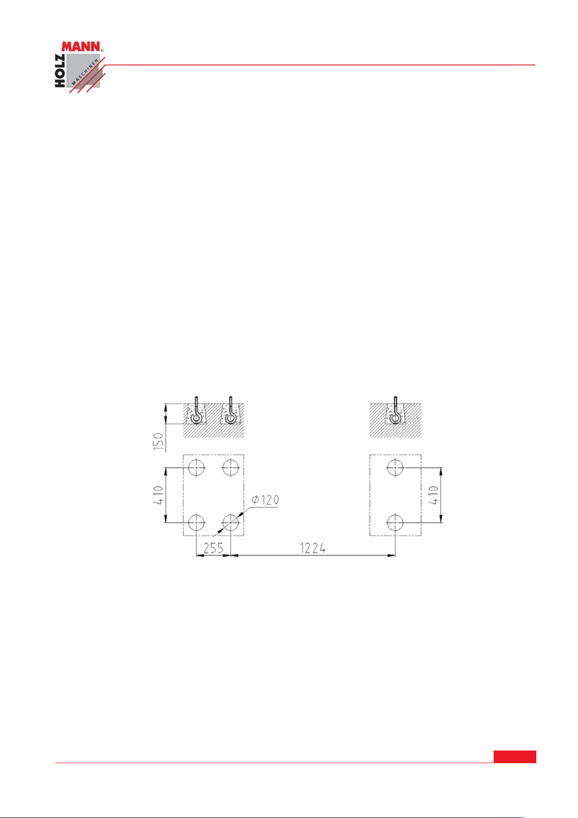
Place the lathe on a solid foundation. A concrete floor is the best base for the machine. (If necessary, use an under frame operational). Make sure there is sufficient area around the lathe for
easy work and maintenance. Use a precision level on the bedways to make further adjustment for
level condition, then tighten the foundation bolts evenly and finally recheck for level condition.
1.26 Lubrication
Before putting the lathe into operation, make the following lubrication check.
1.26.1 Headstock
The bearing of the headstock turns in an oil bath. Ensure that the oil level reaches three quarters
of the quarters of the oil gauge glass.
For exchanging the oil, remove the end cover and the change gears with swing frame. Drain off
the oil by removing the drain plug on the bottom of the headstock. To fill, take off the headstock
cover. Check the oil level regularly. The first oil change should be made after 3 month, then
change it once a year.
HOLZMANN Maschinen Austria www.holzmann-maschinen.at Seite 30
Metalldrehbank/Metal turning lathe ED1000F
Page 31

CHYBA! POMOCÍ KARTY DOMŮ POUŽIJTE U TEXTU, KTERÝ SE MÁ ZDE ZOBRAZIT, STYL
ÜBERSCHRIFT 1.
1.26.2 Gearbox
Remove the end cover to expose the filling plug. Through it the shell tellus 32 is filled to the oil
level in the oil gauge glass regularly. The first oil change should be made after three months, the
change it once a year.
1.26.3 Apron
The oil bath is filled with shell tellus 32 through the filling plug on the right side of the apron.
Check the oil level in the oil gauge glass on the front regular. The first oil change should be made
after three months, then change it once a year. For exchanging the oil, drain away oil by taking
off the drain plug on the bottom of the apron.
1.26.4 Change gears
Lubricate the change gears with thick machine oil or grease once a month.
1.26.5 Other parts
There are other lubricating points on the input shaft bracket of the gearbox, the handwheel on
the apron, the longitudinal and cross slide, the thread dial indicator, the tailstock and the bracket,
use the grease gun to put a few drops of oil from time to time. Lubricate the apron worm and
worm gear, half nut and leadscrew twice a month. Apply a light oil film to the bed way and all
other bright parts like the tailstock quill, feed rod etc once a day.
HOLZMANN Maschinen Austria www.holzmann-maschinen.at Seite 31
Metalldrehbank/Metal turning lathe ED1000F
Page 32
CHYBA! POMOCÍ KARTY DOMŮ POUŽIJTE U TEXTU, KTERÝ SE MÁ ZDE ZOBRAZIT, STYL
ÜBERSCHRIFT 1.
OPERATION INSTRUCTIONS
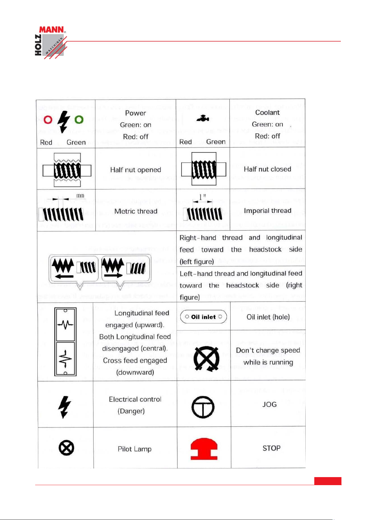
1.27 Operation symbols
HOLZMANN Maschinen Austria www.holzmann-maschinen.at Seite 32
Metalldrehbank/Metal turning lathe ED1000F
Page 33

CHYBA! POMOCÍ KARTY DOMŮ POUŽIJTE U TEXTU, KTERÝ SE MÁ ZDE ZOBRAZIT, STYL
ÜBERSCHRIFT 1.
1.28 Spindle speed control
A. Identification before operation
Ensure that lubrication has been carried out as described before.
When the main spindle is rotating, the gearbox and feed axis of the bedsides are put into opera-
tion.
The forward/reverse switch (4) should be on neutral. The feed axis selector (6) and feed / thread
selector handle (6) are in disengaged position. Under these circumstances, both the longitudinal
travel handwheel (21) and cross travel handle (25) can be operated by hand.
B. Main spindle rotation
The main spindle rotation is selected by forward / reverse switch.
C. Main spindle speed
The speed of the main spindle is selecting by (high / low). Speed selector (1). For both high and
low speed, there are 2 different positions. For correct speed, please refer to the speed chart.
Never change the speed before the motor has stopped completely!
Adjustment the speed can be assisted by turn the main spindle by hand.
D. Running-in
Running in should be done at lowest possible spindle speed. Let the machine to run at lowest
speed for about twenty minutes, and then check for irregularities. If everything seems in order,
gradually increase the speed.
E. Operation
Use only high peripheral speed type chucks.
The maximum spindle speed for chuck plate of 250mm diameter should not be more than
1255rpm.
When thread cutting or auto feeding are not in use, the feed/thread selector should be in neutral
position, so as to ensure disengagement of the leadscrew and the feed rod. To avoid unnecessary
wear, the thread dial indicator should be out of mesh with the leadscrew.
1.29 Thread and feed selection
All threads and feeds are indicated on the tables fitted on the front of the change gearbox. They
are selected with the feed selector handles (6) on the feed gearbox.
A. Manual operation
The carriage is moved by the handle wheel (21), the cross slide by handle wheel (25) and the
compound rest by handle wheel (36). The slide can anchor by turning the lock bolts on the top
and the slide of the slide.
B. Feed and thread tables
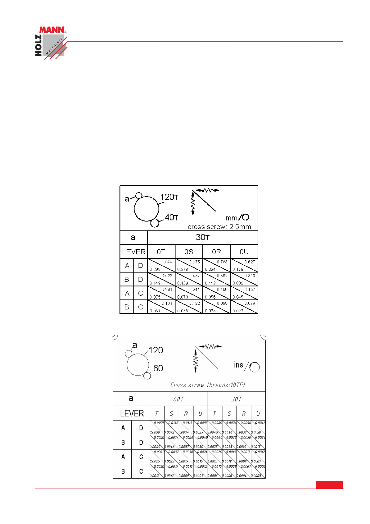
Longitudinal and cross feed table. Metric and imperial thread table.
C. Automatic feed operation
Firstly, engage the 40T change gear at the transmission shaft and the 127T intermediate gear
with feed direction selector (6), next, set the feed/thread selector (6), To the left hand position
HOLZMANN Maschinen Austria www.holzmann-maschinen.at Seite 33
Metalldrehbank/Metal turning lathe ED1000F
Page 34
CHYBA! POMOCÍ KARTY DOMŮ POUŽIJTE U TEXTU, KTERÝ SE MÁ ZDE ZOBRAZIT, STYL
ÜBERSCHRIFT 1.
and position one lever (6) at any of the 1-5 hole, the other at any of A-E holes, thus the feed rod
will rotate. If selector (6) is pushed upward, a longitudinal feed can be obtained. If pushing
downward, across feed will be obtained.
D. Thread cutting operation
The direction of thread cutting is controlled by the feed director (6). By operation feed selector
handle and feed / thread selector handle (6) according to thread pitch, the leadscrew rotate. Operate downward the thread cutting engagement lever (23), it should be engaged with leadscrew,
thus the longitudinal travel of thread cutting feed.
1.30 Feed and thread tables
(A). Feed table:
Longitudinal and cross feed table for metric lathe
Longitudinal and cross feed table for imperial leadscrew
HOLZMANN Maschinen Austria www.holzmann-maschinen.at Seite 34
Metalldrehbank/Metal turning lathe ED1000F
Page 35
CHYBA! POMOCÍ KARTY DOMŮ POUŽIJTE U TEXTU, KTERÝ SE MÁ ZDE ZOBRAZIT, STYL
ÜBERSCHRIFT 1.
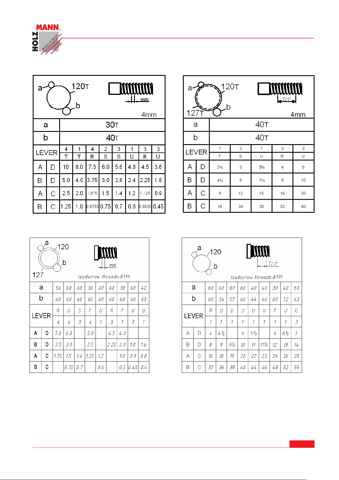
(B) Thread tables
Thread table for metric leadscrew
Thread table for imperial leadscrew
1.31 Thread cutting operation
In order to obtain the desired thread, all correct change gears must be installed in strict accordance with the chart, failure to do so will give incorrect threads.
Rotate the leadscrew by operating the feed/thread selector to any position and be sure the feed
selector handle is engaged. Operate downward the thread cutting engagement lever (6), and it
will be engaged with the leadscrew to obtain the longitudinal travel of carriage, namely, the
thread cutting feed.
HOLZMANN Maschinen Austria www.holzmann-maschinen.at Seite 35
Metalldrehbank/Metal turning lathe ED1000F
Page 36
CHYBA! POMOCÍ KARTY DOMŮ POUŽIJTE U TEXTU, KTERÝ SE MÁ ZDE ZOBRAZIT, STYL
ÜBERSCHRIFT 1.
Make sure the feed axis selector is disengaged (at neutral position) before operating the thread
cutting engagement lever (23) since there is an interlock mechanism between the auto feeding
and thread cutting engagement.
Direction of thread cutting can be chosen by turning the feed directing selector (1) at the headstock. There are 31 Nos. of thread pitches each in Imperial, 26 Nos. of Metric pitches those which
can be obtained by turning the feed selector handles.
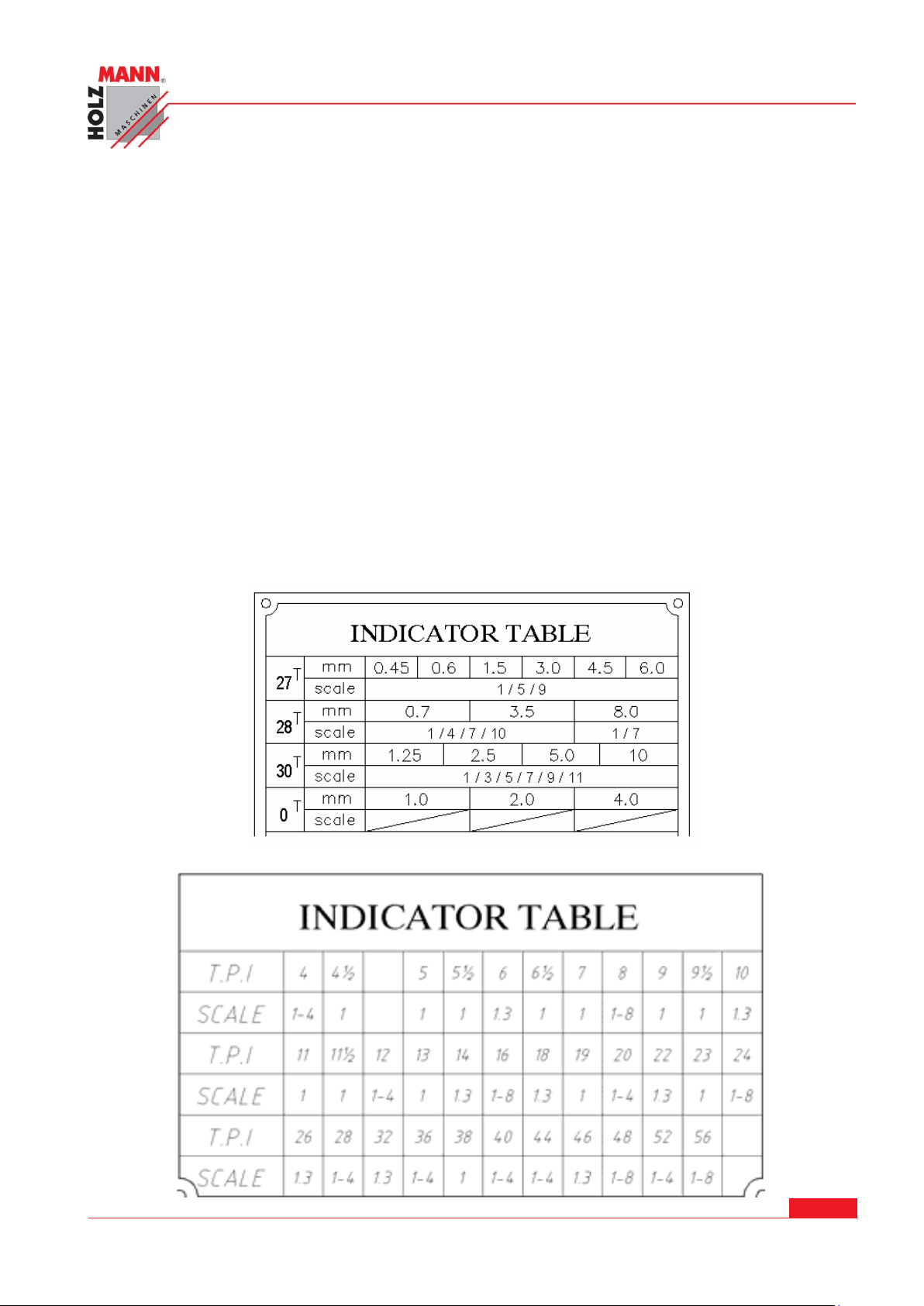
(A).Thread dial indicator
The thread dial indicator is installed on the right hand side of the apron the indicator is used for
thread cutting to engage with the leadscrew. For minimum wear the thread dial indicator should
be disengaged by swing the pinion out of mesh with the leadscrew when not in use.
For these threads it is recommended that the thread dial indicator be used this allows the half nut
of leadscrew to be engaged at the end of each thread cutting pass, provided that they are reengaged in accordance with the indicator table mounted in front and down of the change gear
box.
IN column 1: millimeter pitches to be cut.
27T, 28T, 30T: The number of teeth in "pitch-off gear" arranged to mesh with the leadscrew (this
being selected from the stack, stored on the bottom of the dial spindle)
Dial graduation:
The dial numbers at which the half nut may be engaged under numbers of teeth of pick- off gear.
Metric leadscrew machines (Metric thread only).the table shows:
Imperial leadscrew machines (imperial thread only). The table shows:
HOLZMANN Maschinen Austria www.holzmann-maschinen.at Seite 36
Metalldrehbank/Metal turning lathe ED1000F
Page 37
CHYBA! POMOCÍ KARTY DOMŮ POUŽIJTE U TEXTU, KTERÝ SE MÁ ZDE ZOBRAZIT, STYL
ÜBERSCHRIFT 1.
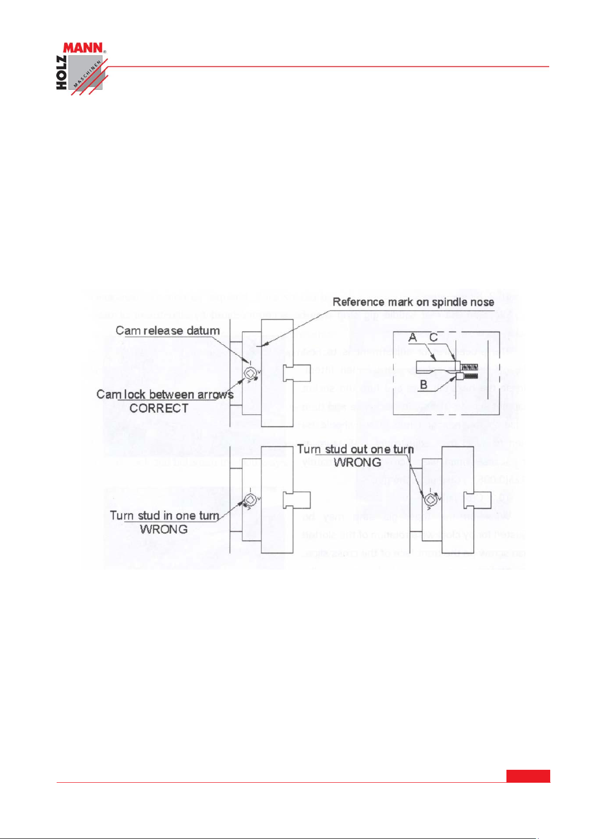
1.32 CHUCKS AND CHUCK MOUNTING
When fitting chucks or faceplates, first ensure that spindle and chuck tapers are be necessary
when mounting a new chuck to re-set the cam lock studs (A). to do this, remove the cap-head
locking screws (B) and set each stud so that the scribed ring (C) is flush with the rear face of the
chuck-with the slot lining up with the locking screw hole.
Now mount the chuck or faceplate on the spindle nose and tighten the six cams in turn. When
fully tightened, the cam lock line on each cam should be between the two V marks on the spindle
nose. If any of the cams do not tighten fully within these limit marks, remove the chuck or faceplate and re-adjust the stud as indicated in the illustration. Fit and tighten the locking screw (B)
at each stud before remounting the chuck for work. A reference mark should be made on each
correctly fitted chuck or faceplate to coincide with the reference mark scribed in the spindle nose.
This will assist subsequent remounting. Do not interchange chucks or faceplate between lathes
without checking for correct cam locking.
HOLZMANN Maschinen Austria www.holzmann-maschinen.at Seite 37
Metalldrehbank/Metal turning lathe ED1000F
Page 38
CHYBA! POMOCÍ KARTY DOMŮ POUŽIJTE U TEXTU, KTERÝ SE MÁ ZDE ZOBRAZIT, STYL
ÜBERSCHRIFT 1.
MAINTENANCES AND SERVICING
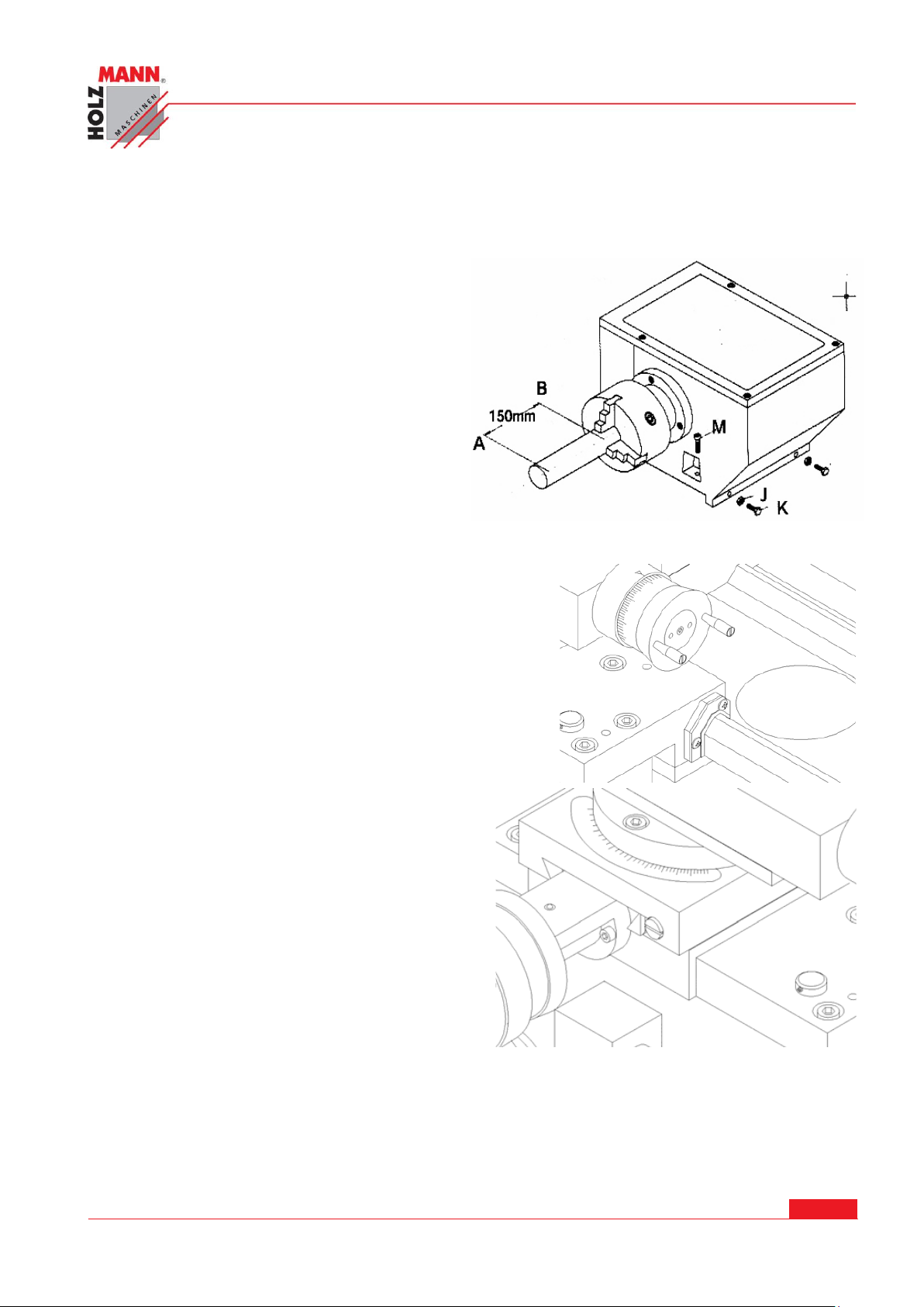
1.33 Lathe alignment
When the lathe is installed and ready for use,
it is recommended to check the machine
alignment before commencing work. Alignment and leveling should be checked regularly
to insure continued accuracy. Adopt this procedure as follow: take a steel bar with a diameter of appr. 50mm and length of appr.
200mm. span it in the chuck without using the
center. Then cut off a chip over a length of
150mm and measure the difference in A and
B. In order to correct a possible difference,
loosen the screw (J) clamping the headstock
on the bed. Adjust the headstock with setscrew (s). Repeat the above procedure until all
measuring is correct. The lathe will be cutting
correctly.
1.34 Saddle strip
Wear on the rear saddle gig strip may be accommodated
by adjustment of the socket head set screws.
The procedure for adjustment is to first take off the rear
splash guard (when fitted), release the hexagon nuts and
turn the socket head set screws slightly in clockwise and
the re-clomp the hexagon nuts. Care should be taken to
avoid over adjustment, α45°turn at the socket head set
screw approximately 0.125(0.005”) take up in the gibe.
1.35 Cross slide
Wear on the taper-gibe strip may be adjusted for
by clockwise rotation of the slotted head screw on
the front face of the cross slide. The procedure is
to first slacken the similar screw at the rear then
retighten this after adjustment to clamp the gibe
in its new position.
HOLZMANN Maschinen Austria www.holzmann-maschinen.at Seite 38
Metalldrehbank/Metal turning lathe ED1000F
Page 39
CHYBA! POMOCÍ KARTY DOMŮ POUŽIJTE U TEXTU, KTERÝ SE MÁ ZDE ZOBRAZIT, STYL
ÜBERSCHRIFT 1.
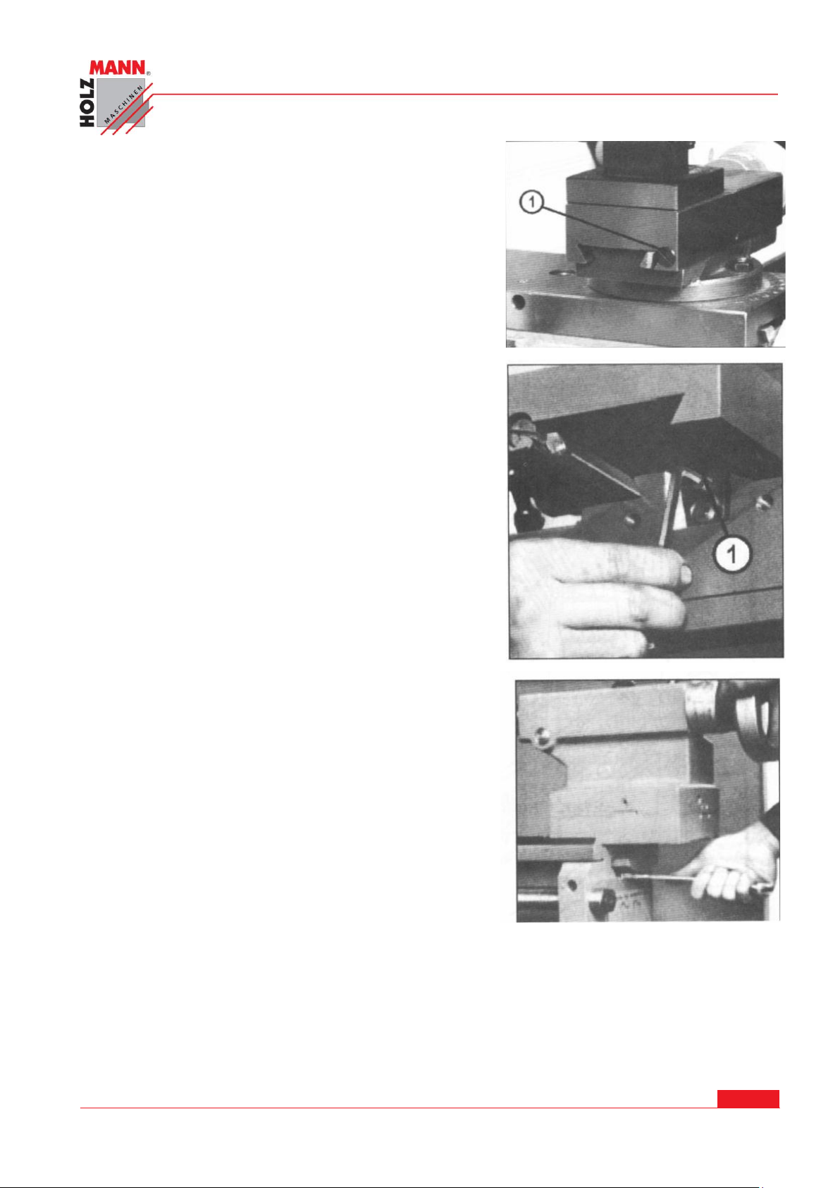
1.36 Compound rest
It is the same procedure as cross slide. To take up for
wear on the compound rest taper gibe strip can adjust
the slotted head screw on the tool post side of the
compound rest by clockwise rotation. The procedure
is to first slacken the similar screw at the opposite
side then re-tighten this after adjustment to clamp the
gibe in its new position.
1.37 Cross slide nut
Provision is made for the elimination of backlash in
the cross slide nut, the procedure for adjustment
being as follows: take off the dust plate which is
mounted on the rear face of saddle groove, turn the
cross feed nut until it reaches the and edge of the
feed rod. Turn the socket head cap screw in a
clockwise direction as required. Care should be taken
to avoid over adjustment, α45°turn at the socket head
capscrew represents approximately 0.125(0.005”)
take up of back lash.
1.38 Tailstock bed clamp
The angular lock position of the bed clamp lever is
adjusted by means of the self-locking hexagon
headed bolt located on the underside of the tailstock
and between the bed ways.
HOLZMANN Maschinen Austria www.holzmann-maschinen.at Seite 39
Metalldrehbank/Metal turning lathe ED1000F
Page 40
CHYBA! POMOCÍ KARTY DOMŮ POUŽIJTE U TEXTU, KTERÝ SE MÁ ZDE ZOBRAZIT, STYL
ÜBERSCHRIFT 1.
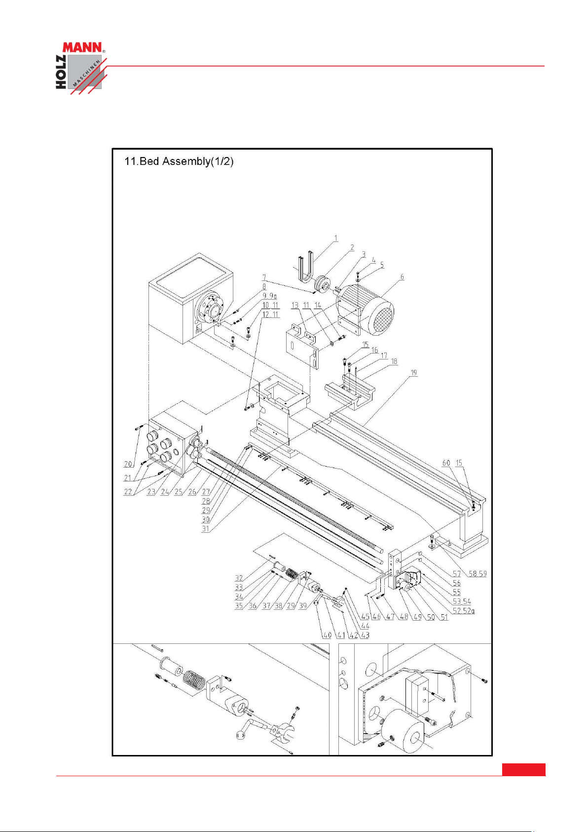
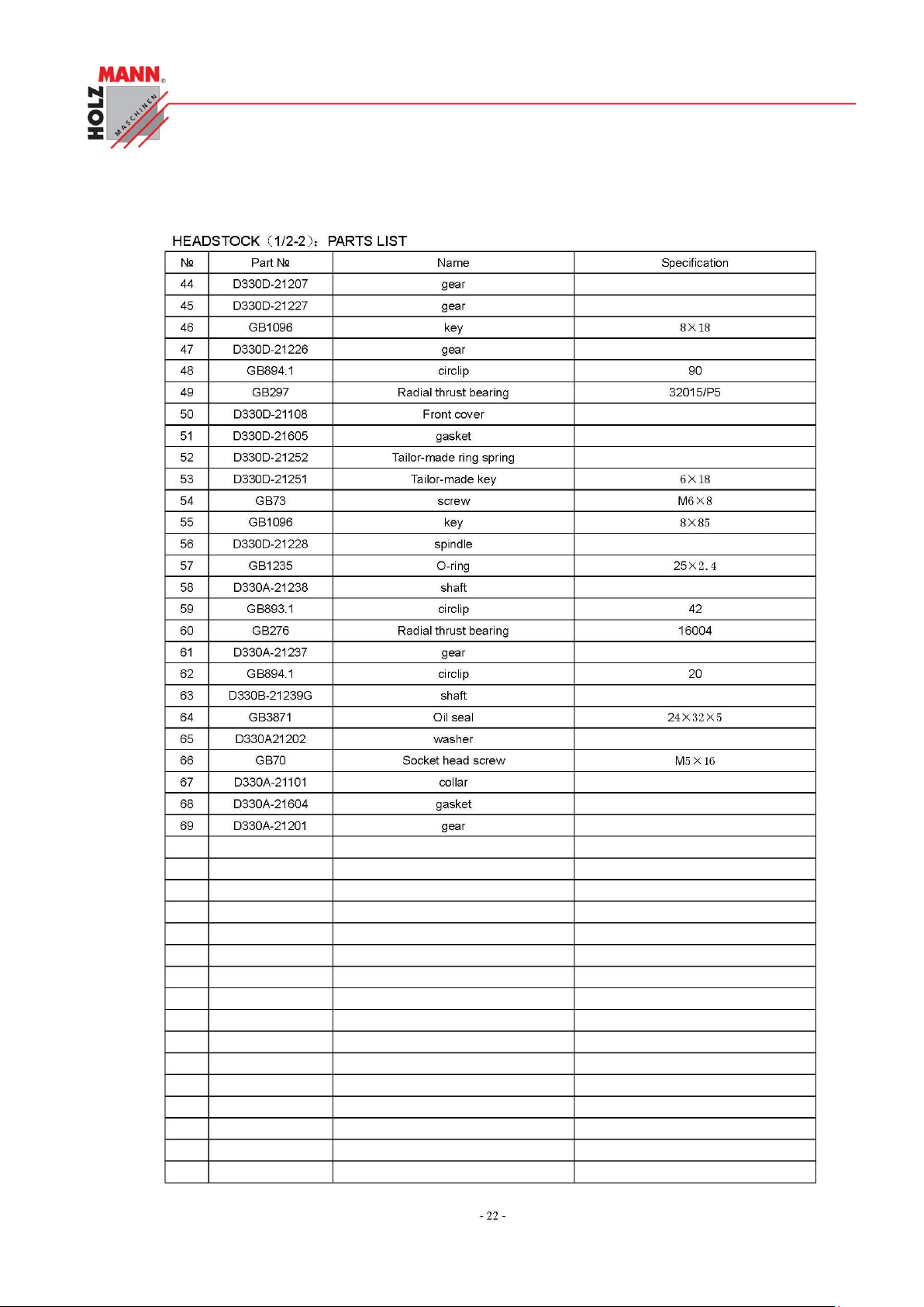
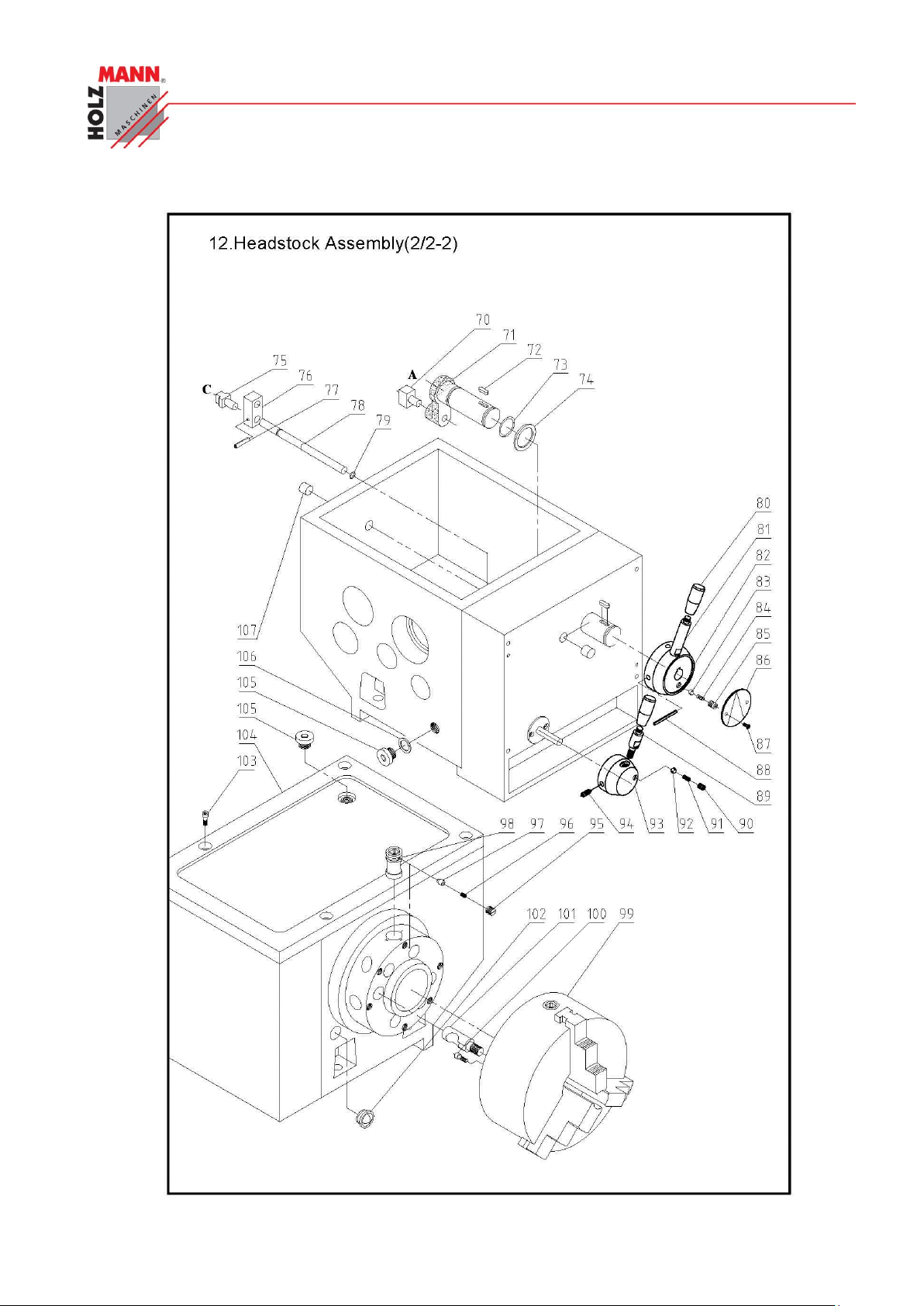
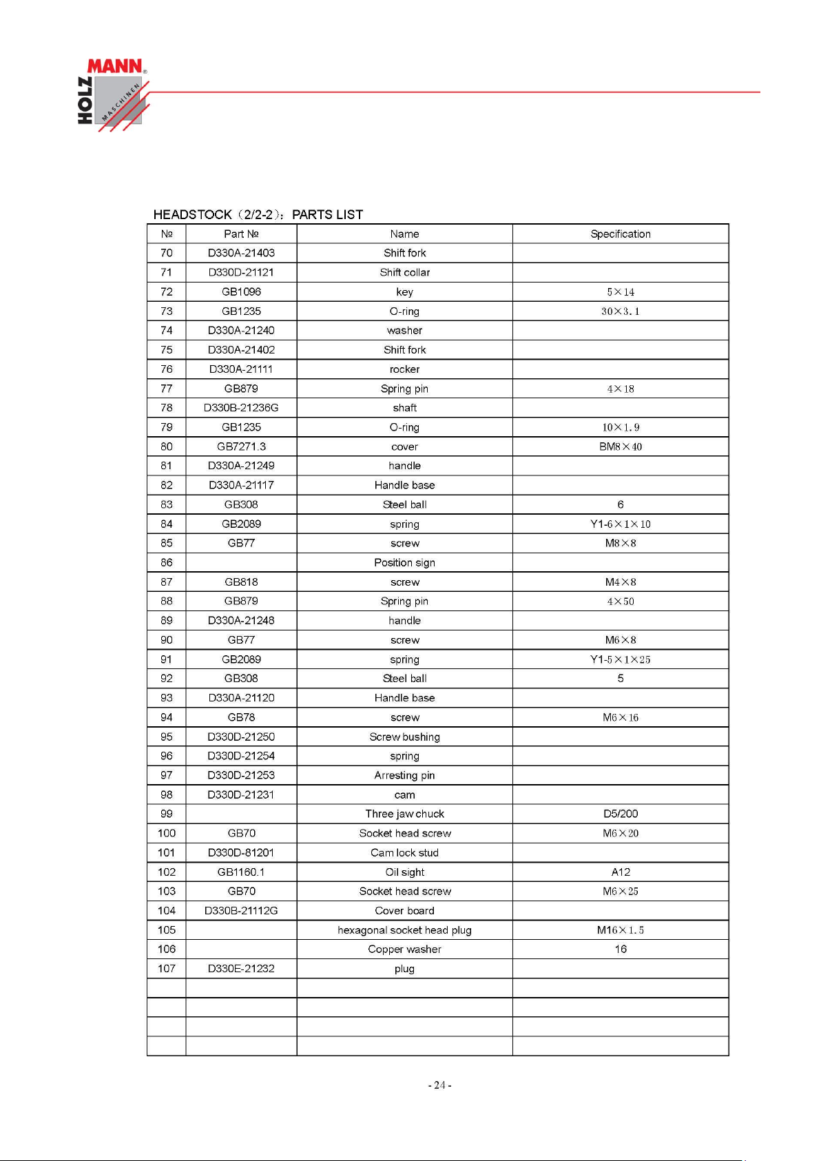
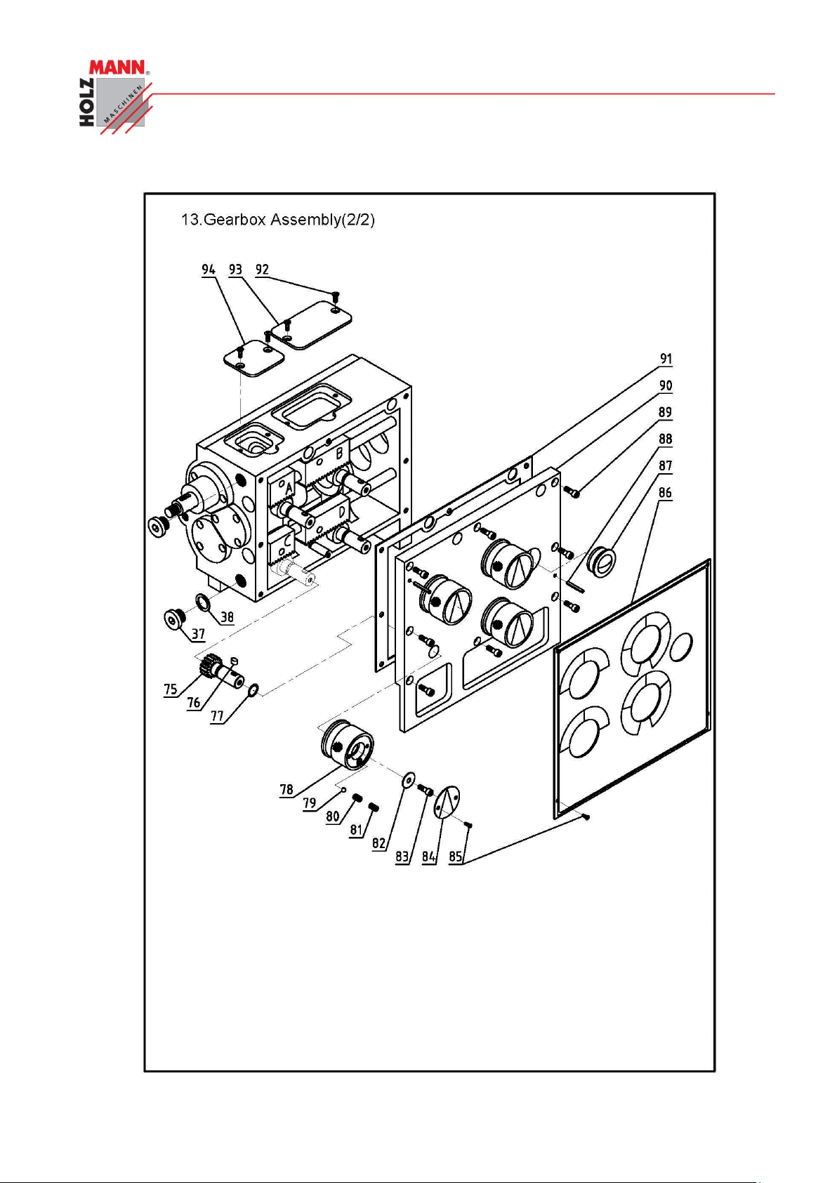
NÁHRADNÍ DÍLY / SPARE PARTS
HOLZMANN Maschinen Austria www.holzmann-maschinen.at Seite 40
Metalldrehbank/Metal turning lathe ED1000F
Page 41
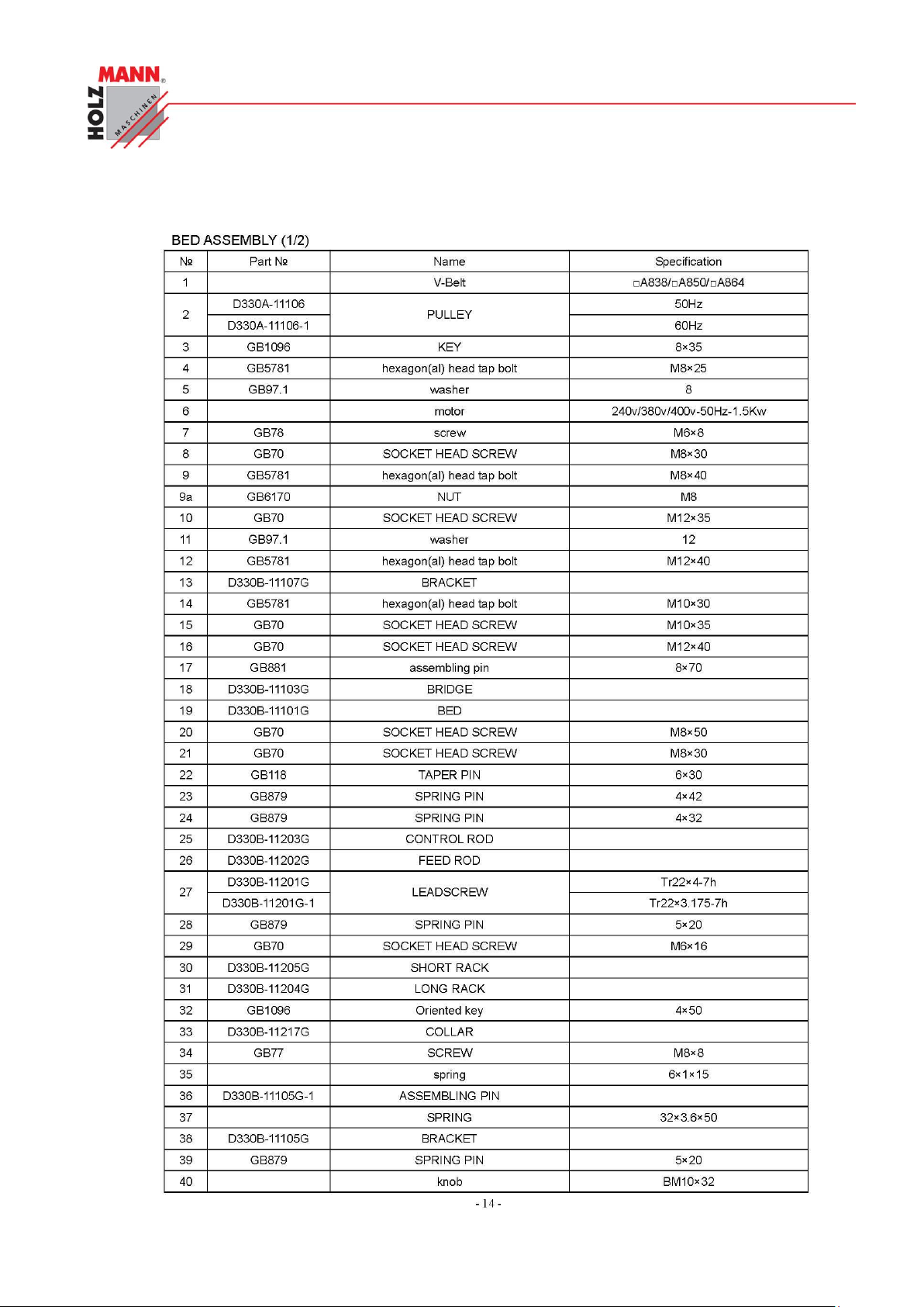
CHYBA! POMOCÍ KARTY DOMŮ POUŽIJTE U TEXTU, KTERÝ SE MÁ ZDE ZOBRAZIT, STYL
ÜBERSCHRIFT 1.
HOLZMANN Maschinen Austria www.holzmann-maschinen.at Seite 41
Metalldrehbank/Metal turning lathe ED1000F
Page 42
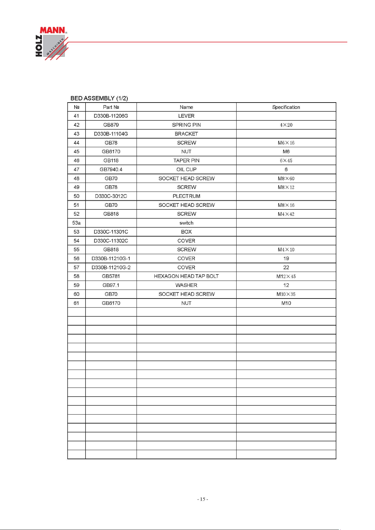
CHYBA! POMOCÍ KARTY DOMŮ POUŽIJTE U TEXTU, KTERÝ SE MÁ ZDE ZOBRAZIT, STYL
ÜBERSCHRIFT 1.
HOLZMANN Maschinen Austria www.holzmann-maschinen.at Seite 42
Metalldrehbank/Metal turning lathe ED1000F
Page 43
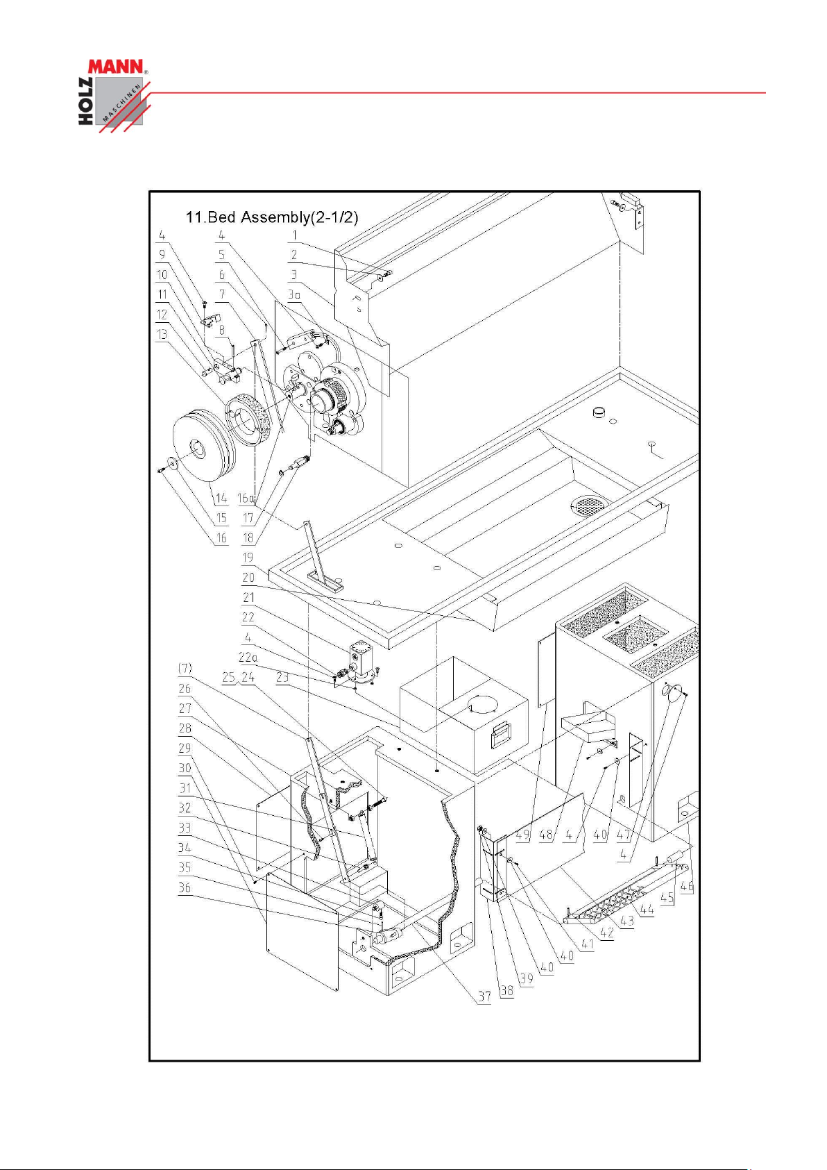
CHYBA! POMOCÍ KARTY DOMŮ POUŽIJTE U TEXTU, KTERÝ SE MÁ ZDE ZOBRAZIT, STYL
ÜBERSCHRIFT 1.
HOLZMANN Maschinen Austria www.holzmann-maschinen.at Seite 43
Metalldrehbank/Metal turning lathe ED1000F
Page 44
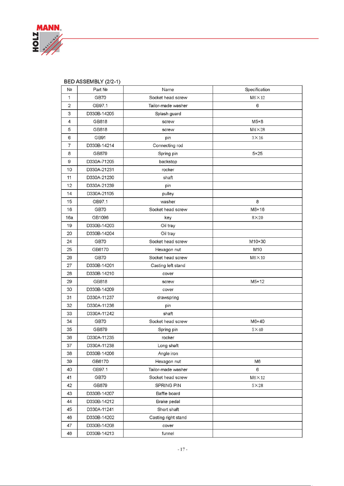
CHYBA! POMOCÍ KARTY DOMŮ POUŽIJTE U TEXTU, KTERÝ SE MÁ ZDE ZOBRAZIT, STYL
ÜBERSCHRIFT 1.
HOLZMANN Maschinen Austria www.holzmann-maschinen.at Seite 44
Metalldrehbank/Metal turning lathe ED1000F
Page 45
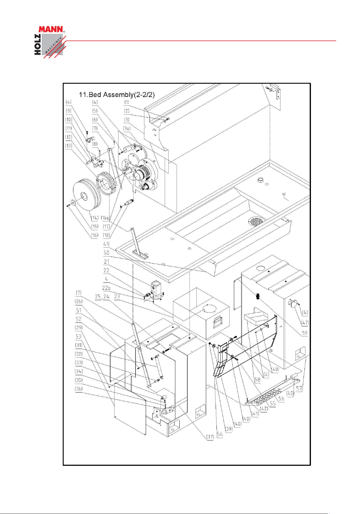
CHYBA! POMOCÍ KARTY DOMŮ POUŽIJTE U TEXTU, KTERÝ SE MÁ ZDE ZOBRAZIT, STYL
ÜBERSCHRIFT 1.
HOLZMANN Maschinen Austria www.holzmann-maschinen.at Seite 45
Metalldrehbank/Metal turning lathe ED1000F
Page 46
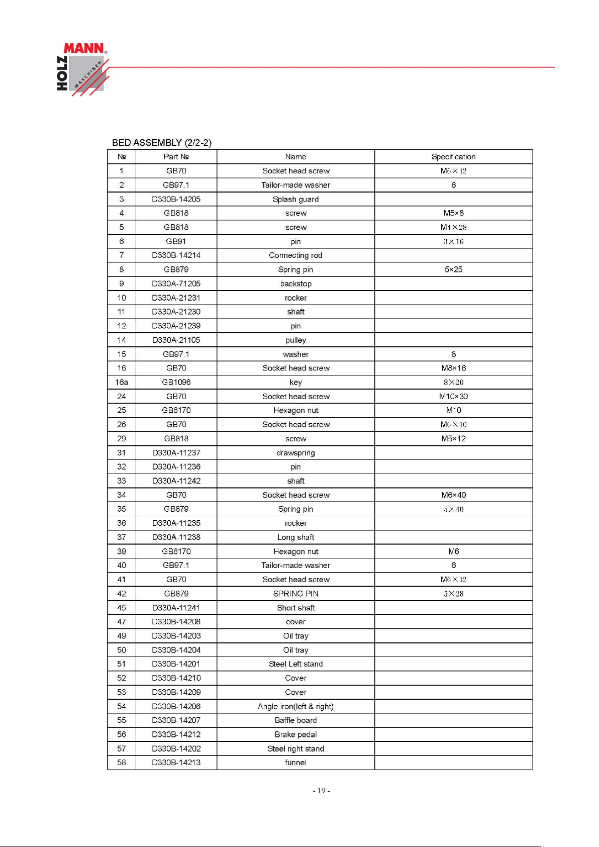
CHYBA! POMOCÍ KARTY DOMŮ POUŽIJTE U TEXTU, KTERÝ SE MÁ ZDE ZOBRAZIT, STYL
ÜBERSCHRIFT 1.
HOLZMANN Maschinen Austria www.holzmann-maschinen.at Seite 46
Metalldrehbank/Metal turning lathe ED1000F
Page 47
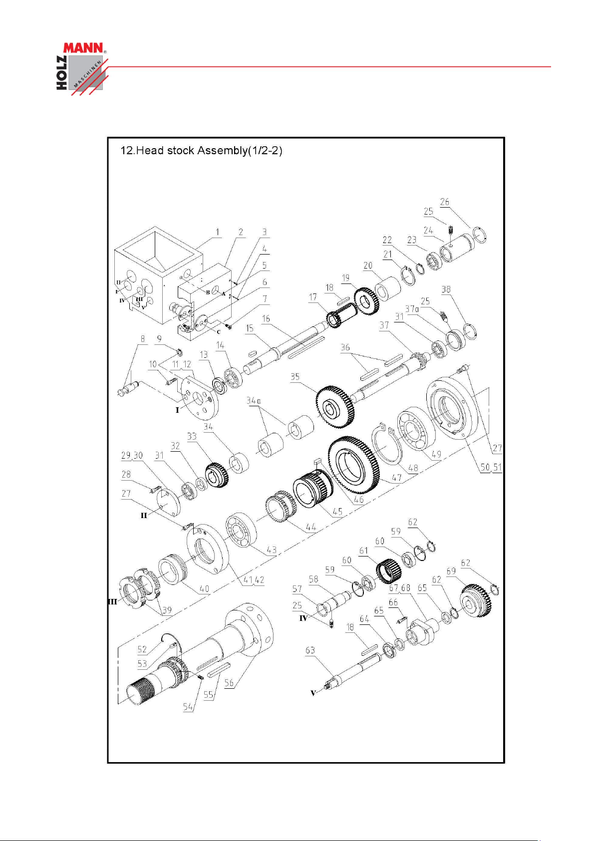
CHYBA! POMOCÍ KARTY DOMŮ POUŽIJTE U TEXTU, KTERÝ SE MÁ ZDE ZOBRAZIT, STYL
ÜBERSCHRIFT 1.
HOLZMANN Maschinen Austria www.holzmann-maschinen.at Seite 47
Metalldrehbank/Metal turning lathe ED1000F
Page 48
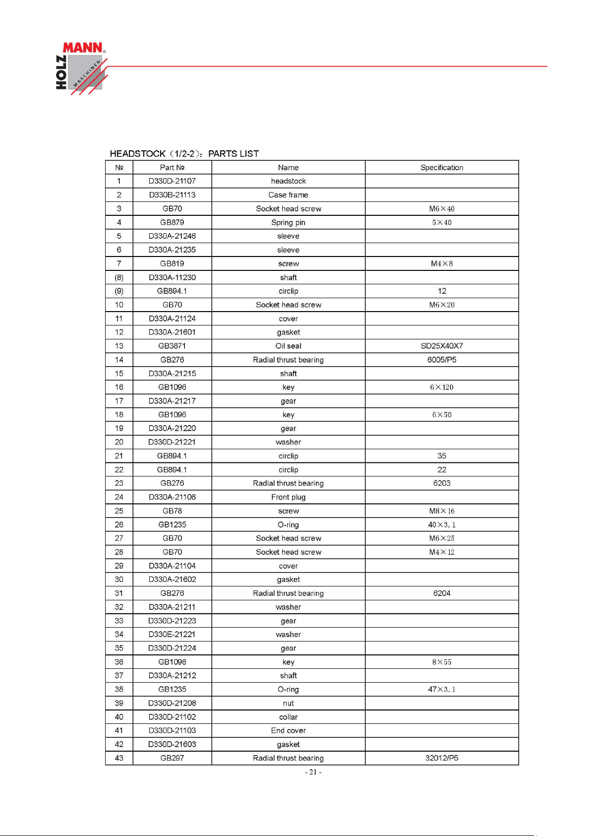
CHYBA! POMOCÍ KARTY DOMŮ POUŽIJTE U TEXTU, KTERÝ SE MÁ ZDE ZOBRAZIT, STYL
ÜBERSCHRIFT 1.
HOLZMANN Maschinen Austria www.holzmann-maschinen.at Seite 48
Metalldrehbank/Metal turning lathe ED1000F
Page 49
CHYBA! POMOCÍ KARTY DOMŮ POUŽIJTE U TEXTU, KTERÝ SE MÁ ZDE ZOBRAZIT, STYL
ÜBERSCHRIFT 1.
HOLZMANN Maschinen Austria www.holzmann-maschinen.at Seite 49
Metalldrehbank/Metal turning lathe ED1000F
Page 50
CHYBA! POMOCÍ KARTY DOMŮ POUŽIJTE U TEXTU, KTERÝ SE MÁ ZDE ZOBRAZIT, STYL
ÜBERSCHRIFT 1.
HOLZMANN Maschinen Austria www.holzmann-maschinen.at Seite 50
Metalldrehbank/Metal turning lathe ED1000F
Page 51
CHYBA! POMOCÍ KARTY DOMŮ POUŽIJTE U TEXTU, KTERÝ SE MÁ ZDE ZOBRAZIT, STYL
ÜBERSCHRIFT 1.
HOLZMANN Maschinen Austria www.holzmann-maschinen.at Seite 51
Metalldrehbank/Metal turning lathe ED1000F
Page 52

CHYBA! POMOCÍ KARTY DOMŮ POUŽIJTE U TEXTU, KTERÝ SE MÁ ZDE ZOBRAZIT, STYL
ÜBERSCHRIFT 1.
HOLZMANN Maschinen Austria www.holzmann-maschinen.at Seite 52
Metalldrehbank/Metal turning lathe ED1000F
Page 53
CHYBA! POMOCÍ KARTY DOMŮ POUŽIJTE U TEXTU, KTERÝ SE MÁ ZDE ZOBRAZIT, STYL
ÜBERSCHRIFT 1.
HOLZMANN Maschinen Austria www.holzmann-maschinen.at Seite 53
Metalldrehbank/Metal turning lathe ED1000F
Page 54
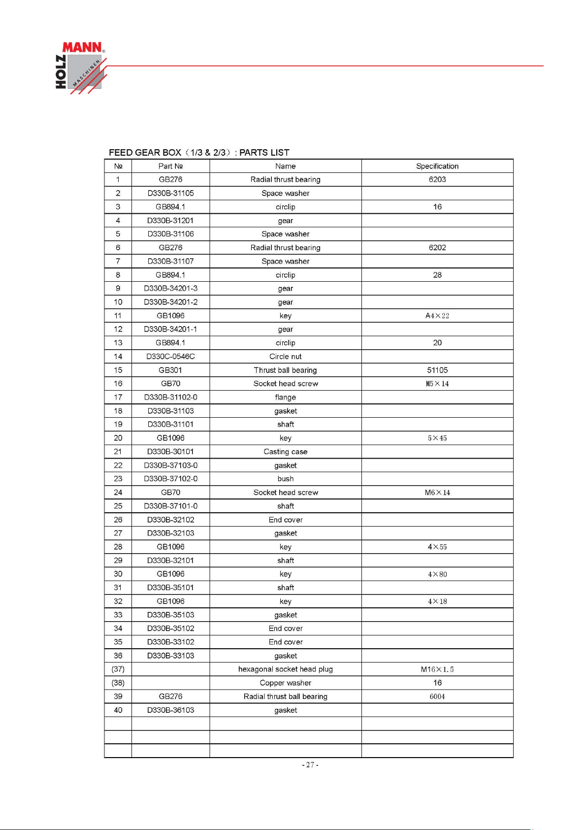
CHYBA! POMOCÍ KARTY DOMŮ POUŽIJTE U TEXTU, KTERÝ SE MÁ ZDE ZOBRAZIT, STYL
ÜBERSCHRIFT 1.
HOLZMANN Maschinen Austria www.holzmann-maschinen.at Seite 54
Metalldrehbank/Metal turning lathe ED1000F
Page 55
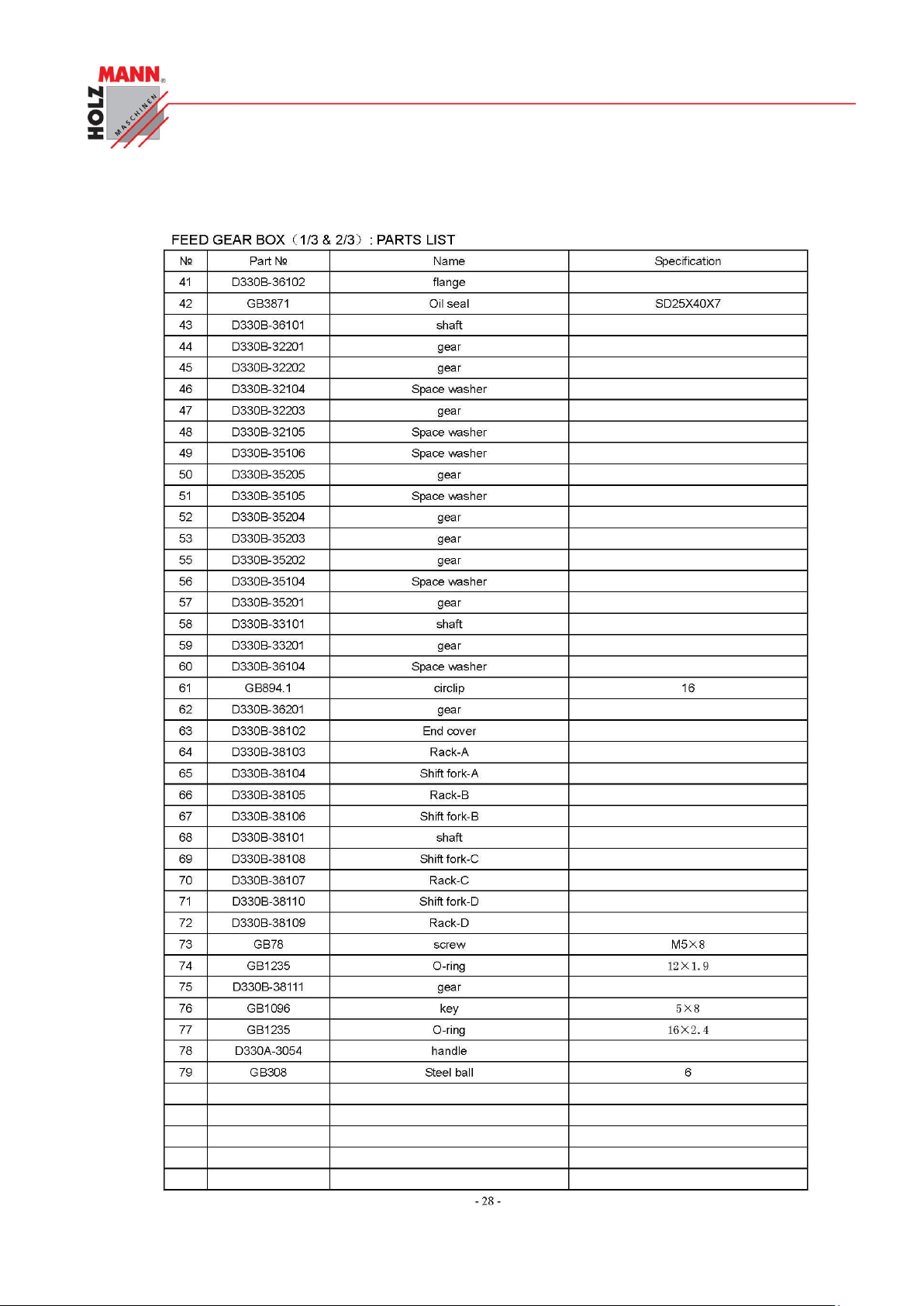
CHYBA! POMOCÍ KARTY DOMŮ POUŽIJTE U TEXTU, KTERÝ SE MÁ ZDE ZOBRAZIT, STYL
ÜBERSCHRIFT 1.
HOLZMANN Maschinen Austria www.holzmann-maschinen.at Seite 55
Metalldrehbank/Metal turning lathe ED1000F
Page 56
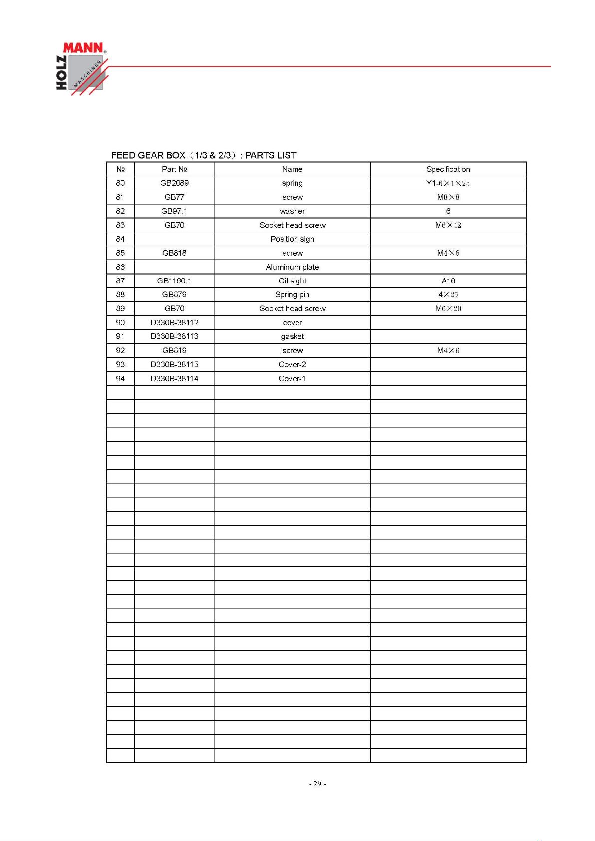
CHYBA! POMOCÍ KARTY DOMŮ POUŽIJTE U TEXTU, KTERÝ SE MÁ ZDE ZOBRAZIT, STYL
ÜBERSCHRIFT 1.
HOLZMANN Maschinen Austria www.holzmann-maschinen.at Seite 56
Metalldrehbank/Metal turning lathe ED1000F
Page 57
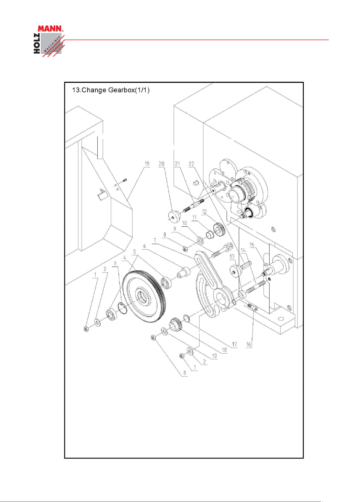
CHYBA! POMOCÍ KARTY DOMŮ POUŽIJTE U TEXTU, KTERÝ SE MÁ ZDE ZOBRAZIT, STYL
ÜBERSCHRIFT 1.
HOLZMANN Maschinen Austria www.holzmann-maschinen.at Seite 57
Metalldrehbank/Metal turning lathe ED1000F
Page 58
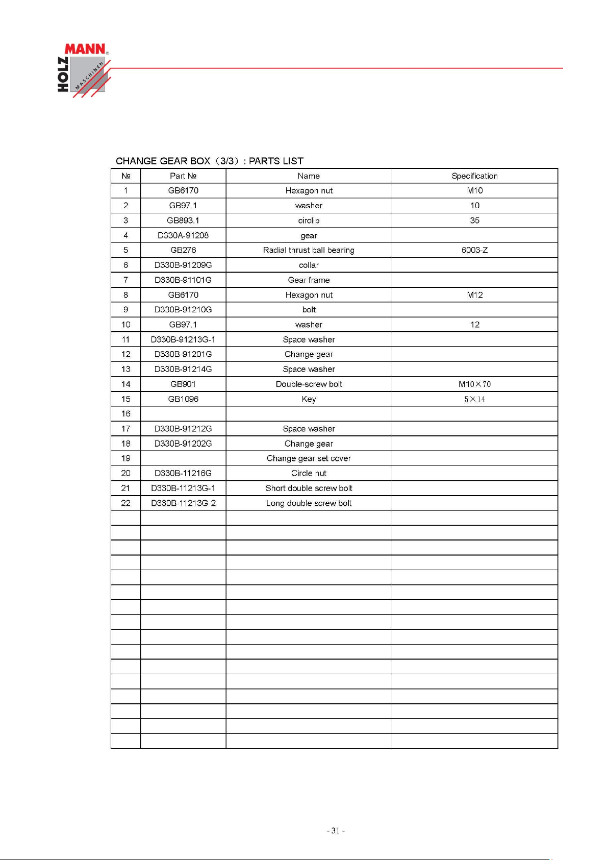
CHYBA! POMOCÍ KARTY DOMŮ POUŽIJTE U TEXTU, KTERÝ SE MÁ ZDE ZOBRAZIT, STYL
ÜBERSCHRIFT 1.
HOLZMANN Maschinen Austria www.holzmann-maschinen.at Seite 58
Metalldrehbank/Metal turning lathe ED1000F
Page 59
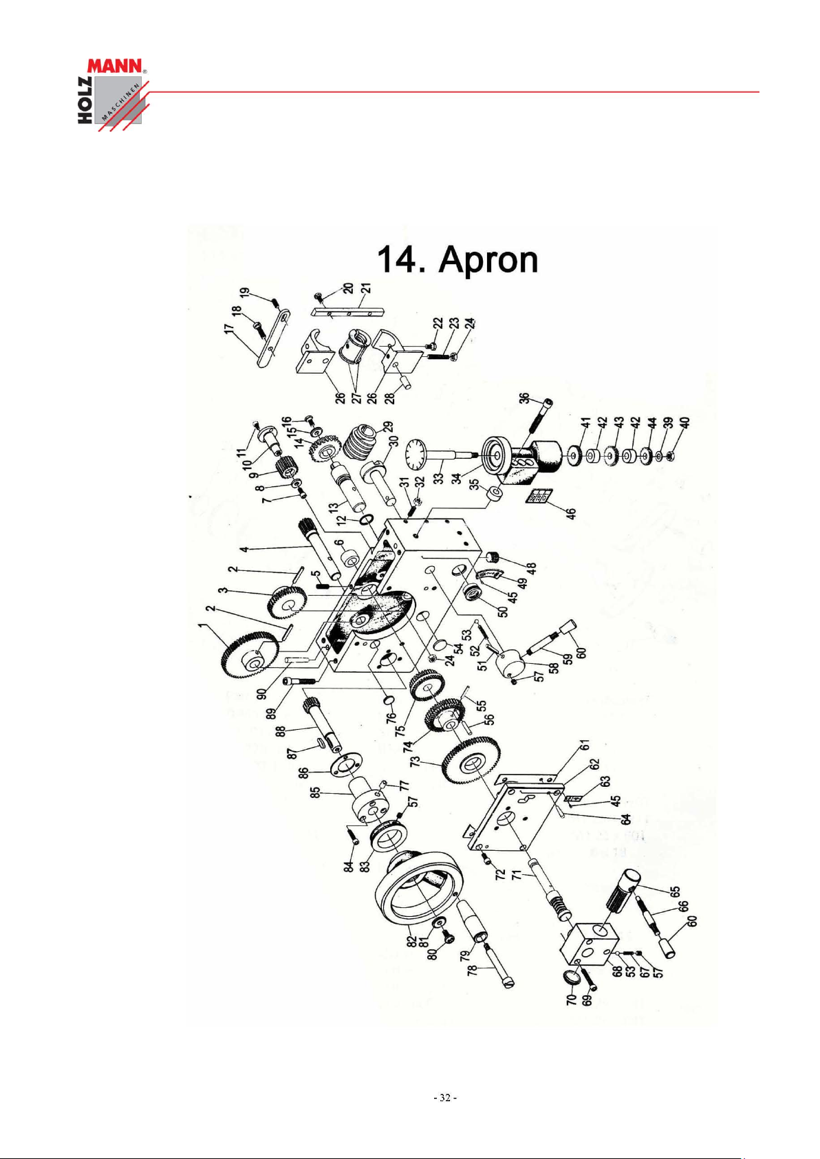
CHYBA! POMOCÍ KARTY DOMŮ POUŽIJTE U TEXTU, KTERÝ SE MÁ ZDE ZOBRAZIT, STYL
ÜBERSCHRIFT 1.
HOLZMANN Maschinen Austria www.holzmann-maschinen.at Seite 59
Metalldrehbank/Metal turning lathe ED1000F
Page 60
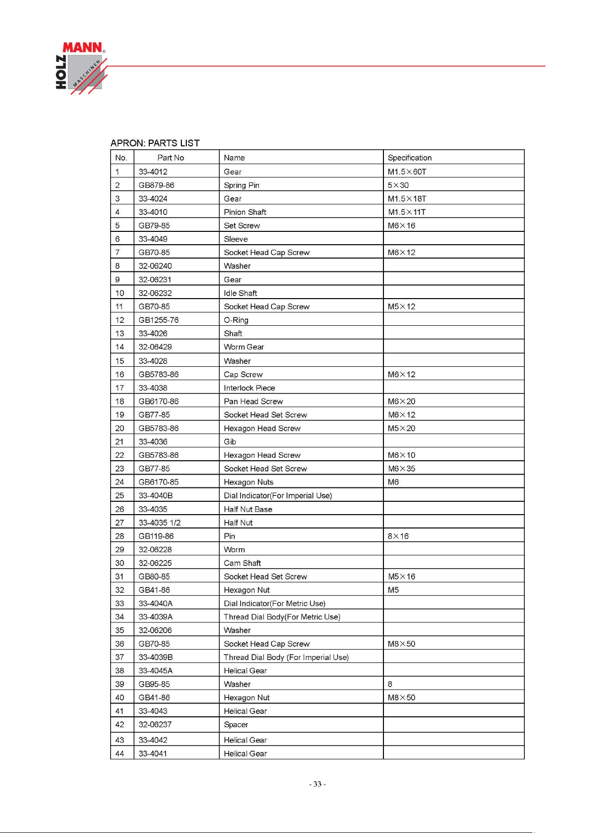
CHYBA! POMOCÍ KARTY DOMŮ POUŽIJTE U TEXTU, KTERÝ SE MÁ ZDE ZOBRAZIT, STYL
ÜBERSCHRIFT 1.
HOLZMANN Maschinen Austria www.holzmann-maschinen.at Seite 60
Metalldrehbank/Metal turning lathe ED1000F
Page 61
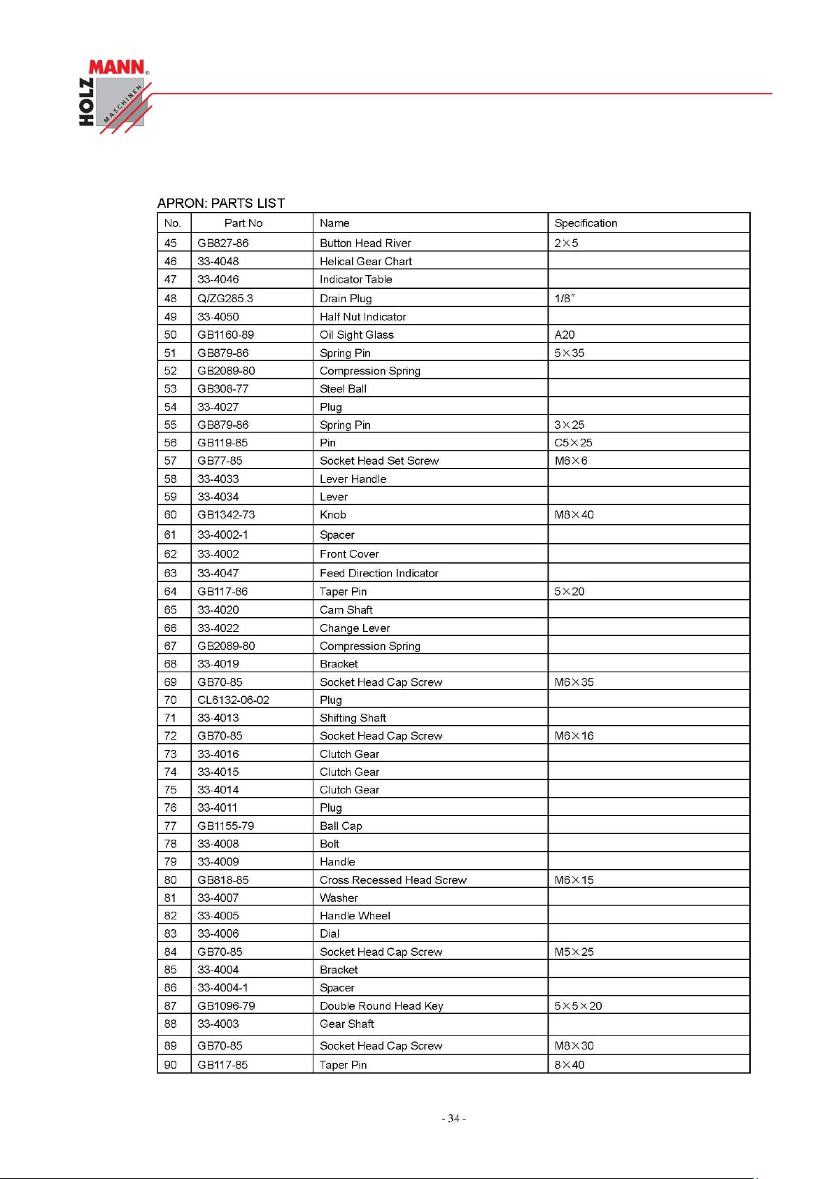
CHYBA! POMOCÍ KARTY DOMŮ POUŽIJTE U TEXTU, KTERÝ SE MÁ ZDE ZOBRAZIT, STYL
ÜBERSCHRIFT 1.
HOLZMANN Maschinen Austria www.holzmann-maschinen.at Seite 61
Metalldrehbank/Metal turning lathe ED1000F
Page 62
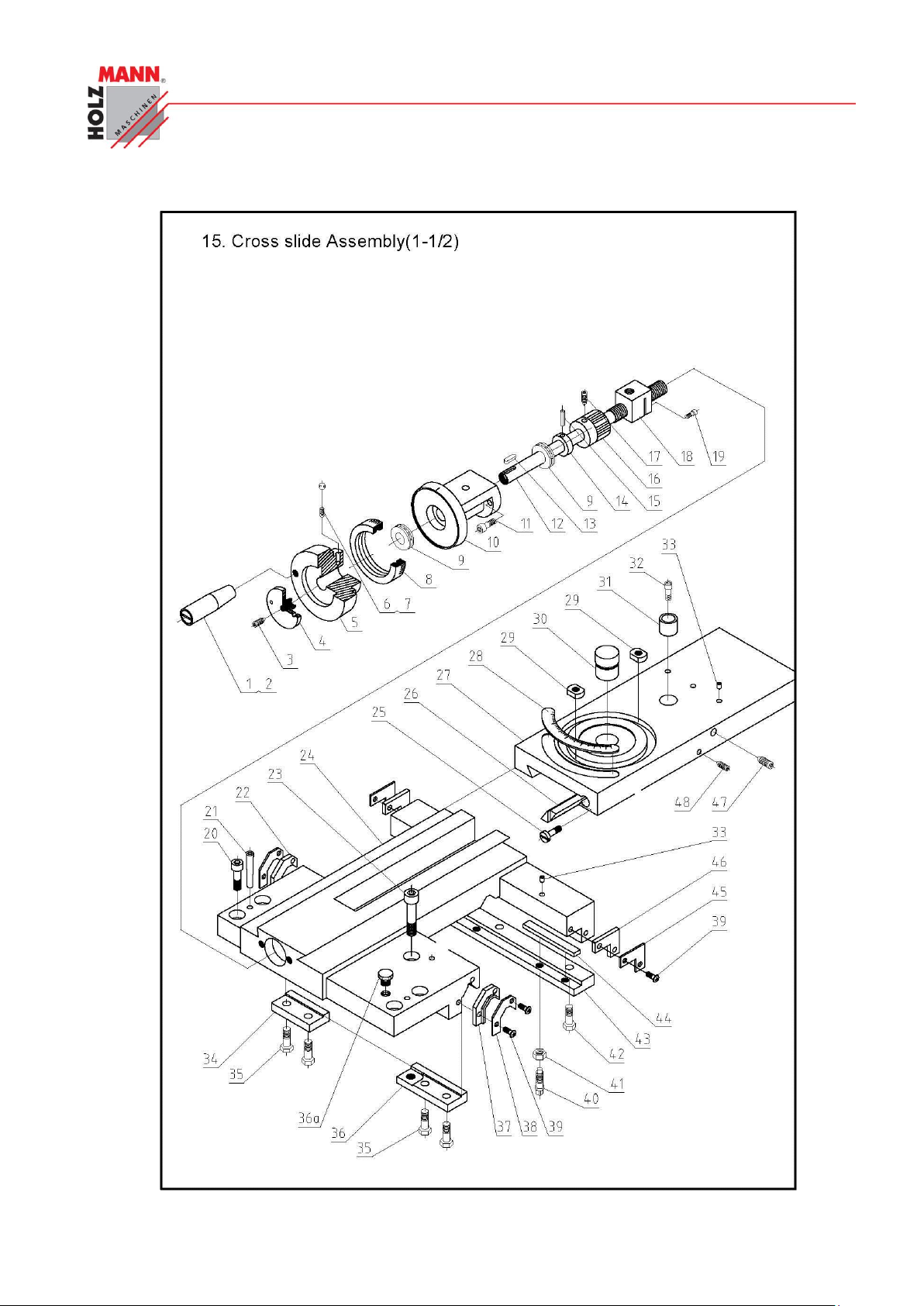
CHYBA! POMOCÍ KARTY DOMŮ POUŽIJTE U TEXTU, KTERÝ SE MÁ ZDE ZOBRAZIT, STYL
ÜBERSCHRIFT 1.
HOLZMANN Maschinen Austria www.holzmann-maschinen.at Seite 62
Metalldrehbank/Metal turning lathe ED1000F
Page 63
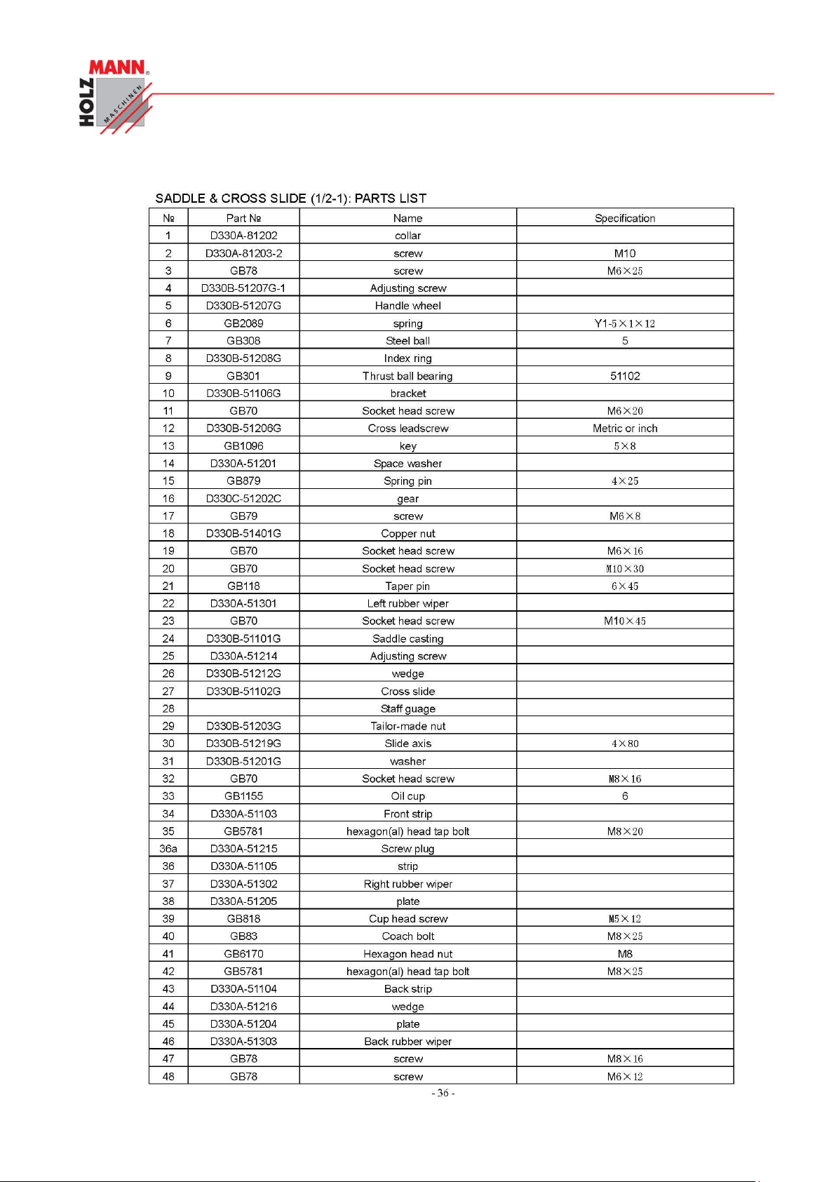
CHYBA! POMOCÍ KARTY DOMŮ POUŽIJTE U TEXTU, KTERÝ SE MÁ ZDE ZOBRAZIT, STYL
ÜBERSCHRIFT 1.
HOLZMANN Maschinen Austria www.holzmann-maschinen.at Seite 63
Metalldrehbank/Metal turning lathe ED1000F
Page 64
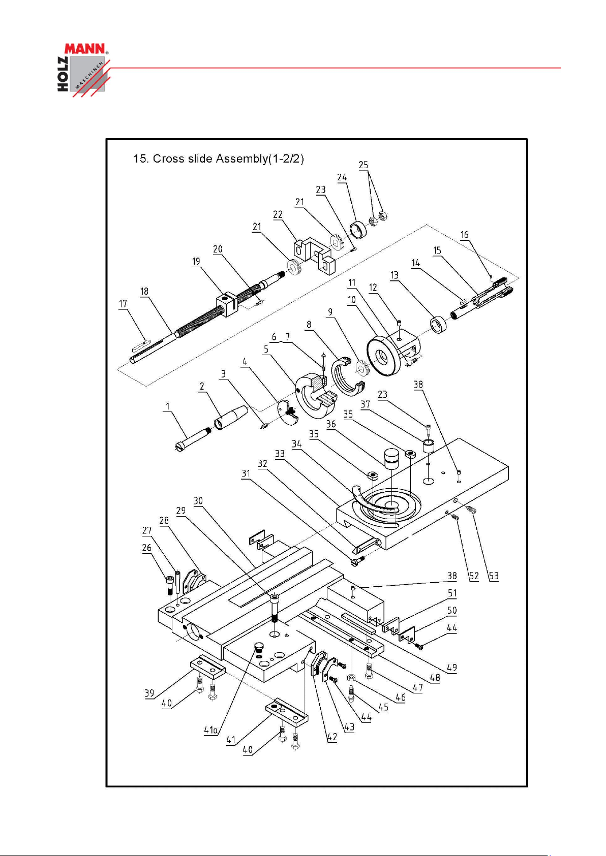
CHYBA! POMOCÍ KARTY DOMŮ POUŽIJTE U TEXTU, KTERÝ SE MÁ ZDE ZOBRAZIT, STYL
ÜBERSCHRIFT 1.
HOLZMANN Maschinen Austria www.holzmann-maschinen.at Seite 64
Metalldrehbank/Metal turning lathe ED1000F
Page 65
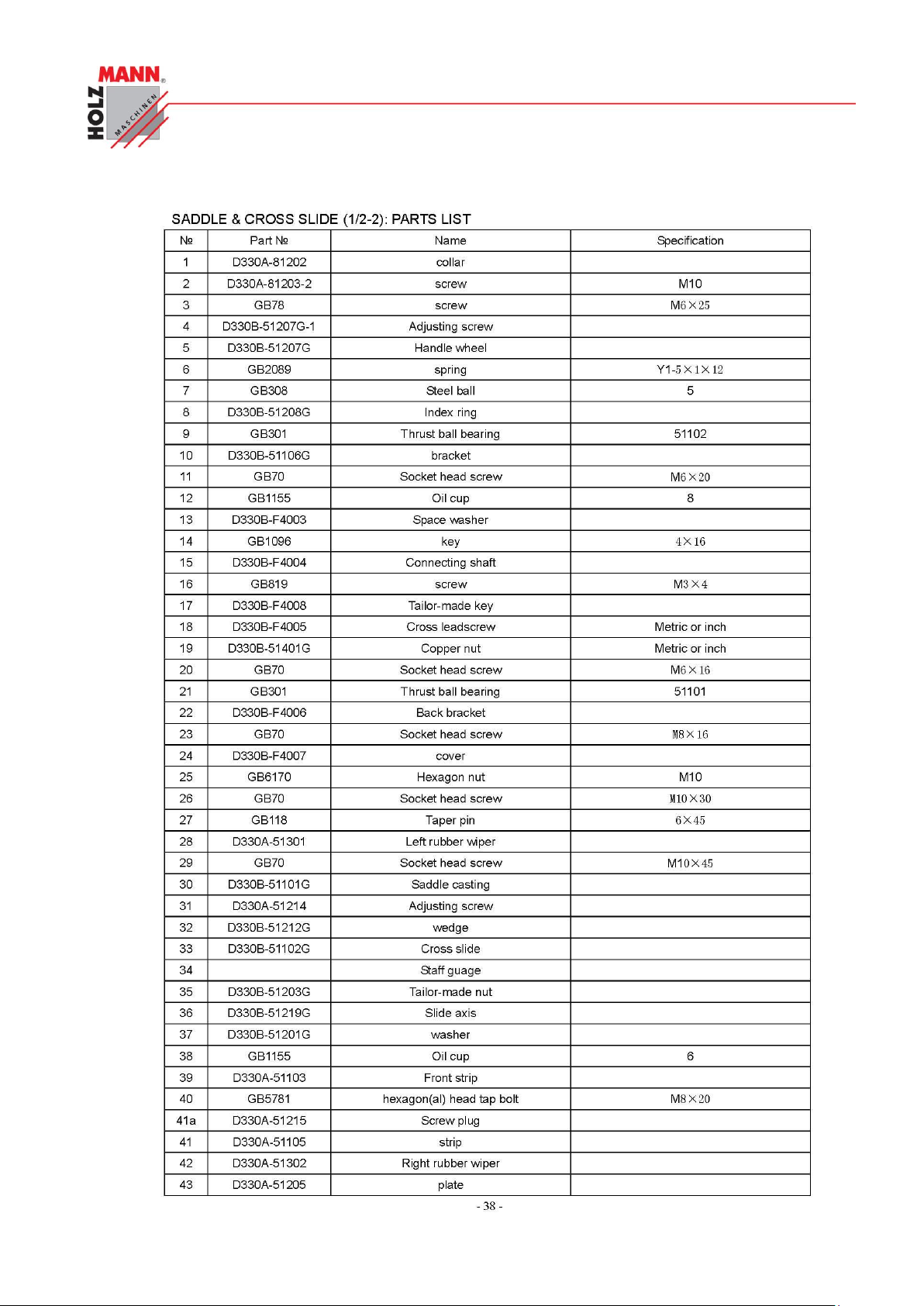
CHYBA! POMOCÍ KARTY DOMŮ POUŽIJTE U TEXTU, KTERÝ SE MÁ ZDE ZOBRAZIT, STYL
ÜBERSCHRIFT 1.
HOLZMANN Maschinen Austria www.holzmann-maschinen.at Seite 65
Metalldrehbank/Metal turning lathe ED1000F
Page 66
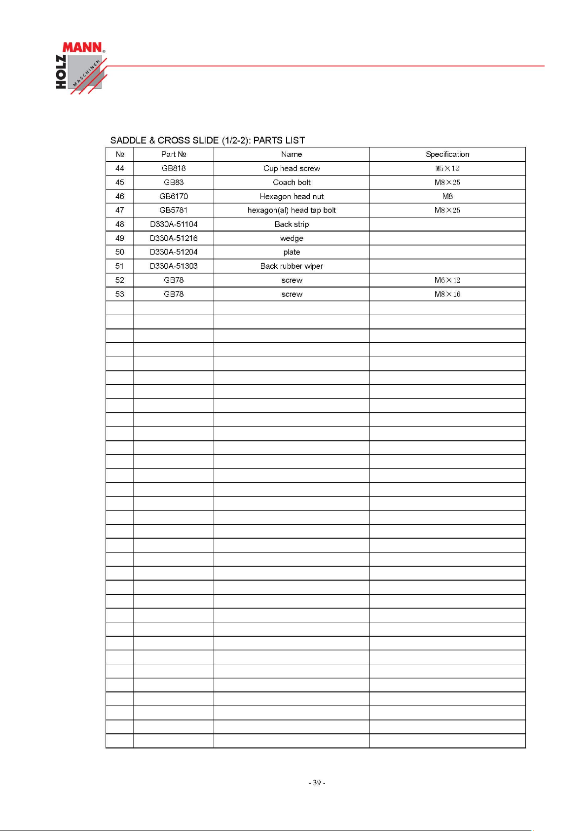
CHYBA! POMOCÍ KARTY DOMŮ POUŽIJTE U TEXTU, KTERÝ SE MÁ ZDE ZOBRAZIT, STYL
ÜBERSCHRIFT 1.
HOLZMANN Maschinen Austria www.holzmann-maschinen.at Seite 66
Metalldrehbank/Metal turning lathe ED1000F
Page 67
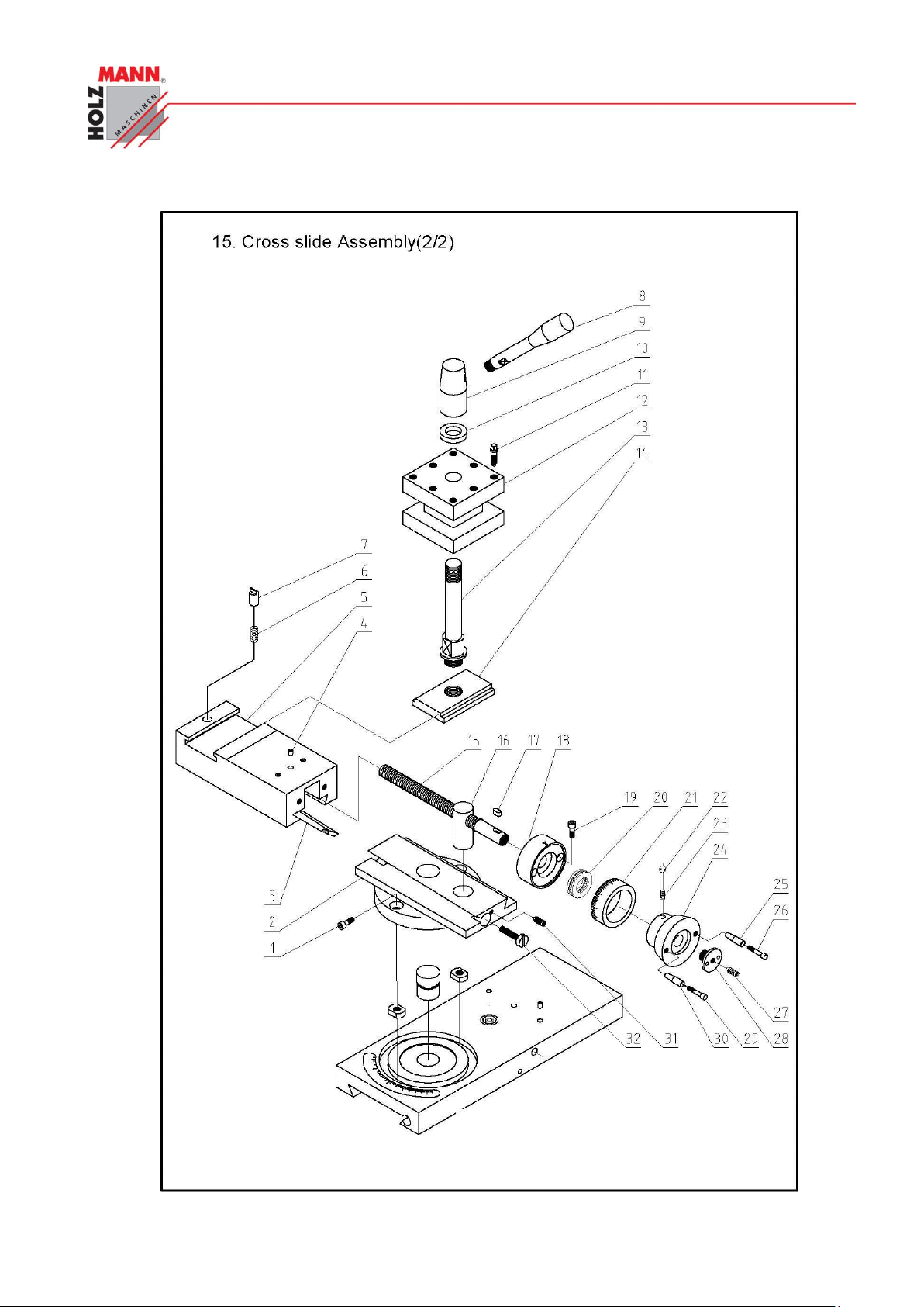
CHYBA! POMOCÍ KARTY DOMŮ POUŽIJTE U TEXTU, KTERÝ SE MÁ ZDE ZOBRAZIT, STYL
ÜBERSCHRIFT 1.
HOLZMANN Maschinen Austria www.holzmann-maschinen.at Seite 67
Metalldrehbank/Metal turning lathe ED1000F
Page 68
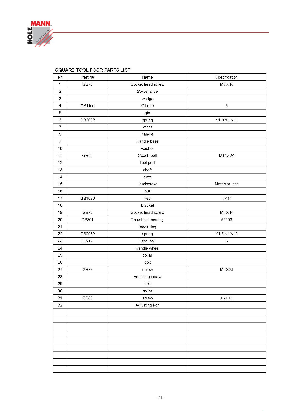
CHYBA! POMOCÍ KARTY DOMŮ POUŽIJTE U TEXTU, KTERÝ SE MÁ ZDE ZOBRAZIT, STYL
ÜBERSCHRIFT 1.
HOLZMANN Maschinen Austria www.holzmann-maschinen.at Seite 68
Metalldrehbank/Metal turning lathe ED1000F
Page 69
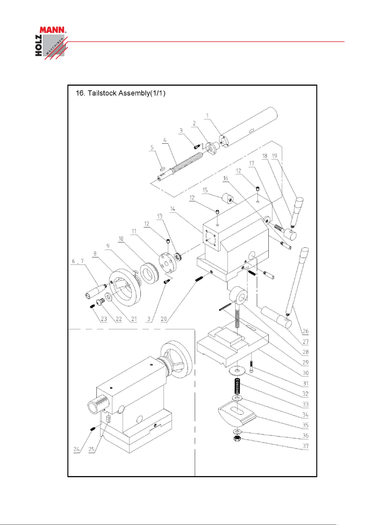
CHYBA! POMOCÍ KARTY DOMŮ POUŽIJTE U TEXTU, KTERÝ SE MÁ ZDE ZOBRAZIT, STYL
ÜBERSCHRIFT 1.
HOLZMANN Maschinen Austria www.holzmann-maschinen.at Seite 69
Metalldrehbank/Metal turning lathe ED1000F
Page 70
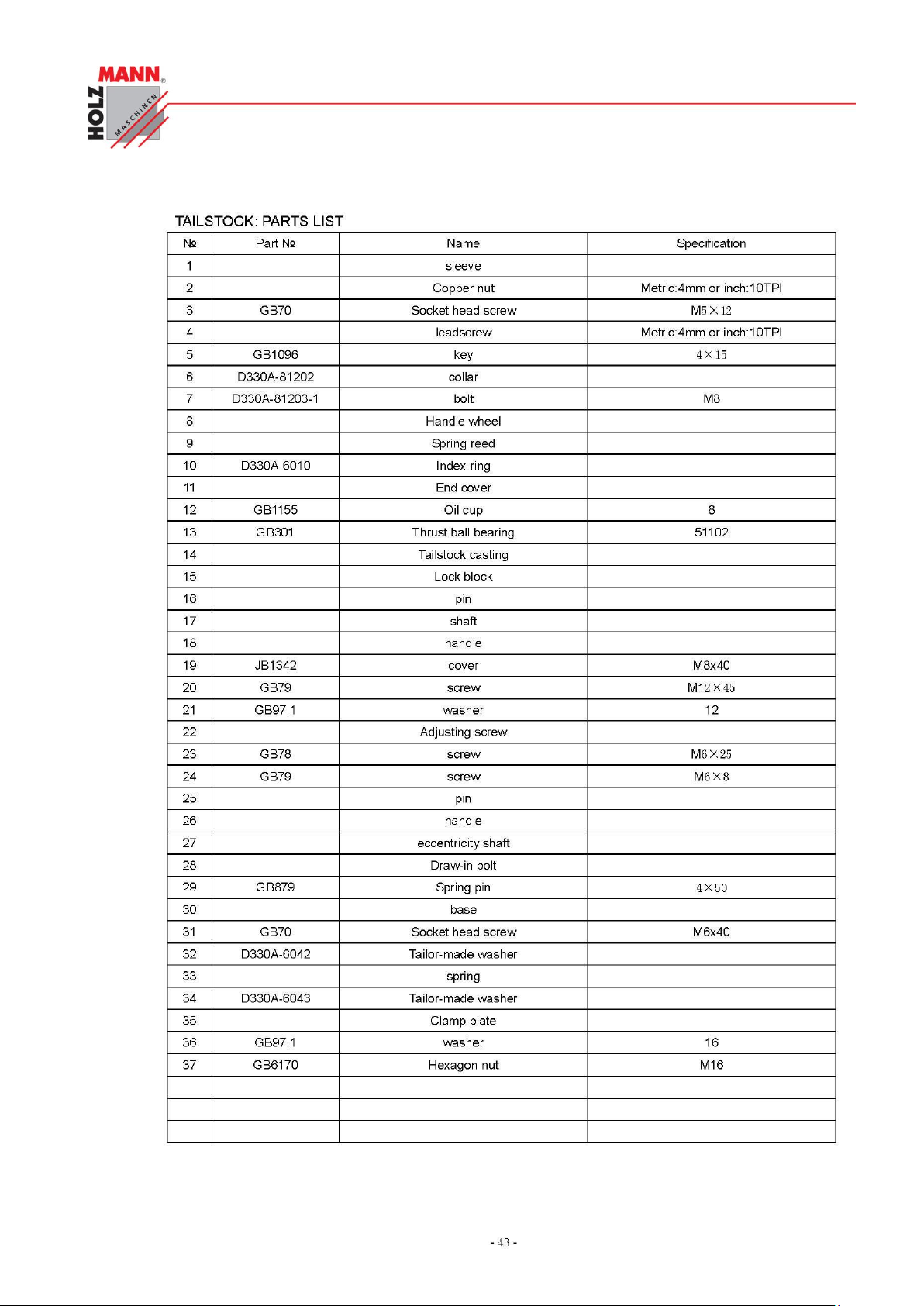
CHYBA! POMOCÍ KARTY DOMŮ POUŽIJTE U TEXTU, KTERÝ SE MÁ ZDE ZOBRAZIT, STYL
ÜBERSCHRIFT 1.
HOLZMANN Maschinen Austria www.holzmann-maschinen.at Seite 70
Metalldrehbank/Metal turning lathe ED1000F
Page 71
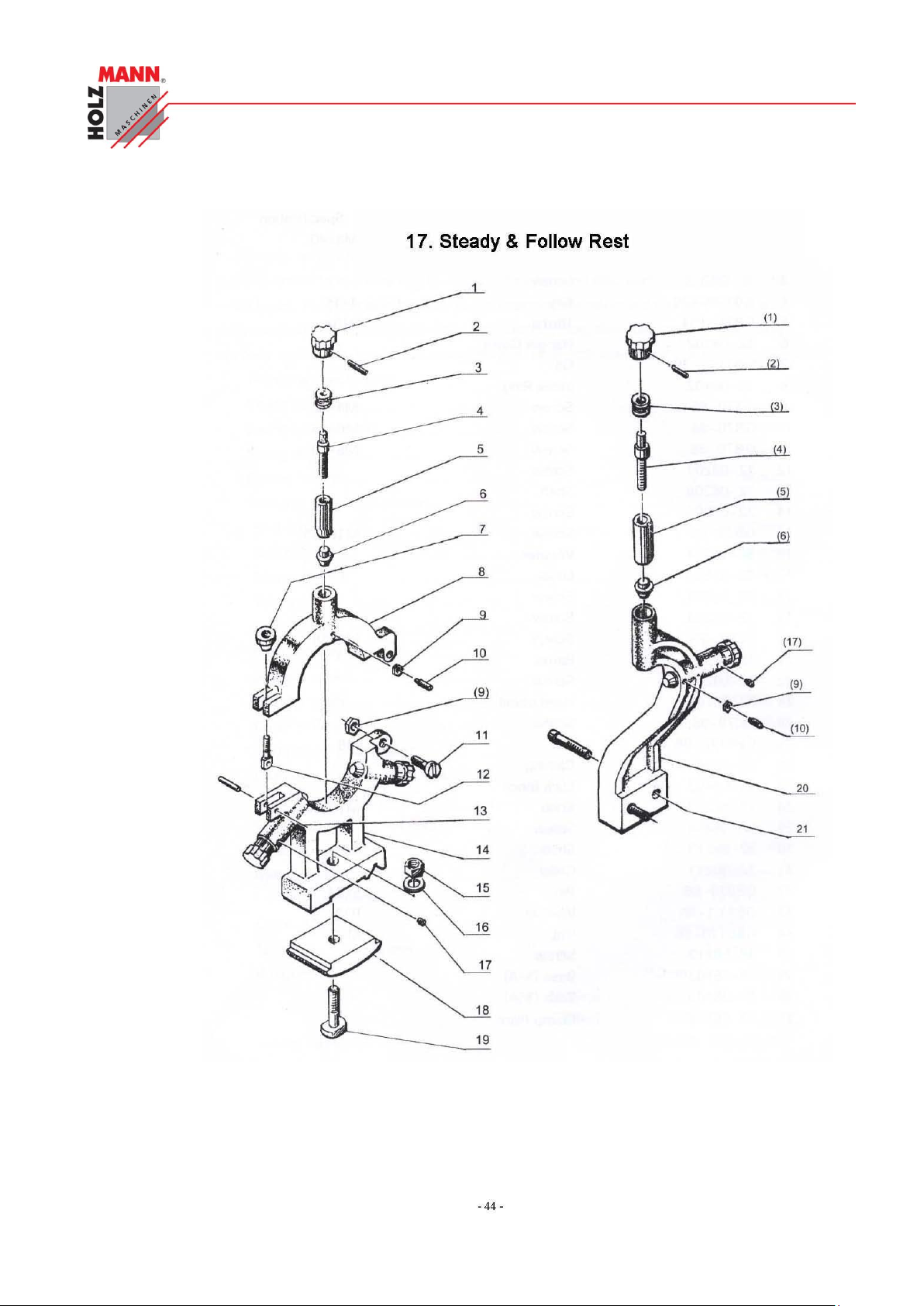
CHYBA! POMOCÍ KARTY DOMŮ POUŽIJTE U TEXTU, KTERÝ SE MÁ ZDE ZOBRAZIT, STYL
ÜBERSCHRIFT 1.
HOLZMANN Maschinen Austria www.holzmann-maschinen.at Seite 71
Metalldrehbank/Metal turning lathe ED1000F
Page 72
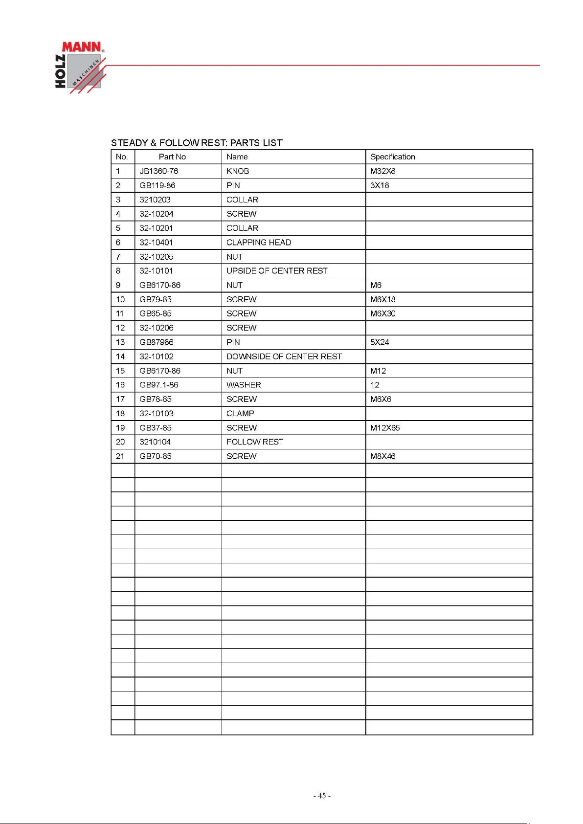
CHYBA! POMOCÍ KARTY DOMŮ POUŽIJTE U TEXTU, KTERÝ SE MÁ ZDE ZOBRAZIT, STYL
ÜBERSCHRIFT 1.
HOLZMANN Maschinen Austria www.holzmann-maschinen.at Seite 72
Metalldrehbank/Metal turning lathe ED1000F
Page 73
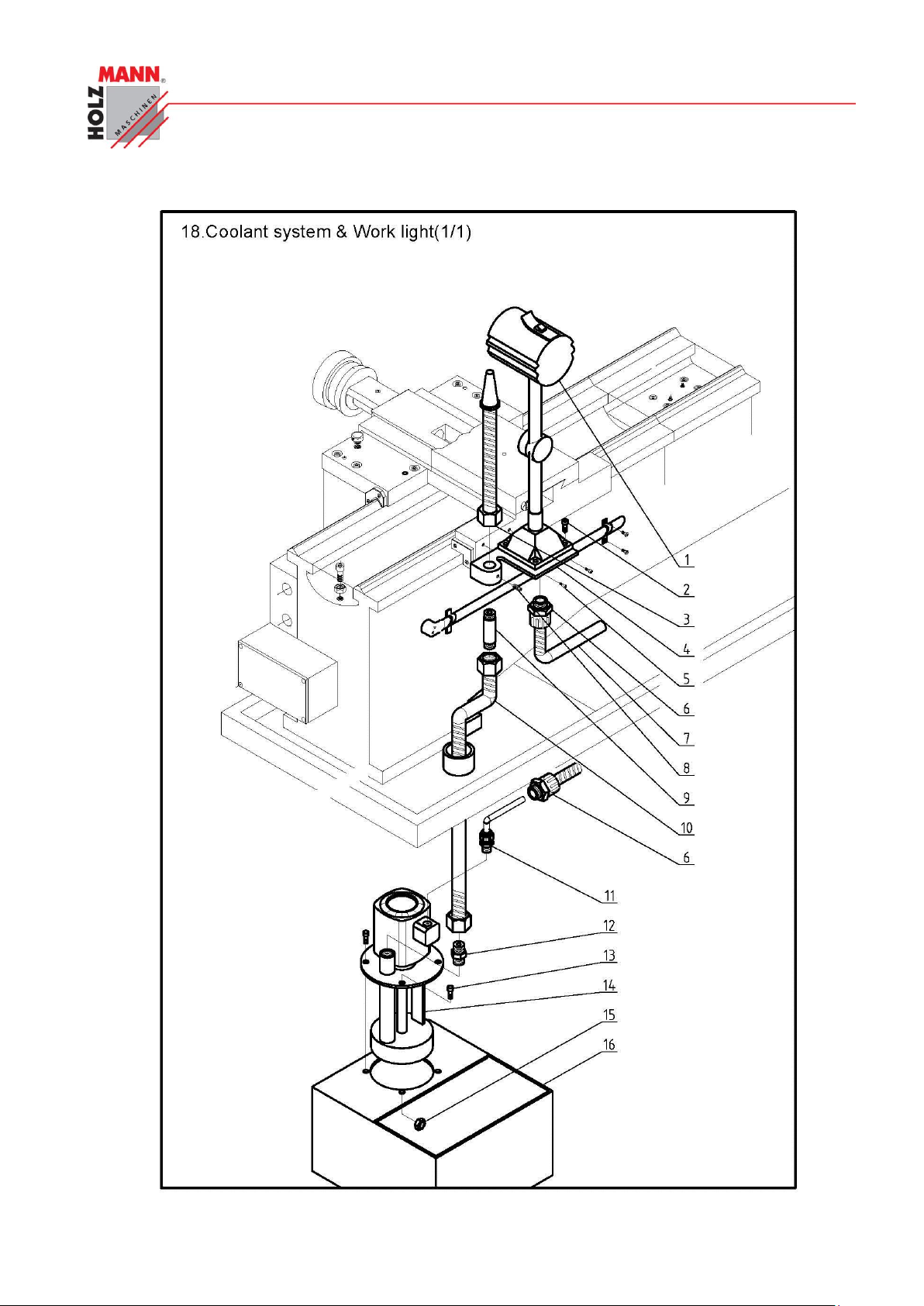
CHYBA! POMOCÍ KARTY DOMŮ POUŽIJTE U TEXTU, KTERÝ SE MÁ ZDE ZOBRAZIT, STYL
ÜBERSCHRIFT 1.
HOLZMANN Maschinen Austria www.holzmann-maschinen.at Seite 73
Metalldrehbank/Metal turning lathe ED1000F
Page 74
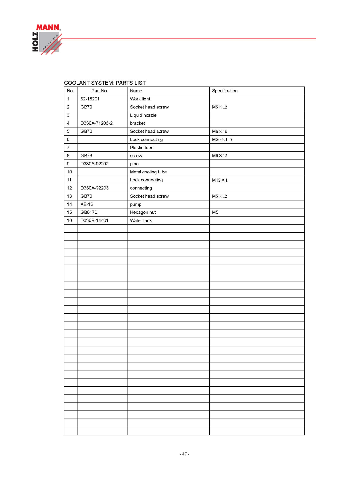
CHYBA! POMOCÍ KARTY DOMŮ POUŽIJTE U TEXTU, KTERÝ SE MÁ ZDE ZOBRAZIT, STYL
ÜBERSCHRIFT 1.
HOLZMANN Maschinen Austria www.holzmann-maschinen.at Seite 74
Metalldrehbank/Metal turning lathe ED1000F
Page 75
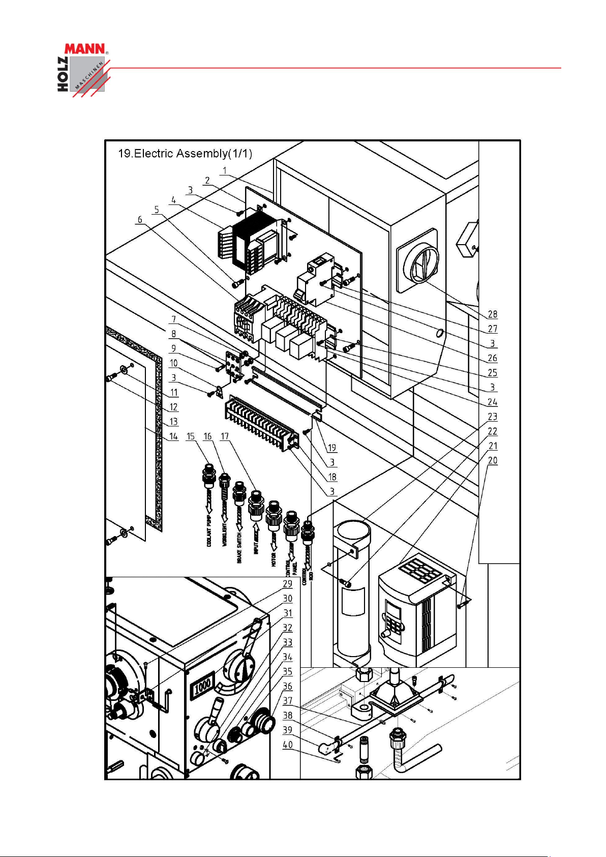
CHYBA! POMOCÍ KARTY DOMŮ POUŽIJTE U TEXTU, KTERÝ SE MÁ ZDE ZOBRAZIT, STYL
ÜBERSCHRIFT 1.
HOLZMANN Maschinen Austria www.holzmann-maschinen.at Seite 75
Metalldrehbank/Metal turning lathe ED1000F
Page 76
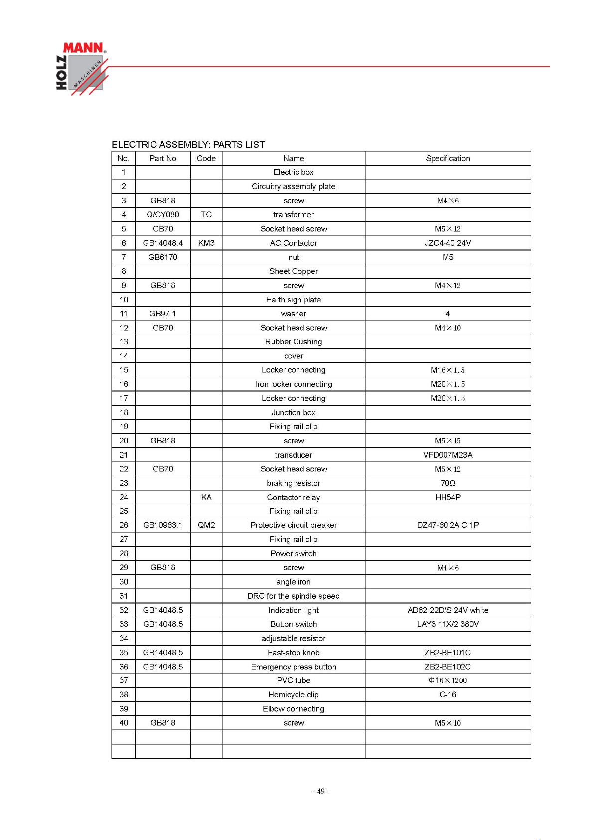
CHYBA! POMOCÍ KARTY DOMŮ POUŽIJTE U TEXTU, KTERÝ SE MÁ ZDE ZOBRAZIT, STYL
ÜBERSCHRIFT 1.
HOLZMANN Maschinen Austria www.holzmann-maschinen.at Seite 76
Metalldrehbank/Metal turning lathe ED1000F
Page 77
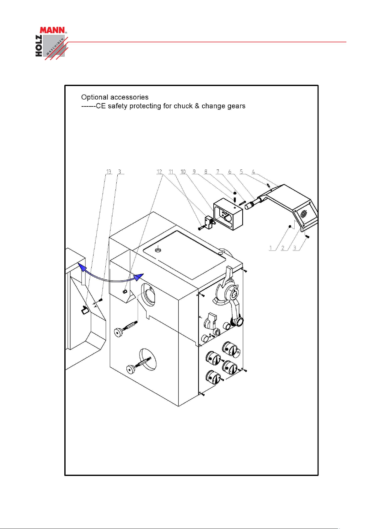
CHYBA! POMOCÍ KARTY DOMŮ POUŽIJTE U TEXTU, KTERÝ SE MÁ ZDE ZOBRAZIT, STYL
ÜBERSCHRIFT 1.
HOLZMANN Maschinen Austria www.holzmann-maschinen.at Seite 77
Metalldrehbank/Metal turning lathe ED1000F
Page 78
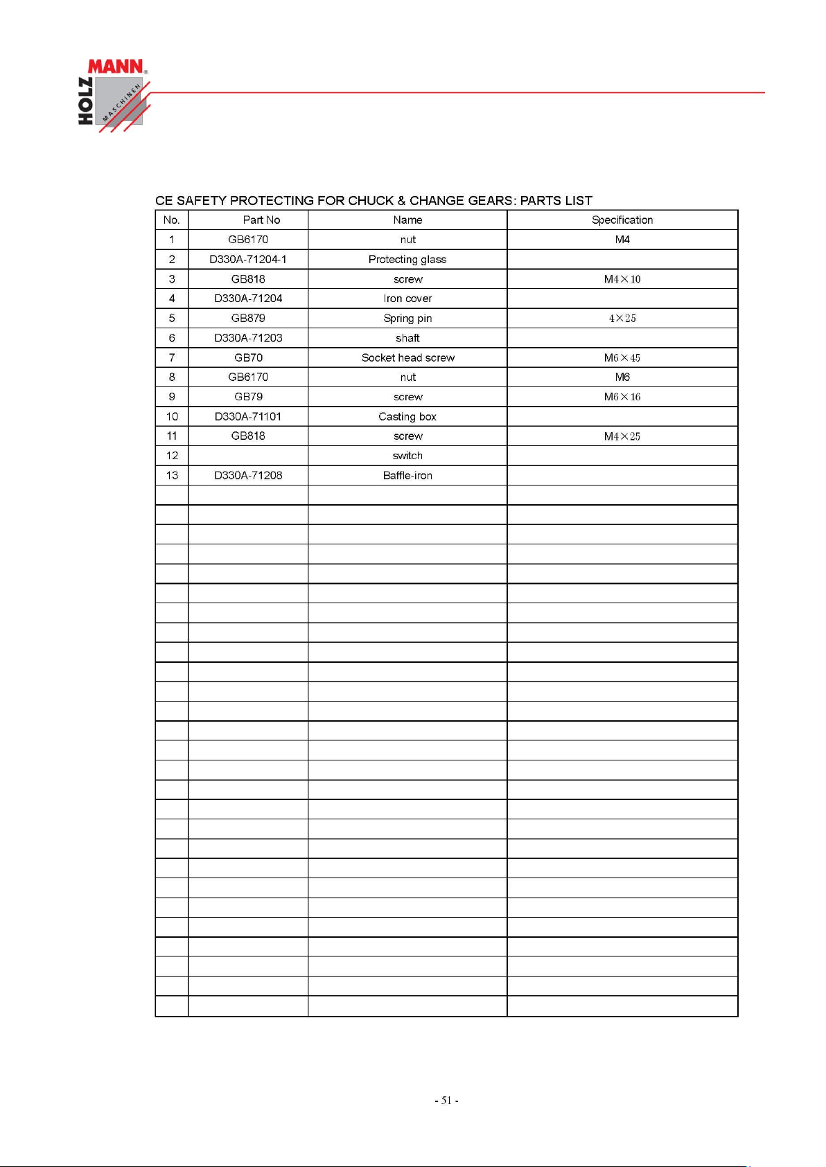
CHYBA! POMOCÍ KARTY DOMŮ POUŽIJTE U TEXTU, KTERÝ SE MÁ ZDE ZOBRAZIT, STYL
ÜBERSCHRIFT 1.
HOLZMANN Maschinen Austria www.holzmann-maschinen.at Seite 78
Metalldrehbank/Metal turning lathe ED1000F
Page 79
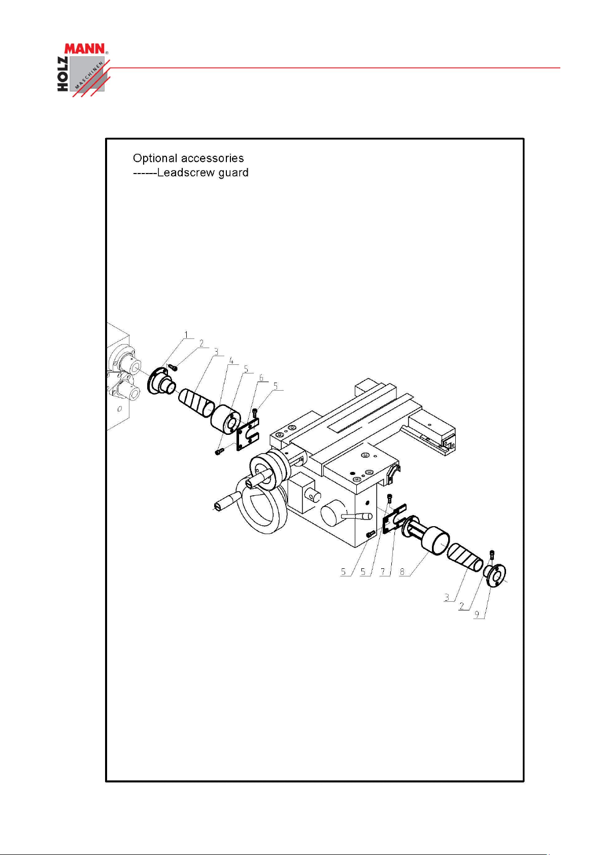
CHYBA! POMOCÍ KARTY DOMŮ POUŽIJTE U TEXTU, KTERÝ SE MÁ ZDE ZOBRAZIT, STYL
ÜBERSCHRIFT 1.
HOLZMANN Maschinen Austria www.holzmann-maschinen.at Seite 79
Metalldrehbank/Metal turning lathe ED1000F
Page 80
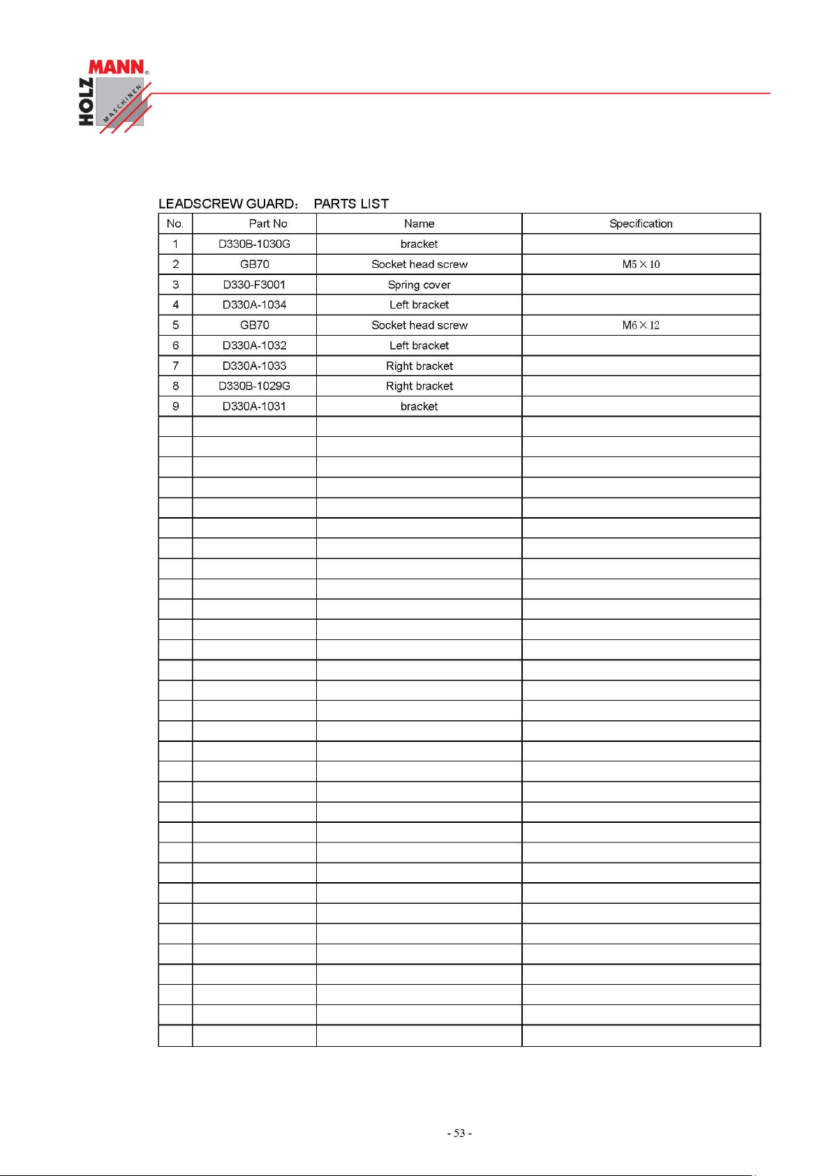
CHYBA! POMOCÍ KARTY DOMŮ POUŽIJTE U TEXTU, KTERÝ SE MÁ ZDE ZOBRAZIT, STYL
ÜBERSCHRIFT 1.
HOLZMANN Maschinen Austria www.holzmann-maschinen.at Seite 80
Metalldrehbank/Metal turning lathe ED1000F
Page 81
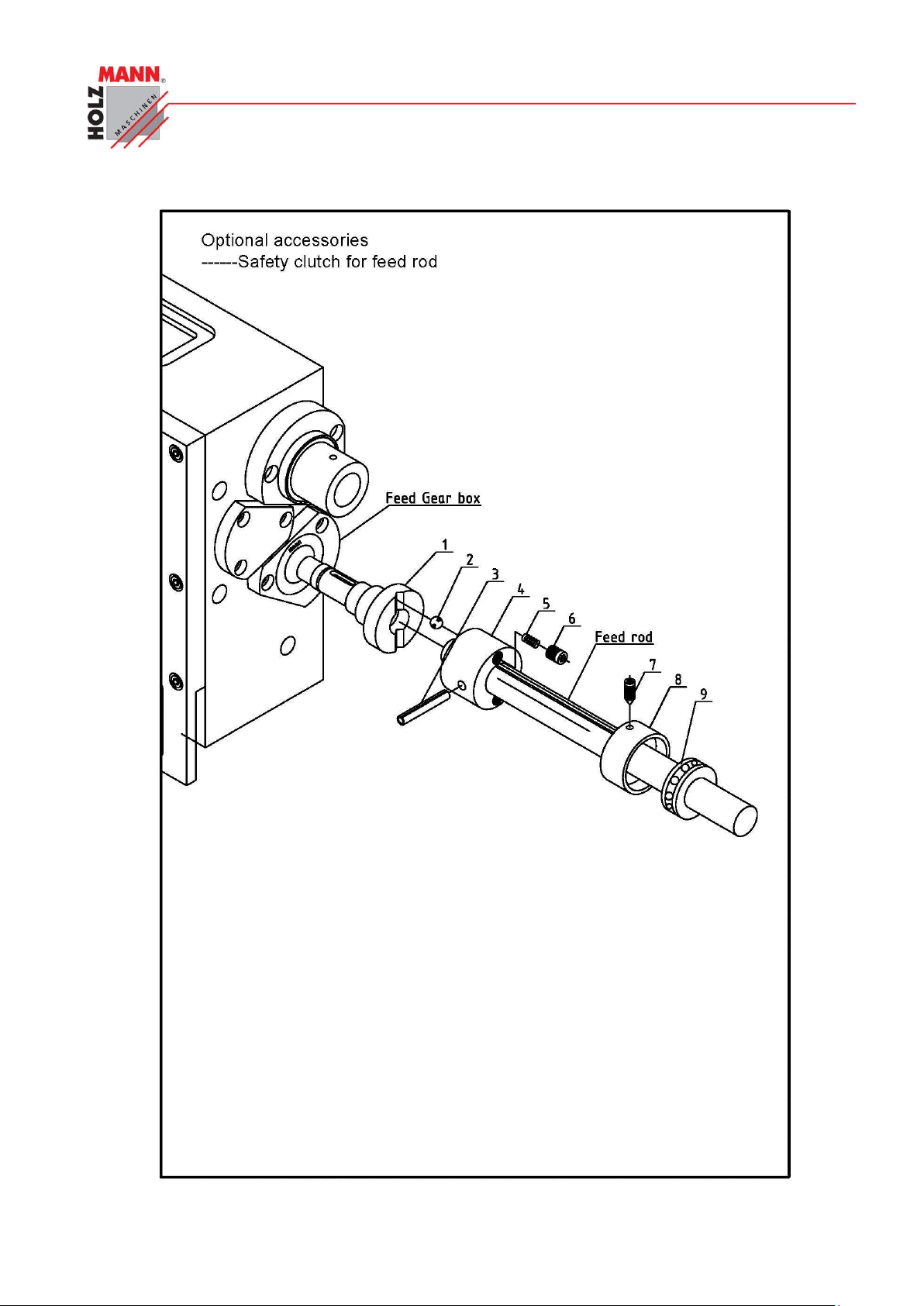
CHYBA! POMOCÍ KARTY DOMŮ POUŽIJTE U TEXTU, KTERÝ SE MÁ ZDE ZOBRAZIT, STYL
ÜBERSCHRIFT 1.
HOLZMANN Maschinen Austria www.holzmann-maschinen.at Seite 81
Metalldrehbank/Metal turning lathe ED1000F
Page 82
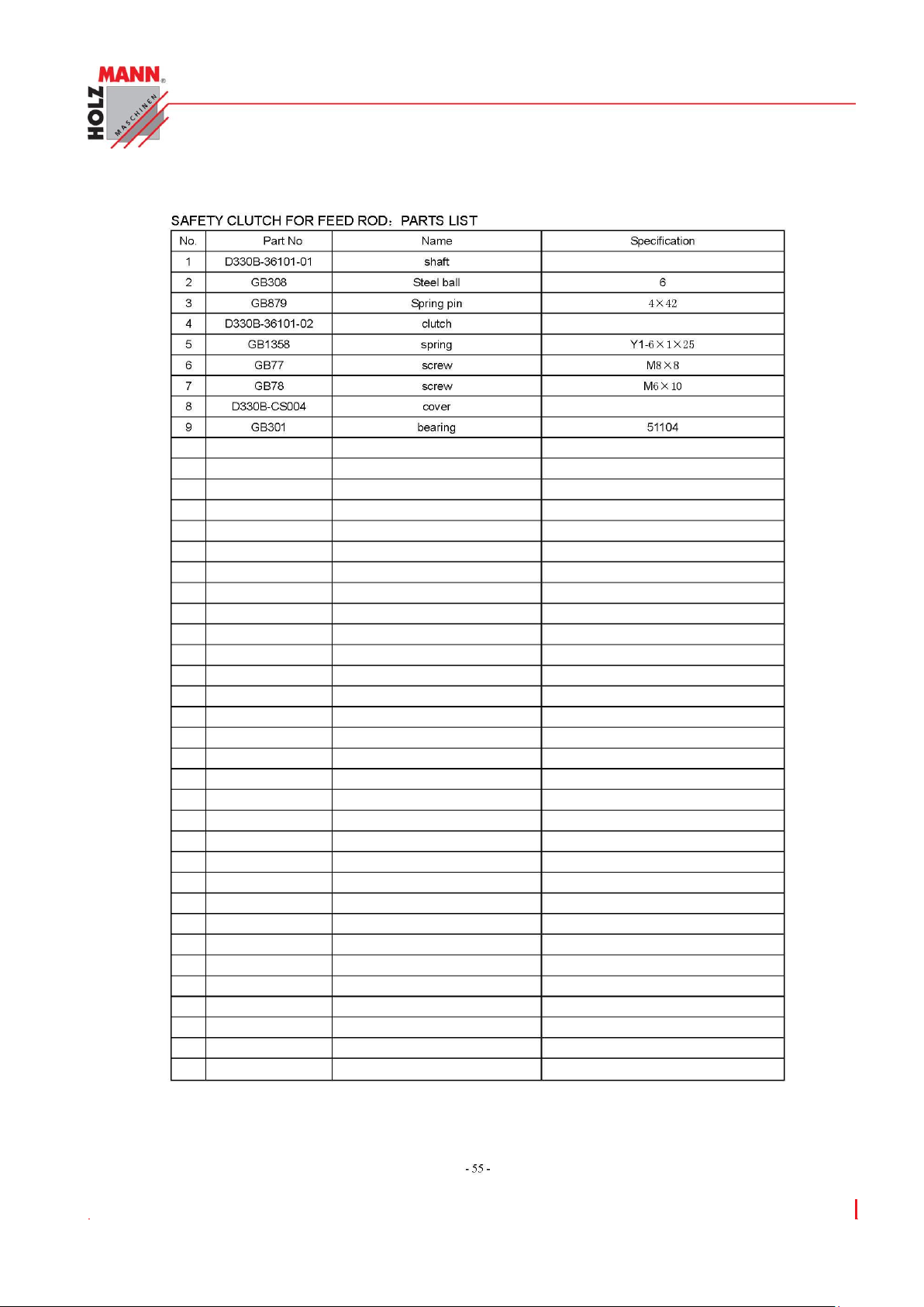
CHYBA! POMOCÍ KARTY DOMŮ POUŽIJTE U TEXTU, KTERÝ SE MÁ ZDE ZOBRAZIT, STYL
ÜBERSCHRIFT 1.
HOLZMANN Maschinen Austria www.holzmann-maschinen.at Seite 82
Metalldrehbank/Metal turning lathe ED1000F
Page 83
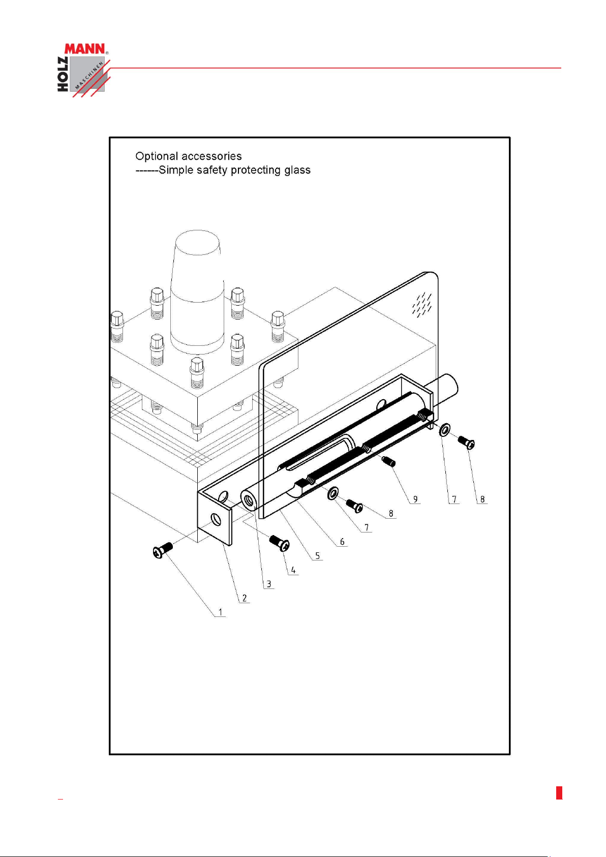
CHYBA! POMOCÍ KARTY DOMŮ POUŽIJTE U TEXTU, KTERÝ SE MÁ ZDE ZOBRAZIT, STYL
ÜBERSCHRIFT 1.
HOLZMANN Maschinen Austria www.holzmann-maschinen.at Seite 83
Metalldrehbank/Metal turning lathe ED1000F
Page 84
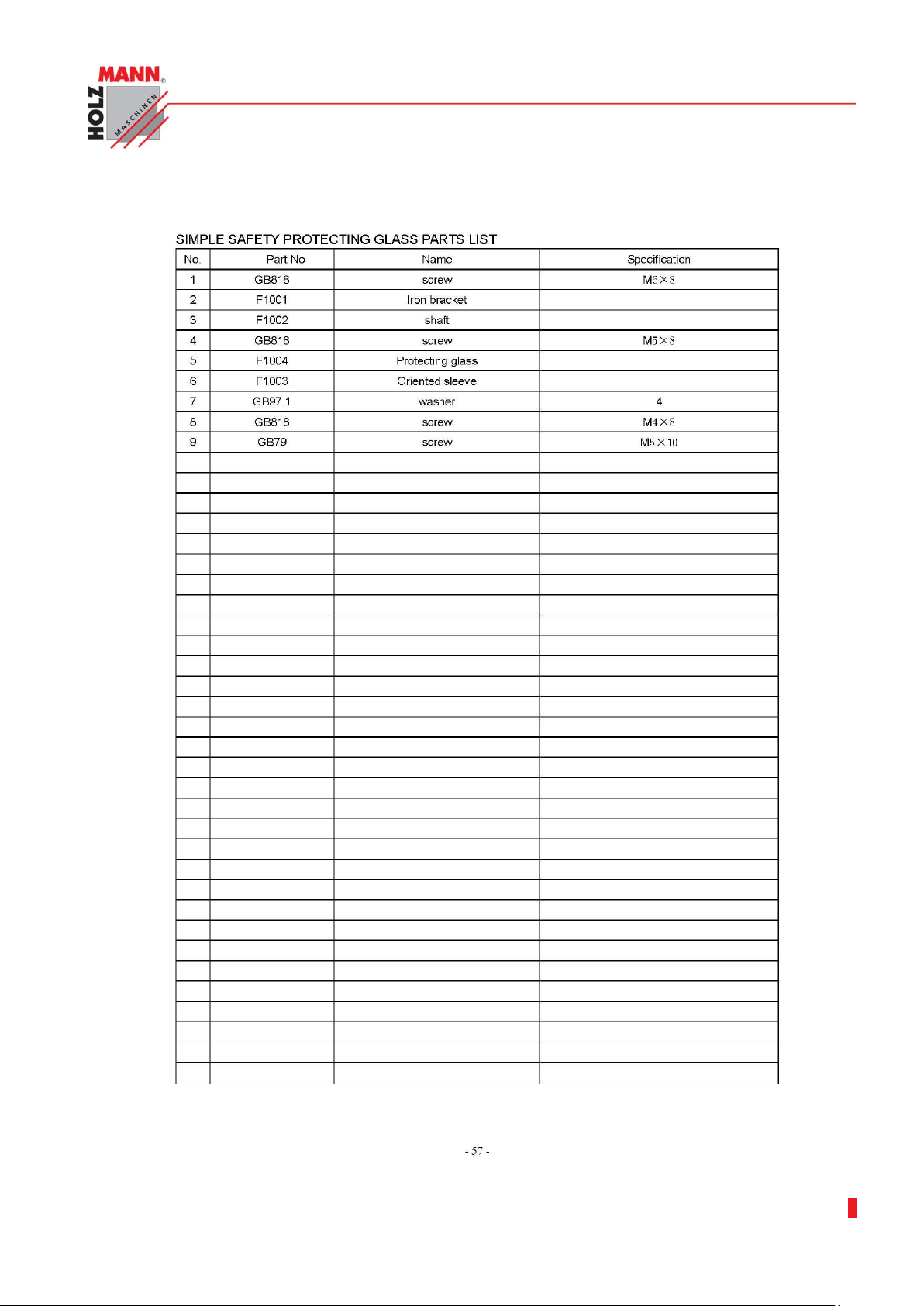
CHYBA! POMOCÍ KARTY DOMŮ POUŽIJTE U TEXTU, KTERÝ SE MÁ ZDE ZOBRAZIT, STYL
ÜBERSCHRIFT 1.
HOLZMANN Maschinen Austria www.holzmann-maschinen.at Seite 84
Metalldrehbank/Metal turning lathe ED1000F
Page 85
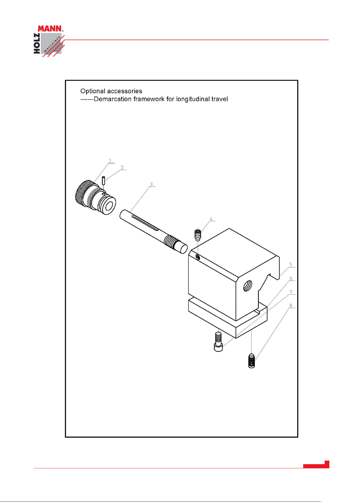
CHYBA! POMOCÍ KARTY DOMŮ POUŽIJTE U TEXTU, KTERÝ SE MÁ ZDE ZOBRAZIT, STYL
ÜBERSCHRIFT 1.
HOLZMANN Maschinen Austria www.holzmann-maschinen.at Seite 85
Metalldrehbank/Metal turning lathe ED1000F
Page 86
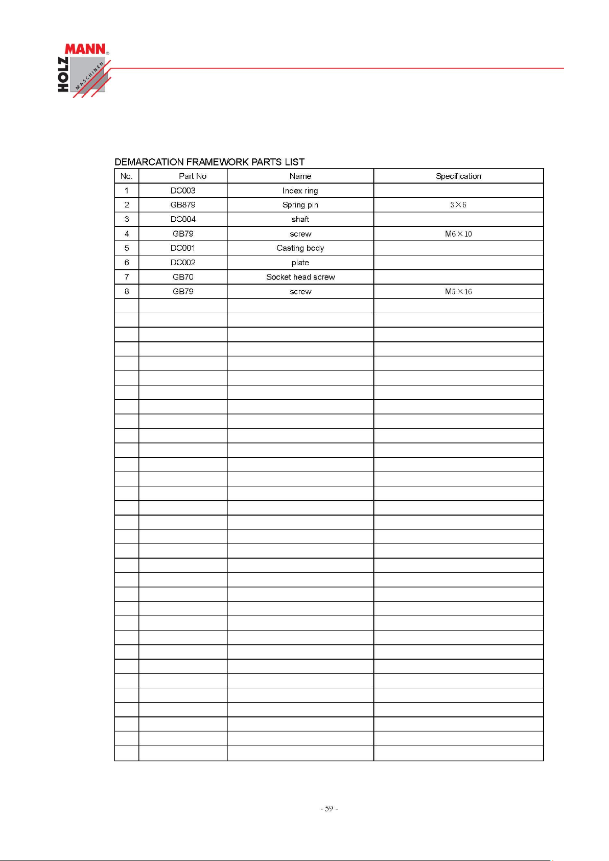
CHYBA! POMOCÍ KARTY DOMŮ POUŽIJTE U TEXTU, KTERÝ SE MÁ ZDE ZOBRAZIT, STYL
ÜBERSCHRIFT 1.
HOLZMANN Maschinen Austria www.holzmann-maschinen.at Seite 86
Metalldrehbank/Metal turning lathe ED1000F
Page 87
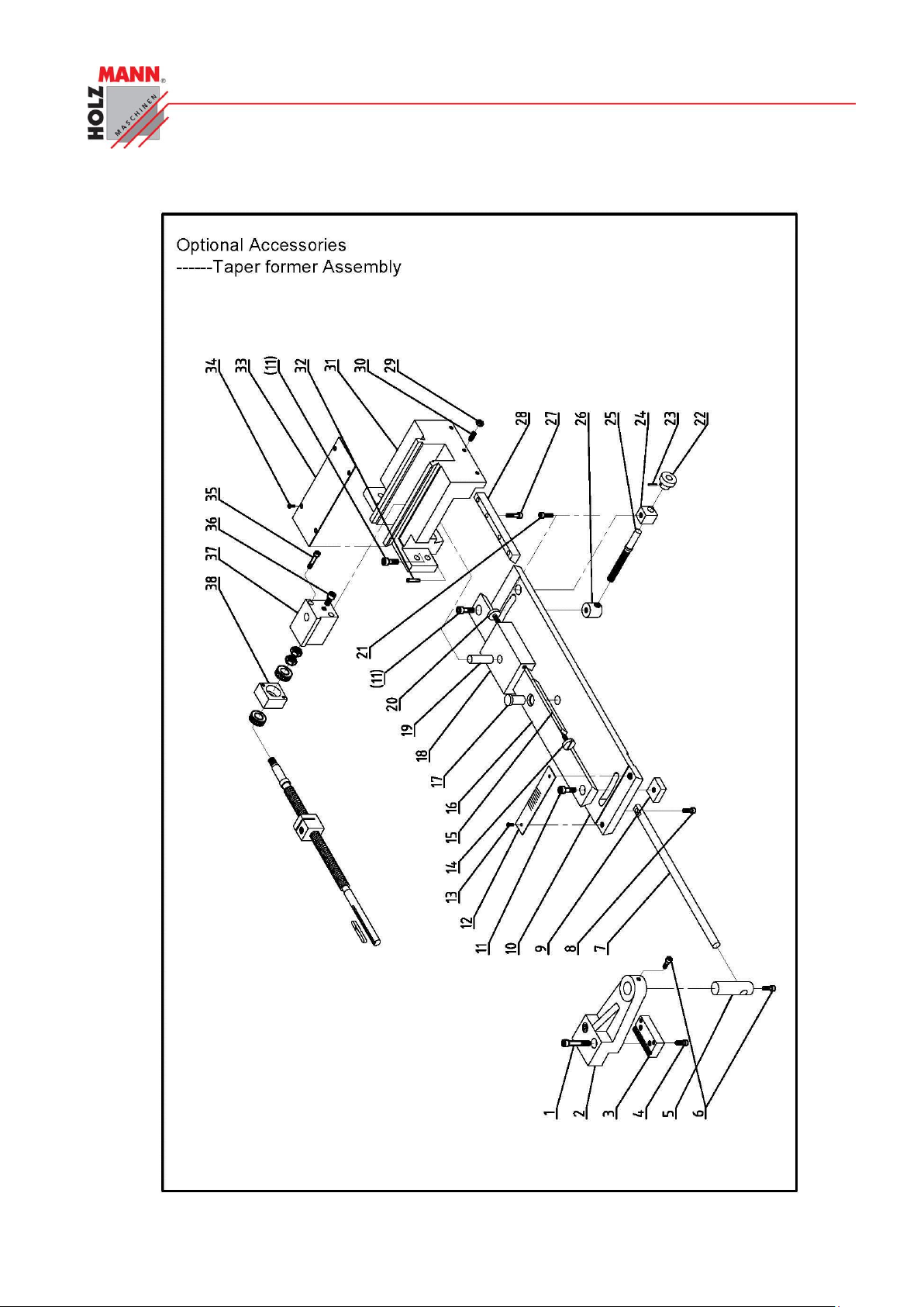
CHYBA! POMOCÍ KARTY DOMŮ POUŽIJTE U TEXTU, KTERÝ SE MÁ ZDE ZOBRAZIT, STYL
ÜBERSCHRIFT 1.
HOLZMANN Maschinen Austria www.holzmann-maschinen.at Seite 87
Metalldrehbank/Metal turning lathe ED1000F
Page 88
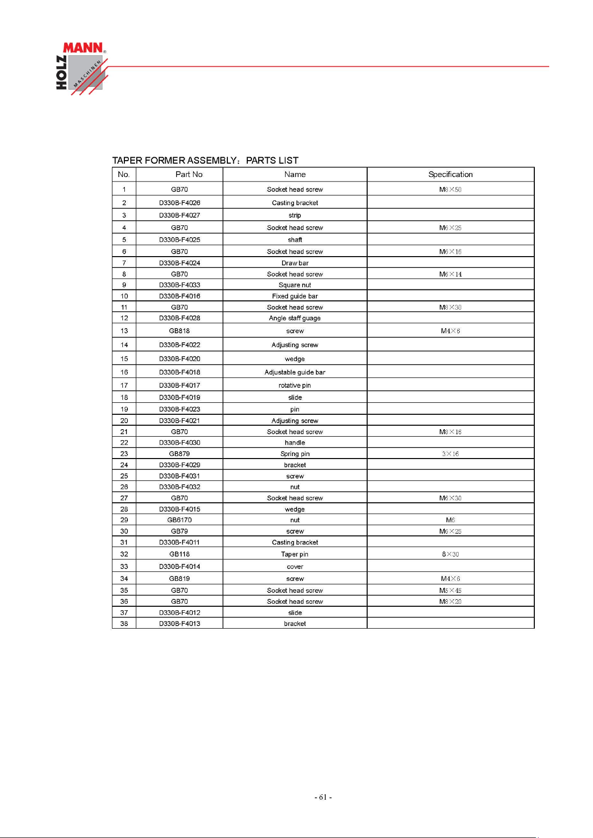
CHYBA! POMOCÍ KARTY DOMŮ POUŽIJTE U TEXTU, KTERÝ SE MÁ ZDE ZOBRAZIT, STYL
ÜBERSCHRIFT 1.
HOLZMANN Maschinen Austria www.holzmann-maschinen.at Seite 88
Metalldrehbank/Metal turning lathe ED1000F
Page 89
GARANTIEERKLÄRUNG
UP O ZO RN ĚN Í
Použití jiných než originálních náhradních dílů má za následek ztrátu záruky!
Platí:
Při výměně komponent/dílů používejte pouze originální náhradní díly.
IM P OR TA NT
The installation of non-original parts renders warranty null and void.
So you always have to use original spare parts.
1.39 Objednávky náhradních dílů
Použitím originálních dílů od společnosti Holzmann používáte díly, které spolu dokonale sedí
a jejich montáž je časově méně náročná. Originální náhradní díly zaručují delší životnost stro-
je.
Adresu pro objednání dílů naleznete v kontaktech na zákaznický servis v předmluvě této
dokumentace.
1.40 Spare part order
With original Holzmann spare parts you use parts that are attuned to each other and shorten
the installation time and elongate your machines lifespan.
You find the order address in the preface of this operation manual.
HOLZMANN Maschinen Austria www.holzmann-maschinen.at Seite 89
Metalldrehbank/Metal turning lathe ED1000F
Page 90

GARANTIEERKLÄRUNG
ZÁRUČNÍ PODMÍNKY
(Stav k 20.11.2011)
Záruční požadavky kupujícího vyplývající z kupní smlouvy a uplatněné u prodejce (obchodní zastoupení firmy Holzmann)
stejně jako práva vyplývající z legislativy příslušné země zůstávají tímto prohlášením nedotčeny.
Pro tento stroj platí následující záruční podmínky:
A)
Záruka zahrnuje bezplatné odstranění veškerých vad stroje, za předpokladu splnění podmínek dle bodů (B-G), které omezují správnou funkci stroje a jsou způsobeny vadou materiálu nebo výrobní vadou.
B)
Záruční doba je 12 měsíců, u komerčního použití 6 měsíců od dodání zboží prvnímu kupujícímu.
K reklamaci předložte originální doklad o dodání zboží a kupní doklad v případě vlastního odběru zboží.
C)
Pro nahlášení reklamace kontaktujte obchodní zastoupení společnosti HOLZMANN, u kterého jste výrobek pořídili a před-
ložte následující doklady:
a. Doklad o nákupu/nebo doklad o dodávce zboží
b. Vyplněný Servisní formulář s hlášením vady
c. Při požadavku na dodání náhradního dílu kopii výkresu náhradních dílů s vyznačením
D)
Průběh řešení reklamace a místo plnění určuje společnost HOLZMANN GmbH.
Snadno odstranitelné vady budou odstraněny obchodním zastoupením, u rozsáhlejších vad si vyhrazujeme právo
na odborné posouzení na adrese sidla firmy č. 4707 Haslach, Österreich. Pokud není v servisní smlouvě explicitně
uvedeno jinak, platí, že místem pro vyřízení reklamace je sídlo společnosti HOLZMANN-MASCHINEN na adrese 4707
Haslach, Österreich. Tato záruka výrobce nekryje případné náklady na přepravu zboží do sídla firmy.
E)
Výluky ze záruky:
F)
V rámci této záruky jsou další nároky kupujícího nad rámec plnění uvedeného v tomto dokumentu vyloučeny.
G)
Tyto záruční podmínky přijímá kupující ze svobodné vůle. Tato záruka vylučuje případné prodloužení záruční doby, a to i
na náhradní díly.
- Na díly, které vykazují známky opotřebení a při vadách stroje, které jsou následkem běžného opotřebení.
- Při nevhodné nebo nedbalé montáži stroje, chybného uvedení do provozu příp. nevhodného připojení k el-
ektrické síti.
- Při nedodržení pokynů pro obsluhu stroje, nevhodném použití, nestandardních podmínkách prostředí,
nevhodných podmínkách pro provoz, nedostatečné údržbě a péči o stroj atd.
- Při použití a/nebo zamontování neoriginálních dílů a příslušenství nebo při dodatečných úpravách, které nejsou
schváleny společností HOZMANN.
- U zanedbatelných odchylek výrobku od jeho popisu, přičemž tyto nemají vliv na hodnotu nebo použití stroje pro
dané účely.
- Při překročení zátěže stroje. Zejména při vadách způsobených přetížením stroje z důvodu jeho vytížení pro
komerční účely, pro které tento stroj nebyl zkonstruován.
SERVIS
Po uplynutí záruční doby mohou být opravy realizovány i u neautorizovaných servisních firem.
K dispozici je Vám samozřejmě i nadále servis společnosti HOLZMANN-Maschinen GmbH.
V takovém případě uplatněte Vaše nezávazné poptávky/reklamace s údaji dle bodu C) na náš zákaznický servis nebo nám
pošlete vyplněný přiložený servisní formulář.
Mail:
FAX: +43 (0) 7248 61116 6
potřebného dílu.
GUARANTEE TERMS
(applicable from 20.11.2011)
HOLZMANN Maschinen Austria www.holzmann-maschinen.at Seite 90
Metalldrehbank/Metal turning lathe ED1000F
Page 91

GARANTIEERKLÄRUNG
Please consult our troubleshooting section for initial problem solving. Feel free to contact your HOLZMANN
reseller or us for Customer Support!
Warranty claims based on your sales contract with your HOLZMANN retailer, including your statutory rights,
shall not be affected by this guarantee declaration. HOLZMANN-MASCHINEN grants guarantee according to
following conditions:
A) The guarantee covers the correction of deficiencies to the tool/machine, at no charge, if it can be
verified adequately that the deficiencies were caused by a material or manufacturing fault.
B) The guarantee period lasts 12 months, and is reduced to 6 months for tools in commercial use. The
guarantee period begins from the time the new tool is purchased from the first end user. The starting date is the date on the original delivery receipt, or the sales receipt in the case of pickup by the
customer.
C) Please lodge your guarantee claims to your HOLZMANN reseller you acquired the claimed tool from
with following information:
>> Original Sales receipt and/or delivery receipt
>> Service form (see next page) filed, with a sufficient deficiency report
>> for spare part claims: a copy of the respective exploded drawing with the required spare parts
being marked clear and unmistakable.
D) The Guarantee handling procedure and place of fulfillment is determined according to HOLZMANNs
sole discretion in accordance with the HOLZMANN retail partner. If there is no additional Service contract made including on-site service, the place of fulfillment is principally the HOLZMANN Service
Center in Haslach, Austria.
E) Transport charges for sendings to and from our Service Center are not covered in this guarantee.
The Guarantee does not cover:
- Wear and tear parts like belts, provided tools etc., except to initial damage which has to
be claimed immediately after receipt and initial check of the machine.
- Defects in the tool caused by non-compliance with the operating instructions, improper
assembly, insufficient power supply, improper use, abnormal environmental conditions,
inappropriate operating conditions, overload or insufficient servicing or maintenance.
- Damages being the causal effect of performed manipulations, changes, additions made to
the machine.
- Defects caused by using accessories, components or spare parts other than original
HOLZMANN spare parts.
- Slight deviations from the specified quality or slight appearance changes that do not af-
fect functionality or value of the tool.
- Defects resulting from a commercial use of tools that - based on their construction and
power output - are not designed and built to be used within the frame of industrial/commercial continuous load.
F) Claims other than the right to correction of faults in the tool named in these guarantee conditions
are not covered by our guarantee.
G) This guarantee is voluntary. Therefore Services provided under guarantee do not lengthen or renew
the guarantee period for the tool or the replaced part.
SERVICE
After Guarantee and warranty expiration specialist repair shops can perform maintenance and repair jobs.
But we are still at your service as well with spare parts and/or machine service. Place your spare part / repair service cost inquiry by filing the SERVICE form on the following page and send it:
HOLZMANN Maschinen Austria www.holzmann-maschinen.at Seite 91
Metalldrehbank/Metal turning lathe ED1000F
Page 92
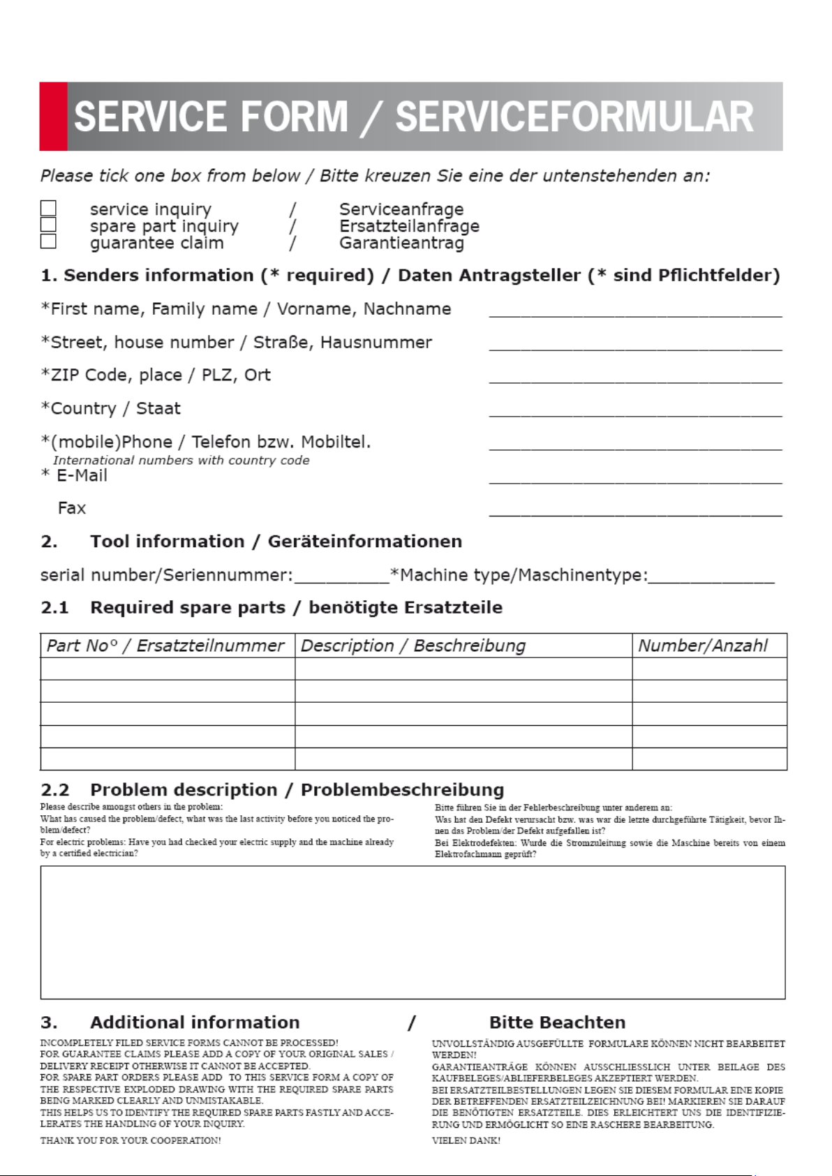
Page 93

Sledování výrobku
Product experience form
Po dodání nás zajímá Vaše spokojenost
s výrobkem.
We observe the quality of our delivered products
in the frame of a Quality Management policy.
Při procesu zlepšování výrobků jsme totiž závislí na Vás a Vašich zkušenostech s prací se
strojem.
Your opinion is essential for further product development and product choice. Please let us
know about your:
- Návrhy na zlepšení výrobku.
- Impressions and suggestions for improve-
ment.
- Problémy, které se vyskytly v určitých
provozních situacích.
- experiences that may be useful for other us-
ers and for product design
- Vaše zkušenosti, které mohou být důležité i
pro ostatní uživatele
- Experiences with malfunctions that occur in
specific operation modes
Prosíme Vás proto o zaznamenání Vašich
zkušeností a poznatků z provozu a jejich
zaslání na naši adresu:
We would like to ask you to note down your experiences and observations and send them to us
via FAX, E-Mail or by post:
J m é n o / N a m e :
V ý r o b e k / P r o d u c t :
D a t u m n á k u p u / P u r c h a s e d a t e :
P r o d e j c e / P u r c h a s e d f r o m :
M o j e E m a i l o v á a d r e s a / M y E m a i l :
D ě k u j e m e z a V a š i s p o l u p r á c i ! / T h a n k y o u f o r y o u r k i n d c o o p e r a t i o n !
KONTAKT / CONTACTS:
HOLZMANN MASCHINEN GmbH
4170 Haslach, Marktplatz 4 AUSTRIA
Fax 0043 7248 61116-6
Moje postřehy/ My experiences:
 Loading...