

Page 1
Přečtěte si tento návod na
obsluhu a dodržujte
bezpečnostní pokyny!
Technické změny a
tiskové chyby vyhrazeny!
Read the operation manual
carefully before first use!
Technical data subject to
changes, errors excepted!
CZ
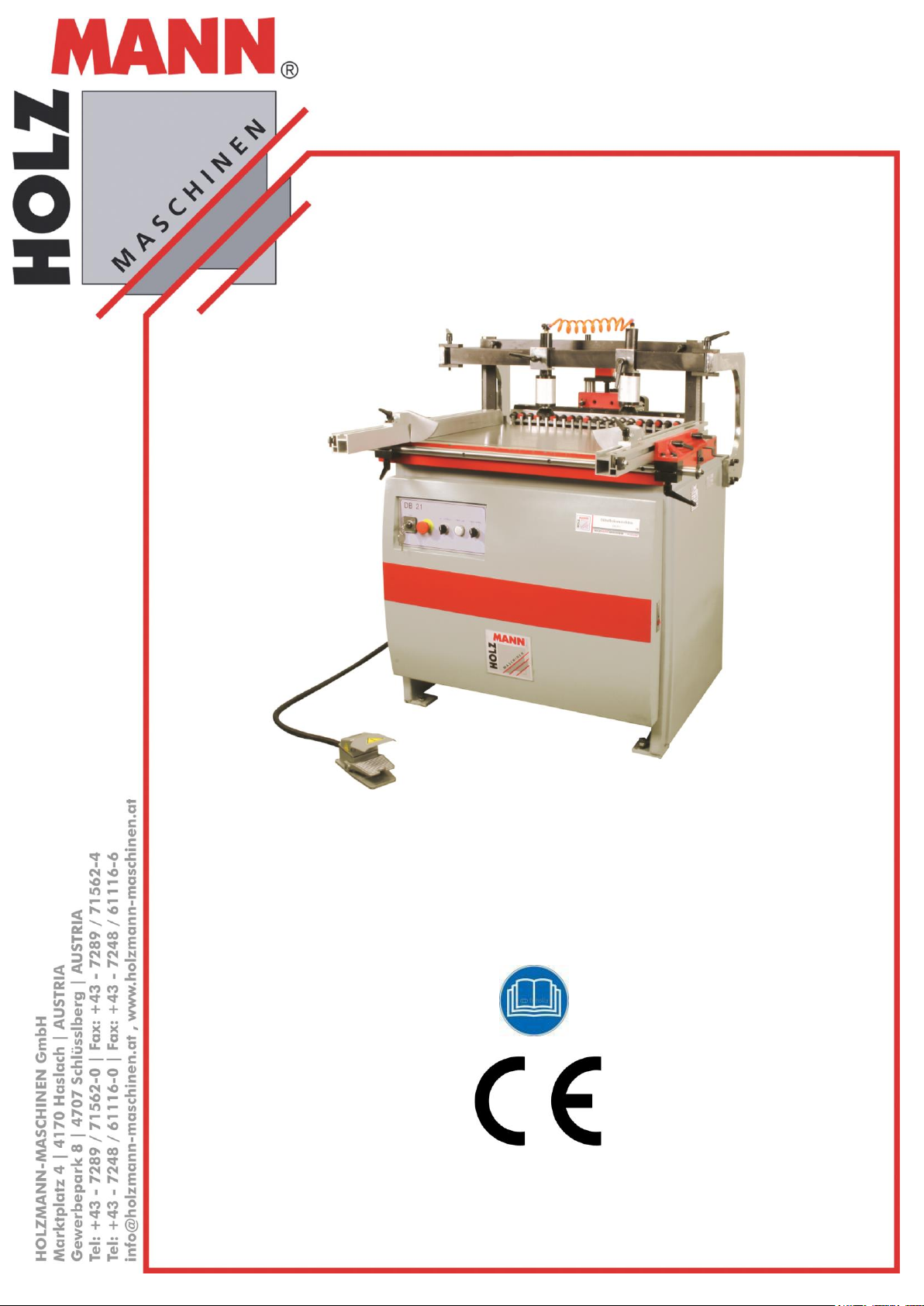
NÁVOD NA OBSLUHU
KOLÍKOVAČKA
EN
USER MANUAL
SINGLE-RAW MULTI-BORING MACHINE
DBM 21N
KOLÍKOVAČKA
SINGLE-RAW MULTI-BORING MACHINE
Vydání: 24.06.2014 – Revize 00 – GBR- CZ/EN
Page 2

1 OBSAH /INDEX
1 OBSAH /INDEX 2
2 PŘEDMLUVA 5
3 BEZPEČNOSTNÍ SYMBOLY / SAFETY SIGNS 6
4 TECHNIKA 7
4.1 Hlavní komponenty ............................................................................................. 7
4.2 Ovládací prvky ..................................................................................................... 7
4.3 Technické údaje .................................................................................................. 8
5 BEZPEČNOST 8
5.1 Účel použití ......................................................................................................... 8
5.2 Nedovolené použití .............................................................................................. 8
5.3 Všeobecné bezpečnostní pokyny ......................................................................... 9
5.4 Bezpečnostní výbava stroje DBM 21N ................................................................ 10
5.5 Další rizika ........................................................................................................ 10
6 MONTÁŽ 11
6.1 Součást dodávky ............................................................................................... 11
6.1.1 Pracoviště .................................................................................................... 11
6.1.2 Transport / Vykládka stroje ............................................................................ 11
6.1.3 Příprava plochy ............................................................................................. 11
6.2 Sestavení ........................................................................................................... 12
6.2.1 Elektrická přípojka ........................................................................................ 12
6.3 Nastavení před uvedením do provozu ................................................................ 13
6.3.1 Instalace / výměna vrtáků ............................................................................. 13
6.3.2 Montáž hadice tlakového vzduchu ................................................................... 14
6.3.3 Montáž redukčního ventilu ............................................................................. 14
6.3.4 Vrtací jednotka: Nastavení 90 stupňů .............................................................. 15
6.3.5 90 stupňový doraz ........................................................................................ 15
6.3.6 Horizontální doraz ......................................................................................... 15
6.3.7 45 stupňový doraz ........................................................................................ 16
6.3.8 Paralelita vrtací jednotky s plochou pracovního stolu ......................................... 16
7 PROVOZ 18
7.1 Obsluha ............................................................................................................. 18
7.1.1 Variabilní poloha přítlačného válce .................................................................. 18
HOLZMANN MASCHINEN GmbH www.holzmann-maschinen.at Strana 2
KOLÍKOVAČKA / SINGLE-RAW MULTI-BORING MACHINE DBM 21N
Page 3

7.1.2 Nastavení sklopného dorazu ........................................................................... 18
7.1.3 Nastavení digitálního ukazatele na nulu ........................................................... 19
7.1.4 Spuštění / Zastavení stroje ............................................................................ 20
8 ÚDRŽBA 21
8.1 Mazání ............................................................................................................... 22
8.2 Čištění ............................................................................................................... 22
8.3 Likvidace ........................................................................................................... 22
9 ODSTRAŇOVÁNÍ ZÁVAD 23
10 PREFACE 24
11 TECHNIC 25
11.1 Main components .......................................................................................... 25
11.2 Controls ........................................................................................................ 25
11.3 Technical Details ........................................................................................... 26
12 SAFETY 26
12.1 Intended use ................................................................................................. 26
12.2 Intended Use................................................................................................. 26
12.3 General Safety ............................................................................................... 27
12.4 Safety equipment of DBM 21N ....................................................................... 28
12.5 Residual risks ................................................................................................ 28
13 ASSEMBLY 28
13.1 Delivery content ............................................................................................ 28
13.2 The workplace ............................................................................................... 28
13.2.1 Transport ................................................................................................ 28
13.2.2 Preperation of the surface ......................................................................... 29
13.3 Assembly ....................................................................................................... 29
13.4 Power supply ................................................................................................ 30
13.5 Adjustments before operation ....................................................................... 31
13.5.1 Installing / Replacing Boring Bits ................................................................ 31
13.5.2 Setting the folding stopper ........................................................................ 32
13.5.3 Attaching Air Hose ................................................................................... 32
13.5.4 Air Supply Connection .............................................................................. 32
13.5.5 Boring Head: 90 Degree Pivot .................................................................... 33
13.5.6 90 Degree Stop ....................................................................................... 34
13.5.7 Horizontal Stop ........................................................................................ 34
HOLZMANN MASCHINEN GmbH www.holzmann-maschinen.at Strana 3
KOLÍKOVAČKA / SINGLE-RAW MULTI-BORING MACHINE DBM 21N
Page 4

13.5.8 45 Degree Stop ....................................................................................... 34
13.5.9 Clamp Position and Pressure ...................................................................... 35
13.5.10 Parallelism of Boring Head to Table Surface ................................................. 35
13.5.11 “Zero” the Digital Readout ........................................................................ 36
14 OPERATION 37
14.1.1 Limit Switch ............................................................................................ 38
14.2 Operation ...................................................................................................... 38
15 MAINTENANCE 39
15.1 Lubrication .................................................................................................... 40
15.2 Cleaning ........................................................................................................ 40
15.3 Disposal ........................................................................................................ 40
16 TROUBLE SHOOTING 41
17 PLÁNY ZAPOJENÍ / DIAGRAMS 42
17.1 ELEKTRICKÉ ZAPOJENÍ / WIRING DIAGRAM................................................. 42
17.2 Schéma pneumatického zapojení / Pneumatic diagram ................................ 43
18 NÁHRADNÍ DÍLY / SPARE PARTS 44
18.1 Obejdnávky náhradních dílů / spare parts order ........................................... 44
19 PROHLÁŠENÍ O SHODĚ / CERTIFICATE OF CONFORMITY 53
20 ZÁRUČNÍ PODMÍNKY 54
21 GUARANTEE TERMS 55
22 SLEDOVÁNÍ VÝROBKU 56
PRODUCT EXPERIENCE FORM 56
HOLZMANN MASCHINEN GmbH www.holzmann-maschinen.at Strana 4
KOLÍKOVAČKA / SINGLE-RAW MULTI-BORING MACHINE DBM 21N
Page 5
2 PŘEDMLUVA
HOLZMANN MASCHINEN
A-4170 Haslach, Marktplatz 4
Tel +43 7289 71562 - 0
Fax +43 7289 71562 – 4
Vážený zákazníku!
Tento návod na obsluhu obsahuje důležité informace a upozornění k manipulaci a provozu multi-
kolíkovačky DBM 21N.
Obchodní označení výrobku bude pro účel tohoto návodu zkráceno na „stroj“.
Tento návod na obsluhu je nedílnou součástí stroje a musí být u něj uchován pro
případné pozdější použití. Pokud stroj předáváte třetí osobě, vždy návod přiložte!
Dodržujte bezpečnostní pokyny!
Před prvním použitím si pozorně přečtěte tento návod na obsluhu. To Vám usnadní práci se
strojem a pomůže předcházet chybám a případným škodám.
Dodržujte bezpečnostní pokyny a dbejte výstrah. Opomíjení bezpečnostních pokynů může vést
k vážným škodám na zdraví apod.
Z důvodu neustálého vývoje našich produktů se mohou vyobrazení nebo obsah tohoto návodu
mírně lišit od skutečnosti. V případě zjištění nedostatků této dokumentace nás o těchto laskavě
informujte.
Technické změny vyhrazeny!
Po dodání zkontrolujte bezodkladně stav zboží a v případě neshod a poškození
zaznamenejte tyto okamžitě do přepravního listu! Škody způsobené přepravou musí být
nahlášeny přímo u nás nejpozději do 24 hodin od dodání. Na pozdější reklamace
nebude brát společnost Holzmann zřetel.
Autorské právo
© 2014
Tato dokumentace je chráněna autorským právem. Z toho vyplývající ústavní práva zůstávají
nedotčena! Přetisk dokumentace, překlad, použití fotografií a vyobrazení budou trestně stíhána –
Místem soudu je Linz nebo příslušný soud pro 4170 Haslach.
Kontakt na služby zákazníkům
HOLZMANN MASCHINEN GmbH www.holzmann-maschinen.at Strana 5
KOLÍKOVAČKA / SINGLE-RAW MULTI-BORING MACHINE DBM 21N
Page 6
3 BEZPEČNOSTNÍ SYMBOLY / SAFETY SIGNS
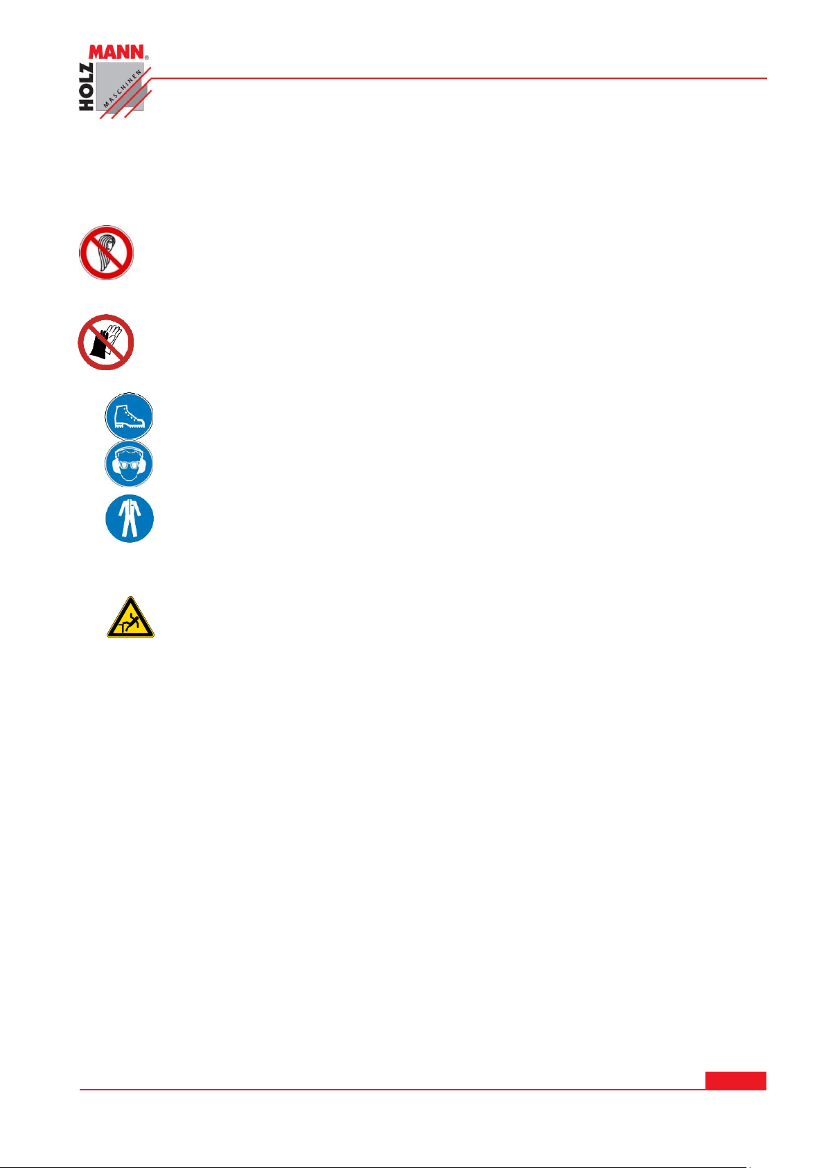
Používejte vhodné ochranné prostředky (bezpečnostní obuv s Stahlkappen,
pracovní rukavice, ochranné brýle, ochrana sluchu)!
Používejte vhodné pracovní oblečení, žádný volný příliš dlouhý oděv,
rozpuštěné vlasy, šperky apod. Může dojít k jejich namotání do stroje nebo
zachycení na jeho pohyblivé části!
Use proper safety clothing and devices when operating the machine (safety gloves,
safety goggles, ear protectors, safety shoes …)!
Na práci se soustřeďte, dbejte bezpečnostních pokynů a udržujte stabilní
postoj!
Always be focused when working, takecare to maintain a safe posture at every
time.
CZ
Zákaz obsluhy stroje s rozpuštěnými vlasy!
EN
Operation with long hair forbidden!
CZ
Zákaz používání rukavic!
EN
Prohibited use of gloves!
HOLZMANN MASCHINEN GmbH www.holzmann-maschinen.at Strana 6
KOLÍKOVAČKA / SINGLE-RAW MULTI-BORING MACHINE DBM 21N
Page 7
4 TECHNIKA
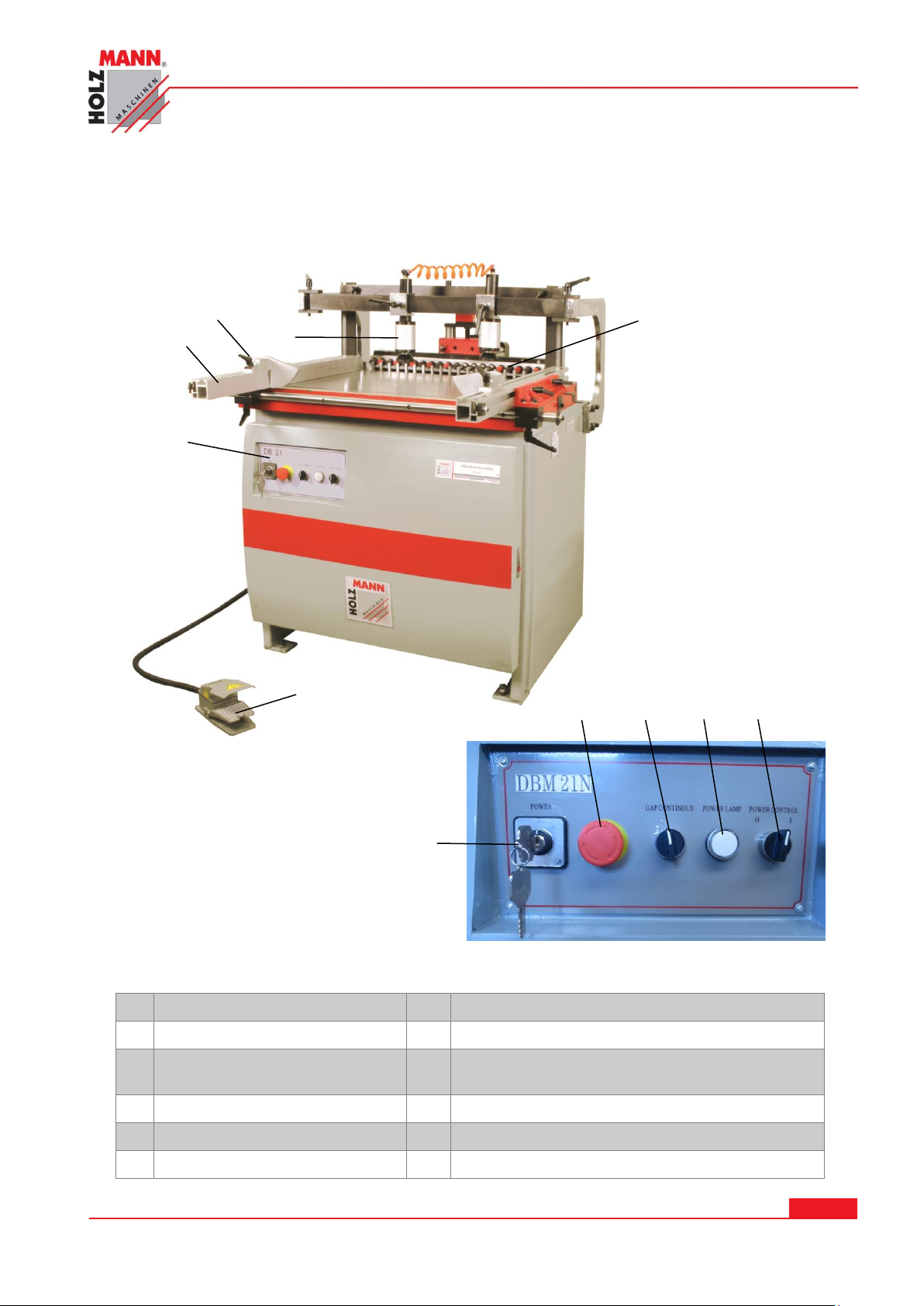
1
Ovládání
7
Hlavní vypínač
2
Lišta pravítka
8
Tlačítko NOUZOVÉHO ZASTAVENÍ
3
Sklopný doraz
9
Přepínač vertikální /horizontální vrtací
jednotky
4
Pneumatický přítlačný válec
10
Kontrolka provozu
5
Vrtací jednotka
11
ZAPNUTÍ/VYPNUTÍ motoru vřetene
6
Nožní pedál
4
2 5 1
6 3 8
7 9 10
11
4.1 Hlavní komponenty
4.2 Ovládací prvky
HOLZMANN MASCHINEN GmbH www.holzmann-maschinen.at Strana 7
KOLÍKOVAČKA / SINGLE-RAW MULTI-BORING MACHINE DBM 21N
Page 8
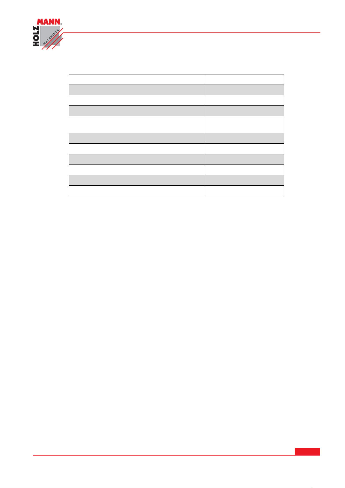
4.3 Technické údaje
Napětí
400V
Výkon motoru (S1 100%) (S6)
1,5 / 2,1 kW
Počet vřeten
21
Rozteč vrtacích vřeten
32mm
Vzdálenost mezi prvním a posledním
vřetenem
640mm
Max. hloubka vrtání
50mm
Otáčky vrtacího vřetene
2840 min-1
Rozměr stolu
870x550mm
Přípojka tlakového vzduchu
6 – 8 bar
Rozměry d x š x v
1100x1000x1000mm
Hmotnost
342kg
Vlhkost
max. 90%
Teplota
od +1°С
do +40°С
Nadmořská výška
max. 2000 m
5 BEZPEČNOST
5.1 Účel použití
Stroj používejte pouze v bezvadném technickém stavu, pouze pro povolené účely a osobami
poučenými o bezpečnosti práce se strojem! Závady, které by mohly narušit bezpečnost provozu
stroje, nechte okamžitě odstranit!
Obecně je zakázáno měnit nebo jakkoliv upravovat bezpečnostní prvky stroje!
Obsluhující osoba musí stroj ovládat zepředu.
Kolíkovačka DBM 21N slouží výhradně k vrtání kolíků v dřevěných obrobcích.
Stroj je určen pro provoz za následujících podmínek:
Stroj není určen pro venkovní provoz.
Stroj není určen pro provoz s rizikem exploze.
5.2 Nedovolené použití
Provoz stroje za podmínek přesahujících rámec použití uvedený v tomto návodu není dovolen.
Provoz stroje bez ochranných prostředků není dovolen.
Není dovolena demontáž nebo deaktivace ochranných prvků.
Není dovolen provoz stroje s obrobky, které nejsou výslovně uvedeny v tomto
návodu na obsluhu.
Není dovolené opracování obrobků o rozměrech překračujících limit uvedený v tomto návodu.
HOLZMANN MASCHINEN GmbH www.holzmann-maschinen.at Strana 8
KOLÍKOVAČKA / SINGLE-RAW MULTI-BORING MACHINE DBM 21N
Page 9
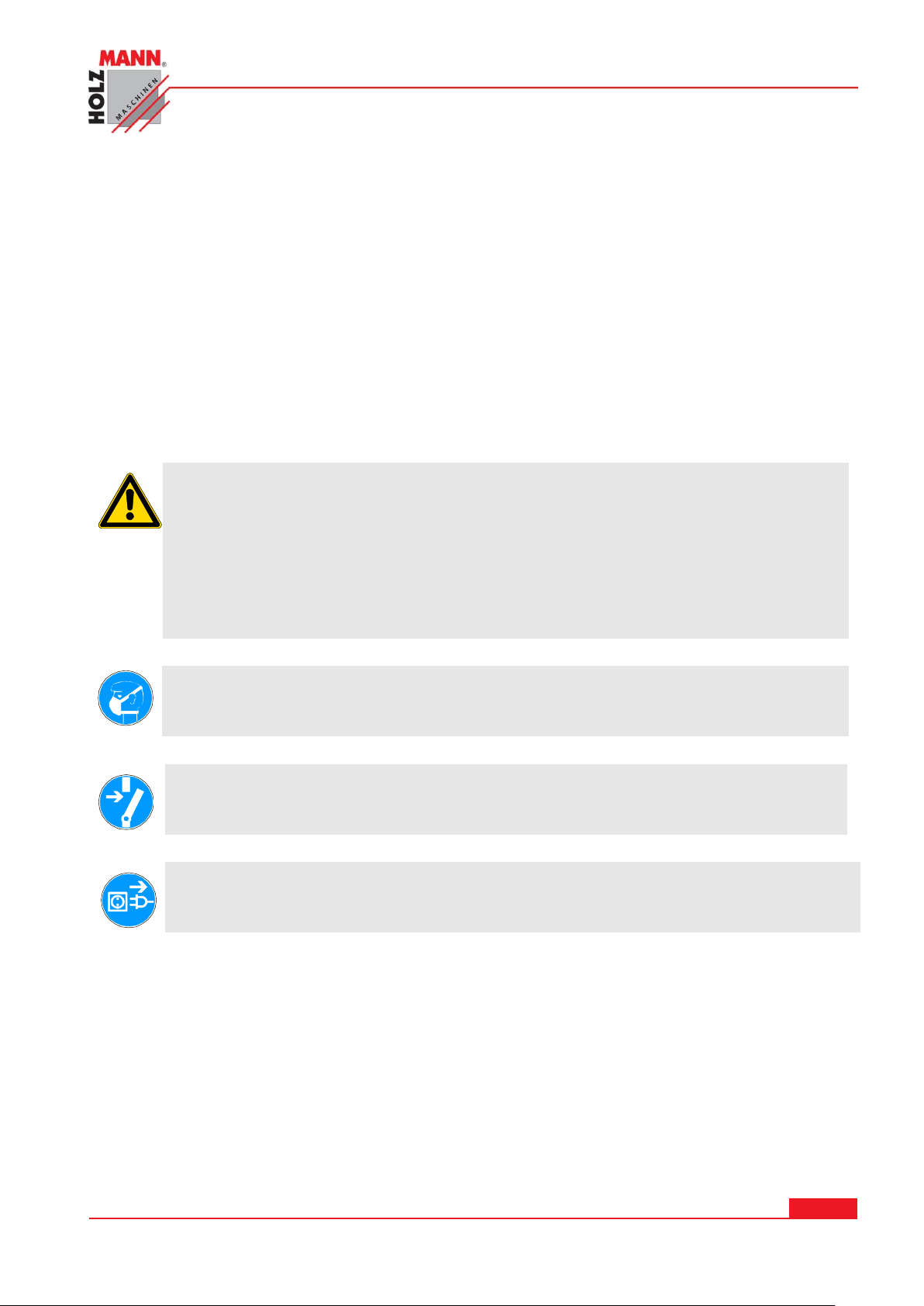
Není dovoleno použití nástrojů, které neodpovídají normám EN pro bezpečnost práce, a které
Pracovní prostor a podlahu kolem stroje udržujte čistou od oleje, mazacích tuků a
zbytků materiálu z opracování obrobků!
Zajistěte dostatečné osvětlení pracoviště, kde se stroj nachází!
Stroj NIKDY nepoužívejte venku!
Při únavě, špatné koncentraci, popř. pod vlivem léků, alkoholu nebo drog je práce
se strojem zakázaná!
Dřevěný prach může obsahovat chemické látky, které mohou mít negativní vliv na
zdraví osob. Stroj provozujte pouze v řádně větraných prostorech a za použití
vhodné ochranné masky!
Spuštěný stroj nesmí být nikdy ponechán bez dozoru!
Před opuštěním pracoviště stroj vypnětě a vyčkejte, dokud se hoblovací válec zcela
nezastaví!
Před výkonem údržby nebo při seřizování odpojte stroj ze sítě! Před odpojením ze site
vypněte stroj hlavním vypínačem (OFF)!
Pro transport nebo manipulaci se strojem nikdy nepoužívejte síťový kabel!
nejsou určeny pro průměr vrtáku.
Případné změny na konstrukci stroje nejsou dovolené.
Za škody a zranění způsobená jiným než ke svému účelu určenému použití stroje
nenese společnost HOLZMANN-MASCHINEN jakoukoliv odpovědnost nebo záruku.
5.3 Všeobecné bezpečnostní pokyny
Výstražné štítky a/nebo nálepky na stroji, které jsou již nečitelné nebo chybějí, musejí
být okamžitě obnoveny!
Pro zabránění vadné funkce stroje, jeho poškození nebo škodám na zdraví dbejte
VŽDY následujících pokynů:
Na stroji je pouze několik málo komponent, které vyžadují údržbu. Není nutné na stroji
cokoliv demontovat.
Opravy svěřte výhradně kvalifikovanému opraváři!
Příslušenství:
Používejte pouze příslušenství doporučené společností HOLZMANN!
V případě dotazů nebo potíží se obracejte na náš zákaznický servis.
HOLZMANN MASCHINEN GmbH www.holzmann-maschinen.at Strana 9
KOLÍKOVAČKA / SINGLE-RAW MULTI-BORING MACHINE DBM 21N
Page 10
UPOZORNĚNÍ
Postup v případě nouze
Pro případ nehody musí být vždy připravena lékárnička odpovídající normě DIN
13164. V případě úrazu poskytněte první pomoc. Po první pomoci zajistěte zápis
o něhodě následovně:
1. Místo nehody
2. Způsob nehody
3. Počet zraněných
4. Druh zranění
5.4 Bezpečnostní výbava stroje DBM 21N
Konstrukce stroje disponuje následující bezpečnostní výbavou:
NOUZOVÝ vypínač. Jeho správnou funkci kontrolujte v pravidelných intervalech.
5.5 Další rizika
I přes dodržování bezpečnostních předpisů a pokynů pro správné použití stroje hrozí další rizika:
Nebezpečí poranění rukou/prstů od rotujících částí stroje při jeho provozu.
Nebezpečí zranění od kontaktu s částmi stroje, které vedou elektrický proud.
Nebezpečí poranění od zlomeného nebo vymrštěného vrtáku, především v případě značného
přetížení stroje.
Poškození sluchu, pokud obsluha nezajistila preventivní opatření pro ochranu sluchu.
Tato rizika je možné minimalizovat při dodržování všech bezpečnostních pokynů, pokynů
k údržbě a péči o stroj a při vhodném používání stroje zaškolenou obsluhou.
HOLZMANN MASCHINEN GmbH www.holzmann-maschinen.at Strana 10
KOLÍKOVAČKA / SINGLE-RAW MULTI-BORING MACHINE DBM 21N
Page 11
6 MONTÁŽ
VÝSTRAHA
Zvednutí a transport stroje lze provádět pouze vyškoleným
personálem a s použitím patřičného vybavení.
UPOZORNĚNÍ
Použití ředidel na barvy, benzinu, agresivních chemikálií nebo jiných
odstraňovačů vede k trvalému poškození ošetřených ploch!
Platí: Pro čištění používejte pouze jemné čistící prostředky.
6.1 Součást dodávky
Po obdržení zásilky zkontrolujte, zda-li jsou všechny její části v pořádku. Poškození nebo chybějící
části okamžitě oznamte svému prodejci nebo přepravci. Viditelná poškození způsobená přepravou
musejí být neprodleně zaznamenána do dodacího listu. Na pozdější reklamace nebude brán
zřetel. Zboží bude považováno za řádně dodané.
Obsah:
Kolíkovcí jednotka, 400V přípojka, 4x sklopný doraz, ruční klika pro nastavení hloubky vrtání, 2x
podélné pravítko, 6-hranný klíč, 3x imbus klíč,
6x rychloupínací sklíčidlo pro vrták
6.1.1 Pracoviště
Pro stroj zvolte vhodné místo;
Dbejte přitom bezpečnostních pokynů podle kapitoly 5 a rozměrů stroje podle kapitoly 4.2
Zvolené místo musí disponovat příslušnou přípojkou na elektrickou síť a zároveň možností pro
připojení odsávacího zařízení.
Ujistěte se, že je nosnost podlahy dostatečná pro instalaci stroje. Stroj musí být vyrovnán
najednou na všechny své opěrné body.
Rovněž je nutné dodržet pracovní prostor kolem stroje minimálně 0.8 m.
6.1.2 Transport / Vykládka stroje
Vyzvednutí z obalu pro montáž a umístění na pracovišti:
Pouze pomocí vhodného zvedacího zařízení!
Dbejte na to, aby se použité zvedací zařízení (jeřáb, vysokozdvižný vozík, zvedací pás atd.)
nacházelo v bezvadném stavu.
K manipulaci stroje v balení lze použít také paletovací vozík popř. vysokozdvižný vozík.
6.1.3 Příprava plochy
Stroj zbavte konzervačního prostředku, kterým jsou opatřeny jeho části bez povrchové úpravy
(nátěru, laku apod.) z důvodu jeho ochrany proti korozi. Dekonzervaci lze provést běžnými
rozpouštědly. Nikdy nepoužívejte nitroředidla nebo obdobná rozpouštědla a v žádném případě
nepoužívejte vodu.
HOLZMANN MASCHINEN GmbH www.holzmann-maschinen.at Strana 11
KOLÍKOVAČKA / SINGLE-RAW MULTI-BORING MACHINE DBM 21N
Page 12
6.2 Sestavení
POZOR
Při práci na neuzemněném stroji:
Těžká poranění od rány elektrickým proudem, možnost vadné funkce stroje!
Platí:
Stroj musí být uzemněn a připojen k uzemněné zásuvce.
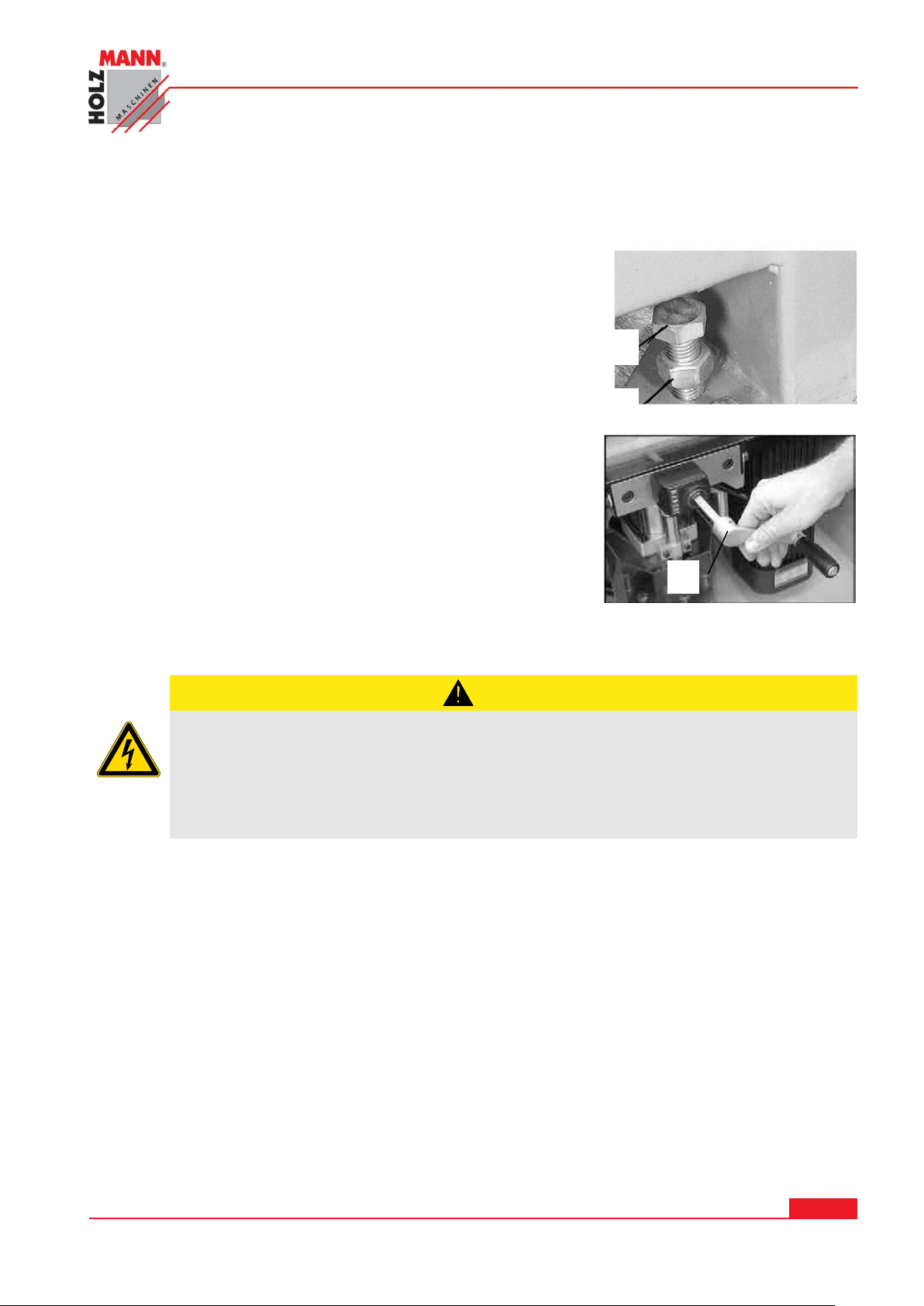
A
B
C
Stroj je dodán v předmontovaném stavu. Je nutné namontovat pouze elektrickou přípojku a
pravítka.
Stroj ustavte na pevnou podložku a vyrovnejte.
Povolte matku B, aby bylo možné vyšroubovat šroub A na
požadovanou výšku.
Až bude stroj vyrovnán na všechny 4 podpěry, utáhněte matku
B na všech 4 patkách.
Ruční kliku C pro nastavení hloubky vrtání nasaďte na
nastavovací vřeteno.
6.2.1 Elektrická přípojka
Připojení kolíkovačky DBM 21N na elektrickou síť a následná kontrola zapojení smí být
provedena pouze osobou s příslušným vzděláním resp. zkouškami.
Elektrické připojení stroje je připraveno pro provoz s uzemněnou zásuvkou!
Zástrčka může být zapojena pouze do uzemněné zásuvky, která byla nainstalována
elektrikářem!
Zástrčka dodaná se strojem nesmí být měněna.
Pokud je vadná nebo nevhodná, může být upravena nebo vyměněna pouze kvalifikovaným
elektrikářem!
Poškozený kabel musí být okamžitě vyměněn!
Zkontrolujte, že přívodní napětí a frekvence odpovídají údajům na štítku stroje. Dovolená
odchylka napětí je ±5% (např: stroj o napětí 380V lze provozovat při napětí od 370 do 400V).
HOLZMANN MASCHINEN GmbH www.holzmann-maschinen.at Strana 12
KOLÍKOVAČKA / SINGLE-RAW MULTI-BORING MACHINE DBM 21N
Page 13
UPOZORNĚNÍ
Používejte výhradně prodlužovací kabel o dostatečném
průřezu podle následující tabulky.
Napětí
Prodloužení
Průřez
220 V-240 V
50 Hz
<27 m
1,5 mm
2
<44 m
2,5 mm
2
<70 m
4,0 mm
2
<105 m
6,0 mm
2
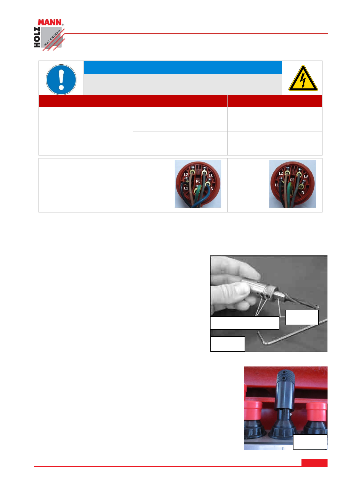
Přípojka 400V:
5-drátů:
s
N-vodičem
4-dráty:
bez
N-vodiče
Obr. 1
závitové šrouby
plocha
Obr. 2
6.3 Nastavení před uvedením do provozu
Veškeré opravy a seřízení při stroji odpojeném od sítě!!!
6.3.1 Instalace / výměna vrtáků
Vrták o hřídelce 10 mm nasaďte do upínacího pouzdra a
pevně přišroubujte.
Utáhněte oba ustavovací šrouby na upínacím pouzdře
pomocí imbus klíče 2,5-mm. Obr. 1.
Vrták nastavíte na požadovanou pomocí závitového
šroubu v hřídelce (viz. Obr. 1).
Stroj disponuje celkem 21 vrtacími vřeteny, které
jsou kódované 2 standardními barvami. Je 11 pravých
(v černém provedení) a 10 levých (v oranžovém
provedení).
Vrtací vřeteno před nasazením do vrtací jednotky řádně
očistěte.
POZOR: Při nasazování nebo vyjímání ostrých vrtáků je
třeba dbát zvýšené opatrnosti.
Nasazení upínacího pouzdra do vřetene:
Ujistěte se, že jsou oba závitové šrouby (Obr. 1) dostatečně
hluboko zašroubovány do upínacího pouzdra.
Nasuňte hřídel upínacího pouzdra na vrtací vřeteno.
Obr. 3.
Zatlačte upínacím pouzdrem mírným otočením vlevo / vpravo -
na vrtací vřeteno, dokud nezapadne. Obr. 3
HOLZMANN MASCHINEN GmbH www.holzmann-maschinen.at Strana 13
KOLÍKOVAČKA / SINGLE-RAW MULTI-BORING MACHINE DBM 21N
Page 14
Obr. 3
Obr. 5
Obr. 6
Pro kontrolu, zda-li jsou všechny vrtáky v požadované délce můžete
položit profilovou lištu na hroty vrtáků.
Nepřesnosti srovnejte doseřízením nebo nahrazenám jinými vrtáky.
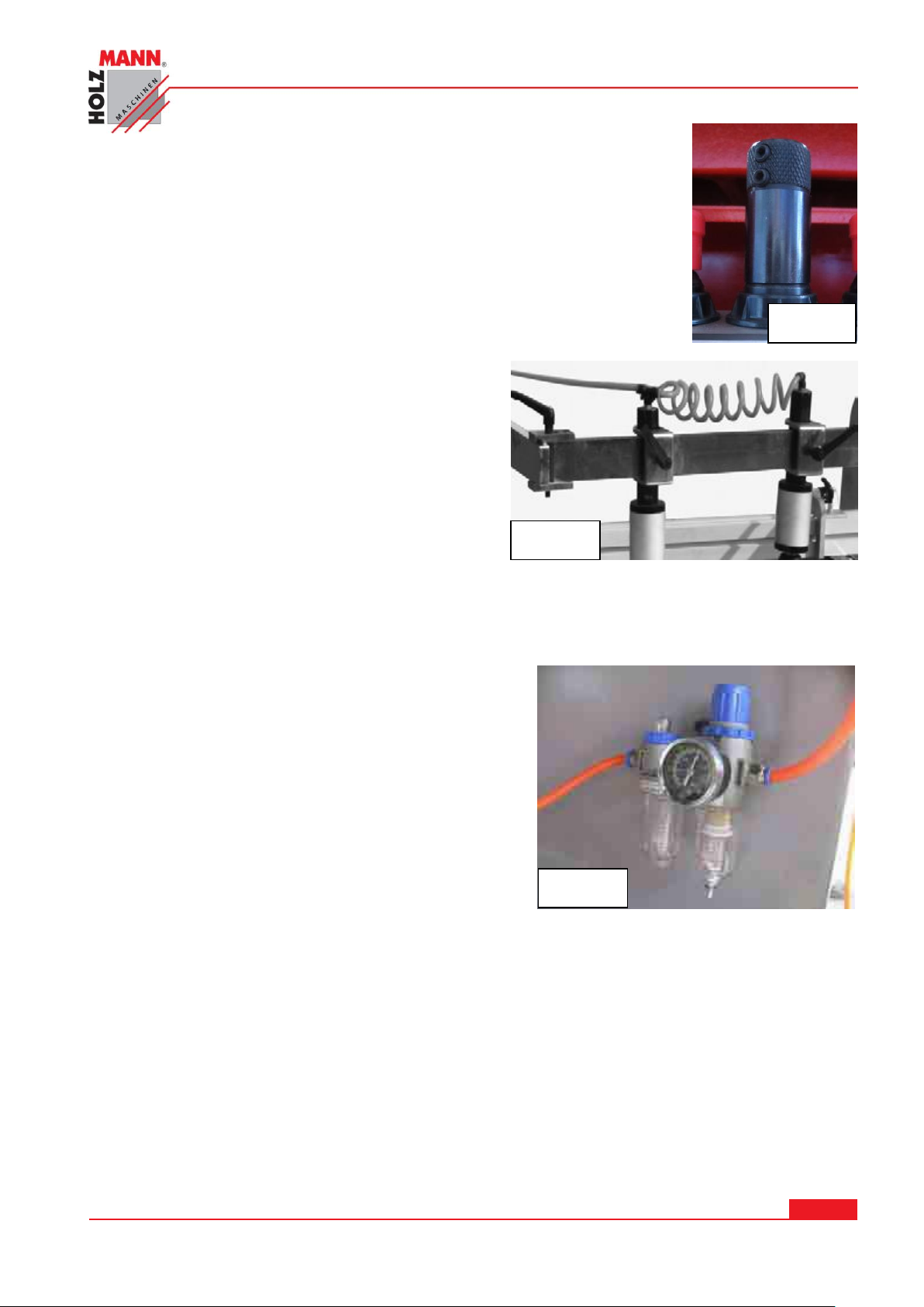
6.3.2 Montáž hadice tlakového
vzduchu
Nasaďte dlouhou hadici tlakového vzduchu na
Y-spojku. Obr. 5
Krátký díl propojte z Y-spojky na 2. pneumatický
přítlačný válec.
6.3.3 Montáž redukčního ventilu
VÝSTRAHA
Ujistěte se, že je spínač 11 –ovládací pult - v nulové
poloze, aby se vrtací jednotka nerozjela.
Napojte hadici tlakového vzduchu na redukční
ventil. Obr. 6
Nyní lze tlakovou hadici připojit ke kompresoru nebo
jiný zdroj tlakového vzduchu.
Zkontrolujte na manometru tlak, který by měl být v
rozsahu 6 - 8 barů, popřípadě ho pomocí regulátoru
nastavte.
POZOR:
Stroj nesmíte uvést do provozu dříve, než bude manometr ukazovat správný tlak v rozsahu cca 6-8
barů. Jiné nastavení tlaku může vést k poškození stroje.
HOLZMANN MASCHINEN GmbH www.holzmann-maschinen.at Strana 14
KOLÍKOVAČKA / SINGLE-RAW MULTI-BORING MACHINE DBM 21N
Page 15
6.3.4 Vrtací jednotka: Nastavení 90 stupňů
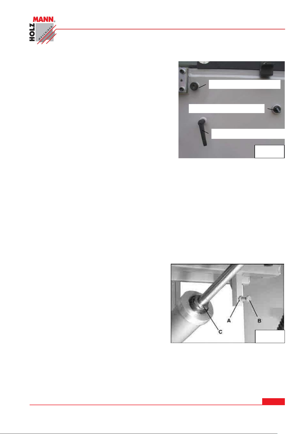
Kolík zajištění úhlu
Přepínač pro 0 – 90°
Aretační páka
Obr. 7
Obr. 8
Pro otočení vrtací jednotky z vertikální polohy do
horizontální postupujte následovně:
Ujistěte se, že je vrtací jednotka zcela zasunutá – v
základní poloze.
Povolte aretační páku otočením proti směru chodu
hodinových ručiček) Obr. 7.
Vytáhněte kolík zajištění úhlu z otvoru.
Přepínač 0 – 90° otočte do horizontální polohy.
VÝSTRAHA
Vrtací jednotka se po spuštění může velice rychle pohybovat nahoru nebo dolů.
Proto je nutné udržet určitý odstup od vrtací jednotky při jejím spuštění!
Až vrtací jednotka dosáhne horizontální polohy, utáhněte aretační páku.
Aretační páka by měla být vždy utáhnutá, kromě situace při sklopení vrtací hlavy.
6.3.5 90 stupňový doraz
Nastavení 90-stupňů pro vrtací jednotku je továrně nastaveno a nemělo by být nutné žádné
doseřizování.
Pokud však bude seřízení přesto třeba, postupujte následovně:
Otevřte přední a zadní dvířka.
Povolte šestihrannou matku A (Obr. 8)
Otáčejte dorazovým šroubem B dokud nebude
vrtací jednotka ustavena přesně na 90 stupňů.
Zakontrujte šroub A.
6.3.6 Horizontální doraz
Horizontální doraz vrtací jednotky se nastaví pomocí matky na válci C (Obr. 8). Motka reguluje,
jak daleko se vysune píst a tím řídí, kde se vrtací jednotka zastaví, když se dosáhne horizontální
polohy.
Otáčejte šestihrannou matkou tak dlouho, dokud nebude vrtací jednotka na 0-stupni v
horizontální poloze.
HOLZMANN MASCHINEN GmbH www.holzmann-maschinen.at Strana 15
KOLÍKOVAČKA / SINGLE-RAW MULTI-BORING MACHINE DBM 21N
Page 16
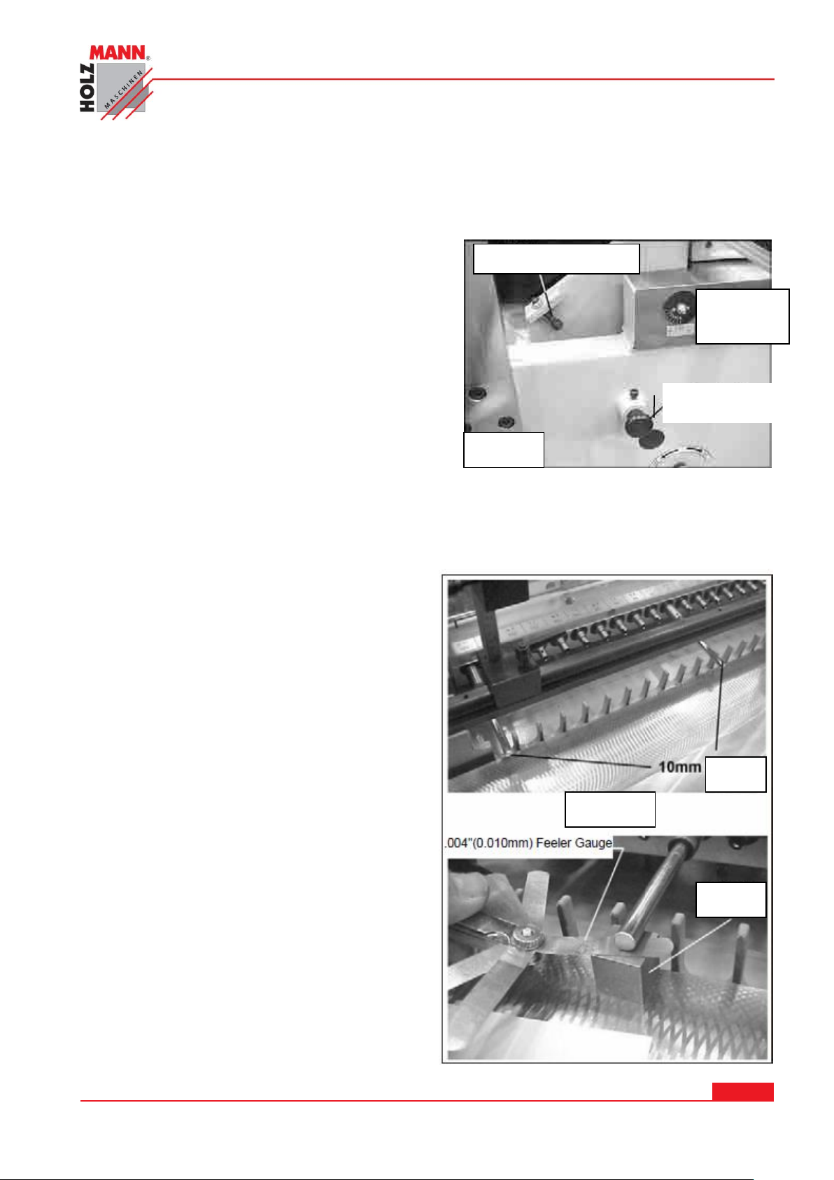
6.3.7 45 stupňový doraz
Kolík zajištění
úhlu
Dorazový šroub
úhlová
stupnice
Obr. 9
Obr. 11
kalibr
kolík
Nastavení 90-stupňů pro vrtací jednotku je továrně nastaveno a nemělo by být nutné žádné
doseřizování.
Pokud však bude seřízení přesto třeba, postupujte následovně:
Kolík zajištění úhlu (Obr. 9) musí být zcela
zatlačený. (Povolte kontramatku na dorazovém
šroubu.
Otáčejte dorazovým šroubem, dokud nedosáhne
úhlu 45 stupňů. Toto nastavení zkontrolujte
pomocí natáčení vrtací jednotky dolů, dokud
dorazový šroub nedolehne na kolík zajištění úhlu.
Úhel můžete odečíst na úhloměru.
Kontramatku opět zakontrujte na dorazovém
šroubu.
Při použití 45-stupňového dorazu, vždy
utáhněte aretační páku (Obr. 7).
6.3.8 Paralelita vrtací jednotky s plochou pracovního stolu
Pro zajištění přesného středu vrtaného otvoru na obrobku, musí být línie vřeten paralelně k desce
stolu. Kontrolu proveďte následovně:
Vyndejte vrtáky z vřeten.
Umístěte vrtací jednotku do horizontální
polohy a polohu zajistěte.
Otáčejte vrtací jednotkou pomocí ruční kliky
co nejblíže k povrchu stolu.
Nasaďte 10 mm kolík -cca 115 mm dlouhý-
do prostředního vřetene. Obr. 11
Umístěte kalibr na stůl pod kolík.
Použijte 0,01 mm spárovou měrku, kterou
položte na horní stranu kalibru a spusťe
vřetena otáčením ruční kliky pro výškové
ustavení, dokud se kolík nedotkne spárové
měrky. Obr. 11.
Spárovou měrku by mělo být možné lehce
vytáhnout.
Vrtací jednotku zablokujte v této poloze
pomocí utažení aretační páky.
HOLZMANN MASCHINEN GmbH www.holzmann-maschinen.at Strana 16
KOLÍKOVAČKA / SINGLE-RAW MULTI-BORING MACHINE DBM 21N
Page 17
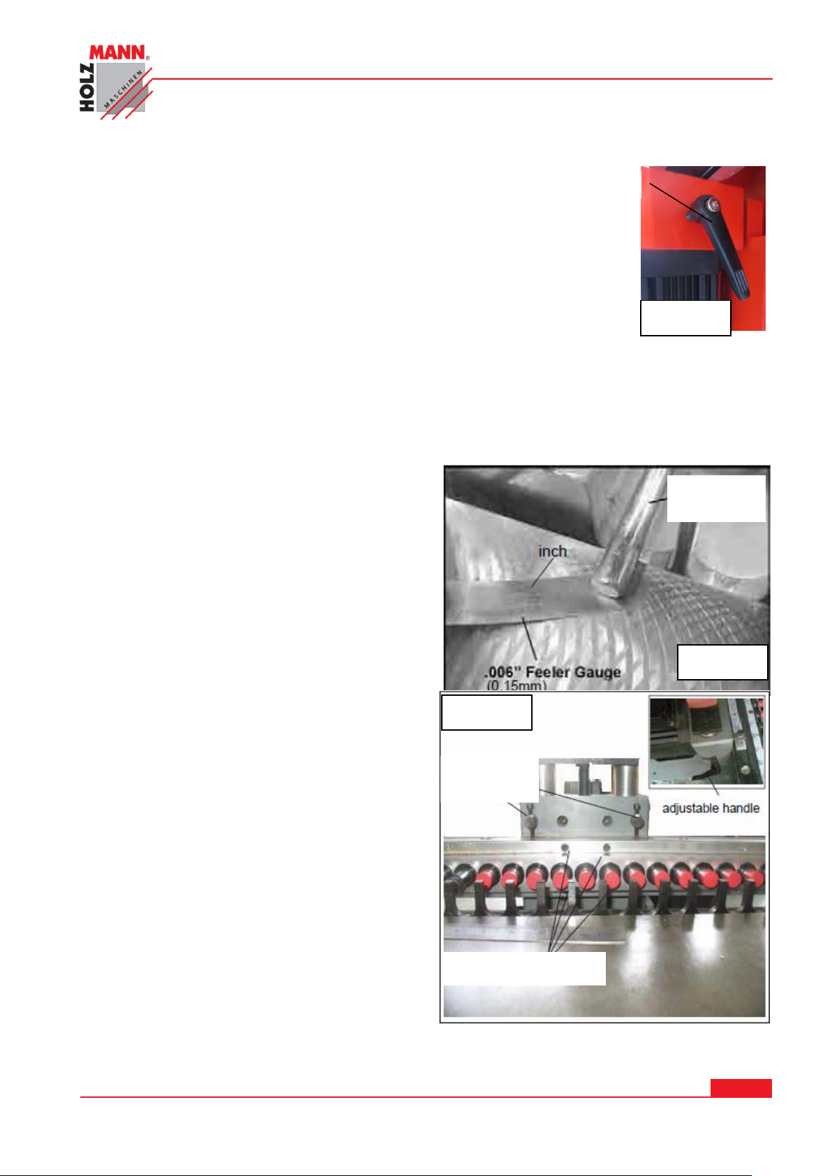
Nasaďte 10 mm kolík -cca 115 mm dlouhý- do prostředního vřetene. Obr. 11.
Aretační páka
Obr. 12
Obr. 14
seřizovací šrouby
Einstell-
Schraube
10 mm
kolík
Obr. 13
ustavovací
šrouby
Sejměte upínací pouzdro s vřetenem z centrálního vřetene a instalujte ho
na pravé vřeteno.
Použijte kalibr a spárovou měrku pro kontrolu výšky krajních vřeten
stejným postupem, jako jste kontrolovali prostřední vřeteno. Oba konce
vřeten by měly mít shodnou výšku jako prostřední vřeteno. Pokud tomu
tak není, povolte čtyři upevňovací šrouby podle obr. 14. Přenastavte
trochu dva ustavovací šrouby, dokud se nebude výška vřeten shodovat.
Až se bude výška vřeten shodovat, utáhněte opět všechny čtyři upevňovací šrouby.
Ponechte 10mm ocelové kolíky ve vřetenech pro další nastavování.
Zajistěte vrtací jendotku v této poloze utažením aretační páky na držáku motoru.
Sejměte upínací pouzdro s vřetenem z
centrálního vřetene a instalujte ho na pravé
vřeteno.
Použijte kalibr a spárovou měrku pro kontrolu
výšky krajních vřeten stejným postupem, jako
jste kontrolovali prostřední vřeteno. Oba
konce vřeten by měly mít shodnou výšku jako
prostřední vřeteno. Pokud tomu tak není,
povolte čtyři upevňovací šrouby podle Obr.
14. Přenastavte trochu dva ustavovací
šrouby, dokud se nebude výška vřeten
shodovat.
Až se bude výška vřeten shodovat, utáhněte
opět všechny čtyři upevňovací šrouby.
HOLZMANN MASCHINEN GmbH www.holzmann-maschinen.at Strana 17
KOLÍKOVAČKA / SINGLE-RAW MULTI-BORING MACHINE DBM 21N
Page 18
7 PROVOZ
Obr. 10
Deska dorazu
Aretační páka
Obr. 4
7.1 Obsluha
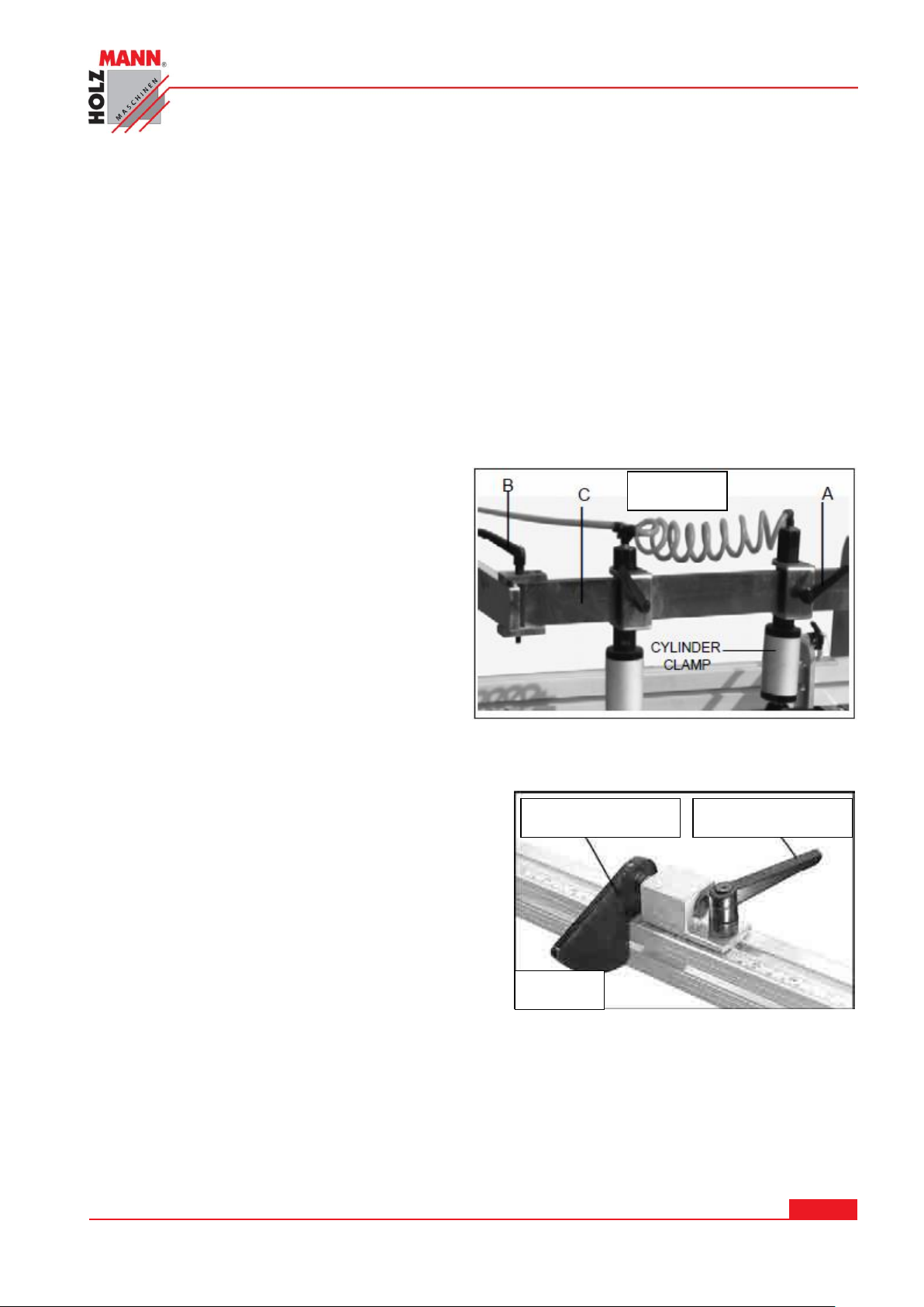
7.1.1 Variabilní poloha přítlačného válce
Obrobek je během provozu na plochu stolu připevněn pomocí upínacího systému. Upínací systém
lze variabilně nastavovat.
Horizontální nastavení: Povolte aretační páky A (Obr. 10)
Posuňte svorky na libovolné místo na profilu C. Jakmile budou svorky správně ustaveny v
požadované poloze, utáhněte na nich aretační páky A.
Vertikální vyrovnání: Svorky lze nastavit i vertikálně, aby bylo možné přizpůsobit jejich výšku
tloušťce obrobku. Povolte aretační páku A (Obr. 10) a posunujte pneumatický přítlačný válec
nahoru nebo dolů do požadované polohy.
Zajistěte upínací válec utažením aretační páky
A.
Paralelní nastavení: Celý profil C lze
kompletně přesunout.
Povolte obě aretační páky B (Obr. 10) a
posuňte nosník dozadu nebo dopředu podle
potřeby.
Nastavenou polohu profilu/nosníku zajistěte
utažením aretačních pák B.
7.1.2 Nastavení sklopného dorazu
Instalujte sklopný doraz na konci pravítka
(profilu) podle Obr. 4.
Sklopný doraz lze libovolně posouvat po profilu a
utažením aretační páky zajistit jeho pozici. Pokud
není sklopný doraz potřeba, lze desku dorazu
odklopit nahoru.
VÝSTRAHA: Veškeré aretační páky lze vytažením
nahoru a otočením vysunout z dráhy.
HOLZMANN MASCHINEN GmbH www.holzmann-maschinen.at Strana 18
KOLÍKOVAČKA / SINGLE-RAW MULTI-BORING MACHINE DBM 21N
Page 19
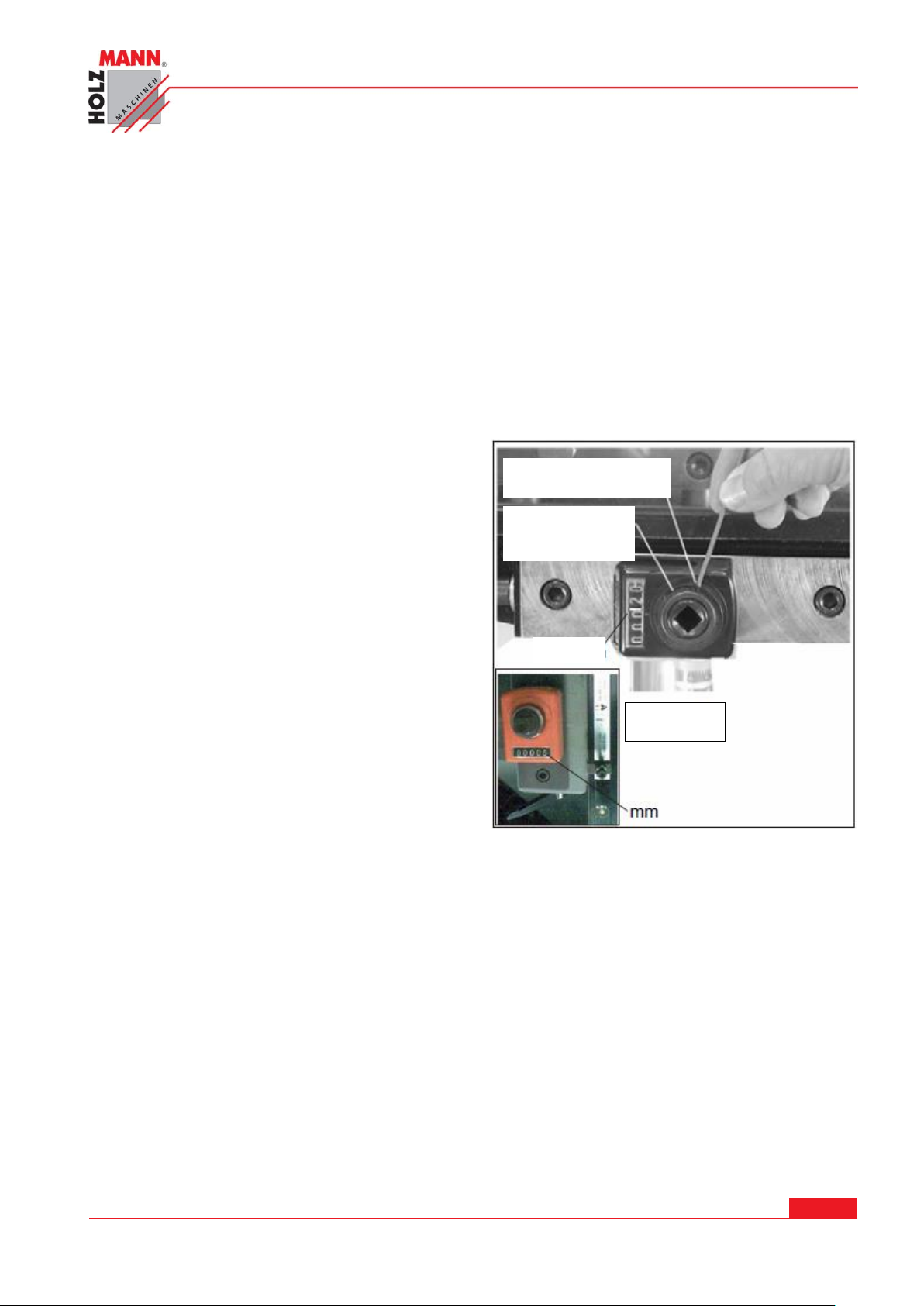
7.1.3 Nastavení digitálního ukazatele na nulu
Obr. 15
Ustavovací
kroužek
Závitový šroub
Když je středová linie vřeten vyrovnáná s povrchem stolu, lze ukazatel na mechanickém
digitálním ukazateli nastavit na nulu.
Mezera 5 mm od osy (středu) ocelového kolíku k povrchu stolu musí být připočtena. Z tohoto
důvodu musí být digitální ukazatel příslušně nastaven.
Povolte šroub (Obr. 15) pomocí imbusového klíče 2,5 mm. Otáčejte ustavovacím kroužkem,
dokud se na displeji nezobrazí 5 mm.
Nyní utáhněte ustavovací kroužek se závitovým šroubem.
Digitální ukazatel bude nyní v závislosti na ploše stolu správně zkalibrovaný na "nulu".
HOLZMANN MASCHINEN GmbH www.holzmann-maschinen.at Strana 19
KOLÍKOVAČKA / SINGLE-RAW MULTI-BORING MACHINE DBM 21N
Page 20
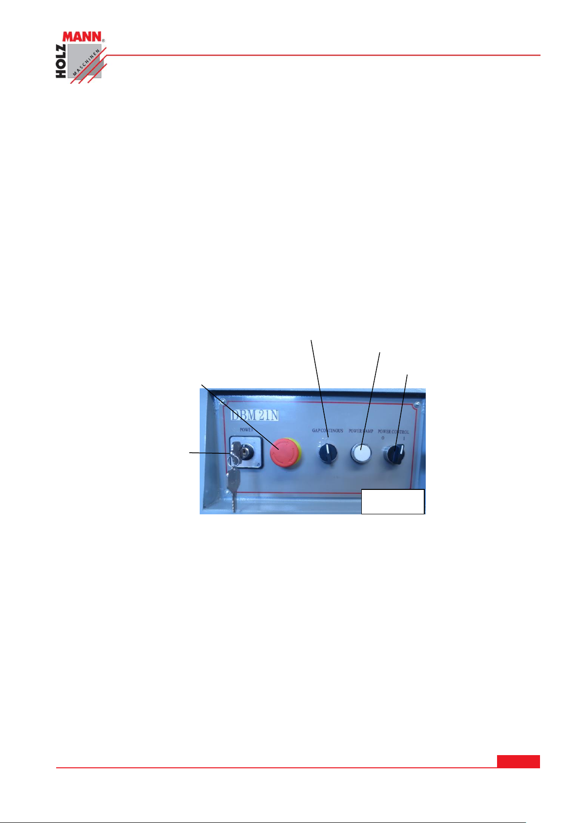
7.1.4 Spuštění / Zastavení stroje
Obr. 16
NOUZOVÝ
vypínač
Hlavní vypínač
Vertikalní /
Horizontalní přepínač
Kontrola provozu
ZAPNUTO / VYPNUTO
Hlavní vypínač otočený vlevo se nachází v poloze ˝I˝.
Přepněte pravé tlačítko do polohy ˝I˝.
Sešlápněte nožní pedál pro ovládání stroje. Ten aktivuje přítlačné válce a vrtací jednotku.
Vrtací jednotka najede přímo k obrobku a provede vrtání.
Při nastavení omezení hloubky vrtání koncovým spínačem se vrtací jednotka vrátí okamžitě
zpět do výchozí polohy.
Přítlačné válce zajedou a obrobek je možné posunout nebo úplně odebrat.
VÝSTRAHA: Vrtáky zůstanou v obrobku tak dlouho, dokud bude aktivovaný/sešlápnutý nožní
pedál.
Pro zastavení přepněte pravé tlačítko do polohy ˝O˝.
ZAPNUTO / VYPNUTO – Spouští a zastavuje stroj během operace vrtání přepnutím pravého
tlačítka do polohy ˝O˝
Vertikální / horizontální – pohybuje vrtací jednotkou buď ve vertikální nebo horizontální
poloze.
Kontrolka provozu - svítí, pokud je stroj v provozu.
NOUZOVÝ vypínač
Při aktivaci se stroj okamžitě zastaví.
Pro odjištění aktivovaného nouzového vypínače jím otočte ve směru šipky a lehce vytáhněte.
HOLZMANN MASCHINEN GmbH www.holzmann-maschinen.at Strana 20
KOLÍKOVAČKA / SINGLE-RAW MULTI-BORING MACHINE DBM 21N
Page 21
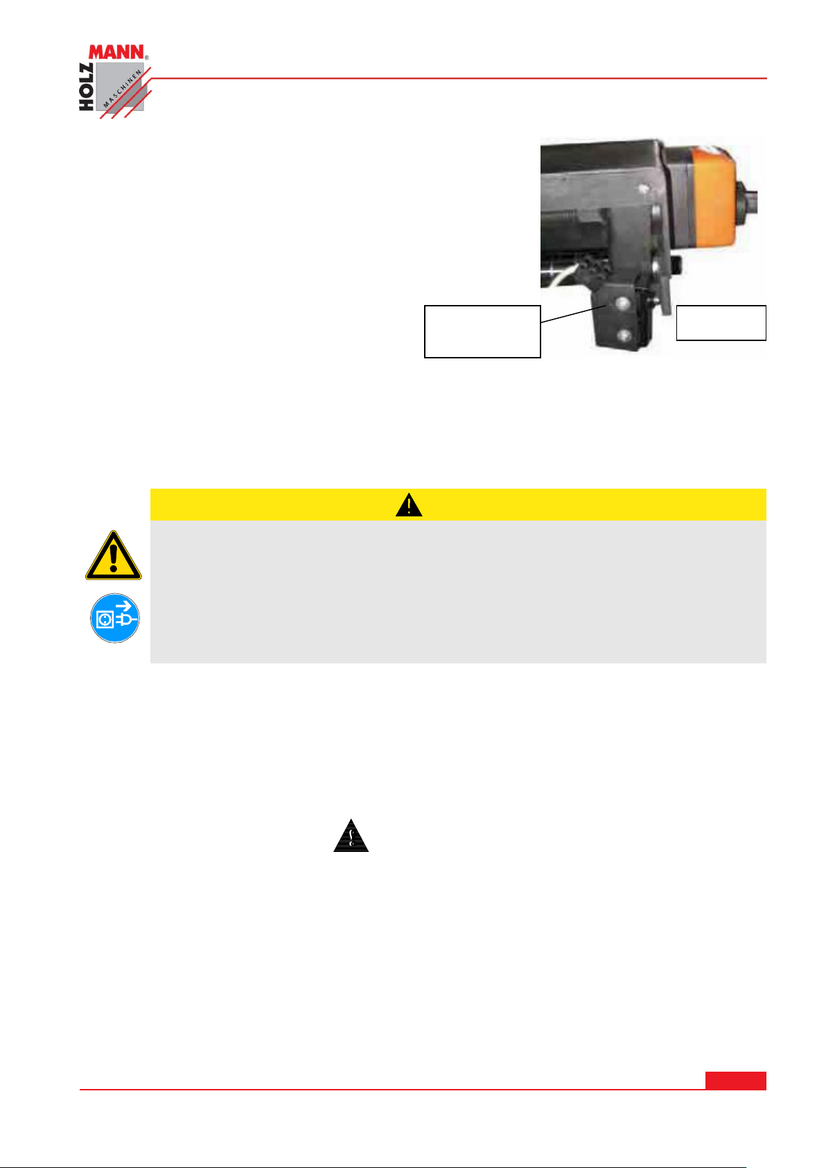
Koncový spínač – Koncový spínač je namontovaný pod vrtací
POZOR
Čištění a údržbu provádějte vždy při vypnutém stroji:
Při nežádoucím spuštění stroje hrozí poškození nebo zranění!
Platí:
Před započetím úkonů údržby stroj vypněte a odpojte od přívodu elektrického proudu
Koncový
spínač
Obr. 17
jednotkou u digitálního ukazatele (Obr. 17).
Pomocí ruční kliky lze na digitálním ukazateli nastavit
požadovanou hloubku.
Když vrtací jednotka dosáhne nastavené hloubky, zajede zpět
do své výchozí polohy.
8 ÚDRŽBA
Stroj je téměř bezúdržbový a je pouze několik málo částí, které musí být obsluhou
ošetřeny.
Poruchy nebo závady, které mohou ovlivnit bezpečnost, nechte okamžitě odstranit.
Opravy mohou být prováděny pouze kvalifikovaným opravářem! Úplné a správné čištění stroje
zaručuje dlouhou životnost stroje a představuje předpoklad bezpečné práce se strojem.
Po každé pracovní směně musí být stroj a všechny jeho části řádně očištěny.
Pravidelně kontrolujte, zda-li jsou výstražné a bezpečnostní štítky a samolepy na stroji
v bezvadném a čitelném stavu.
Před každým použitím stroje zkontrolujte bezvadný stav bezpečnostních prvků.
Uskladnění stroje je možné pouze v suchém prostředí a musí být zajištěn proti vlivu počasí.
Před prvním uvedením stroje do provozu, a následně každých 100 motohodin, je nutné
aplikovat tenkou vrstvu oleje nebo mazacího tuku na všechny pohyblivé části a jejich spoje
(pokud je to potřeba, před mazáním očistěte kartáčem od pilin a prachu).
HOLZMANN MASCHINEN GmbH www.holzmann-maschinen.at Strana 21
KOLÍKOVAČKA / SINGLE-RAW MULTI-BORING MACHINE DBM 21N
Page 22
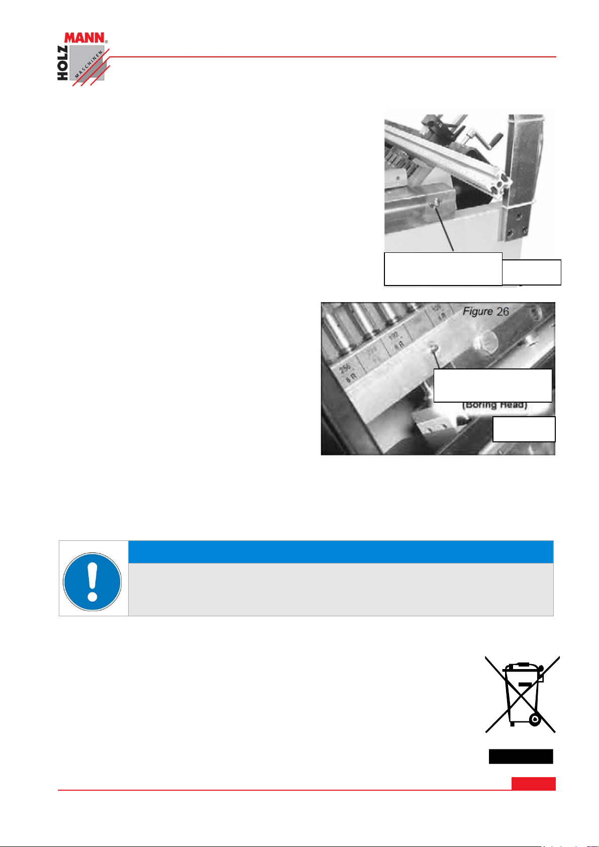
8.1 Mazání
VÝSTRAHA
Použití čistících prostředků jako rozpouštědel, agresivních chemikálií
nebo abrasivních prostředků má za následek poškození stroje!
Platí: Při čištění používejte vodu a v případě nutnosti jemné čističe!
Obr. 17
Mazací hlavice
Mazací hlavice
Obr. 18
Příležitostné otření tyček pneumatického válce je součástí
údržby.
Rovněž, pokud jsou značné usazeniny prachu, špíny nebo
dřevěných pilin na místech k opracování.
Namažte vrtací jednotku pomocí dvou maznic na protilehlých
stranách rámu po jeho sklopení (Obr. 17).
Namažte ozubená kola uvnitř vrtací jednotky pomocí obou
mazacích hlavic na zadní straně vrtací jednotky (Obr. 18)
8.2 Čištění
Po každém použití musí být stroj a jeho součásti řádně očištěny.
Stroj zbavte vždy po práci od dřevěného prachu a zbytků dřeva a pilin z vrtání.
Nelakované povrchy stroje ošetřete proti korozi běžně dostupným antikorozním prostředkem.
8.3 Likvidace
Váš stroj nevyhazujte do komunálního odpadu. Kontaktujte místní orgány pro získání
informací o správné likvidaci a dostupných možnostech likvidace odpadu. Pokud si
u vašeho obchodníka zakoupíte nový nebo podobný stroj, je tento povinen starý
stroj od vás bezplatně převzít k odborné likvidaci.
HOLZMANN MASCHINEN GmbH www.holzmann-maschinen.at Strana 22
KOLÍKOVAČKA / SINGLE-RAW MULTI-BORING MACHINE DBM 21N
Page 23
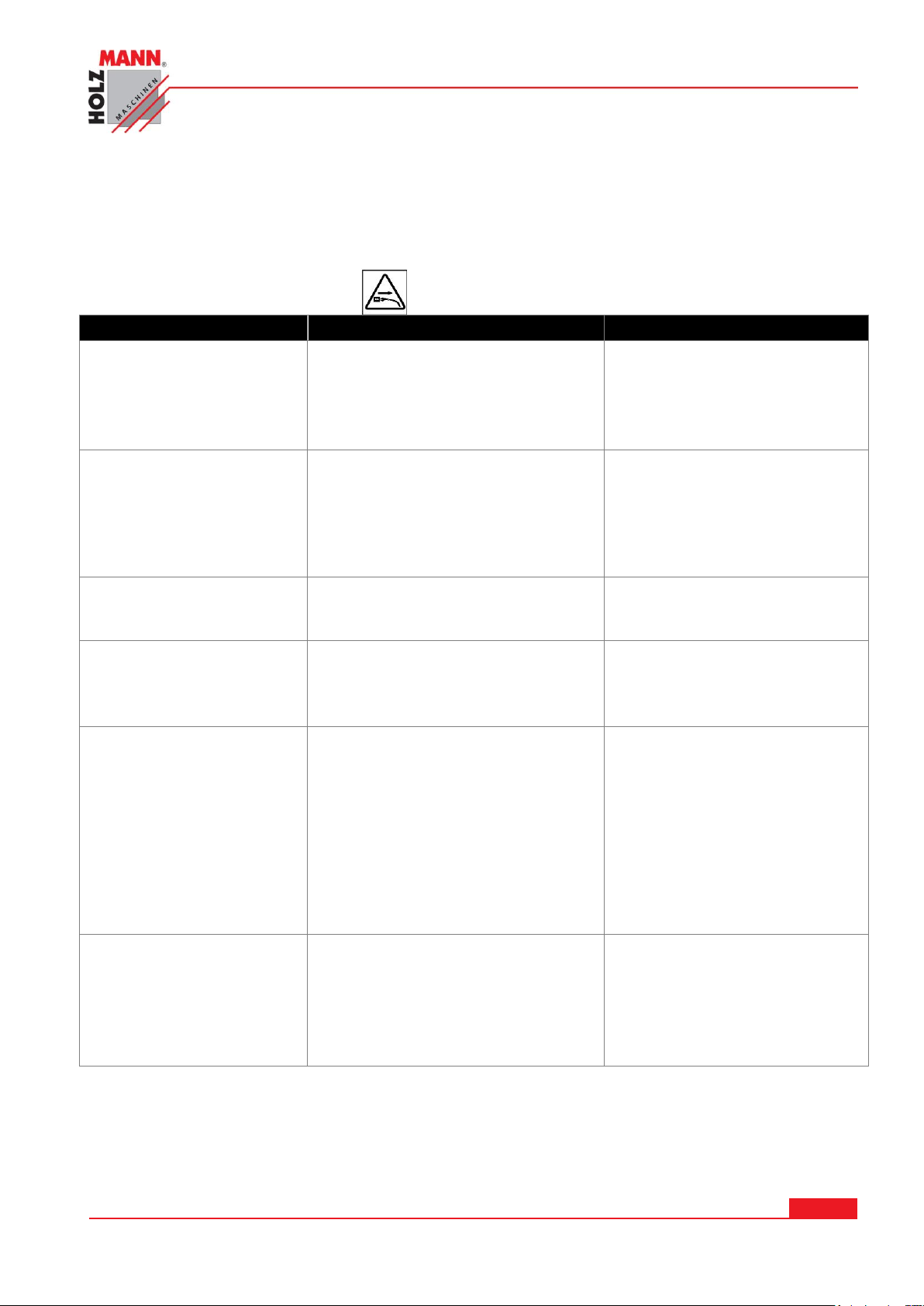
9 ODSTRAŇOVÁNÍ ZÁVAD
Závada
Možná příčina
Odstranění
Stroj nenaběhne
Není připojený ke zdroji
elektrického proudu
Spálená pojistka nebo aktivovaný
ochranný spínač
Poškozený přívodní kabel
Zkontrolujte zapojení.
Vyměňte pojistku nebo
deaktivujte spínač
Kabel vyměňte za bezvadný
Rychlost vrtáku není
dostatečná;
Stroj má příliš málo
proudu
Posuv není správně nastavený
Prodlužovací kabel je příliš slabý
nebo příliš dlouhý
Slabý přívod proudu
Nastavte regulaci posuvu
Nahraďte kabalem o
dostatečném průřezu a
správné délce
Kontaktujte kvalifikovaného
elektrikáře
Po vrtání se vrtací
jednotka nevrátí do
polohy
Poškozený nastavitelný
odvzdušňovací ventil
Vyměňte odvzdušňovací
ventil
Po vrtání se
pneumatický válec
nezasune
Poškozený nastavitelný
odvzdušňovací ventil
Kroužek ve svorce
pneumatického válce je zlomený
Vyměňte odvzdušňovací
ventil
Kroužek / Svorku vyměňte
Vrtací jednotka bez
pohonu
Vzduchová hadice je natržená /
prasklá
Regulační ventil otáček příliš
nízko
Netěsnost přívodu tlakového
vzduchu nebo pneumatického
válce
Koncový spínač je vadný
Nožní pedál mimo provoz
Vyměňte vzduchovou hadici
Povolte regulační ventil
otáček
Opravte nebo vyměňte
pneumatický válec
Vyměňte koncový spínač
Vyměňte nožní spínač
Při vrtání se objevuje
kouř
Dřevo je mokré
Vrtáky jsou tupé
Tlak vzduchu je nedostatečný
Použijte suchý obrobek
Vrtáky nabruste nebo je
vyměňte za nové
Optimální nastavení tlaku
vzduchu je cca 6 – 8 barů
PŘED ZAPOČETÍM PRÁCE NA ODSTRAŇOVÁNÍ ZÁVAD ODPOJTE STROJ OD SÍTĚ.
HOLZMANN MASCHINEN GmbH www.holzmann-maschinen.at Strana 23
KOLÍKOVAČKA / SINGLE-RAW MULTI-BORING MACHINE DBM 21N
Page 24
10 PREFACE
HOLZMANN MASCHINEN GmbH
A-4170 Haslach, Marktplatz 4
Tel 0043 7289 71562 - 0
Fax 0043 7289 71562 - 4
Dear Customer!
This manual contains information and important instructions for the installation and correct use of
the mortising machine DBM 21N.
Following the usual commercial name of the device (see cover) is substituted in this manual with
the name "machine".
This manual is part of the product and shall not be stored separately from the product. Save it for
later reference and if you let other people use the product, add this instruction manual to the
product.
Please read and obey the security instructions!
Before first use read this manual carefully. It eases the correct use of the product and
prevents misunderstanding and damages of product and the user’s health.
Due to constant advancements in product design, construction pictures and content may diverse
slightly. However, if you discover any errors, inform us please.
Technical specifications are subject to changes!
Please check the product contents immediately after receipt for any eventual transport
damage or missing parts.
Claims from transport damage or missing parts must be placed immediately after initial
product receipt and unpacking before putting the product into operation.
Please understand that later claims cannot be accepted anymore.
Copyright
© 2014
This document is protected by international copyright law. Any unauthorized duplication,
translation or use of pictures, illustrations or text of this manual will be pursued by law – court of
jurisdiction is A-4020 Linz, Austria!
Customer service contact
HOLZMANN MASCHINEN GmbH www.holzmann-maschinen.at Strana 24
KOLÍKOVAČKA / SINGLE-RAW MULTI-BORING MACHINE DBM 21N
Page 25
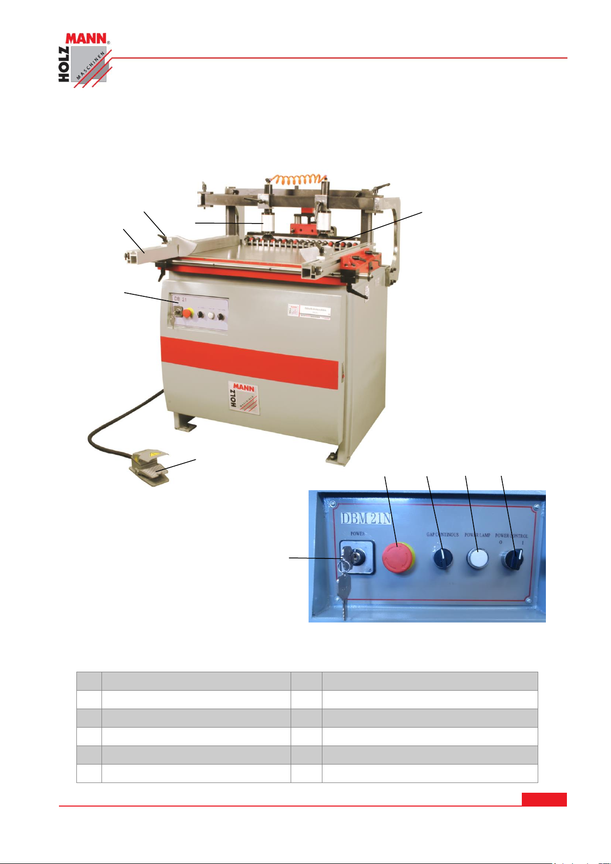
11 TECHNIC
1
Control panel
7
Main switch
2
Stop rail
8
EMERGENCY STOP switch
3
Folding stopper -Stop plate-
9
Vertical / horizontal switch
4
Clamping cylinder
10
Operation lamp
5
Boring head
11
Drill spindle motor ON / OFF
6
Foot pedal switch
4
2 5 1
6 3 8
7 9 10
11
11.1 Main components
11.2 Controls
HOLZMANN MASCHINEN GmbH www.holzmann-maschinen.at Strana 25
KOLÍKOVAČKA / SINGLE-RAW MULTI-BORING MACHINE DBM 21N
Page 26
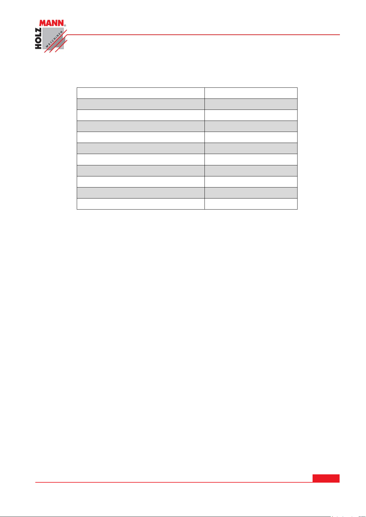
11.3 Technical Details
Mains voltage
400V
Engine power (S1 100%) (S6)
1,5 / 2,1 kW
number of spindles
21
Distance between centers
32mm
Distance between first and last spindle
640mm
max. drilling depth
50mm
Spindle speed
2840 min-1
table dimensions
870x550mm
Compressed air connection
6 – 8 bar
Dimensions l x w x h
1100x1000x1000mm
Weight
342kg
Moisture
max. 90%
Temperature
from +1°С
to +40°С
Height above sea level
max. 2000 m
12 SAFETY
12.1 Intended use
The machine may be, safety and danger, and only in perfect working condition for its intended
purpose! Disorders, which may affect the safety must be rectified immediately!
It is generally prohibited to modify safety equipment of the machine or to make ineffective!
The person operating the machine must operate standing from the front.
The single-raw multi-boring machine DBM 21N is used exclusively for drilling dowel holes in wood
materials.
The machine is intended for the work under the following conditions:
The machine is not intended for outdoor use.
The machine is not designed for operation in potentially hazardous conditions.
12.2 Intended Use
The operation of the machine under conditions outside the above limits is not permitted.
The operation of the machine without the proposed protective devices is not permitted;
dismantling or disable the protective devices is prohibited.
It is not permitted the operation of the machine with materials that are not expressly stated in
this manual.
HOLZMANN MASCHINEN GmbH www.holzmann-maschinen.at Strana 26
KOLÍKOVAČKA / SINGLE-RAW MULTI-BORING MACHINE DBM 21N
Page 27
It is not permitted machining of materials with dimensions outside the limits specified in this
Work area and keep soil around the machine clean and free of oil, grease and
residues of material!
Provide adequate lighting in the work area of the machine!
The machine does not use outdoors!
In fatigue, lack of concentration or under the influence of drugs, alcohol or drugs,
the work on the machine is prohibited!
Wood dust may contain chemical substances that have a negative impact on
personal health. Work on the machine only in well-ventilated areas with appropriate
dust mask to perform!
The running machine should never be left unattended! Turn off the machine before
leaving the work area and wait until the machine is at a standstill!
Before maintenance or adjustments, the machine must be disconnected from the
power supply! Switch off the main switch before disconnecting the power (OFF).
Use the power cord never for transport or manipulation of the machine!
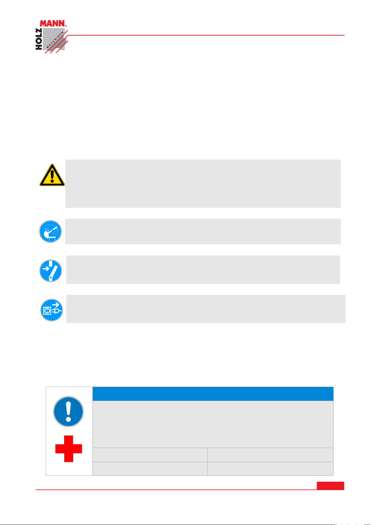
NOTICE
Emergency procedure
A first aid kit in accordance with DIN 13164 should always be readily
available for a possible accident. Initiate the violation in accordance with
the necessary first aid measures. When requesting support, provide the
following details:
1. Place of accident
2. Type of accident
3. Number of injured people
4. Injury type(s)
manual.
It is not permitted the use of untested tools that are not relevant EN standards for labor safety
and that are not intended for the drill diameter.
Any changes in the design of the machine is not permitted.
12.3 General Safety
Warning labels and / or stickers on the machine that are illegible or removed shall be
replaced immediately!
To avoid malfunctions, damage and physical injury MUST be observed:
On the device there are only few of them serviceable components. It is not necessary to
dismantle the machine.
Have repairs carried out only by an expert!
Accessories: Only use of HOLZMANN Accessories!
If you have any questions and problems to our customer service.
HOLZMANN MASCHINEN GmbH www.holzmann-maschinen.at Strana 27
KOLÍKOVAČKA / SINGLE-RAW MULTI-BORING MACHINE DBM 21N
Page 28

12.4 Safety equipment of DBM 21N
In construction of the machine, the following protective devices are provided:
EMERGENCY STOP switch. Make sure it is functioning at periodic intervals.
12.5 Residual risks
Also in compliance with all safety regulations and when used properly, the following residual risks
must be observed:
Risk of injury to the hands / fingers through the rotating drill bit during operation.
Risk of injury from contact with live electrical components.
Risk of injury due to breakage or being thrown out of the drill, especially under heavy
congestion.
Hearing damage unless precautions have been taken by the user of hearing protection.
Risk of injury to the eye by flying debris.
Risk of inhalation of toxic wood dust in treated workpieces.
These risks can be minimized if all safety rules are applied, the machine is properly maintained
and serviced the machine as intended and is serviced by a trained service professional.
13 ASSEMBLY
13.1 Delivery content
After receipt of the delivery, if all parts are in order. Report any damage or missing items
immediately to your dealer or the shipping company. Visible damage must also be recorded
without delay in accordance with the provisions of the warranty on the delivery note, otherwise
the goods shall be accepted as properly.
Content:
Single raw multi-boring unit, 400V connector, 4x folding stoppers, winch for drilling depth setting,
2x parallel strokes, open end wrench, 3x hex wrench, 6x Quick-change chuck for drills
13.2 The workplace
Choose a suitable place for the machine;
Observe the safety requirements of Chapter 12 as well as the dimensions of the machine from
Section 11.2
The location selected must ensure as well as the possibility for connection to an extraction system
an appropriate connection to the electrical grid.
Make sure that the floor can support the load of the machine; the machine must be leveled on all
bases simultaneously, so it is perfectly level and stable.
You must also ensure all round a distance of at least 0.8 m around the machine.
13.2.1 Transport
The machine can be transported in package with a forklift.
HOLZMANN MASCHINEN GmbH www.holzmann-maschinen.at Strana 28
KOLÍKOVAČKA / SINGLE-RAW MULTI-BORING MACHINE DBM 21N
Page 29
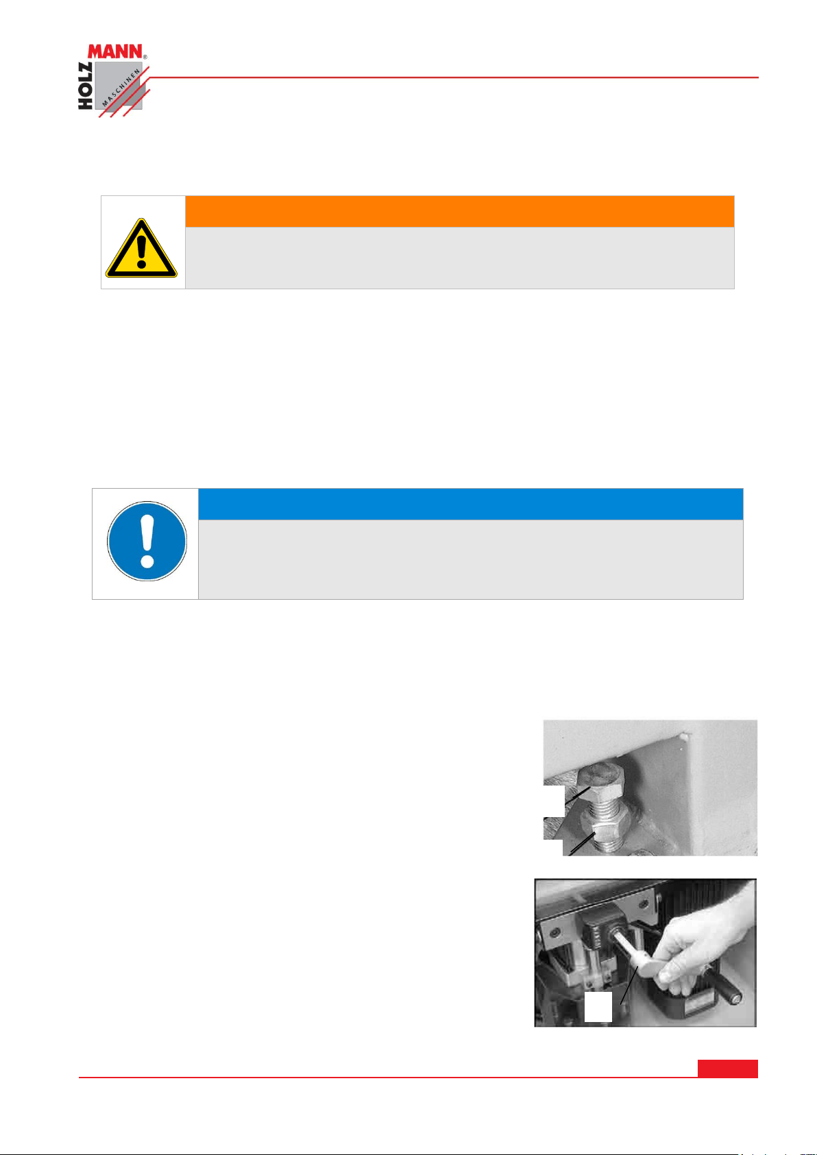
The machine is very heavy. The machine shall be lifted from crate with a suitable lifting device
WARNING
The lifting and transportation of the machine must only be carried
out by qualified staff and must be carried out with appropriate
equipment.
NOTICE
Do not use solvents based on nitrite, aggressive solvents like break
cleaners or scrubbing agents!
These damage the machine surface.
A
B
C
only that is certified to be able to carry the machines load.
Note that lifting equipment used (crane, forklift, sling, etc.) must be in perfect condition.
To maneuver the machine in the packaging can also a pallet jack or a forklift be used.
13.2.2 Preperation of the surface
Uncoated metal machine parts have been insulated with a greasy layer to inhibit corrosion.
This layer has to be removed. You can use standard solvents that do not damage the machine
surface.
13.3 Assembly
The machine itself is delivered pre-assembled. It must only be mounted miter fence, and other
controls on the machine.
Place the machine on firm ground and level.
The nut B is released to the screw A tob e able to rotate to the
desired height.
If the machine is focused on all 4 supports you tighten the
nuts B fixed on all 4 points of view.
The hand crank C for the depth setting is placed on the setting
spindle.
HOLZMANN MASCHINEN GmbH www.holzmann-maschinen.at Strana 29
KOLÍKOVAČKA / SINGLE-RAW MULTI-BORING MACHINE DBM 21N
Page 30
13.4 Power supply
ATTENTION
When working with non-grounded machines:
Severe injury or even death may arise though electrocution!
Therefore: The machine must be operated at a grounded power socket
NOTICE
Operation is only allowed with safety switch against
stray current (RCD max. stray current of 30mA)
NOTICE
Use only permitted extension cable with cross-section
the one in the following table declared.
Voltage
Extension
Cross-section
220 V-240 V
50 Hz
<27 m
1,5 mm
2
<44 m
2,5 mm
2
<70 m
4,0 mm
2
<105 m
6,0 mm
2
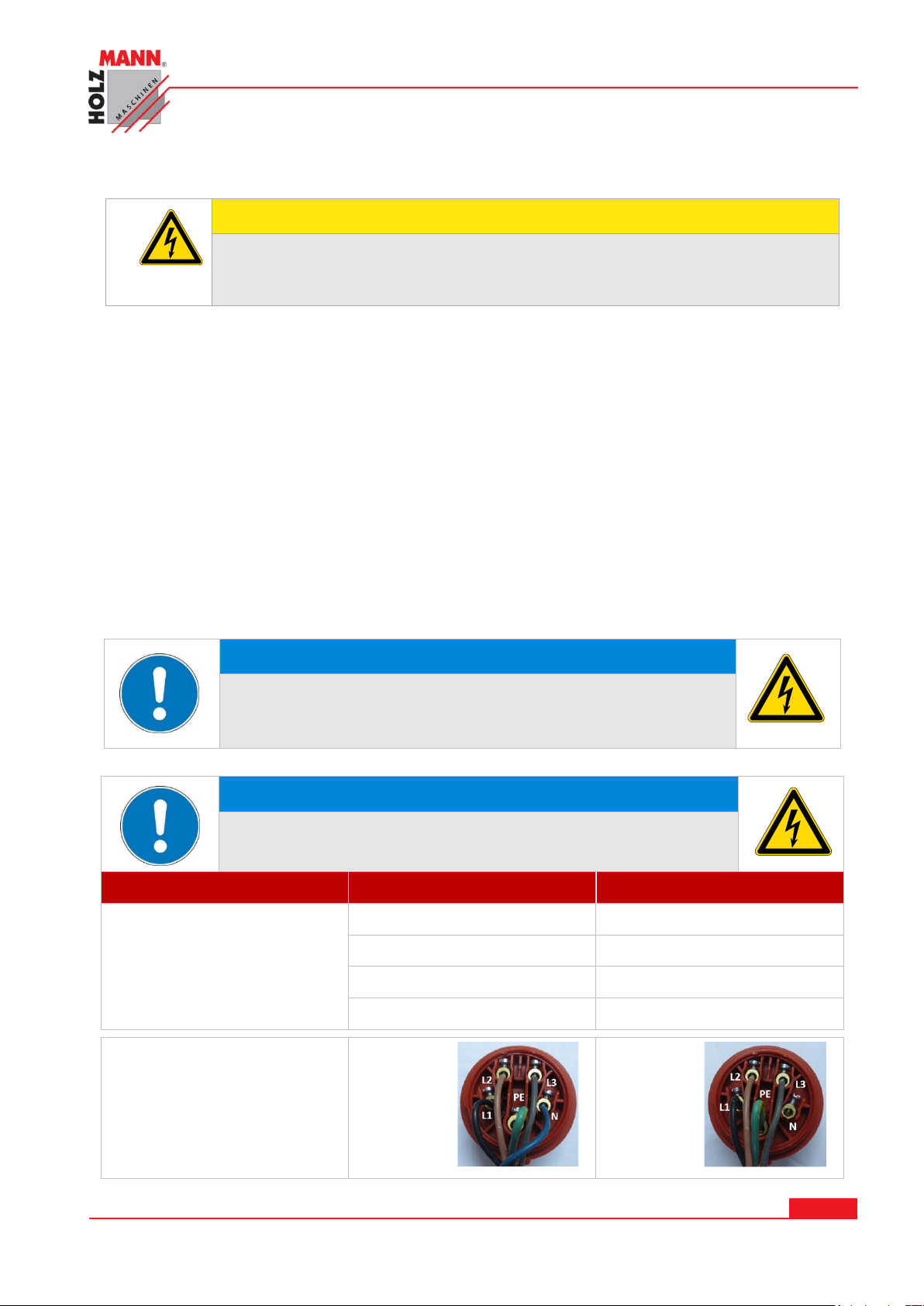
Plug 400V:
5-wire:
with
N-conductor
4-wire:
without
N-conductor
The connection of the machine to the electric power supply and the following checks have to be
carried out by a respectively trained electrician only.
1. The electronic connection of the machine is designated for operation with a grounded
power socket!
2. The connector plug may not be manipulated.
3. he mains supply must be secured with 16A:
4. If the connector plug doesn’t fit or if it is defect, only qualified electricians may modify or
re-new it!
5. The grounding wire should be held in green-yellow.
6. A damaged cable has to be exchanged immediately!
7. Check, whether the feeding voltage and the Hz comply to the required values of the ma-
chine. A deviation of feeding voltage of ±5% is allowed (e.g.: a machine with working
voltage of 380V can work within a voltage bandwidth of 370 till 400V.
8. Make sure that a possible extension cord is in good condition and suitable for the
transmission of power. An undersized cord reduces the transmission of power and heats
up.
9. A damaged cable must be replaced immediately
HOLZMANN MASCHINEN GmbH www.holzmann-maschinen.at Strana 30
KOLÍKOVAČKA / SINGLE-RAW MULTI-BORING MACHINE DBM 21N
Page 31

13.5 Adjustments before operation
Fig. 1
Fig. 3
Fig. 2
13.5.1 Installing / Replacing Boring Bits
Boring bits are to be installed in the chucks, which
are in turn mounted to the spindles of the machine.
The chucks accept boring bits with 10mm shanks.
Thes boring bits will have a screw inside the shank
(see Fig. 1) . This style of boring bit is a available
from the local tools or woodworking stores.
This machine requires a total of 21 boring bits,
which are standard color coded. There should be 11
right-hand bits (black in color) and 10 left-hand bits
(orange in color).
Always wipe clean the shank of the boring bit before
inserting into the chuck.
CAUTION: When installing or removing sharp drills is careful to handle.
Insert chuck spindles:
Make sure that the two screws (Fig. 1) are sufficiently screwed
deep into the chuck.
Slide the shaft of the chuck on the drill spindle. Fig. 2
Press the chuck by turning it slightly left / right on the drill spindle on
until it snaps into place. Fig. 3
To check whether all the drills are in the desired length you can hang up a
profile strip on the drill bits.
The inaccurate drill readjust or replace with new drills.
NOTE: The machine will not operate before the pressure gauge indicates the correct pressure of
approximately 6-8 bar. Other pressure settings can cause damage to the machine
HOLZMANN MASCHINEN GmbH www.holzmann-maschinen.at Strana 31
KOLÍKOVAČKA / SINGLE-RAW MULTI-BORING MACHINE DBM 21N
Page 32
13.5.2 Setting the folding stopper
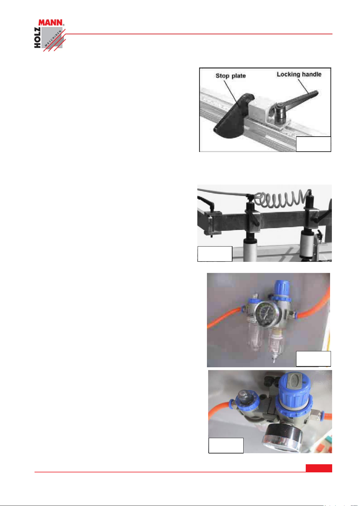
Fig. 4
Fig. 5
Fig. 6
Fig. 7
Mount a fence stop from the end of the fence by
sliding the bolt head at the bottom of the stop
into the top channel of the fence, as shown in
Fig. 4.
The fence stop can be moved to any point along
the fence, and secured by tightening the locking
handle. When not in use, the stop plate can be
flipped upward and out of the way.
NOTE: All locking handles, such as that shown in Fig. 7 can be pivoted out of the way. Simply pull
up on the handle, rotate it to a more convenient position, then release it making sure it seats
itself on the screw.
13.5.3 Attaching Air Hose
Insert the loose end of the long air hose into the
Y-fitting as shown in Fig. 5
Insert on end of the short air hose into the Y-
fitting, and the other end into the I-fitting. See
Fig. 5
13.5.4 Air Supply Connection
WARNING
Make sure the locking handle (see Fig. 6) on the side
of the machine is tightened before connecting the air,
to prevent the boring head from rising suddenly.
Connect your air hose to the nozzle on the
machine´s F.R.L unit, as shown in Fig. 6 . Make
sure your hose fitting is pushed completely onto the
nozzle. Turn on the air.
Check the reading on the pressure gauge – it
should read approximately 6 – 8bar . If the air
pressure is incorrect, adjust it with the regulator
knob (Fig. 7) as follows:
Pull up on the air pressure regulator knob, then
rotate it clockwise to increase the air pressure; or
counterclockwise to decrease the air pressure. Make
this adjustment in small increments and allow the
pressure gauge time to react.
When satisfied, push the regulator knob back down.
(For further adjustments of the air system, see under
“Adjustments”)
HOLZMANN MASCHINEN GmbH www.holzmann-maschinen.at Strana 32
KOLÍKOVAČKA / SINGLE-RAW MULTI-BORING MACHINE DBM 21N
Page 33
WARNING: Do not operate this machine until the pressure gauge shows the correct pressure
Locking handle
Angle pin
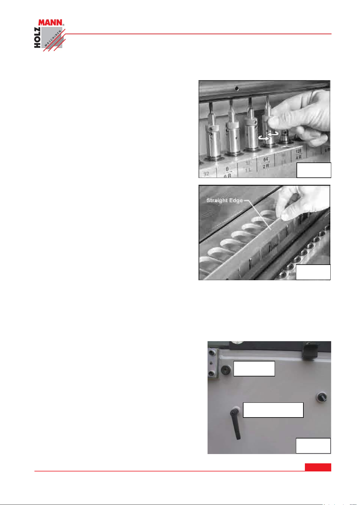
Fig. 9
Fig. 8
Fig. 10
of approximately 6 -8bar . Other pressure settings can cause potential damage to the machine.
CAUTION: Use care when installing or removing
sharp boring bits.
To install boring bits:
1. Make sure the two set screws ( Fig. 8 ) on the
chuck are backed out far enough for the bit to be
inserted. Push the shank of the boring bit into
the knurled end of the chuck. Make sure the flat
of the boring bit shank is toward the set screws,
as shown in Fig. 8
2. Tighten both set screws on the chuck with a
2,5mm hex wrench, shown in Fig. 1.
3. Push the chuck all the way down onto the
spindle. See Fig. 2. Rotate the chuck right and
left while pushing it down, to make shure it
properly engages the spindle, and ist fully
seated, as shown in Fig. 3. (The roll pin inside
the chuck should slide into the notch in the
spindle)
4. Repeat for other spindles as needed.
5. After all boring bits are installed, check to make
sure they are aligned, that is, that they all
protrude an equal distance from the chuck. ( This
assumes, of course, that all boring bits are of equal length ). This can be done by laying a
straight edge across the tips of the boring bits, as shown in Fig. 8
6. If a boring bit does not align with the others, remove that boring bit/chuck from the spindle.
Loosen the two set screws on the chuck and remove the bit from the chuck.
7. Re-insert the bit into the chuck and tighten the two set screws.
8. Re-install the chuck on the spindle, and confirm the accuracy of the adjustment with your
straight edge.
13.5.5 Boring Head: 90 Degree Pivot
To pivot the boring head from vertical position to
horizontal position, proceed as follows:
Make sure the main fence has been moved back, so
that it cannot bind against the table when the boring
head pivots upward.
Loosen the locking handle (rotate counterclockwise)
on the left side of the machine frame. See Fig. 10.
Pull out on the angle pin. (NOTE: You may have to
loosen the socket head cap screw on the angle pin
to allow it to move freely)
On the front control panel, turn the “Vertical-
Horizontal” switch to Horizontal position (see
“Operating Controls”)
HOLZMANN MASCHINEN GmbH www.holzmann-maschinen.at Strana 33
KOLÍKOVAČKA / SINGLE-RAW MULTI-BORING MACHINE DBM 21N
Page 34
WARNING: The boring head may swing up rapidly. Keep hands clear and do not allow anyone
Fig. 12
Fig. 11
to stand near the boring head area when raising or lowering it.
When the boring head reaches horizontal position, tighten the locking handle.
WARNING
The locking handle should always be tightened, except when tilting the boring head.
13.5.6 90 Degree Stop
The 90 degree stop for the boring head has been factory set and should require no adjustment.
As the machine receives extensive use, however, you may wish to check this setting and if
necessary adjust as follows:
Open the front or rear door.
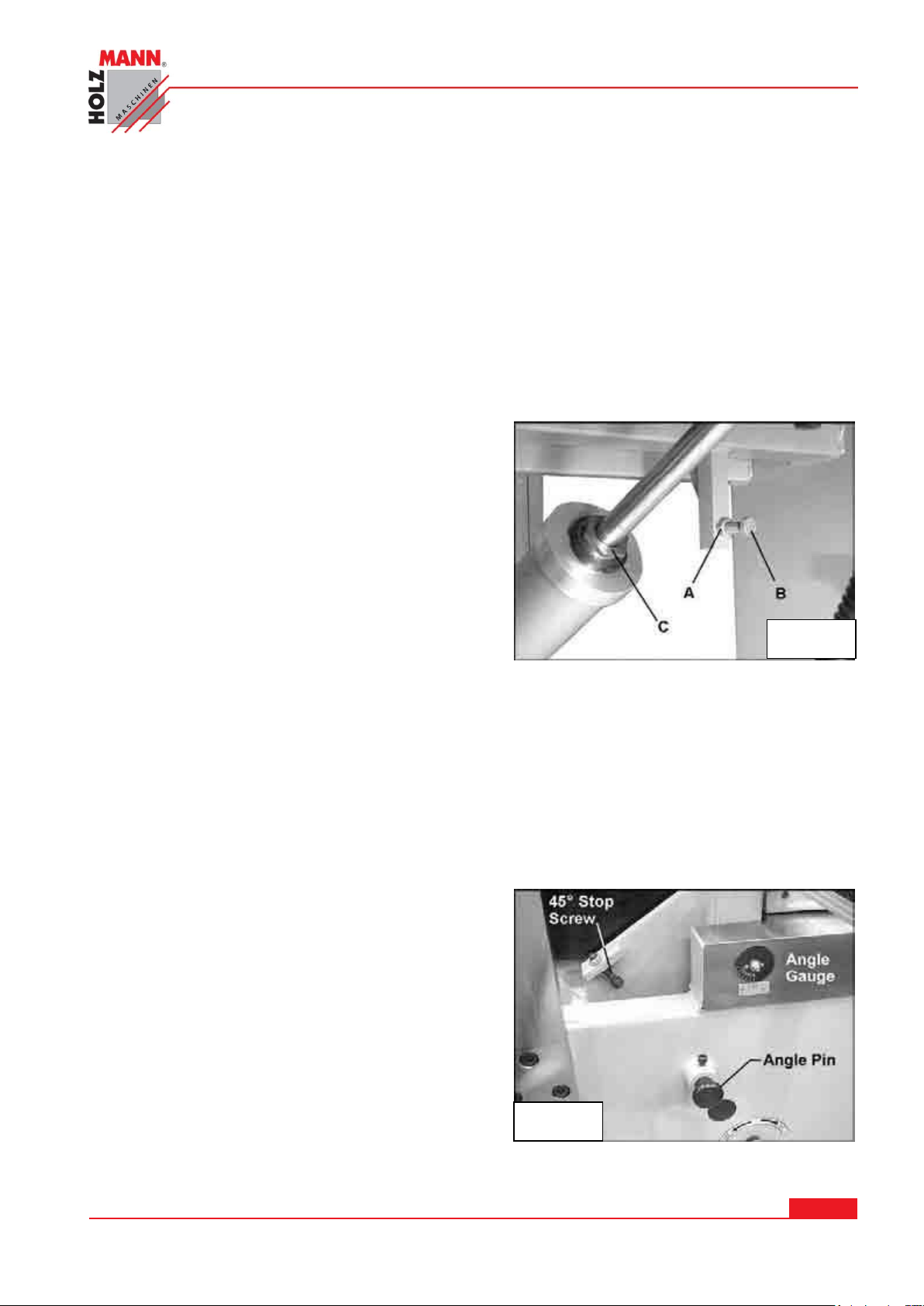
Loosen the hex nut (A, Fig. 11)
Rotate the stop screw as needed, until the boring
head will attain 90 degrees when the boring head
contacts the stop screw.
Tighten the hex nut A
13.5.7 Horizontal Stop
The horizontal stop for the boring head is
controlled by the nut located on the cylinder (C,
Fig. 11). The nut regulates how far the cylinder
rod can protrude, and thus controls where the boring head comes to a stop when pivoted to
horizontal position.
Rotate the nut as needed until the boring head is level (0 degrees) at horizontal position.
13.5.8 45 Degree Stop
The 45 degree stop for the boring head has been factory set and should require no adjustment.
As the machine receives extensive use, however, you may wish to check this setting and if
necessary adjust as follows:
The angle pin ( Fig. 12) should be pushed in
completely. (You may have to slightly loosen the
socket head cap screw on the angle pin to allow the
angle pin to move)
Loosen the hex nut on the 45 degree stop screw
(Fig. 12)
Turn the stop screw until the 45 degree angle is
obtained. Check this setting by pivoting the head
down until the stop screw contacts the angle pin.
The angle can be read on the angle gauge (Fig.
12)
Make further turns of the stop screw if needed, then tighten the hex nut on the stop screw.
When using the 45 degree stop, always tighten the locking handle (Fig. 12)
HOLZMANN MASCHINEN GmbH www.holzmann-maschinen.at Strana 34
KOLÍKOVAČKA / SINGLE-RAW MULTI-BORING MACHINE DBM 21N
Page 35
13.5.9 Clamp Position and Pressure
Fig. 13
Fig. 14
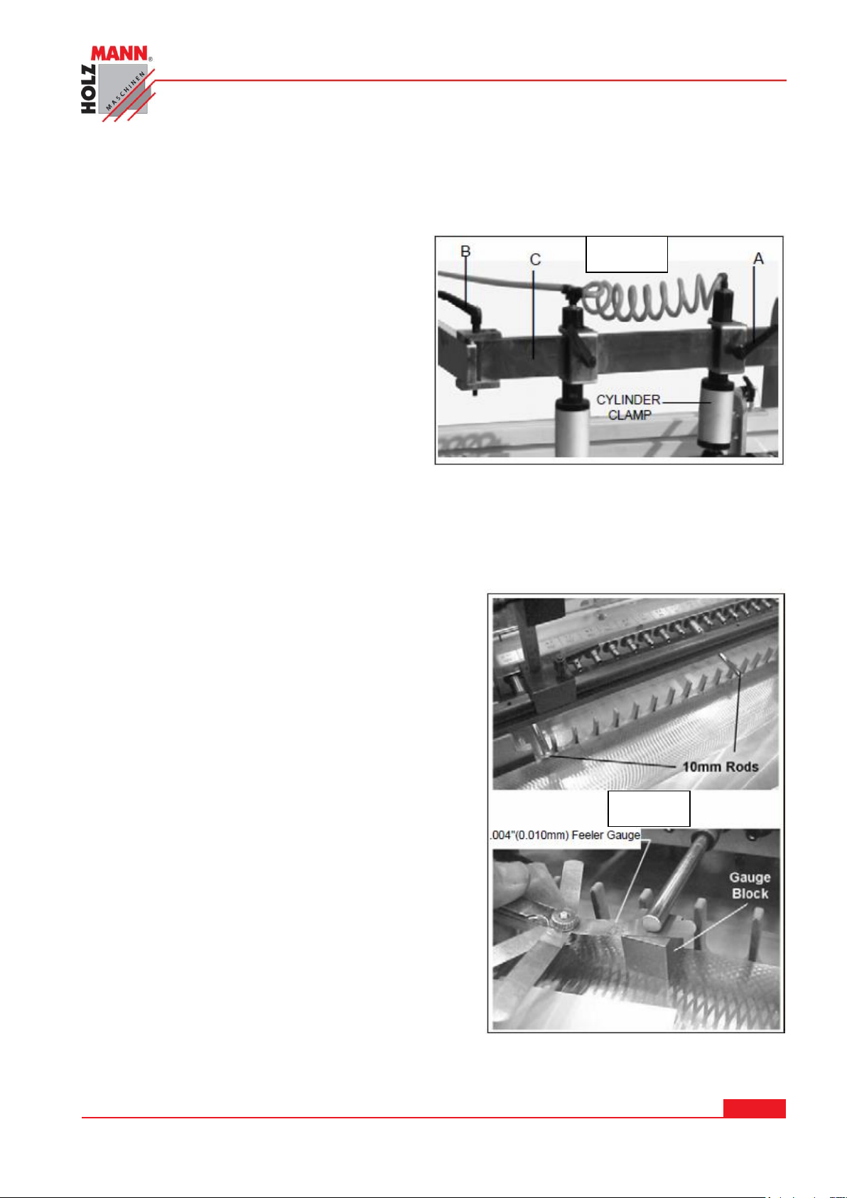
The workpiece is held to the table surface during operations by an air cylinder clamping system.
This system has multiple adjustments:
Horizontal Adjustment: Loosen the locking
handles (A, Fig. 13) and slide the clamps to
any point along the beam (C, Fig. 13). Once
the clamps are properly positioned, securely
tighten the locking handles (A, Fig. 13)
Vertical Adjustment: The clamps can be
adjusted veritcally to suit the thickness of your
workpiece. Loosen the locking handle (A, Fig.
13) and slide the clamp up or down as
desired. Re-tighten locking handle.
Parallel Adjustment: The beam (C, Fig. 13)
can be shifted to keep the clamping system in
line with the workpiece; for example, when using narrow workpieces. Loosen both locking handles
(B, Fig, 13) and slide the beam backward or forward as needed. When finished, always re-tighten
the locking handles (B, Fig. 13)
13.5.10 Parallelism of Boring Head to Table Surface
To ensure accurate hole centerlines in your
workpiece, the line of spindless must be parallel to
the table top. Check this setting and adjust if
necesarry:
Remove fence and clamp assemblies. Remove
boring bits and chucks from the spindles.
Pivot the boring head to horizontal position, and
lock it in position.
Rotate the crank handle to bring the spindles up as
far as they will go.
Insert two 10mm rods approximately 115mm long
into two quick release chucks. Mount one rod and
chuck to the center spindle, and the other rod and
chuck to the far left spindle. See Fig. 14
NOTE: The 10mm rods must be used to ensure
accuracy in the measurements.
Place a gauge block on the table and below the rod
of the center spindle, as shown in Fig. 14 (The
gauge block can be any size as long as it fits
between table and rod.)
HOLZMANN MASCHINEN GmbH www.holzmann-maschinen.at Strana 35
KOLÍKOVAČKA / SINGLE-RAW MULTI-BORING MACHINE DBM 21N
Page 36
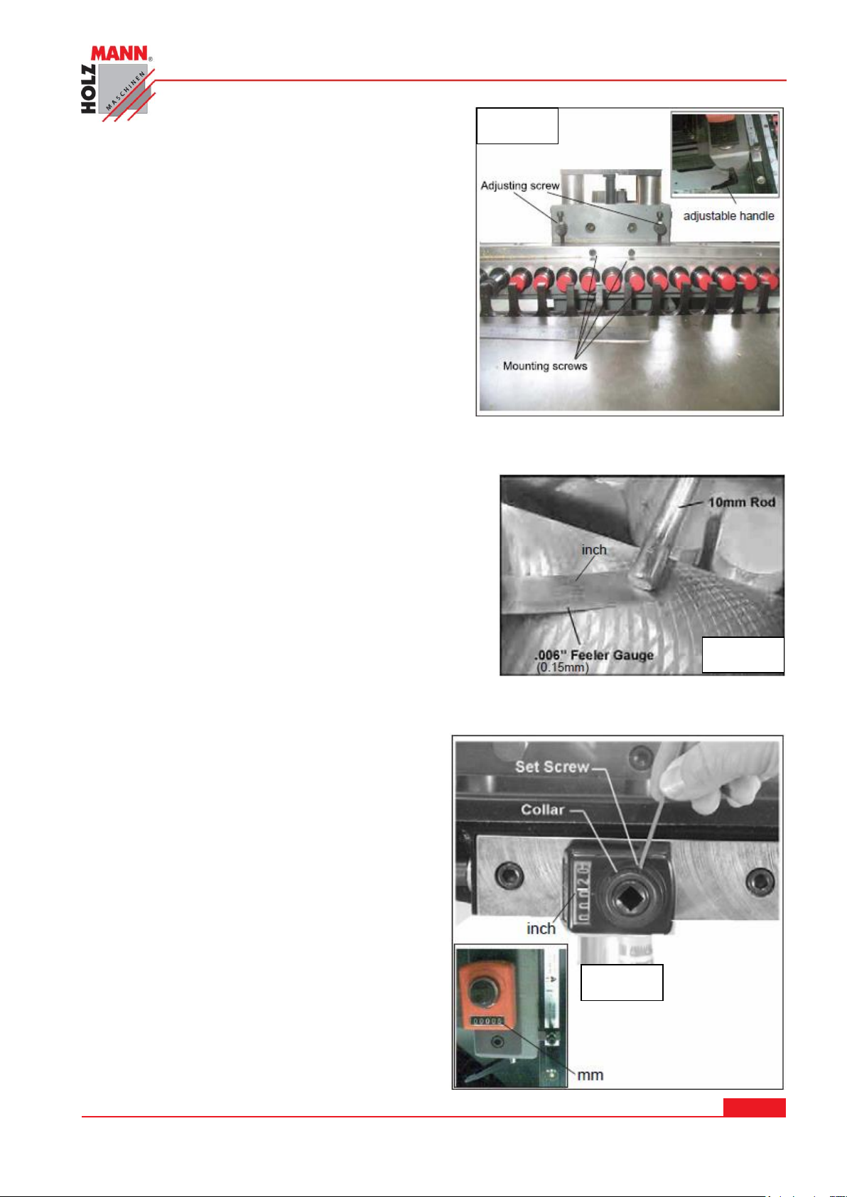
Rest a 0,01mm feeler gauge on top of gauge
Fig. 15
Fig. 17
Fig. 16
block, and lower the spindles by turning the crank
handle until the rod contacts the feeler gauge, as
shown in Fig. 14. The feeler gauge should just
rub against both the gauge block nad the rod.
Lock the boring head in this position, by
tightening the adjustable handle next to crank
handle (see Fig. 15)
Remove the chuck, with its rod, from the center
spindle and install it on the far right spindle.
Use the gauge block and feeler gauge to check
the height of the end spindles, in the same
manner as you did the center spindle. Both end spindles should match the height of the center
spindle. If they do not, loosen the four mounting screws as shown in Fig. 15. Turn two
adjustment screws (Fig. 15) slightly until the spindle heights match.
When the spindle heigths match, re-tighten the four
mounting screws.
Leave the 10mm rods on the spindles for further
adjustment procedures.
13.5.11 “Zero” the Digital Readout
This Procedure will set the digital readout so that
it reads zero when the centerline of the spindles is
aligned with the table surface.
NOTE: It is important to use 10mm rods in the
chucks and a 0,15mm feeler gauge when doing
this adjustment, as these measurements are
critical for accurate set up.
With the boring head still in horizontal position,
and the 10mm rods still in place on the spindles,
lower the spindles with the crank handle until a
0,15mm gauge just rubs between the rod and the
table surface, as shown in Fig. 17
At this point 5mm is the distance from the center
of the spindle (or rod) to the table surface.
Therefore, the mechanical digital readout should
read 5mm.
HOLZMANN MASCHINEN GmbH www.holzmann-maschinen.at Strana 36
KOLÍKOVAČKA / SINGLE-RAW MULTI-BORING MACHINE DBM 21N
Page 37
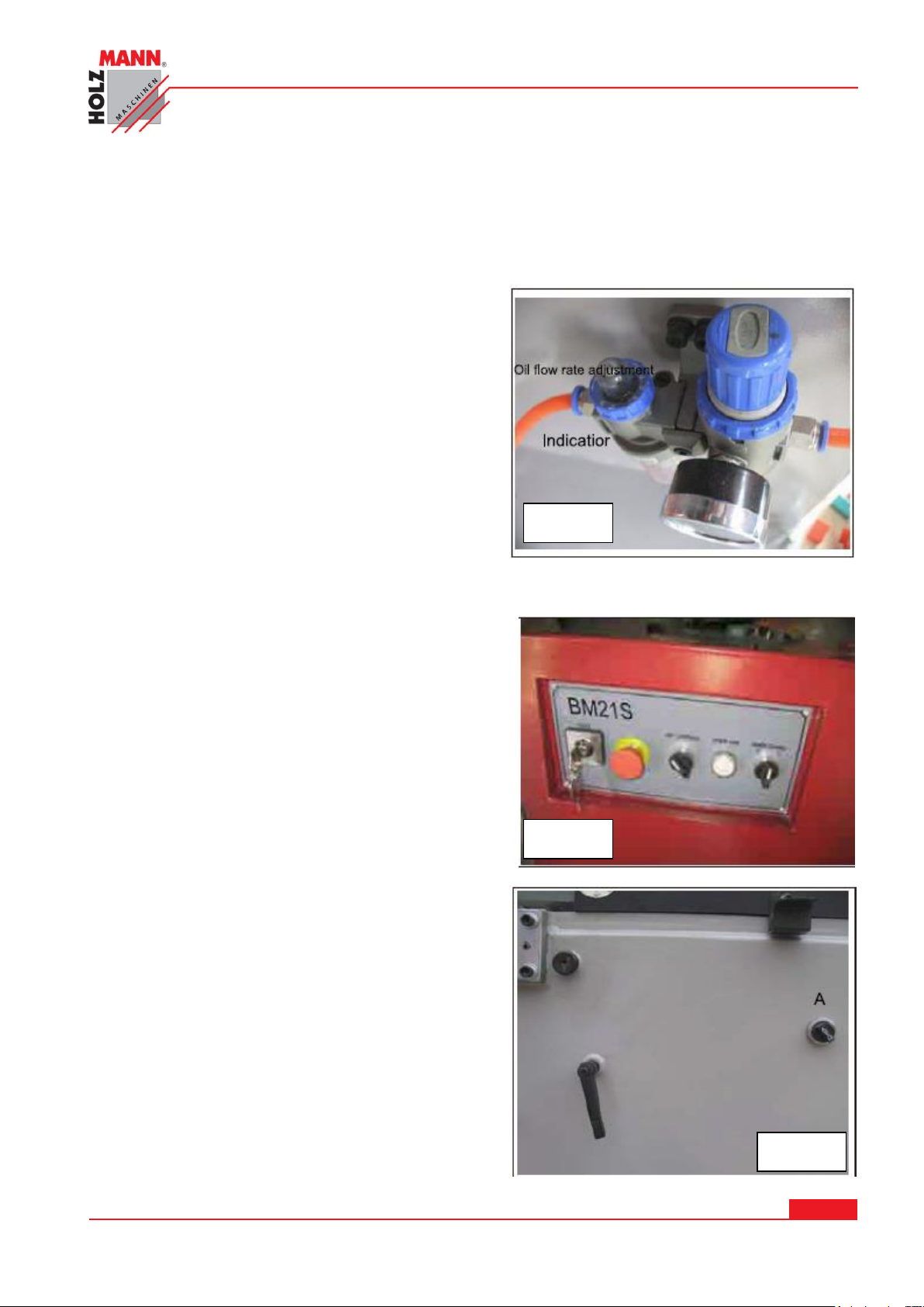
Fig. 17
Fig. 20
Fig. 19
It the readout does not indicate 5mm, lock the boring head by tightening the two lock handles.
Loosen the screw (Fig. 1) with a 2,5mm hex wrench. Rotate the collar until the display reads 5mm.
Re-tighten the set screw.
The digital readout has now been “zeroed” correctly in relation to the table surface.
Oil Flow Rate
To adjust the rate of the oil flow, rotate the oil flow
rate adjustment collar (Fig. 17) until the desired
number on the collar lines up with the small triangle
indicator on the housing adjacent to the collar. The
larger the number, the greater the rate of oil flow.
14 OPERATION
Operating Controls
The controls at the front of the machine are shown in
Fig. 19, and are described from left to right.
Vertical/Horizontal - Moves the boring head unit to
either vertical or horizontal boring positon. Fig. 20 A
Power Source - Main on/off switch
Power Lamp. - Lights up when the machine is on.
Motor - Starts and stops boring bit rotation.
Emergency Stop
This red mushroom-shaped button (Fig19) is used
for instant shut-down of the machine in case of
emergencies. After pushing it in, to restart rotate the
knurled it in, to restart the machine rotate the
knurled ring clockwise and allow the stop button to
pop back out.
A foot pedal is provided with this machine. Pressing
the foot pedal activates the hydraulic clamps and
brings the boring bits down into the workpiece.
Releasing the foot pedal releases the clamps and
retracts the boring head after the boring cycle is
completed.
HOLZMANN MASCHINEN GmbH www.holzmann-maschinen.at Strana 37
KOLÍKOVAČKA / SINGLE-RAW MULTI-BORING MACHINE DBM 21N
Page 38
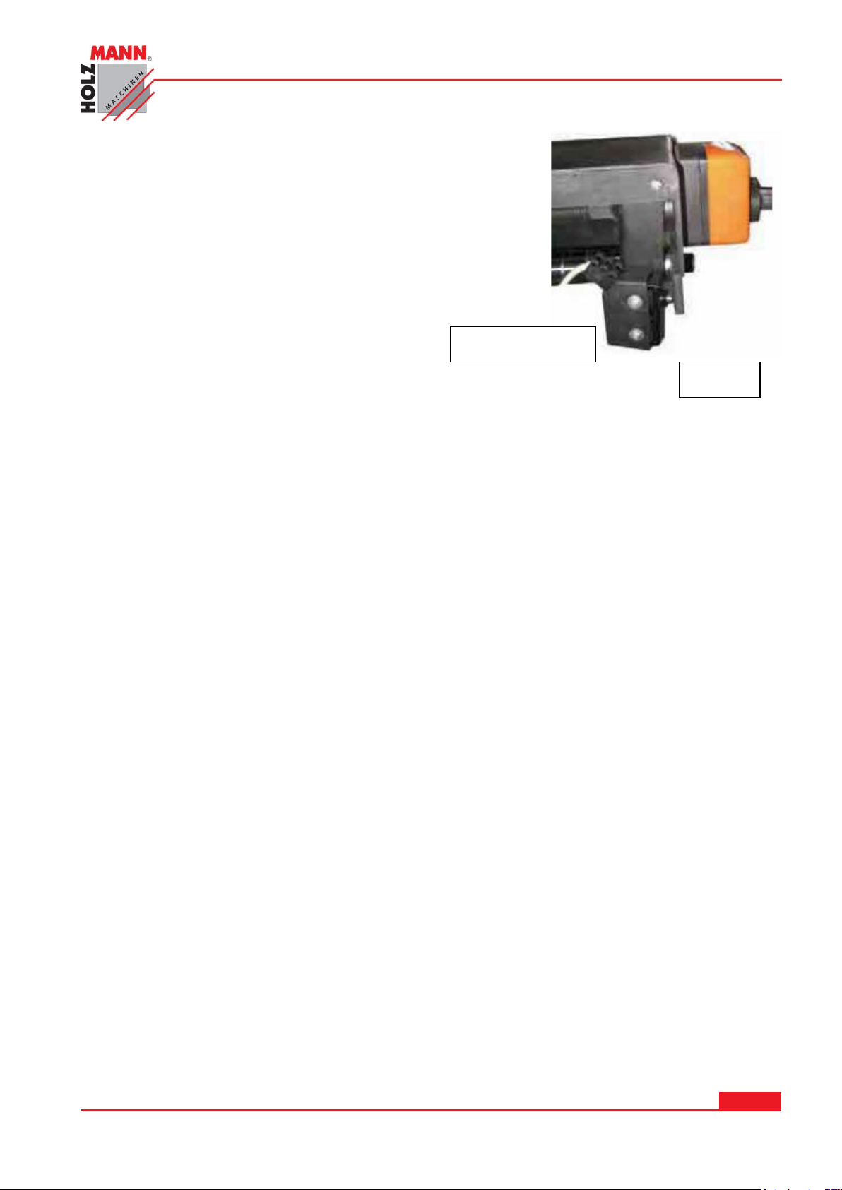
14.1.1 Limit Switch
Fig. 21
Limit switch
A limit switch is mounted below the boring head (Fig. 21). As the
boring head retracts after a boring operation, it will contract the
limit switch, which will shut off the machine, in preparation for
the next cycle.
14.2 Operation
All conversion work if power is off !!!
WARNING
This.line boring machine is for use with wood or plastic products only – Do NOT use it for
drilling in metal.
The boring bits rotate in opposite directions to prevent excessive torque against the workpiece. The
rotation of the boring bits should match the arrow indicators on the label affixed to the boring
head. This label is shown in Fig. 5.
The following is the basic procedure for operating the DBM 21N Machine.
1. Make sure all boring bits and chucks are seated on the spindles, and that boring bits are
aligned properly.
2. Turn on the power and the air supply.
3. Loosen the boring head locking handle, and position the boring head in either horizontal or
vertical position the boring head in either horizontal or vertical position. Re-tighten the
locking handle.
4. Rotate the turret depth selector to the desired boring depth.
5. Adjust side fences. Set fence stops as neccesary.
6. Adjust clamping system for the size of your workpiece.
7. Rotate the crank handle to establish the centerline of your holes.
8. Place the workpiece in positon against the fence and stops. Press the foot pedal to advance
the boring head and perform the boring procedure. NOTE: The bits will remain rotating in the
workpiece as long as the foot pedal is held down.
9. Release the foot pedal, and allow the boring head to clear the workpiece. The machine will
shut off automatically.
10. Remove workpiece from the table
HOLZMANN MASCHINEN GmbH www.holzmann-maschinen.at Strana 38
KOLÍKOVAČKA / SINGLE-RAW MULTI-BORING MACHINE DBM 21N
Page 39
15 MAINTENANCE
ATTENTION
Don’t clean or do maintenance on the machine while it is still connected to the
power supply:
Damages to machine and injuries might occur due to unintended switching on of
the machine!
Therefore: Switch the machine off and disconnect it from the power supply before any maintenance works or cleaning is carried out
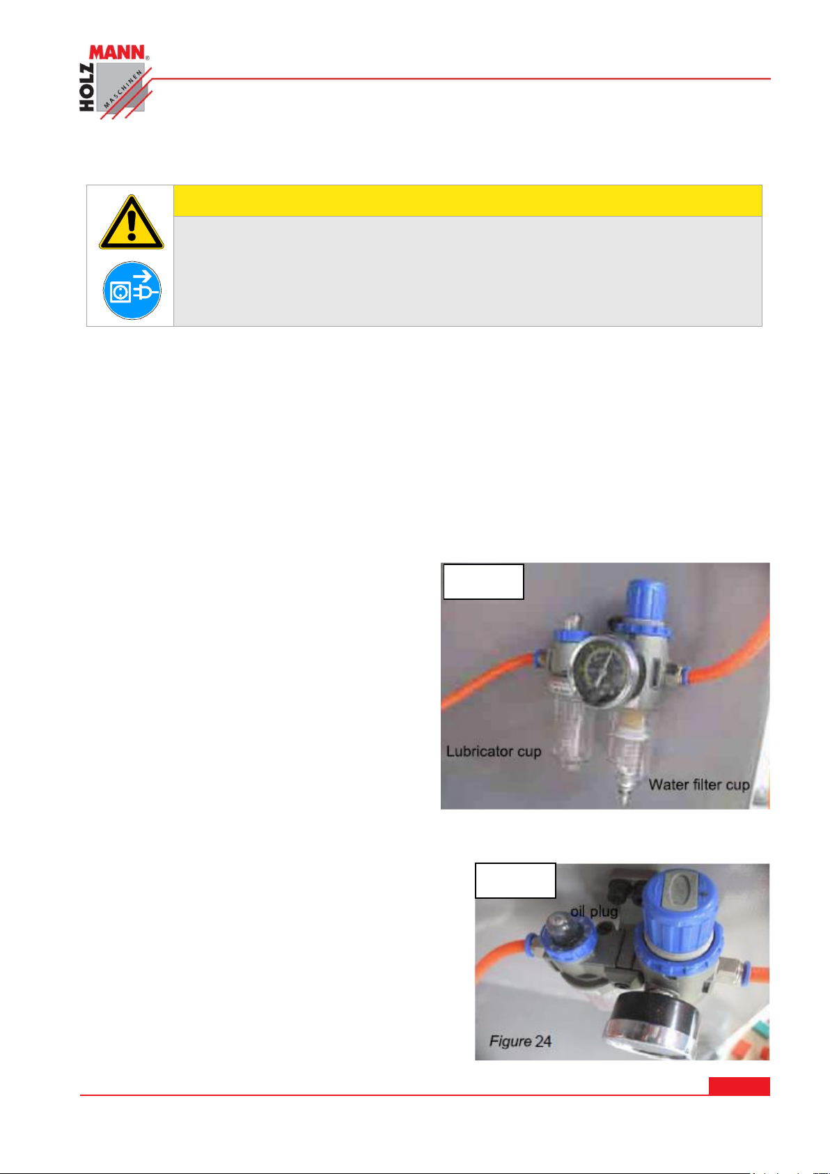
Fig. 22
Fig. 23
The machine does not require extensive maintenance. If malfunctions and defects occur, let it be
serviced by trained persons only.
Before first operation as well as later on every 100 operation hours you should lubricate all connecting parts (if required, remove beforehand with a brush all swarfs and dust).
Check regularly the condition of the security stickers. Replace them if required.
Check regularly the condition of the saw band and the saw band guide.
The good condition and perfect adjustment of the guiding rollers is essential for a smooth band
guidance and a clean cut.
Store the machine in a closed, dry location.
Always keep oil in the lubricator cup (Fig. 23) to
at least 80 percent of full cup capacity.
Unscrew and remove the oil plug (Fig. 24) with a
flat head screwdriver, and add oil through the
inlet port. Use standard air tool oil. Always reinstall the oil plug after adding oil.
The water filter cup (Fig 24) collects moisture
from the air line. Periodically remove any water
that collects in the water filter cup by pushing up
the release valve at the bottom of the cup.
If the power cord is worn, cut, or damaged in
any way, have it replaced immediately.
The table surface must be kept clean and free of rust results.
HOLZMANN MASCHINEN GmbH www.holzmann-maschinen.at Strana 39
KOLÍKOVAČKA / SINGLE-RAW MULTI-BORING MACHINE DBM 21N
Page 40
15.1 Lubrication
NOTE
The use of solvents, harsh chemicals or abrasive cleaners leads to damage to the machine!
Therfore: When cleaning water and mild detergent if necessary use.
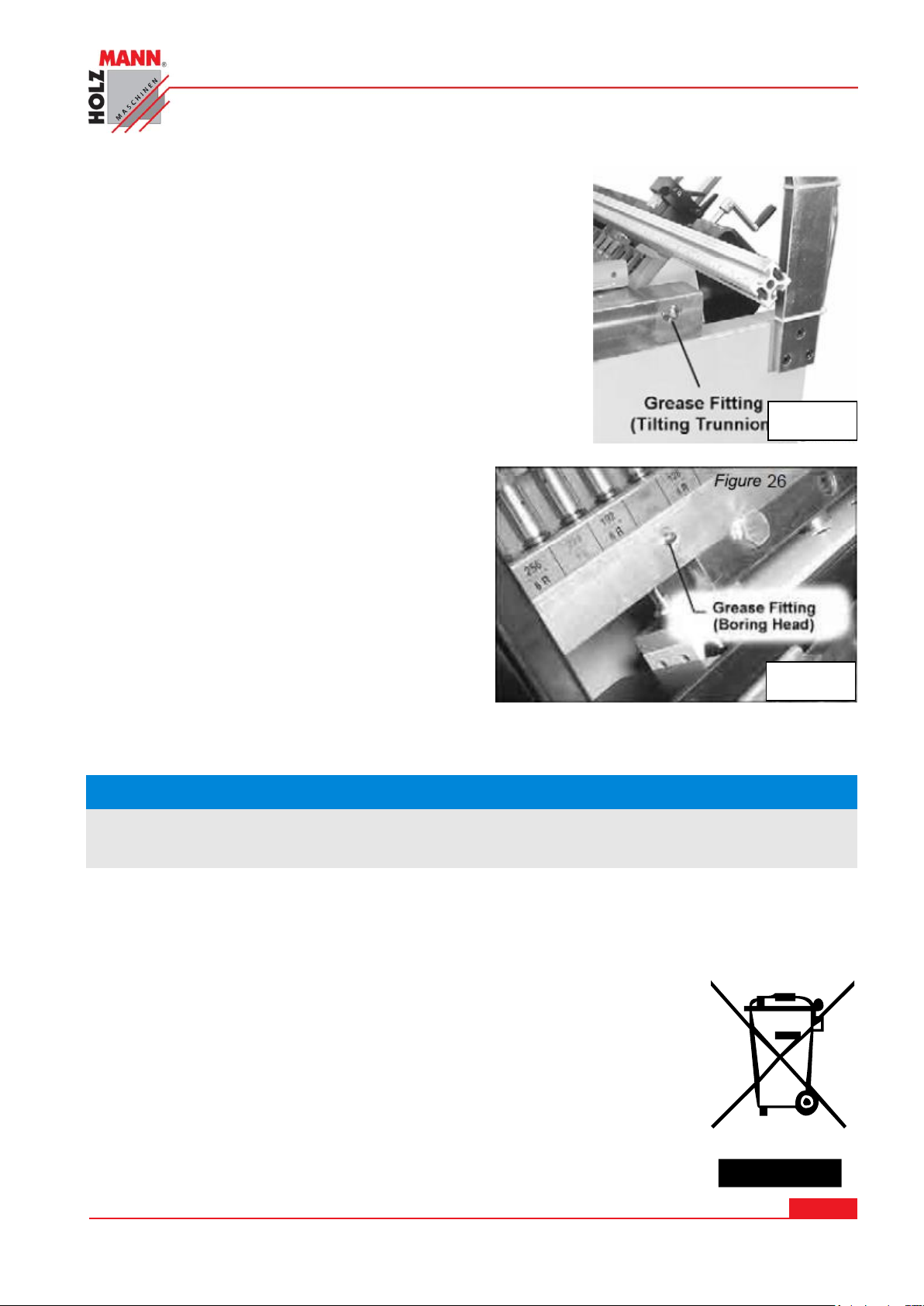
Fig. 24
Fig. 25
Occasionally wipe clean guide rods and cylinders. If there is
an appreciable build-up of dust, dirt or wood shavings.
Grease the boring head tilting trunnion through the two
grease fittings at opposite sides of the frame (Fig. 24). Use a
good quality general-purpose grease.
Grease the gears within the boring head, using the two grease
fittings at the back of the boring head (Fig 25)
15.2 Cleaning
Bare surfaces of the machine against corrosion impregnate ( with anti-rust WD40 )
15.3 Disposal
Do not dispose of the DBM 21N in residual waste. Contact your local
authorities for information regarding the available disposal options. When you
buy at your local dealer for a replacement unit, the latter is obliged to exchange
your old
HOLZMANN MASCHINEN GmbH www.holzmann-maschinen.at Strana 40
KOLÍKOVAČKA / SINGLE-RAW MULTI-BORING MACHINE DBM 21N
Page 41
16 TROUBLE SHOOTING
Trouble
Possible cause
Solution
Machine does not start
Not connected to power source
Fuse blown, or circuit breaker
tipped
Cord damaged
Check plug connection.
Replace fuse, or reset circuit
breaker
Replace cord
Drill speed is not
sufficient;
machine has low
power
Feed rate not adjusted properly
Extension cord too light or too
long
Low current
Adjust feed rate control
Replace with adequate size
and length cord
Contact a qualified electrician
After drilling, boring
head will not retract.
Adjustable air relief valve
damaged
Replace air relief valve
After drilling, the air
cylinder clamp(s) will
not rise
Adjustable air relief valve
damaged
Spring in the air cylinder clamp
is broken
Replace air relief valve
Replace clamp
Boring head will not
advance
Air hose is cracked/broken
Speed regulator valve too tight
Air leaking form air cylinder
Limit switch damged
Foot pedal not operating
Replace air hose
Loosen speed regulator valve
Repair or replace air cylinder
Replace limit switch
Replace foot pedal switch
Smoke occurs while
holes are being drilled
Wood is wet
Boring bits are dull
Air pressure insufficient
Use dry stock
Sharpen or replace boring
bits
Properly set air pressure to
approximately 90 psi
or 6 – 8 bar
Disconnect the machine from the power supply prior to any checks performed at the
machine itself !
HOLZMANN MASCHINEN GmbH www.holzmann-maschinen.at Strana 41
KOLÍKOVAČKA / SINGLE-RAW MULTI-BORING MACHINE DBM 21N
Page 42
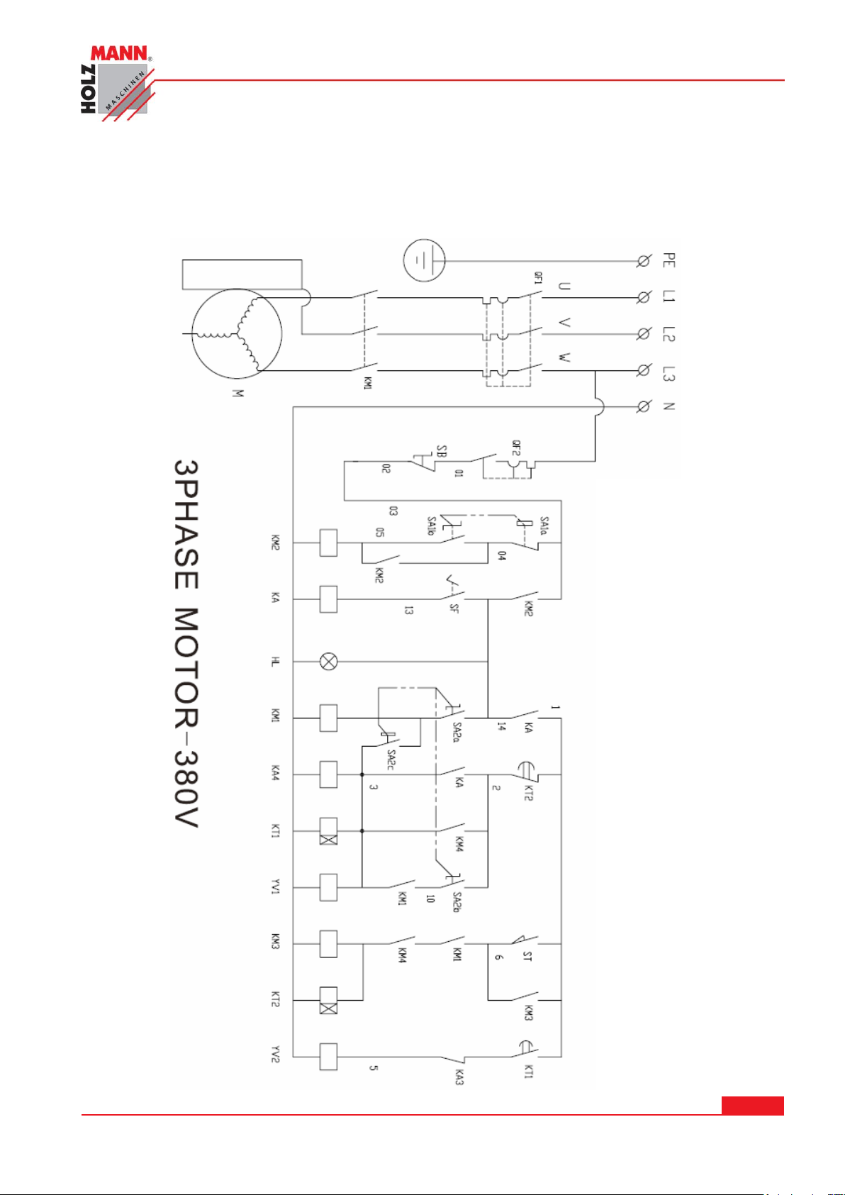
17 PLÁNY ZAPOJENÍ / DIAGRAMS
17.1 ELEKTRICKÉ ZAPOJENÍ / WIRING DIAGRAM
HOLZMANN MASCHINEN GmbH www.holzmann-maschinen.at Strana 42
KOLÍKOVAČKA / SINGLE-RAW MULTI-BORING MACHINE DBM 21N
Page 43
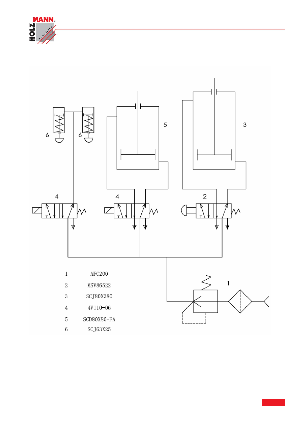
17.2 Schéma pneumatického zapojení / Pneumatic diagram
HOLZMANN MASCHINEN GmbH www.holzmann-maschinen.at Strana 43
KOLÍKOVAČKA / SINGLE-RAW MULTI-BORING MACHINE DBM 21N
Page 44
VÝSTRAHA
Použití jiných než originálních náhradních dílů má za následek ztrátu záruky!
Platí: Při výměně komponent/dílů používejte pouze originální náhradní díly
IMPORTANT
The installation of other than original spare parts voids the warranty!
So you always have to use original spare parts
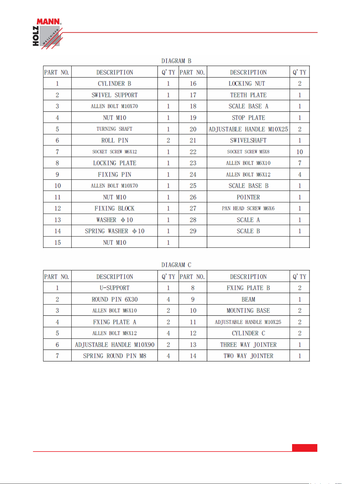
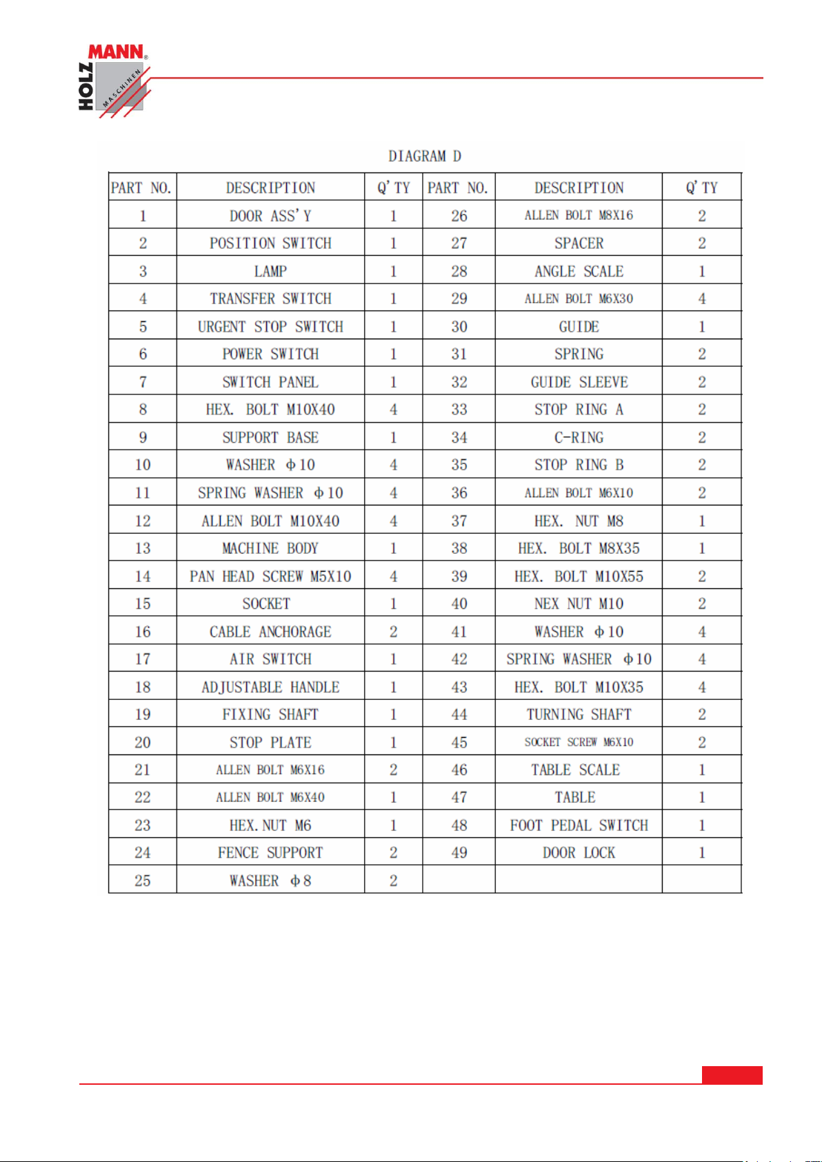
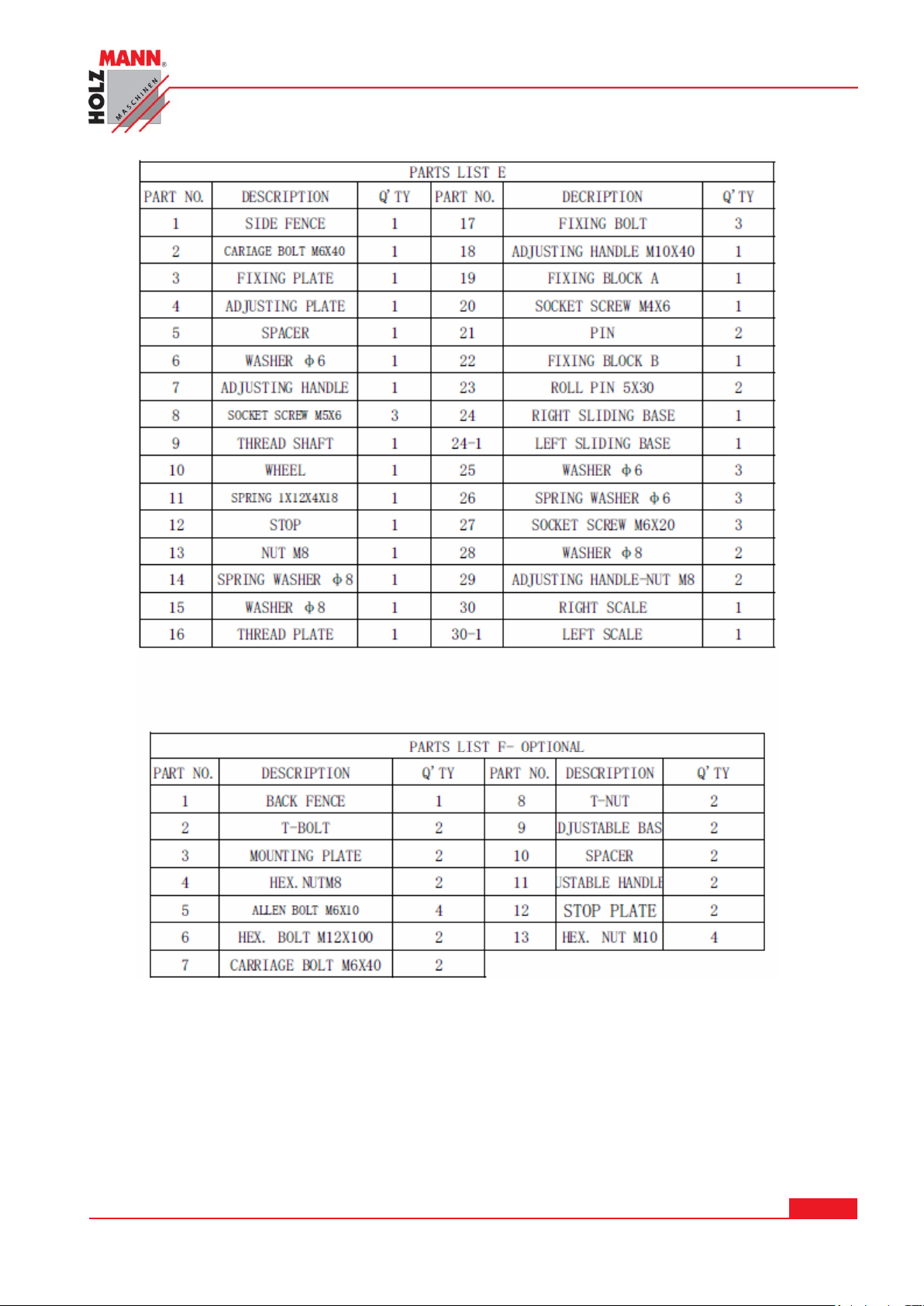
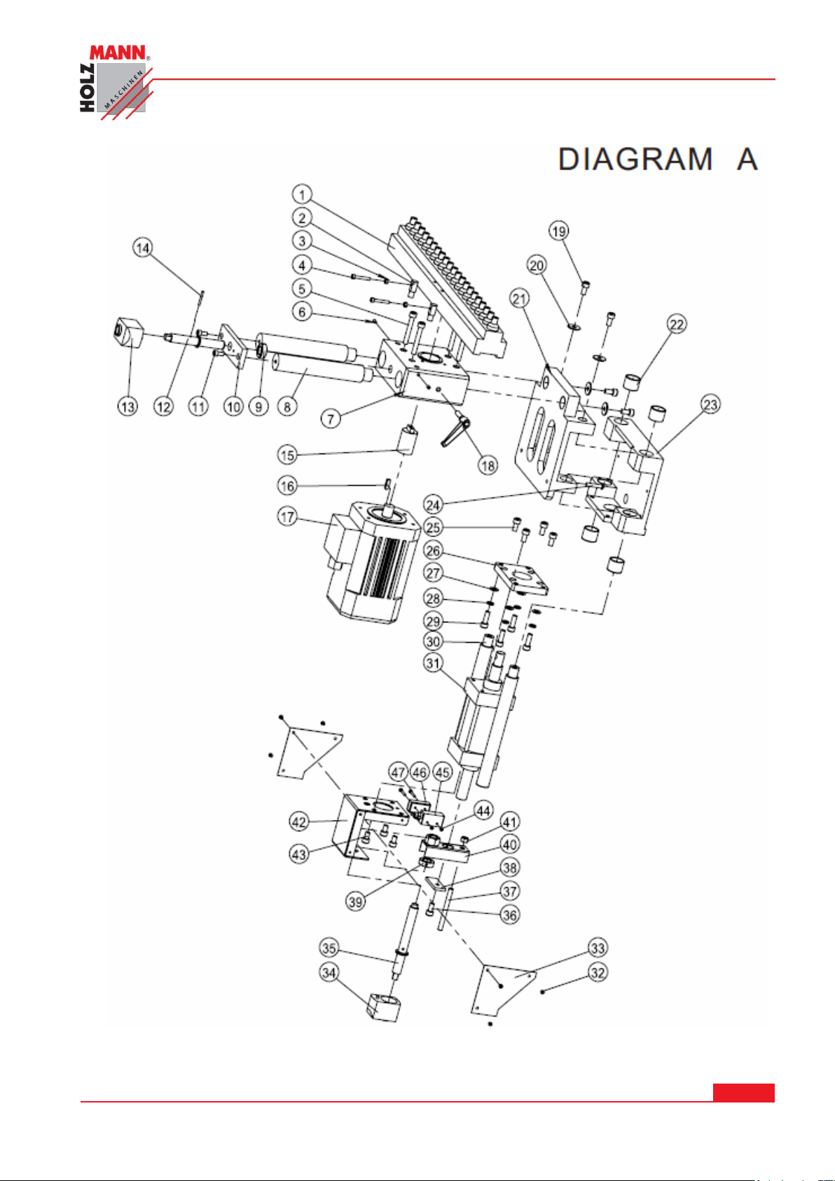
18 NÁHRADNÍ DÍLY / SPARE PARTS
18.1 Obejdnávky náhradních dílů / spare parts order
Použitím originálních dílů od společnosti HOLZMANN používáte díly, které spolu dokonale sedí a
jejich montáž je časově méně náročná. Originální náhradní díly zajišťují delší životnost stroje.
Při objednávání dílů použijte servisní formulář, který najdete na konci tohoto návodu na
obsluhu. Vždy uvádějte typ stroje, číslo náhradního dílu a jeho název. Aby se předešlo
neshodám, doporučujeme společně s objednávkou zaslat i kopii výkresu rozpadu náhradních
dílů, na kterém Vámi požadované díly označíte.
Adresu pro objednání dílů naleznete v kontaktech na zákaznický servis.
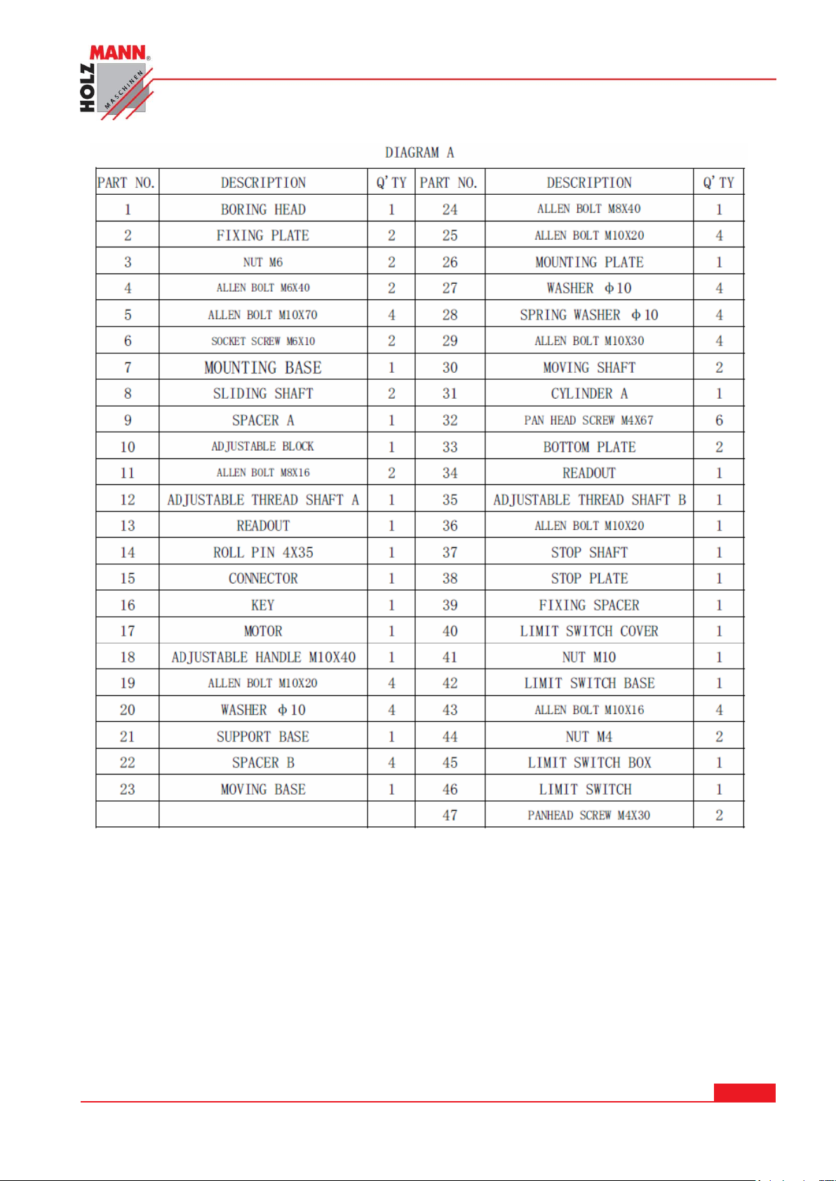
With original HOLZMANN spare parts you use parts that are attuned to each other shorten the
installation time and elongate your products lifespan.
When you place a spare parts order please use the service formular you can find in the last
chapter of this manual. Always take a note of the machine type, spare parts number and
partname. We recommend to copy the spare parts diagram and mark the spare part you need.
You find the order address in the preface of this operation manual.
HOLZMANN MASCHINEN GmbH www.holzmann-maschinen.at Strana 44
KOLÍKOVAČKA / SINGLE-RAW MULTI-BORING MACHINE DBM 21N
Page 45
HOLZMANN MASCHINEN GmbH www.holzmann-maschinen.at Strana 45
KOLÍKOVAČKA / SINGLE-RAW MULTI-BORING MACHINE DBM 21N
Page 46
HOLZMANN MASCHINEN GmbH www.holzmann-maschinen.at Strana 46
KOLÍKOVAČKA / SINGLE-RAW MULTI-BORING MACHINE DBM 21N
Page 47
HOLZMANN MASCHINEN GmbH www.holzmann-maschinen.at Strana 47
KOLÍKOVAČKA / SINGLE-RAW MULTI-BORING MACHINE DBM 21N
Page 48
HOLZMANN MASCHINEN GmbH www.holzmann-maschinen.at Strana 48
KOLÍKOVAČKA / SINGLE-RAW MULTI-BORING MACHINE DBM 21N
Page 49
HOLZMANN MASCHINEN GmbH www.holzmann-maschinen.at Strana 49
KOLÍKOVAČKA / SINGLE-RAW MULTI-BORING MACHINE DBM 21N
Page 50
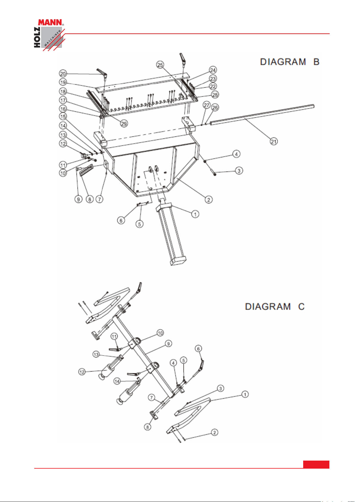
HOLZMANN MASCHINEN GmbH www.holzmann-maschinen.at Strana 50
KOLÍKOVAČKA / SINGLE-RAW MULTI-BORING MACHINE DBM 21N
Page 51
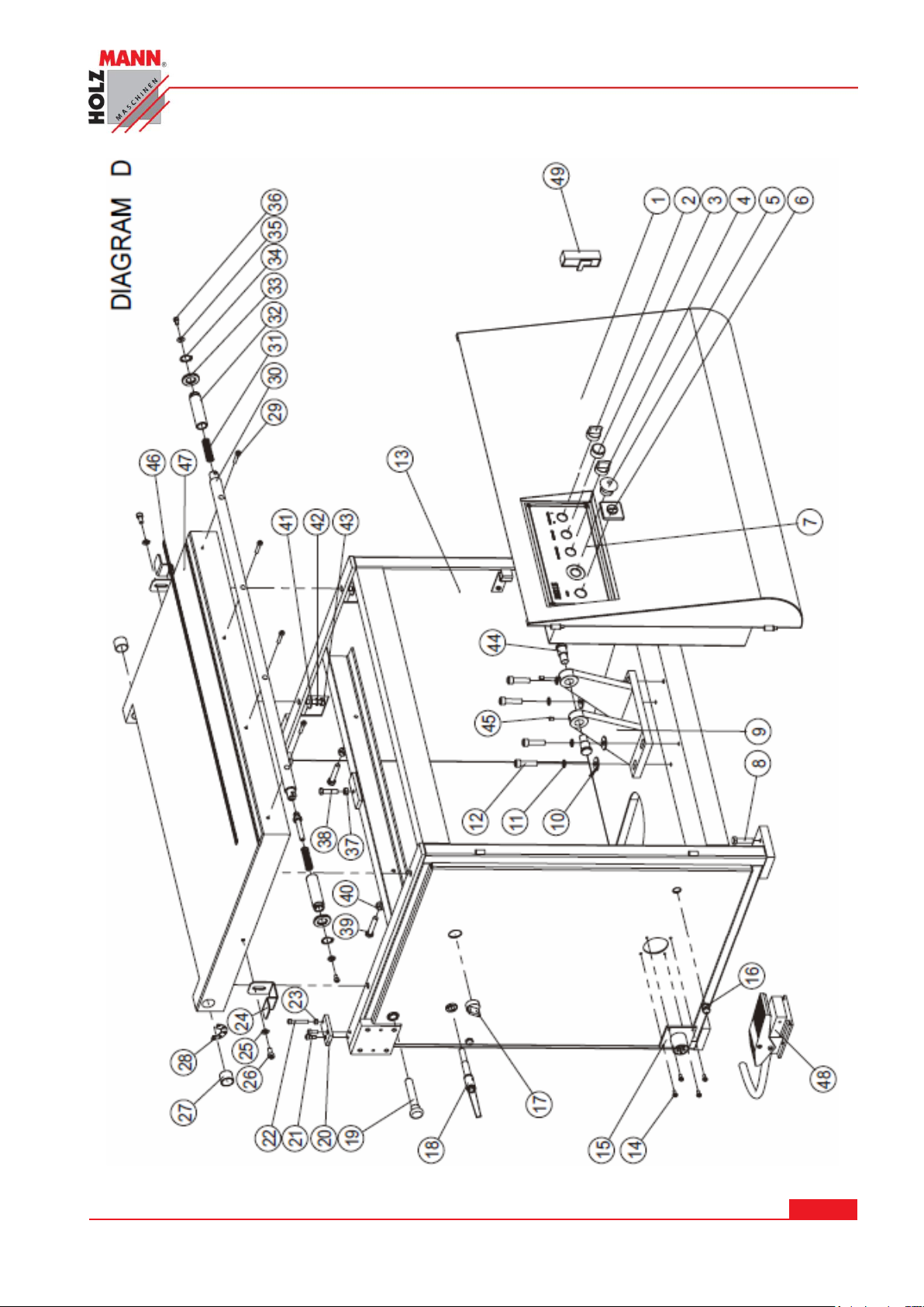
HOLZMANN MASCHINEN GmbH www.holzmann-maschinen.at Strana 51
KOLÍKOVAČKA / SINGLE-RAW MULTI-BORING MACHINE DBM 21N
Page 52
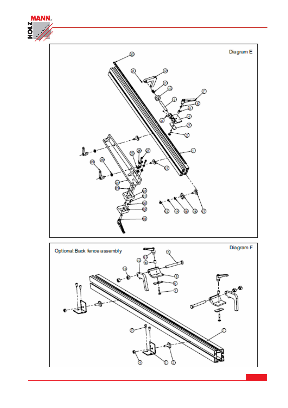
HOLZMANN MASCHINEN GmbH www.holzmann-maschinen.at Strana 52
KOLÍKOVAČKA / SINGLE-RAW MULTI-BORING MACHINE DBM 21N
Page 53
19 PROHLÁŠENÍ O SHODĚ / CERTIFICATE OF CONFORMITY
D o v o z c e / D i s t r i b u t o r
HOLZMANN MASCHINEN®
A-4170 Haslach, Marktplatz 4
Tel.: +43 7289 71562-0; Fax.: +43 7289 71562-4
Název / name
Kolíkovačka / single-raw multi-boring machine
Typ / model
DBM 21N
Směrnice ES / EC-directives
2006/42/ES
2006/95/ES
Použité normy / applicable Standards
EN 60204-1:2006+A1
Haslach, 24.06.2014
Místo/Datum place/date
Klaus Schörgenhuber
Jednatel / Director
Tímto prohlašujeme, že výše uvedený typ stroje splňuje bezpečnostní a zdravotní požadavky směrnic ES.
Toto prohlášení ztrácí svou platnost, pokud by došlo ke změnám nebo úpravám stroje, které námi nebyly
odsouhlaseny
Hereby we declare that the above mentioned machines meet the essential safety and health requirements of
the above stated EC directives. Any manipulation or change of the machine not being explicitly authorized by
us in advance renders this document null and void.
__________________________
Gerhard Brunner
Technická Dokumentace
Technical documentation
HOLZMANN MASCHINEN GmbH www.holzmann-maschinen.at Strana 53
KOLÍKOVAČKA / SINGLE-RAW MULTI-BORING MACHINE DBM 21N
Page 54

20 ZÁRUČNÍ PODMÍNKY
(Stav k 24.06.2014)
Záruční požadavky kupujícího vyplývající z kupní smlouvy a uplatněné u prodejce (obchodní zastoupení
firmy Holzmann) stejně jako práva vyplývající z legislativy příslušné země zůstávají tímto prohlášením
nedotčeny.
Pro tento stroj platí následující záruční podmínky:
A) Záruka zahrnuje bezplatné odstranění veškerých vad stroje, za předpokladu splnění podmínek dle bodů
(B-G), které omezují správnou funkci stroje a jsou způsobeny vadou materiálu nebo výrobní vadou.
B) Záruční doba je 12 měsíců, u komerčního použití 6 měsíců od dodání zboží prvnímu kupujícímu.
K reklamaci předložte originální doklad o dodání zboží a kupní doklad v případě vlastního odběru zboží.
C) Pro nahlášení reklamace kontaktujte obchodní zastoupení společnosti HOLZMANN, u kterého jste
výrobek pořídili a předložte následující doklady:
Kupní doklad/nebo doklad o dodávce zboží
Vyplněný Servisní formulář s hlášením vady
Při požadavku na dodání náhradního dílu kopii výkresu náhradních dílů s vyznačením potřebného dílu.
Průběh řešení reklamace a místo plnění určuje společnost HOLZMANN GmbH.
D)
Snadno odstranitelné vady budou odstraněny obchodním zastoupením, u rozsáhlejších vad si
vyhrazujeme parvo na odborné posouzení na adrese sídla firmy č. 4170 Haslach, Österreich. Pokud není
v servisní smlouvě explicitně uvedeno jinak, platí, že místem pro vyřízení reklamace je sídlo společnosti
HOLZMANN-MASCHINEN na adrese 4170 Haslach, Österreich. Tato záruka výrobce nekryje případné
náklady na přepravu zboží do sídla firmy
E) Výluky ze záruky:
Na díly, které vykazují známky opotřebení a při vadách stroje, které jsou následkem běžného
opotřebení.
Při nevhodné nebo nedbalé montáži stroje, chybného uvedení do provozu příp. nevhodného připojení
k elektrické síti.
Při nedodržení pokynů pro obsluhu stroje, nevhodném použití, nestandardních podmínkách
prostředí, nevhodných podmínkách pro provoz, nedostatečné údržbě a péči o stroj atd.
Při použití a/nebo zamontování neoriginálních dílů a příslušenství nebo při dodatečných úpravách,
které nejsou schváleny společností HOZMANN.
U zanedbatelných odchylek výrobku od jeho popisu, přičemž tyto nemají vliv na hodnotu nebo
použití stroje pro dané účely.
Při překročení zátěže stroje. Zejména při vadách způsobených přetížením stroje z důvodu jeho
vytížení pro komerční účely, pro které tento stroj nebyl zkonstruován
F) V rámci této záruky jsou další nároky kupujícího nad rámec plnění uvedeného v tomto dokumentu
vyloučeny.
Tyto záruční podmínky přijímá kupující ze svobodné vůle. Tato záruka vylučuje případné prodloužení
G)
záruční doby, a to i na náhradní díly
SERVIS
Po uplynutí záruční doby mohou být opravy realizovány i u neautorizovaných servisních firem.
K dispozici je Vám samozřejmě i nadále servis společnosti HOLZMANN-Maschinen GmbH.
V takovém případě uplatněte Vaše nezávazné poptávky/reklamace s údaji dle bodu C) na náš zákaznický
servis nebo nám pošlete vyplněný přiložený servisní formulář.
Mail: [email protected]
FAX: +43 7289 71562 0
.
.
.
HOLZMANN MASCHINEN GmbH www.holzmann-maschinen.at Strana 54
KOLÍKOVAČKA / SINGLE-RAW MULTI-BORING MACHINE DBM 21N
Page 55

21 GUARANTEE TERMS
(applicable from 24.06.2014)
Please consult our troubleshooting section for initial problem solving. Feel free to contact your HOLZMANN reseller or us
for Customer Support!
Warranty claims based on your sales contract with your HOLZMANN retailer, including your statutory rights, shall not be
affected by this guarantee declaration. HOLZMANN-MASCHINEN grants guarantee according to following conditions:
A) The guarantee covers the correction of deficiencies to the tool/product, at no charge, if it can be verified adequately
that the deficiencies were caused by a material or manufacturing fault.
B) The guarantee period lasts 12 months, and is reduced to 6 months for tools in commercial use. The guarantee period
begins from the time the new tool is purchased from the first end user. The starting date is the date on the original
delivery receipt, or the sales receipt in the case of pickup by the customer.
C) Please lodge your guarantee claims to your HOLZMANN reseller you acquired the claimed tool from with following
information:
>> Original Sales receipt and/or delivery receipt
>> Service form (see next page) filed, with a sufficient deficiency report
>> for spare part claims: a copy of the respective exploded drawing with the required spare parts being marked
clear and unmistakable.
D) The Guarantee handling procedure and place of fulfillment is determined according to HOLZMANNs sole discretion in
accordance with the HOLZMANN retail partner. If there is no additional Service contract made including on-site
service, the place of fulfillment is principally the HOLZMANN Service Center in Haslach, Austria.
E) Transport charges for sending to and from our Service Center are not covered in this guarantee.
F) The Guarantee does not cover:
- Wear and tear parts like belts, provided tools etc., except to initial damage which has to be claimed immediately
after receipt and initial check of the product.
- Defects in the tool caused by non-compliance with the operating instructions, improper assembly, insufficient power
supply, improper use, abnormal environmental conditions, inappropriate operating conditions, overload or insufficient
servicing or maintenance.
- Damages being the causal effect of performed manipulations, changes, additions made to the product.
- Defects caused by using accessories, components or spare parts other than original HOLZMANN spare parts.
- Slight deviations from the specified quality or slight appearance changes that do not affect functionality or value of
the tool.
- Defects resulting from a commercial use of tools that - based on their construction and power output - are not
designed and built to be used within the frame of industrial/commercial continuous load.
G) Claims other than the right to correction of faults in the tool named in these guarantee conditions are not covered by
our guarantee.
H) This guarantee is voluntary. Therefore Services provided under guarantee do not lengthen or renew the guarantee
period for the tool or the replaced part.
SERVICE
After Guarantee and warranty expiration specialist repair shops can perform maintenance and repair jobs. But we are still
at your service as well with spare parts and/or product service. Place your spare part / repair service cost inquiry by filing
the SERVICE form on the following page and send it:
via Mail to [email protected]
or via Fax to: +43 7289 71562 4
HOLZMANN MASCHINEN GmbH www.holzmann-maschinen.at Strana 55
KOLÍKOVAČKA / SINGLE-RAW MULTI-BORING MACHINE DBM 21N
Page 56
J m é n o / n a m e :
V ý r o b e k / p r o d u c t :
D a t u m n á k u p u / p u r c h a s e d a t e :
Z a k o u p e n o v / p u r c h a s e d f r o m :
E - M a i l / e - m a i l :
Děkujeme za Vaši spolupráci! / Thank you for your kind cooperation!
KONTAKT / CONTACT:
HOLZMANN MASCHINEN
4170 Haslach, Marktplatz 4 AUSTRIA
Tel : +43 7289 71562 0
Fax: +43 7289 71562 4
[email protected]
22 SLEDOVÁNÍ VÝROBKU
PRODUCT EXPERIENCE FORM
Po dodání nás zajímá Vaše spokojenost s
výrobkem.
We observe the quality of our delivered products
in the frame of a Quality Management policy.
Při procesu zlepšování výrobků jsme totiž
závislí na Vás a Vašich zkušenostech s prací
se strojem:
Your opinion is essential for further product
development and product choice. Please let us
know about your:
- Potíže, které se vyskytly během provozu
výrobku.
- Impressions and suggestions for
improvement.
- Chybné funkce stroje, které se vyskytly
za určitých provozních podmínek.
- experiences that may be useful for other
users and for product design
- Vaše vlastní zkušenosti z provozu, které
mohou být užitečné i pro ostatní uživatele
stroje.
- Experiences with malfunctions that occur in
specific operation modes
Prosíme Vás o zaznamenání Vašich
zkušeností a zaslání na naši adresu emailem,
faxem nebo poštou:
We would like to ask you to note down your
experiences and observations and send them to
us via FAX, E-Mail or by post:
Moje zkušenosti / My experiences:
HOLZMANN MASCHINEN GmbH www.holzmann-maschinen.at Strana 56
KOLÍKOVAČKA / SINGLE-RAW MULTI-BORING MACHINE DBM 21N
Page 57
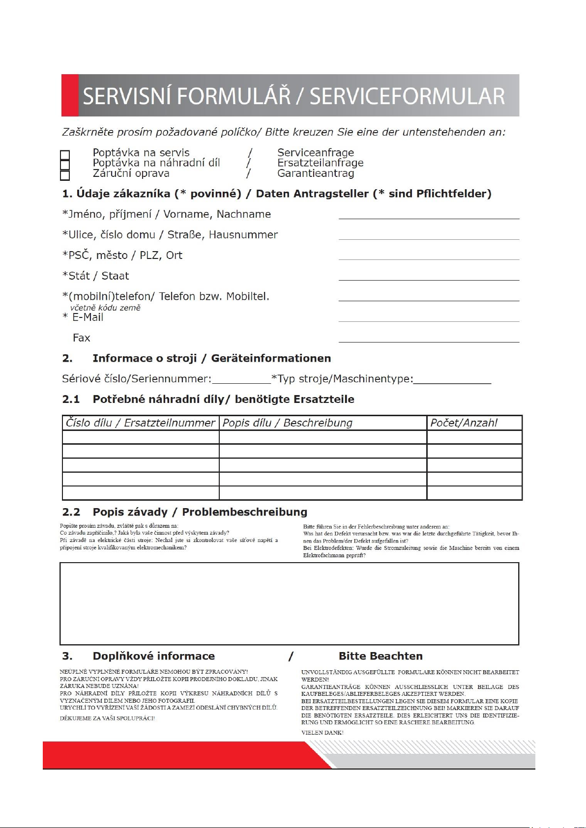
 Loading...