

Page 1
Edition: 13.09.2017 – Revision - 00 – CEC – DE/EN/IT
Originalfassung
DE
BETRIEBSANLEITUNG
METALLBANDSÄGE
Übersetzung / Translation
EN
USER MANUAL
METAL BAND SAW
IT
ISTRUZIONI PER L'USO
SEGA A NASTRO PER METALLI
BS 128HDR
BS 115
Page 2

INHALT /INDEX
1 INHALT /INDEX
2 SICHERHEITSZEICHEN / SAFETY SIGNS 6
4 VORWORT (DE) 7
5 TECHNIK 8
5.1 Komponenten ..................................................................................................................................... 8
5.1.1 BS115 ........................................................................................................................................ 8
5.1.2 BS128HDR .................................................................................................................................. 8
5.2 Technische Daten BS115..................................................................................................................... 9
5.3 Technische Daten BS128HDR .............................................................................................................. 9
6 SICHERHEIT 10
6.1 Bestimmungsmäßige Verwendung .................................................................................................... 10
6.2 Unzulässige Verwendung .................................................................................................................. 10
6.3 Sicherheitshinweise .......................................................................................................................... 10
6.4 Restrisiken........................................................................................................................................ 11
7 MONTAGE 12
7.1 BS115 ............................................................................................................................................... 12
7.2 BS128HDR ........................................................................................................................................ 15
7.3 Der Arbeitsplatz ................................................................................................................................ 16
7.4 Transport / Ausladen der Maschine .................................................................................................. 16
7.5 Elektrischer Anschluss ...................................................................................................................... 16
8 BETRIEB 18
8.1 Betriebshinweise .............................................................................................................................. 18
8.2 BS115 ............................................................................................................................................... 19
8.2.1 Wählen der Sägebandgeschwindigkgeit ......................................................................................... 19
8.2.2 Einstellung der Keilriemenspannung ............................................................................................. 20
8.2.3 Einstellung des Gehrungswinkels ................................................................................................. 20
8.2.4 Einspannen des Werkstücks ........................................................................................................ 20
8.2.5 Einstellen der Sägebandspannung ................................................................................................ 20
8.2.6 Einstellen des Vorschub .............................................................................................................. 20
8.2.7 Einstellen der Sägebandführung vertikal zum Schnittgut ................................................................. 21
8.3 Bedienung ........................................................................................................................................ 23
8.3.1 EIN- /AUS schalten .................................................................................................................... 23
8.3.2 Bandsäge vertikal betrieben ........................................................................................................ 24
8.4 BS128HDR ........................................................................................................................................ 25
8.4.1 Einstellen der Sägebandführung vertikal zum Schnittgut ................................................................. 25
8.4.2 Wählen der Sägebandgeschwindikgeit .......................................................................................... 27
8.4.3 Einstellung der Sägebandgeschwindigkeit ..................................................................................... 27
8.4.4 Einstellen des Vorschub .............................................................................................................. 27
8.4.5 Einstellung des Gehrungswinkels ................................................................................................. 28
8.4.6 Einspannen des Werkstücks ........................................................................................................ 28
8.4.7 Einstellen der Sägebandführung................................................................................................... 28
8.4.8 Einstellen der Sägebandspannung ................................................................................................ 28
8.4.9 Starten / Stoppen ...................................................................................................................... 28
HOLZMANN MASCHINEN GmbH www.holzmann-maschinen.at 2
BS115 / BS128HDR
Page 3

INHALT /INDEX
8.4.10 Sägen....................................................................................................................................... 29
9 WARTUNG 30
9.1 Instandhaltung und Wartungsplan ................................................................................................... 30
9.2 Sägebandwechsel ............................................................................................................................. 31
9.3 Bandlauf / Sturz einstellen ............................................................................................................... 31
9.4 Schmierung ...................................................................................................................................... 32
9.5 Reinigung ......................................................................................................................................... 32
9.6 Entsorgung ....................................................................................................................................... 32
10 FEHLERBEHEBUNG 33
11 PREFACE (EN) 34
12 TECHNIC 35
12.1 Components ...................................................................................................................................... 35
12.1.1 BS115 ...................................................................................................................................... 35
12.1.2 BS128HDR ................................................................................................................................ 35
12.2 Technical data BS115........................................................................................................................ 36
12.3 Technical data BS128HDR ................................................................................................................. 36
13 SAFETY 37
13.1 Intended use .................................................................................................................................... 37
13.2 Prohibited use .................................................................................................................................. 37
13.3 Security instructions ......................................................................................................................... 37
13.4 Remaining risk factors ...................................................................................................................... 38
14 ASSEMBLY 39
14.1 BS115 ............................................................................................................................................... 39
14.2 BS128HDR ........................................................................................................................................ 42
14.3 Workplace requirements ................................................................................................................... 43
14.4 Transport .......................................................................................................................................... 43
14.5 Power supply .................................................................................................................................... 43
15 OPERATION 45
15.1 Operation instructions ...................................................................................................................... 45
15.2 BS115 ............................................................................................................................................... 46
15.2.1 Select the saw blade speed ......................................................................................................... 46
15.2.2 Adjustment of belt tension .......................................................................................................... 47
15.2.3 Adjustment of the miter angle ..................................................................................................... 47
15.2.4 Clamping the workpiece .............................................................................................................. 47
15.2.5 Setting the saw band tension ...................................................................................................... 47
15.2.6 Setting the feed ......................................................................................................................... 47
15.2.7 Adjusting the vertical bandsaw blade guide for clippings ................................................................. 48
15.3 Operating.......................................................................................................................................... 50
15.3.1 Switch ON / OFF ........................................................................................................................ 50
15.3.2 Vertical operation of the band saw ............................................................................................... 51
15.4 BS128HDR ........................................................................................................................................ 52
HOLZMANN MASCHINEN GmbH www.holzmann-maschinen.at 3
BS115 / BS128HDR
Page 4

INHALT /INDEX
15.4.1 Adjusting the vertical bandsaw blade guide for clippings ................................................................. 52
15.4.2 Select the saw blade speed ......................................................................................................... 54
15.4.3 Setting the blading speed ........................................................................................................... 54
15.4.4 Setting the feed ......................................................................................................................... 54
15.4.5 Adjustment of the miter angle ..................................................................................................... 55
15.4.6 Clamping the workpiece .............................................................................................................. 55
15.4.7 Setting the saw band guide ......................................................................................................... 55
15.4.8 Setting the blade tension ............................................................................................................ 55
15.4.9 Start/ Stop ................................................................................................................................ 55
15.4.10 Sawing ..................................................................................................................................... 56
16 MAINTENANCE 57
16.1 Maintenance plan .............................................................................................................................. 57
16.2 Changing saw blade .......................................................................................................................... 58
16.3 Setting tape / camber ....................................................................................................................... 58
16.4 Lubrication ....................................................................................................................................... 59
16.5 Cleaning ............................................................................................................................................ 59
16.6 Disposal ............................................................................................................................................ 59
17 TROUBLESHOOTING 60
18 PREFAZIONE (IT) 61
19 COMPONENTI 62
19.1 Tecniche ........................................................................................................................................... 62
19.1.1 BS115 ...................................................................................................................................... 62
19.1.2 BS128HDR ................................................................................................................................ 62
19.2 Dati tecnici BS115............................................................................................................................. 63
19.3 Dati tecnici BS128HDR ...................................................................................................................... 63
20 SICUREZZA 64
20.1 Uso conforme previsto ...................................................................................................................... 64
20.2 Uso improprio non ammesso ............................................................................................................ 64
20.3 Avvertenze per la sicurezza .............................................................................................................. 64
20.4 Rischi Residui ................................................................................................................................... 65
21 MONTAGGIO 66
21.1 7.1 BS115 ......................................................................................................................................... 66
21.2 BS128HDR ........................................................................................................................................ 69
21.3 Postazione di lavoro ......................................................................................................................... 70
21.4 Trasporto/scarico della macchina ..................................................................................................... 70
21.5 Allacciamento elettrico ..................................................................................................................... 70
22 USO 72
22.1 8.1 Istruzioni per l'uso ..................................................................................................................... 72
22.2 BS115 ............................................................................................................................................... 73
22.2.1 Selezionare la velocità della lama a nastro della sega ..................................................................... 73
22.2.2 Regolazione tensione della cinghia trapezoidale ............................................................................. 74
22.2.3 Impostare l’angolo per tagli obliqui .............................................................................................. 74
HOLZMANN MASCHINEN GmbH www.holzmann-maschinen.at 4
BS115 / BS128HDR
Page 5

INHALT /INDEX
22.2.4 Bloccaggio del pezzo in lavorazione .............................................................................................. 74
22.2.5 Regolazione tensione della lama a nastro ...................................................................................... 74
22.2.6 Regolazione dell’avanzamento ..................................................................................................... 74
22.2.7 Regolazione guida della lama a nastro verticalmente rispetto al pezzo di taglio .................................. 75
22.3 Uso ................................................................................................................................................... 77
22.3.1 Note da osservare prima della messa in funzione: .......................................................................... 77
22.3.2 Interruttori ON / OFF .................................................................................................................. 77
22.3.3 Utilizzare la sega a nastro in posizione verticale ............................................................................. 78
22.4 BS128HDR ........................................................................................................................................ 79
22.4.1 Regolazione guida della lama a nastro verticalmente rispetto al pezzo di taglio .................................. 79
22.4.2 Selezionare la velocità della lama a nastro .................................................................................... 81
22.4.3 Regolazione velocità della lama a nastro ....................................................................................... 82
22.4.4 Regolazione dell’avanzamento ..................................................................................................... 82
22.4.5 Regolazione della squadra zoppa ................................................................................................. 82
22.4.6 Bloccaggio del pezzo in lavorazione .............................................................................................. 82
22.4.7 Regolazione guida della lama a nastro .......................................................................................... 82
22.4.8 Regolazione tensione della lama a nastro ...................................................................................... 83
22.4.9 Avviare / arrestare Interruttori ON / OFF: ..................................................................................... 83
22.4.10 Segare ..................................................................................................................................... 83
23 MANUTENZIONE 84
23.1 Manutenzione e piano di manutenzione ............................................................................................ 84
23.2 Sostituzione della lama ..................................................................................................................... 85
23.3 Regolazione scorrimento e inclinazione della lama a nastro ............................................................. 85
23.4 Lubrificazione ................................................................................................................................... 86
23.5 Pulizia ............................................................................................................................................... 86
23.6 Smaltimento ..................................................................................................................................... 86
24 RIMEDI IN CASO DI ANOMALIE 87
25 SCHALTPLAN / WIRING DIAGRAM 88
25.1 230V ................................................................................................................................................. 88
25.2 400V ................................................................................................................................................. 88
26 ERSATZTEILE / SPARE PARTS 89
26.1 Ersatzteilbestellung / spare parts order ........................................................................................... 89
26.2 Explosionszeichnung / explosion drawing ........................................................................................ 90
26.2.1 BS 115 ..................................................................................................................................... 90
26.2.2 BS 128HDR ............................................................................................................................... 93
27 EU-KONFORMITÄTSERKLÄRUNG/CE-CERTIFICATE OF CONFORMITY 97
28 GARANTIEERKLÄRUNG 98
29 GUARANTEE TERMS 99
30 DICHIARAZIONE DI GARANZIA 100
31 PRODUKTBEOBACHTUNG 101
_Toc493078369
HOLZMANN MASCHINEN GmbH www.holzmann-maschinen.at 5
BS115 / BS128HDR
Page 6
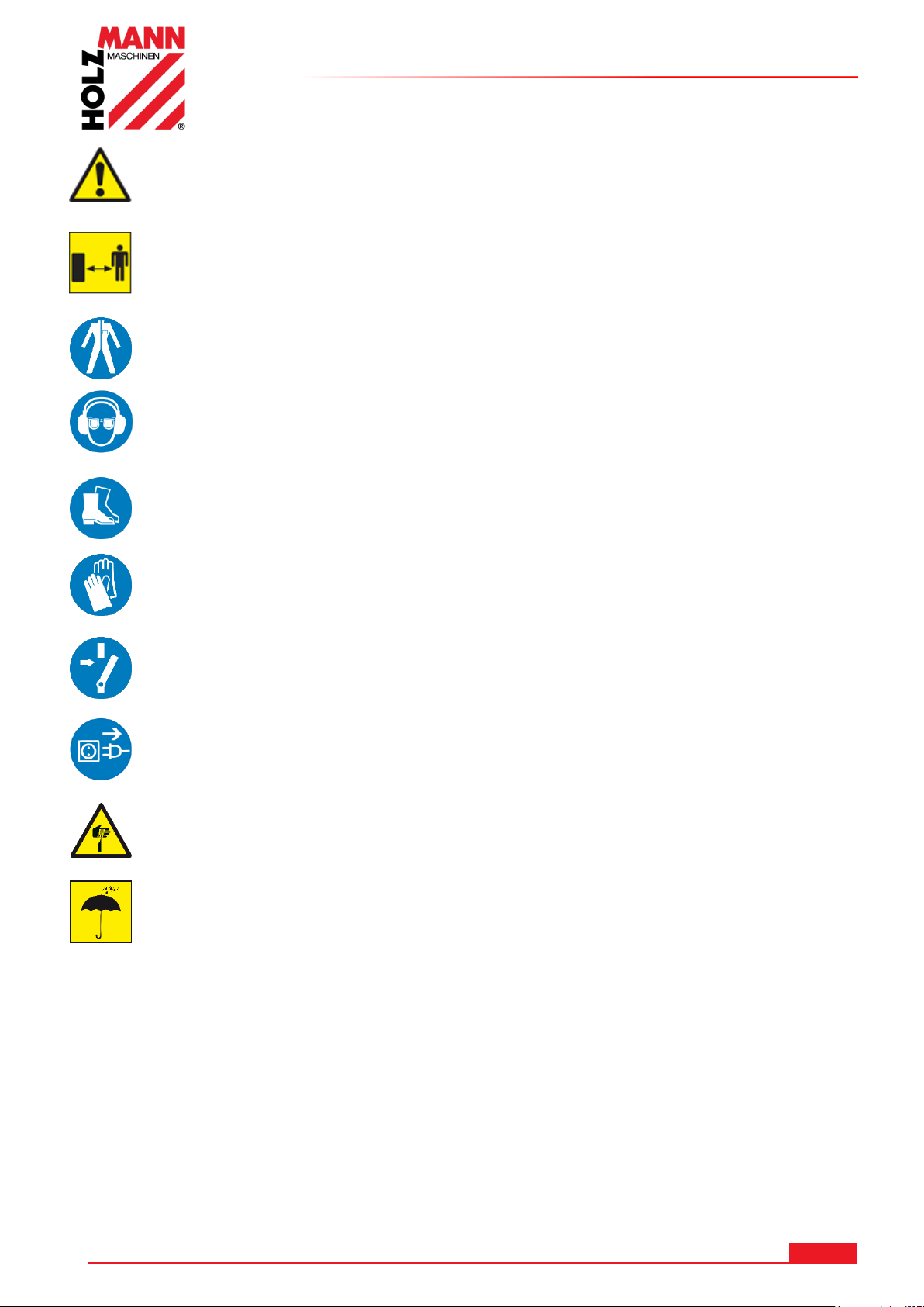
SICHERHEITSZEICHEN / SAFETY SIGNS
DE
SICHERHEITSZEICHEN
BEDEUTUNG DER SYMBOLE
EN
SAFETY SIGNS
DEFINITION OF SYMBOLS
IT
SEGNALI DI SICUREZZA
SIGNIFICATO DEI SIMBOLI
DE
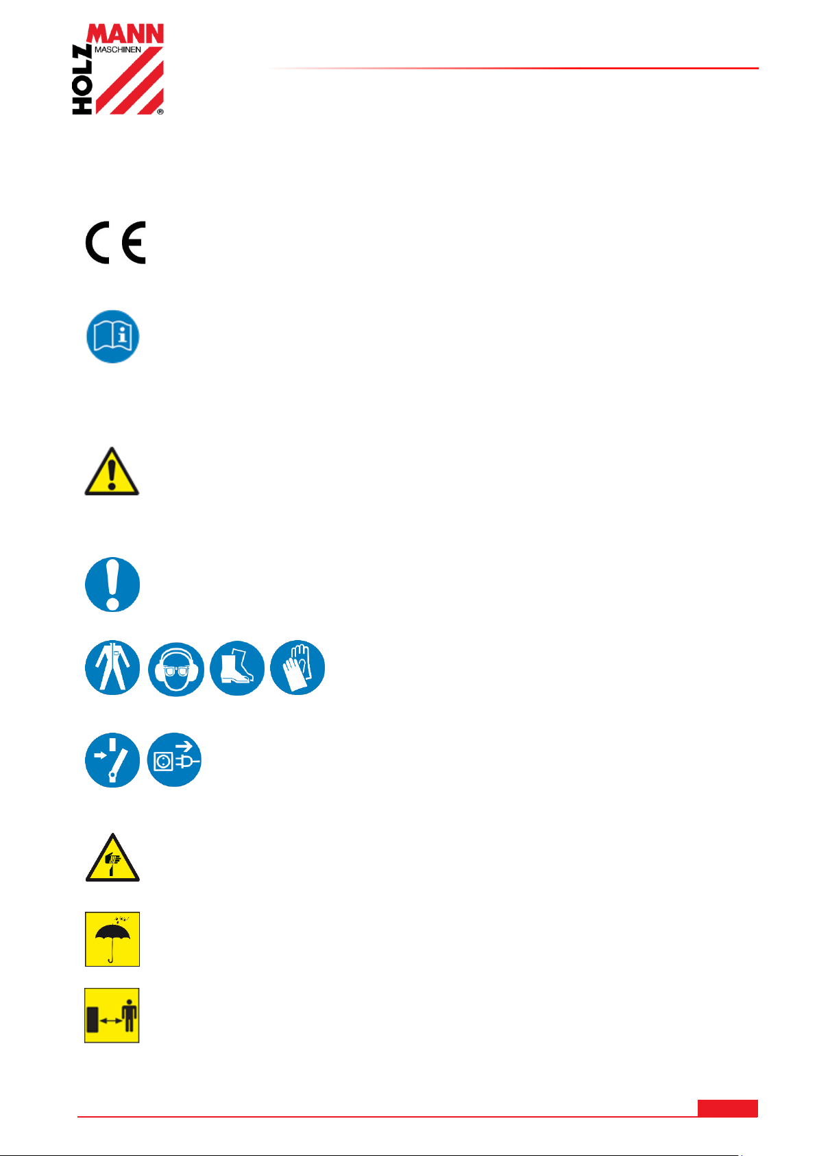
CE-KONFORM:Dieses Produkt entspricht den EG-Richtlinien
EN
EC-CONFORM: This product complies with EC-directives
IT
CONFORMITÀ CE: Questo prodotto è conforme alle direttive CE
DE
ANLEITUNG LESEN! Lesen Sie die Betriebs- und Wartungsanleitung Ihrer Maschine aufmerksam
durch und machen Sie sich mit den Bedienelementen der Maschine gut vertraut um die Maschine
ordnungsgemäß zu bedienen und so Schäden an Mensch und Maschine vorzubeugen.
EN
READ THE MANUAL! Read the user and maintenance manual carefully and get familiar with the
controls in order to use the machine correctly and to avoid injuries and machine defects.
IT
LEGGERE LE ISTRUZIONI! Leggere attentamente le istruzioni d'uso e di manutenzione della
vostra macchina e familiarizzare con gli elementi di comando della macchina per utilizzarla
correttamente e per evitare di danneggiare le persone e la macchina stessa
DE
WARNUNG! Beachten Sie die Sicherheitssymbole! Die Nichtbeachtung der Vorschriften und
Hinweise zum Einsatz der Maschine kann schwere Personenschäden verursachen und zu tödlichen
Unfällen führen.
EN
ATTENTION! Ignoring the safety signs and warnings applied on the machine as well as ignoring
the security and operating instructions can cause serious injuries and even lead to death.
IT
AVVERTENZA! Osservare i simboli di sicurezza! La mancata osservanza delle norme e avvertenze
per l'uso della macchina può comportare gravi danni personali gravi e incidenti mortali.
DE
Allgemeiner Hinweis
EN
General note
IT
Avvertenza generale
DE
Schutzausrüstung tragen!
EN
Protective clothing!
IT
Indossare i dispositivi di protezione!
DE
Maschine vor Wartung und Pausen ausschalten und Netzstecker
ziehen!
EN
Stop and pull out the power plug before any break and engine
maintenance!
IT
Spegnere la macchina prima della manutenzione e delle pause e
scollegare la spina di rete!
DE
Warnung vor Schnittverletzungen!
EN
Warning about cut injuries!
IT
Attenzione alle lesioni da taglio
DE
Vor Nässe schützen!
EN
Protect from moisture!
IT
Proteggersi da bagnato!
DE
Sicherheitsabstand einhalten!
EN
Keep safety distance!
IT
Mantenere la distanza di sicurezza!
2 SICHERHEITSZEICHEN / SAFETY SIGNS
HOLZMANN MASCHINEN GmbH www.holzmann-maschinen.at 6
BS115 / BS128HDR
Page 7
VORWORT (DE)
HOLZMANN MASCHINEN GmbH
AT-4170 Haslach, Marktplatz 4
AUSTRIA
Tel +43 7289 71562 - 0
Fax +43 7289 71562 – 4
4 VORWORT (DE)
Sehr geehrter Kunde!
Diese Betriebsanleitung enthält Informationen und wichtige Hinweise zur Inbetriebnahme und
Handhabung der Metallbandsäge BS 115 / BS128HDR
Folgend wird die übliche Handelsbezeichnung der Maschine (siehe Deckblatt) in dieser
Betriebsanleitung durch die Bezeichnung "Maschine" ersetzt.
Die Betriebsanleitung ist Bestandteil der Maschine und darf nicht entfernt werden.
Bewahren Sie sie für spätere Zwecke auf und legen Sie diese Anleitung der Maschine bei,
wenn sie an Dritte weitergegeben wird!
Bitte beachten Sie die Sicherheitshinweise!
Lesen Sie vor Inbetriebnahme diese Anleitung aufmerksam durch. Der sachgemäße Umgang wird
Ihnen dadurch erleichtert, Missverständnissen und etwaigen Schäden wird vorgebeugt.
Halten Sie sich an die Warn- und Sicherheitshinweise. Missachtung kann zu ernsten Verletzungen
führen.
Durch die ständige Weiterentwicklung unserer Produkte können Abbildungen und Inhalte
geringfügig abweichen. Sollten Sie Fehler feststellen, informieren Sie uns bitte.
Technische Änderungen vorbehalten!
Kontrollieren Sie die Ware nach Erhalt unverzüglich und vermerken Sie etwaige
Beanstandungen bei der Übernahme durch den Zusteller auf dem Frachtbrief!
Transportschäden sind innerhalb von 24 Stunden separat bei uns zu melden.
Für nicht vermerkte Transportschäden kann Holzmann keine Gewährleistung
übernehmen.
Urheberrecht
© 2017
Diese Dokumentation ist urheberrechtlich geschützt. Die dadurch verfassungsmäßigen Rechte
bleiben vorbehalten! Insbesondere der Nachdruck, die Übersetzung und die Entnahme von Fotos
und Abbildungen werden gerichtlich verfolgt.
Als Gerichtsstand gilt das Landesgericht Linz oder das für 4170 Haslach zuständige Gericht.
Kundendienstadresse
HOLZMANN MASCHINEN GmbH www.holzmann-maschinen.at 7
BS115 / BS128HDR
Page 8
5 TECHNIK
1
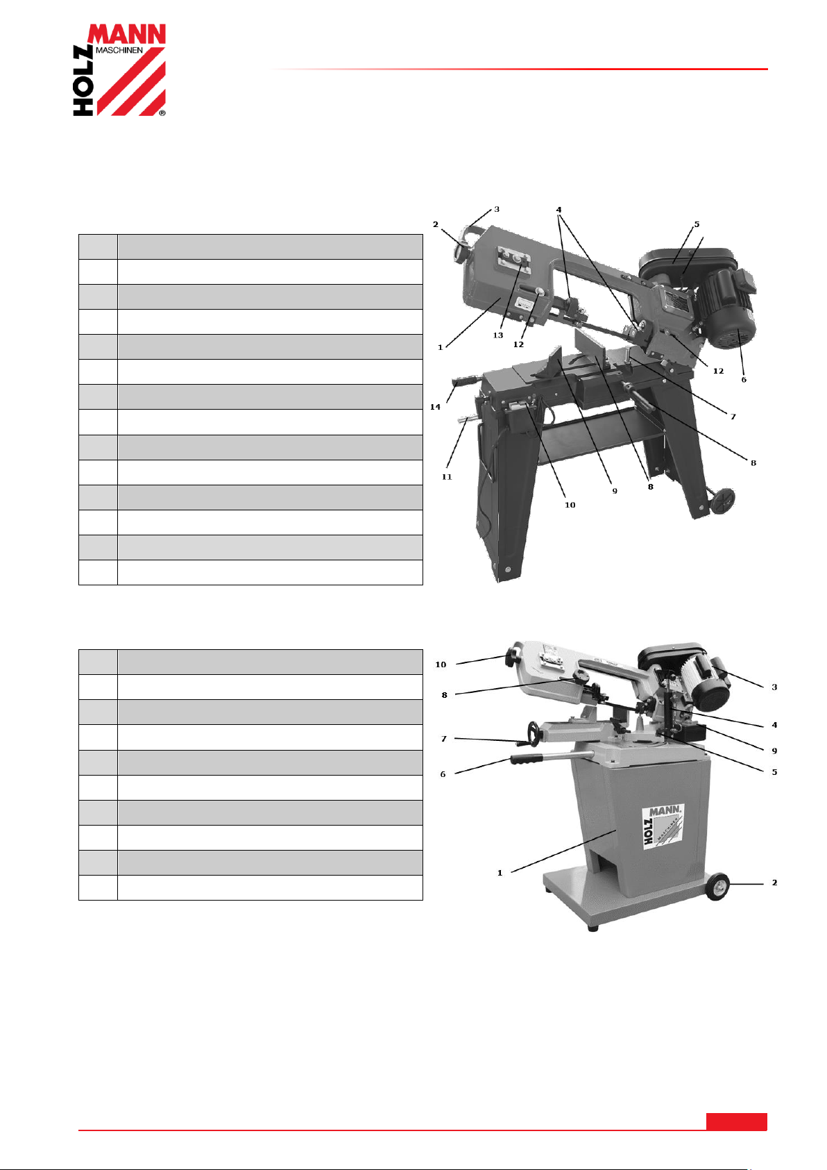
Sägearm
2
Einstellknauf Sägebandspannung
3
Haltebügel für Sägearm
4
einstellbare Sägebandführung
5
Riemenabdeckung
6
Motor
7
Schnitttiefenbegrenzungsschraube
8
Haltebacke winkelverstellbar
9
Spannbacke winkelverstellbar
10
EIN - AUS - Schalter
11
Spannkurbel für Spannbacke
12
Fixierschraube Sägebandführung
13
Einstellung Bandlaufrolle / Sturz
14
Einstellung Vorschubfederung
1
Sägearm
2
Einstellknauf Sägebandspannung
3
Haltebügel für Sägearm
4
einstellbare Sägebandführung
5
Riemenabdeckung
6
Motor
7
Schnitttiefenbegrenzungsschraube
8
Haltebacke winkelverstellbar
9
Spannbacke winkelverstellbar
10
EIN - AUS - Schalter
5.1 Komponenten
5.1.1 BS115
TECHNIK
5.1.2 BS128HDR
HOLZMANN MASCHINEN GmbH www.holzmann-maschinen.at 8
BS115 / BS128HDR
Page 9
5.2 Technische Daten BS115
Netzanschluss
230 / 400 V
Motorleistung
550 W
Schnittgeschwindigkeiten
20-29-50 m/min
Sägebandabmessung
1638x0,6x12,5 mm
max. Ø Rundprofil bei 90°
110 mm
max. Ø Rundprofil bei 45°
75 mm
max. HxB 4-kant Rohr bei 90°
110x140 mm
max. HxB 4-kant Rohr bei 45°
110x75 mm
Abmessungen L x B x H
970x395x945 mm
Gewicht
56 kg
Schall-Leistungspegel LWA
76 dB(A)
Schutzart
IP 20
Netzanschluss
230 / 400 V
Motorleistung
550 W
Schnittgeschwindigkeiten
23 – 34 – 54 m/min
Sägebandabmessung
1640 x 13 x 0,6 mm
max. Ø Rundprofil bei 90°
125 mm
max. Ø Rundprofil bei 45°
95 mm
max. Ø Rundprofil bei 60°
50 mm
max. HxB 4-kant Rohr bei 90°
100 x 150 mm
max. HxB 4-kant Rohr bei 45°
95 x 76 mm
max. HxB 4-kant Rohr bei 60°
50 x 56 mm
Abmessungen L x B x H
1000 x 550 x1100 mm
Gewicht
76 kg
Schall-Leistungspegel LWA
76 dB(A)
Schutzart
IP20
TECHNIK
5.3 Technische Daten BS128HDR
HOLZMANN MASCHINEN GmbH www.holzmann-maschinen.at 9
BS115 / BS128HDR
Page 10
SICHERHEIT
WARN UN G
Verwenden Sie nur für die Maschine zulässige Sägebänder!
Verwenden Sie nie schadhafte Sägebänder!
Benutzen Sie die Maschine niemals mit defekten oder ohne montierte
trennende Schutzeinrichtung
Die Entfernung bzw. Änderung der Sicherheitskomponenten können zu
Schäden am Gerät und schweren Verletzungen führen!
Das Werkstück beim Schneidvorgang immer im Schraubstock fixieren!
Späne und Splitter nie bei laufender Maschine entfernen!
HÖCHSTE VERLETZUNGSGEFAHR!
6 SICHERHEIT
6.1 Bestimmungsmäßige Verwendung
Die Maschine nur in technisch einwandfreiem Zustand sowie bestimmungsgemäß, sicherheitsund gefahrenbewusst benutzen! Störungen, welche die Sicherheit beeinträchtigen können,
umgehend beseitigen lassen! Die vom Hersteller vorgeschriebenen Betriebs-, Wartungs- und
Instandsetzungsbedingungen und die Befolgung der in der Anleitung enthaltenen
Sicherheitshinweise sind einzuhalten.
Es ist generell untersagt, sicherheitstechnische Ausrüstungen der Maschine zu ändern oder unwirksam
zu machen!
Die Maschine ist ausschließlich für folgende Tätigkeiten bestimmt:
Zum Schneiden von Metallen, Guss und Kunststoffen
Für eine andere oder darüber hinausgehende Benutzung und daraus resultierende
Sachschäden oder Verletzungen übernimmt HOLZMANN-MASCHINEN keine
Verantwortung oder Garantieleistung
6.2 Unzulässige Verwendung
Der Betrieb der Maschine unter Bedingungen außerhalb der in dieser Anleitung angegebenen
Grenzen ist nicht zulässig.
Die Maschine ist nicht für den Betrieb unter explosionsgefährlichen Bedingungen bestimmt
Unzulässig ist der Betrieb der Maschine mit Werkstoffen, die nicht ausdrücklich in diesem
Handbuch angeführt werden.
Unzulässig ist der Gebrauch von Werkzeugen, die nicht für den Gebrauch mit der Maschine
geeignet sind.
Etwaige Änderungen in der Konstruktion der Maschine sind unzulässig.
Der Betrieb der Maschine auf eine Art und Weise bzw. zu Zwecken, die den Anweisungen dieser
Bedienungsanleitung nicht zu 100% entspricht, ist untersagt.
Lassen Sie die Maschine nie unbeaufsichtigt, vor allem nicht, wenn Kinder in der Nähe sind!
6.3 Sicherheitshinweise
Warnschilder und/oder Aufkleber an der Maschine, die unleserlich sind oder entfernt
wurden, sind umgehend zu erneuern!
Örtlich geltende Gesetze und Bestimmungen können das Mindestalter des Bedieners
festlegen und die Verwendung dieser Maschine einschränken!
Zur Vermeidung von Fehlfunktionen, Schäden und gesundheitlichen Beeinträchtigungen sind
folgende Hinweise UNBEDINGT zu beachten:
HOLZMANN MASCHINEN GmbH www.holzmann-maschinen.at 10
BS115 / BS128HDR
Page 11
SICHERHEIT
Arbeitsbereich und Boden rund um die Maschine sauber und frei von Öl, Fett und
Materialresten halten!
Für eine ausreichende Beleuchtung im Arbeitsbereich der Maschine sorgen!
Arbeiten Sie nur in gut durchlüfteten Räumen!
Überlasten Sie die Maschine nicht!
Achten Sie bei der Arbeit auf einen stets sicheren Stand.
Halten Sie Ihre Hände während dem Betrieb vom Sägeband fern
Bei Müdigkeit, Unkonzentriertheit bzw. unter Einfluss von Medikamenten, Alkohol
oder Drogen ist das Arbeiten an der Maschine verboten!
Die Maschine darf nur von einer Person bedient werden
Die Maschine darf nur von unterwiesenen Personen (Kenntnis und Verständnis
dieser Betriebsanleitung), die keine Einschränkungen von motorischen Fähigkeiten
verglichen mit üblichen ArbeitnehmerInnen aufweisen, bedient werden.
Unbefugte, insbesondere Kinder, und nicht eingeschulte Personen sind von der
laufenden Maschine fern zu halten!
Achten Sie darauf, dass sich keine weiteren Personen im Gefahrenbereich
(Mindestabstand: 2m) aufhalten
Wenn Sie an der Maschine arbeiten, tragen Sie keinen lockeren Schmuck, weite
Kleidung, Krawatten oder langes, offenes Haar (Haarnetz verwenden!).
Lose Objekte können sich verfangen und zu schwersten Verletzungen führen!
Bei Arbeiten an und mit der Maschine geeignete Schutzausrüstung (enganliegende
Arbeitskleidung, Schutzhandschuhe nach EN 388, Klasse 3111, Schutzbrille,
Gehörschutz und Sicherheitsschuhe S1) tragen!
Die laufende Maschine darf nie unbeaufsichtigt sein! Vor dem Verlassen des
Arbeitsbereiches die Maschine ausschalten und warten, bis die Maschine still steht!
Vor Wartungs- oder Einstellarbeiten ist die Maschine von der Spannungsversorgung
zu trennen!
Stellen Sie sicher, dass die Maschine ausgeschaltet ist, bevor sie an die
Stromversorgung angeschlossen wird
Die Maschine nie mit defektem Schalter verwenden
Verwenden Sie nur unveränderte, in die Steckdose passende Anschlussstecker
(keine Adapter bei schutzgeerdeten Maschinen)
Jedes Mal, wenn Sie mit einer elektrisch betriebenen Maschine arbeiten, ist höchste
Vorsicht geboten! Es besteht Gefahr von Stromschlag, Feuer, Schnittverletzung;
Schützen Sie die Maschine vor Nässe (Kurzschlussgefahr!)
Verwenden Sie Elektrowerkzeuge und –maschinen nie in der Umgebung von
entflammbaren Flüssigkeiten und Gasen (Explosionsgefahr!)
Prüfen Sie regelmäßig das Anschlusskabel auf Beschädigung
Verwenden Sie das Kabel nie zum Tragen der Maschine oder zum Befestigen eines
Werkstückes
Schützen Sie das Kabel vor Hitze, Öl und scharfen Kanten
Vermeiden Sie Körperkontakt mit geerdeten Teilen
Schwere Verletzungen durch scharfe Kanten an der Hand sind möglich.
6.4 Restrisiken
Auch bei Einhaltung aller Sicherheitsbestimmungen und bei bestimmungsgemäßer Verwendung
sind folgende Restrisiken zu beachten:
• Verletzungsgefahr für die Hände/Finger durch das Sägeband während dem Betrieb.
• Verletzungsgefahr/Schnittgefahr durch nicht entgratete Schnittkanten.
• Verletzungsgefahr durch Kontakt mit spannungsführenden Bauteilen.
• Verletzungsgefahr durch Bruch bzw. Herausschleudern des Sägebandes bzw. Teile davon,
v.a. bei Überlastung als auch bei falscher Laufrichtung des Sägebandes.
• Gehörschäden, sofern keine Vorkehrungen seitens des Benutzers für Gehörschutz getroffen
wurden.
• Verletzungsgefahr für das Auge durch herumfliegende Teile, auch mit Schutzbrille.
HOLZMANN MASCHINEN GmbH www.holzmann-maschinen.at 11
BS115 / BS128HDR
Page 12
MONTAGE
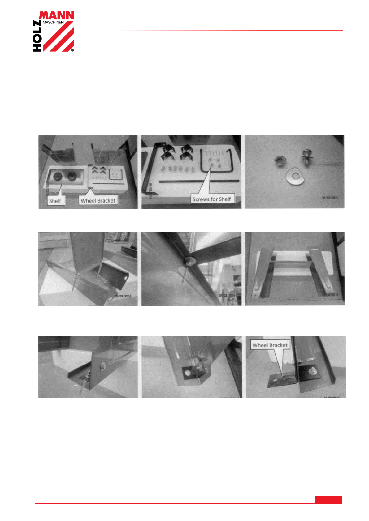
1. Lieferumfang -Montageanbauteile- Schrauben, Scheiben, Muttern
3. Seitenteil ausklappen und die Zwischenablage wie abgebildet 4. Beide Seitenteile montiert
anschrauben. anschrauben
5. Die 2 Eckwinkel an den Bohrungen aufsetzen und anschrauben 6. Radachswinkel gegenüber
mit den 2 Eckwinkel
zusammen anschrauben
7 MONTAGE
Überprüfen Sie nach Erhalt der Lieferung, ob alle Teile in Ordnung sind. Melden Sie
Beschädigungen oder fehlende Teile umgehend Ihrem Händler oder der Spedition. Sichtbare
Transportschäden müssen außerdem gemäß den Bestimmungen der Gewährleistung unverzüglich
auf dem Lieferschein vermerkt werden, ansonsten gilt die Ware als ordnungsgemäß
übernommen.
7.1 BS115
HOLZMANN MASCHINEN GmbH www.holzmann-maschinen.at 12
BS115 / BS128HDR
Page 13
MONTAGE
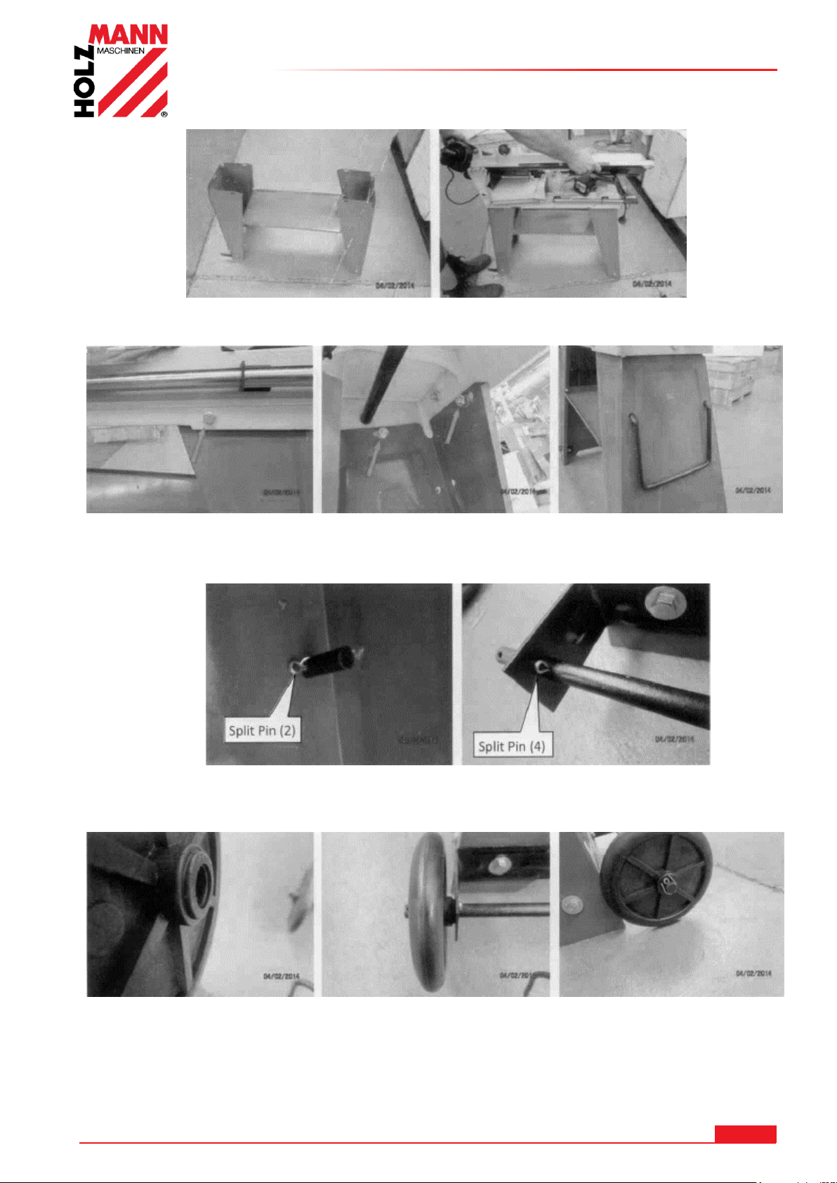
Die Metallbandsäge mit Hilfe einer 2. Person auf das Untergestell vorsichtig auflegen und auf
Abrutschen achten. Motor muss sich auf der Seite der Radhalterung befinden.
8. Den Grundsockel mit dem Untergestell verschrauben. 9. Handgriff einsetzen
10. Den Handgriff innen mit dem Splint sichern. 11. Die Räderachse einschieben und mit
Splinten beidseitig sichern.
12. Das Rad aufsetzen und mit Splint sichern. 13. Das 2. Rad ebenfalls
anschrauben
HOLZMANN MASCHINEN GmbH www.holzmann-maschinen.at 13
BS115 / BS128HDR
Page 14
MONTAGE
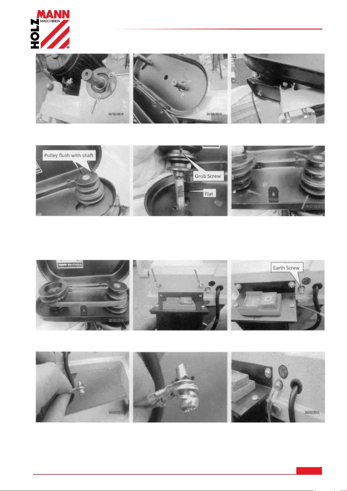
14. Die 2 Schrauben rechts und die Schraube aus der Motorbefestigung herausschrauben.
Die Riemenabdeckung wie abgebildet anschrauben.
15. Die Motorriemenscheibe -linkes Bild- mit Passfedernut auf die Motorwelle aufsetzen. Die
Antriebsriemenscheibe -Bild mittig- wie abgebildet auf die Antriebswelle mit Madenschraube auf
die abgeflachte Stelle richtig aufsetzen. Beide Riemenscheiben mit den Madenschrauben
festschrauben.
17. Den Keilriemen aufsetzen. 18. Die Schalteinheit anschrauben.
Elektrische Arbeiten nur von fachlich qualifizierten Personen ausführen lassen
19. Die 2 Erdungskabel wie abgebildet anschrauben.
HOLZMANN MASCHINEN GmbH www.holzmann-maschinen.at 14
BS115 / BS128HDR
Page 15
MONTAGE
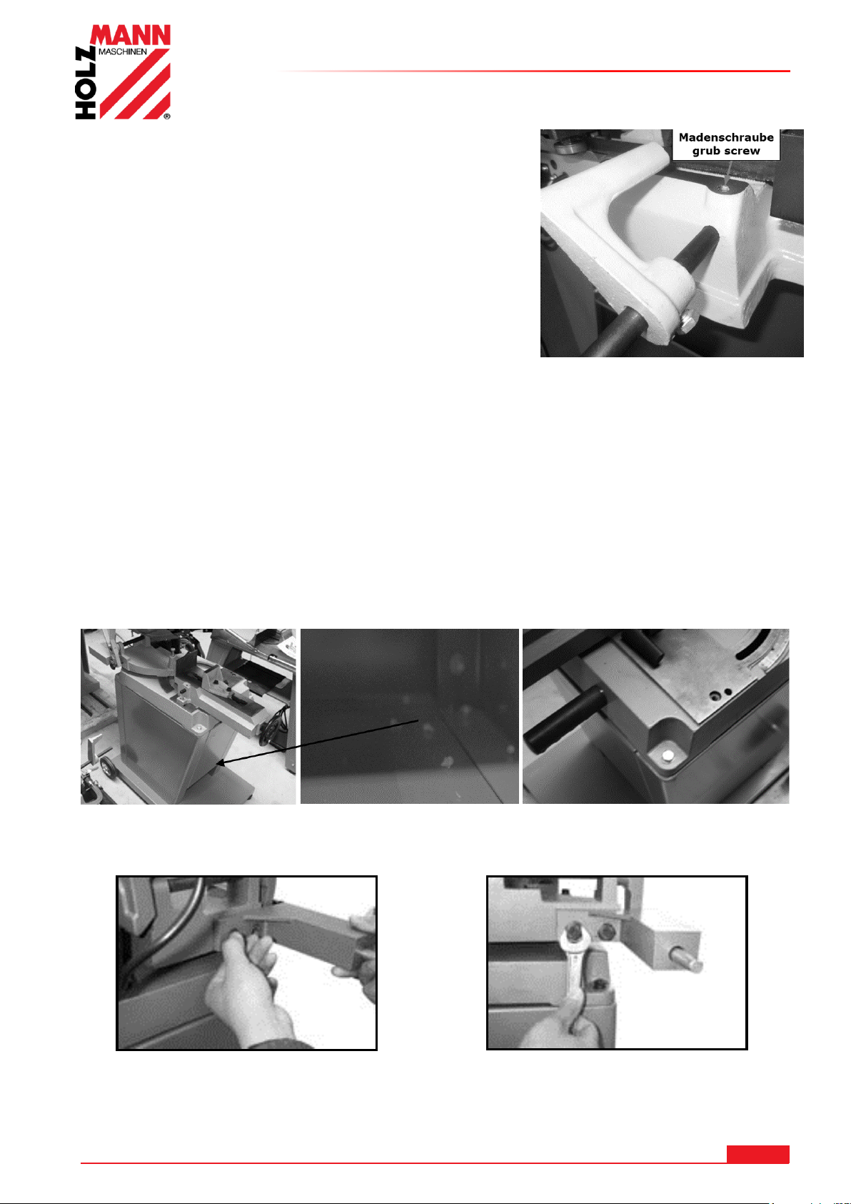
20. Endanschlag anbauen.
Den Führungsrundstahl in den Sockel einschieben und mit
der Madenschraube festziehen.
Den Endanschlag auf den Führungsrundstahl montieren
7.2 BS128HDR
Die BS 128HDR ist im Prinzip fertig zusammengebaut.
Sie müssen lediglich das Untergestell zusammenbauen.
Montieren Sie dazu als erstes die Räder.
Danach muss das Untergestell zusammengebaut werden (Verschraubung
innen mit dem Fahrgestell).
Am Schluss wird die Bandsäge auf das Untergestell gesetzt und mit Schrauben befestigt.
Anschrauben der Pufferfederung
Die Federhalterung wird an der Konsole wie abgebildet angeschraubt
HOLZMANN MASCHINEN GmbH www.holzmann-maschinen.at 15
BS115 / BS128HDR
Page 16
MONTAGE
AC HT UNG
Bei Arbeiten an einer nicht geerdeten Maschine: Schwere
Verletzungen durch Stromschlag im Falle einer Fehlfunktion möglich!
Daher gilt: Maschine muss an einer geerdeten Steckdose betrieben werden.
WA RN UN G
Das Hochheben und der Transport der Maschine darf nur durch
qualifiziertes Personal erfolgen mit entsprechender Ausrüstung
durchgeführt werden.
7.3 Der Arbeitsplatz
Wählen Sie einen passenden Platz für die Maschine. Beachten Sie dabei die
Sicherheitsanforderungen. Der Boden muss fest, eben und schwingungsresistent sein sowie
zumindest 2x das Nettogewicht der Maschine tragen können.
Der gewählte Platz muss einen passenden Anschluss an das elektrische Netz gewährleisten.
Man muss außerdem einen Abstand von mindestens 0.8 m um die Maschine rundum sichern. Vor
und hinter der Maschine muss für notwendigen Abstand für die Zufuhr von langen Werkstücken
gesorgt werden.
7.4 Transport / Ausladen der Maschine
Herausheben aus der Verpackung zur Montage und Positionieren auf dem Arbeitsplatz: Nur
mittels geeigneter Hebeeinrichtung!
Beachten Sie, dass sich etwaig verwendete Hebeeinrichtungen (Kran, Stapler, Hebegurt etc.) in
einwandfreiem Zustand befinden müssen.
Zum Manövrieren der Maschine in der Verpackung kann auch ein Palettenhubwagen bzw. ein
Gabelstapler verwendet werden.
Beseitigen Sie das Konservierungsmittel, das zum Korrosionsschutz der Teile ohne Anstrich
aufgetragen ist. Das kann mit den üblichen Lösungsmitteln geschehen. Dabei keine
Nitrolösungsmittel oder ähnliche Mittel und in keinem Fall Wasser verwenden.
7.5 Elektrischer Anschluss
Folgende Anweisungen richten sich an einen Elektrofachmann. Der Anschluss der Maschine ist
ausschließlich durch einen Elektrofachmann durchzuführen!
1. Der elektrische Anschluss der Maschine ist für den Betrieb an einer geerdeten Steckdose
vorbereitet!
2. Der Anschlussstecker darf nicht manipuliert werden!
3. Der Erdungsleiter ist gelb-grün ausgeführt!
4. Das Speisestromnetz muss mit 16A abgesichert sein.
5. Überprüfen Sie, ob die Netzspannung mit den Anforderungen der Maschine übereinstimmt.
6. Prüfen Sie nach dem elektrischen Anschluss die korrekte Laufrichtung (400V)
7. Wenn die Maschine in die falsche Richtung läuft (400V), sind zwei leitende Phasen zu
tauschen .
8. Im Falle einer Reparatur oder eines Austausches darf der Erdungsleiter nicht an eine unter
Spannung stehende Dose angeschlossen werden!
9. Überzeugen Sie sich, dass ein etwaiges Verlängerungskabel in gutem Zustand und für die
Leistungsübertragung geeignet ist. Ein unterdimensioniertes Kabel verringert die
Leistungsübertragung und erwärmt sich stark.
10. Ein beschädigtes Kabel ist umgehend zu erneuern!
HOLZMANN MASCHINEN GmbH www.holzmann-maschinen.at 16
BS115 / BS128HDR
Page 17
MONTAGE
HI NW EI S
Der Betrieb ist nur mit Fehlerstromschutzeinrichtung
(RCD mit maximalem Fehlerstrom von 30mA) zulässig.
HI NW EI S
Verwenden Sie ausschließlich zulässige
Verlängerungskabel mit dem, in der folgenden Tabelle
erklärten, Litzenquerschnitt.
Spannung
Verlängerung
Litzenquerschnitt
220 V-240 V
50 Hz
<27 m
1,5 mm
2
<44 m
2,5 mm
2
<70 m
4,0 mm
2
<105 m
6,0 mm
2
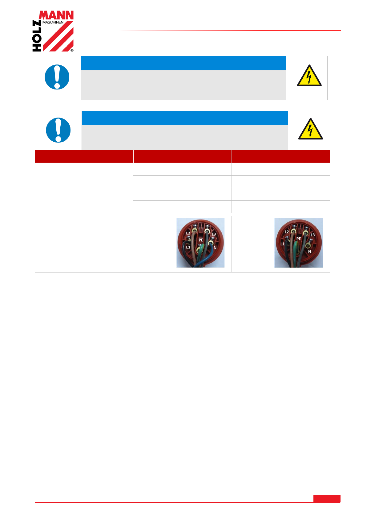
Steckeranschluss 400V:
5-adrig:
mit
N-Leiter
4-adrig:
ohne
N-Leiter
HOLZMANN MASCHINEN GmbH www.holzmann-maschinen.at 17
BS115 / BS128HDR
Page 18
BETRIEB
WARN UN G
Führen Sie sämtliche Umrüst- und Einstellarbeiten nur nach
Trennung vom elektrischen Netz durch!
HI NW EI S
Vor Arbeitsbeginn die Metallkreissäge prüfen:
Allgemeiner technischer Zustand der Maschine
Sicherheitseinrichtungen vorhanden und in Ordnung
Sägeband auf Abnützung prüfen und ggf. erneuern
Beweglichen Teile sind nicht blockiert
Alle Komponenten auf richtigen Sitz und Funktionsweise, insbesondere
die Schrauben des Sägeblattschutzes und des Hebels kontrollieren!
Alle Werkzeuge zur Wartung / Instandhaltung von der Maschine
entfernt.
Sägeblattschutz so nahe als möglich zum Werkstück gestellt.
Vor jedem Schnitt überprüfen:
Winkel richtig eingestellt?
Schraubstock adäquat fixiert?
Vergewissern Sie sich, dass das zu bearbeitende Material
ordnungsgemäß im Schraubstock befestigt ist.
Vergewissern Sie sich, dass das Kühlmittel ordnungsgemäß zirkuliert
Sägebandlaufrichtung
Lange, überstehende Werkstücke müssen mit einem Stützbock gestützt
werden
Lassen Sie den Motor immer auf volle Drehzahl laufen, bevor Sie zu
Schneiden beginnen
Die Maschine nie mit angedrücktem Sägeband starten!
8 BETRIEB
Betreiben Sie die Maschine nur im einwandfreien Zustand. Vor jedem Betrieb ist eine
Sichtprüfung der Maschine durchzuführen. Sicherheitseinrichtungen, elektrische Leitungen und
Bedienelemente sind genauestens zu kontrollieren. Prüfen Sie Schraubverbindungen auf
Beschädigung und festen Sitz.
8.1 Betriebshinweise
HOLZMANN MASCHINEN GmbH www.holzmann-maschinen.at 18
BS115 / BS128HDR
Page 19
BETRIEB
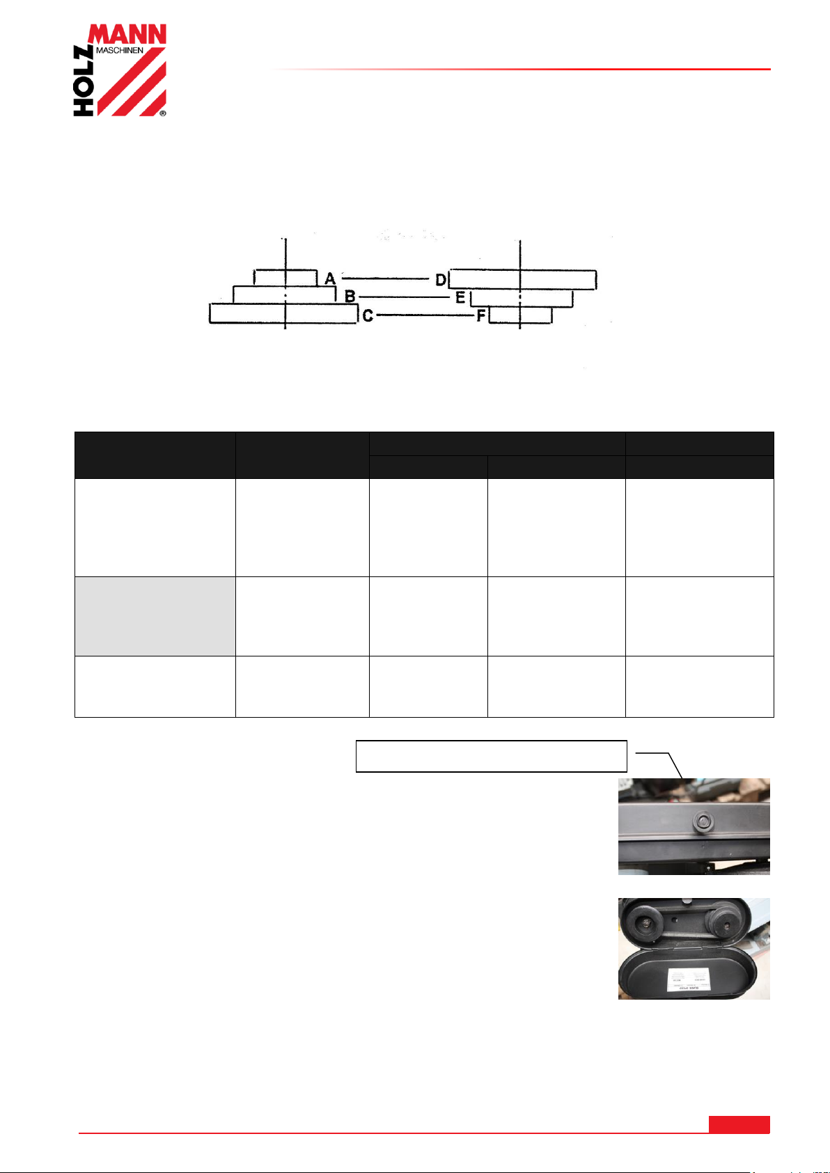
Material
Geschwindigkeit
(m/min)
Riemenstellung
Motorscheibe
Antriebsscheibe
Sägeband
Edelstahl
Nirosta ®
Werkzeugstahl
Legierter Stahl
Lagerbronze
20 A D
Bi-Metall
Baustahl
Eisen
Flussstahl
Thomasstahl
29 B E
Bi-Metall
Messing
Aluminium
Ähnliche Materialien
50 C F
HSS
Motorriemenscheibe Antriebsriemenscheibe
Knopfschraube od. Blechschraube
8.2 BS115
8.2.1 Wählen der Sägebandgeschwindigkgeit
Das Sägeband wird über Riemenantrieb angetrieben. Passen Sie die Sägebandgeschwindigkeit
dem zu schneidenden Material an
Wählen Sie den Vorschub laut der folgenden Tabelle.
Die Schraube am Deckel abschrauben und den Deckel hochklappen.
Die beiden Schrauben an der Motorhalterung lockern.
Der Riemen wird nun auf die entsprechende Position von der Tabelle
- Tabelle auch im Deckel sichtbar- positioniert.
Die beiden Schrauben an der Motorhalterung wieder festziehen und
den Deckel wieder schließen und verschrauben.
HOLZMANN MASCHINEN GmbH www.holzmann-maschinen.at 19
BS115 / BS128HDR
Page 20
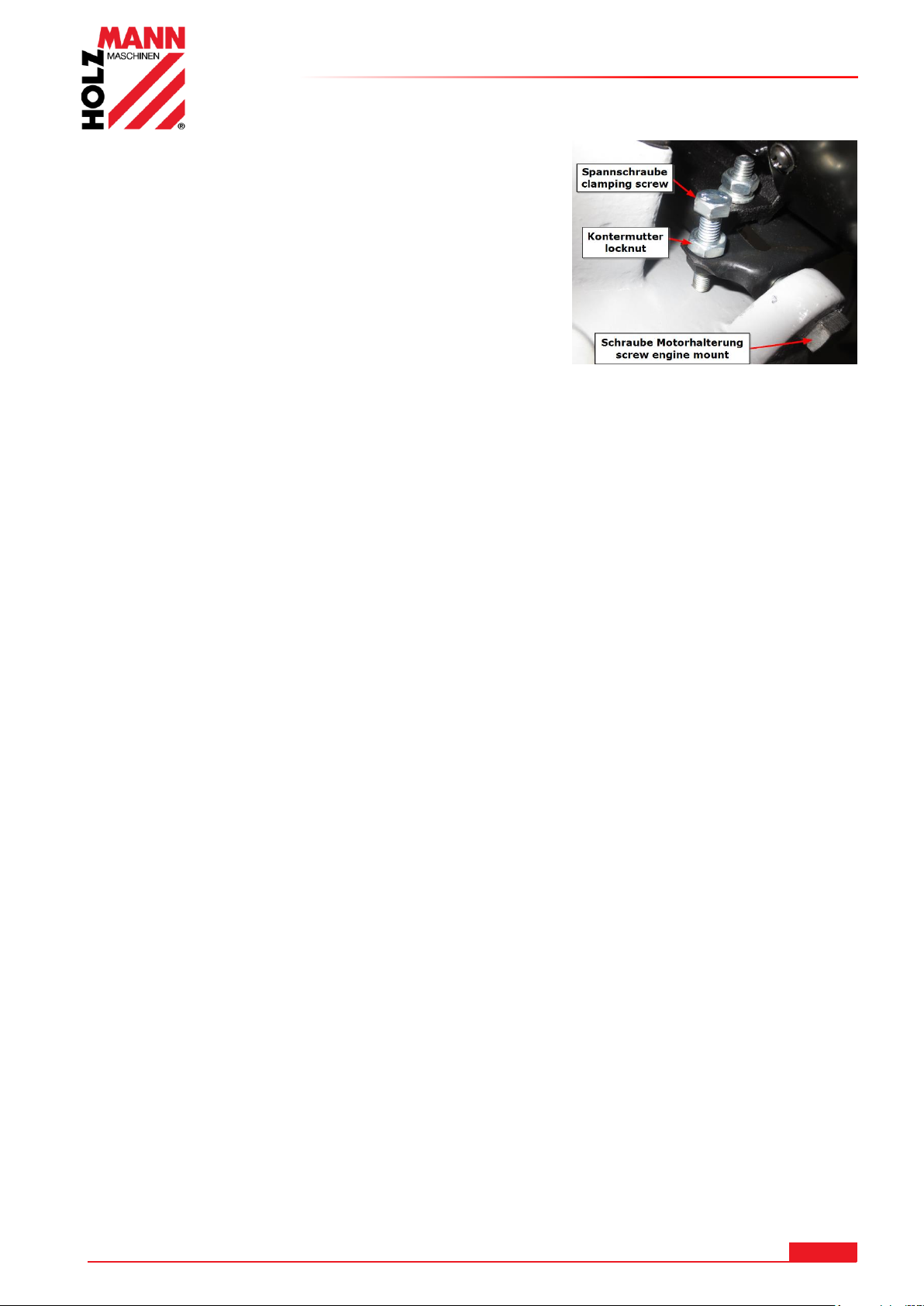
8.2.2 Einstellung der Keilriemenspannung
Die beiden Schrauben an der Motorhalterung sind leicht
gelockert.
Die Kontermutter lockern und mit der Spannschraube
den Keilriemen auf ca. 2-5mm Spiel einstellen.
Die Kontermutter festziehen.
Auf beiden Seiten die Schrauben der Motorhalterung
festziehen.
DIE ZAHNUNG DES SÄGEBANDES SOLLTE DEM ZU SCHNEIDENDEN MATERIAL
EBENFALLS ANGEPASST WERDEN:
1. Je dünner / schmäler das Werkstück, desto höhere Zahnung
2. Grundregel: es sollten zu jedem Zeitpunkt mindestens 3 Zähne im Material arbeiten
BETRIEB
8.2.3 Einstellung des Gehrungswinkels
Lösen Sie die Befestigung der Haltebacke (8)
Stellen sie die Haltebacke auf den gewünschten Winkel ein.
8.2.4 Einspannen des Werkstücks
Legen Sie das Werkstück an der Haltebacke an und spannen Sie es mit der Spannbacke (9). Die
Spannbacke kann mit der Kurbel (11) nach verstellt werden.
8.2.5 Einstellen der Sägebandspannung
Prüfen Sie die Sägebandspannung: Üben Sie mit dem Daumen in der Mitte des Sägebandes
leichten Druck aus – es sollte ca. 1mm nachgeben.
Ist das Sägeband nicht richtig gespannt, müssen Sie die Spannung mit dem Einstellknauf (2)
nachjustieren.
8.2.6 Einstellen des Vorschub
Mit dem Handgriff der Vorschubfederung (14) kann durch Drehen nach rechts die Feder gespannt
und der Vorschub verringert werden. Durch Drehen nach links wird der Vorschub erhöht.
HOLZMANN MASCHINEN GmbH www.holzmann-maschinen.at 20
BS115 / BS128HDR
Page 21
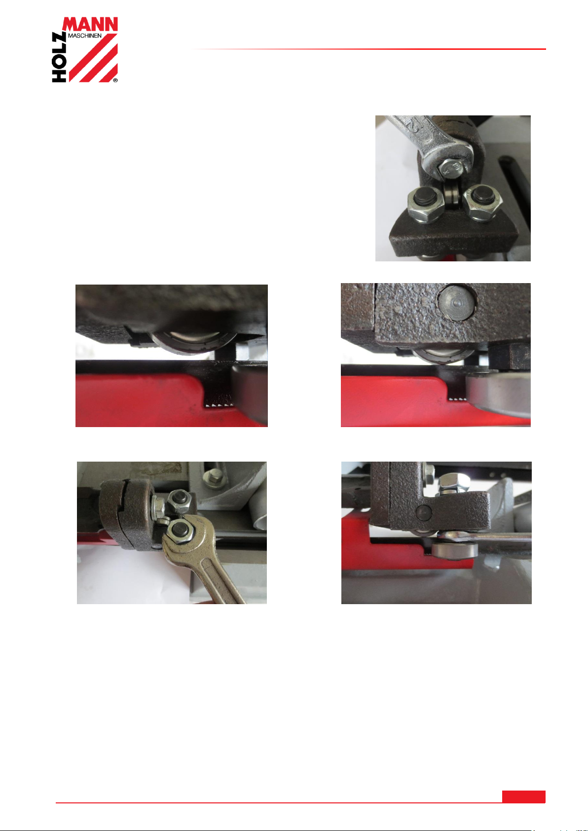
8.2.7 Einstellen der Sägebandführung vertikal zum Schnittgut
Die linke Sägebandführung mit der
Schraube für die Fixierung leicht lockern.
Das Spiel durch Absenken der Sägebandführung mit der Lagerrolle auf das Sägeband auf Null
ausgleichen.
Die Muttern an beiden seitlichen
Führungsrollen mit einem Gabelschlüssel
SW17 leicht lockern.
Mit einem Gabelschlüssel SW 12 wird mithilfe
der Exzenterschraube die Lagerrolle nach
außen oder innen verstellt.
Auf beiden Seiten den Vorgang wiederholen bis
kein Spiel mehr zwischen den Lagerrollen ist.
Das Sägeband sollte mittig auf der oberen
Lagerrolle ausgerichtet sein.
ACHTUNG: Die beiden unteren seitlichen
Lagerrollen nicht zu fest klemmen !
Nachdem beide Lagerrollen spielfrei eingestellt sind, die beiden Muttern oben an den
Führungsrollen wieder festziehen.
BETRIEB
HOLZMANN MASCHINEN GmbH www.holzmann-maschinen.at 21
BS115 / BS128HDR
Page 22
BETRIEB
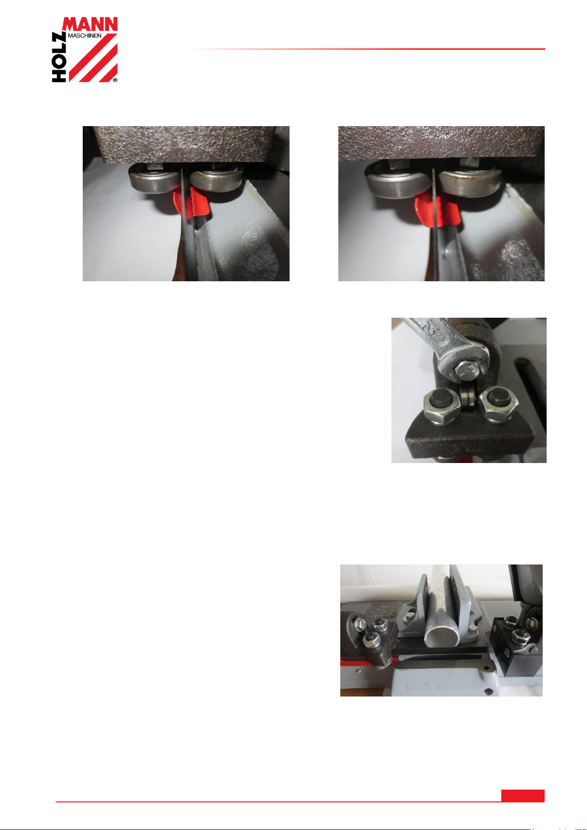
Beispiel für eine perfekte Einstellung der Sägebandführung:
Das Sägeband hat noch zu viel Spiel und ist
deshalb noch schräg zwischen den seitlichen
Lagerrollen.
Das Sägeband ist ohne Spiel ganz vertikal
zwischen den seitlichen Lagerrollen.
ACHTUNG:
Vor dem Festziehen der Sägebandführung prüfen ob das
Sägeband darunter perfekt vertikal eingestellt ist und die
Sägebandführung entsprechend vertikal nachkorrigieren.
Die Sägebandführung mit der Schraube für die Fixierung
wieder festziehen.
HINWEIS: Mit einer 90° Winkellehre oder mit einem rechtwinkligem Werkstück die 90°
Stellung der Sägebandführung prüfen.
Diesen Vorgang auf der rechten Sägebandführung wiederholen falls das Sägeband nicht vertikal
genau geführt wird.
HINWEIS: Die Sägebandführungen links / rechts möglichst nahe an das Werkstück schieben.
Durch Lockern der Fixiermuttern (12) können die
Sägebandführungen beidseitig verschoben werden.
ACHTUNG: Schräge Schnitte entstehen durch nicht genau vertikal eingestellte
Sägebandführungen und zu viel Spiel zwischen den seitlichen Lagerrollen !
HOLZMANN MASCHINEN GmbH www.holzmann-maschinen.at 22
BS115 / BS128HDR
Page 23
BETRIEB
HI NW EI S
Lassen Sie den Motor voll anlaufen, bevor Sei zu Schneiden beginnen.
8.3 Bedienung
Hinweise vor Inbetriebnahme:
Bevor Sie mit dem Sägen beginnen, vergewissern Sie sich:
- dass alle Maschinenkomponenten in einwandfreiem Zustand sind
- dass Sie für das Material die richtige Sägebandgeschwindigkeit eingestellt haben und das
richtige Sägeblatt verwenden
- dass das Werkstück im richtigen Winkel ordnungsgemäß eingespannt ist
- dass das Werkstück sicher aufliegt. Bei längeren Werkstücken sind diese durch eine Unterlage
zu stützen (z.B. Rollbock)
- dass das Sägeband richtig eingestellt ist (Bandspannung sowie vertikal)
- dass der Sägearm hochgeschwenkt ist und das Werkstück nicht berührt
- dass keinerlei Werkzeuge mehr auf dem Maschinenbett liegen
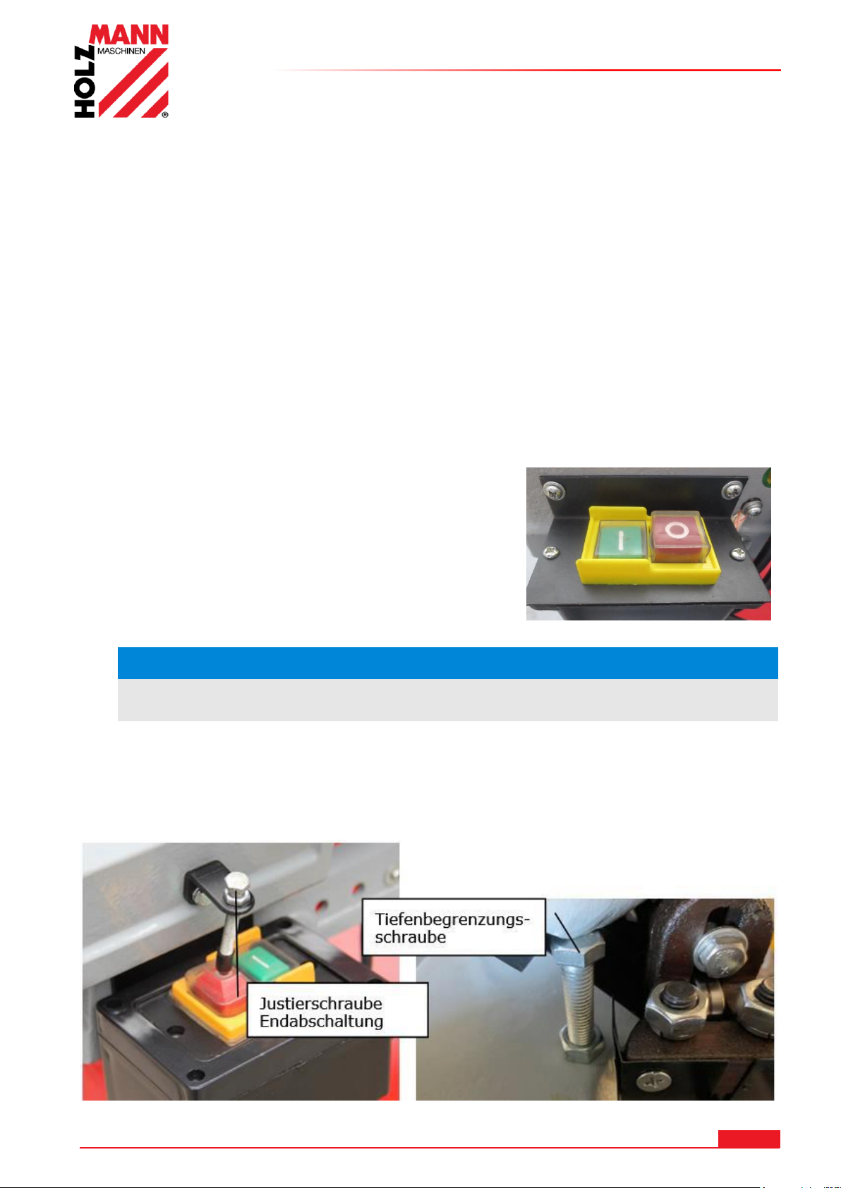
8.3.1 EIN- /AUS schalten
Die Maschine lässt sich über den grünen EIN-Schaltknopf einschalten und mit den roten AUSSchaltknopf ausschalten.
- Führen Sie den Sägearm mit dem Haltebügel (3) zum
Werkstück.
- Lassen Sie den Sägearm durch sein Eigengewicht durch
das Material arbeiten.
- Üben Sie keinen Druck aus. Die Säge schaltet sich nach
Durchschneiden des Materials automatisch durch
Auslösung des AUS-Schaltknopf aus.
Bei Erreichen der untersten max. Schnitttiefe schaltet die Maschine mit dem AUS-Schaltknopf
automatisch ab.
Das automatische Abschalten kann durch nachjustieren der Tiefenbegrenzungsschraube
nachgestellt werden.
HOLZMANN MASCHINEN GmbH www.holzmann-maschinen.at 23
BS115 / BS128HDR
Page 24
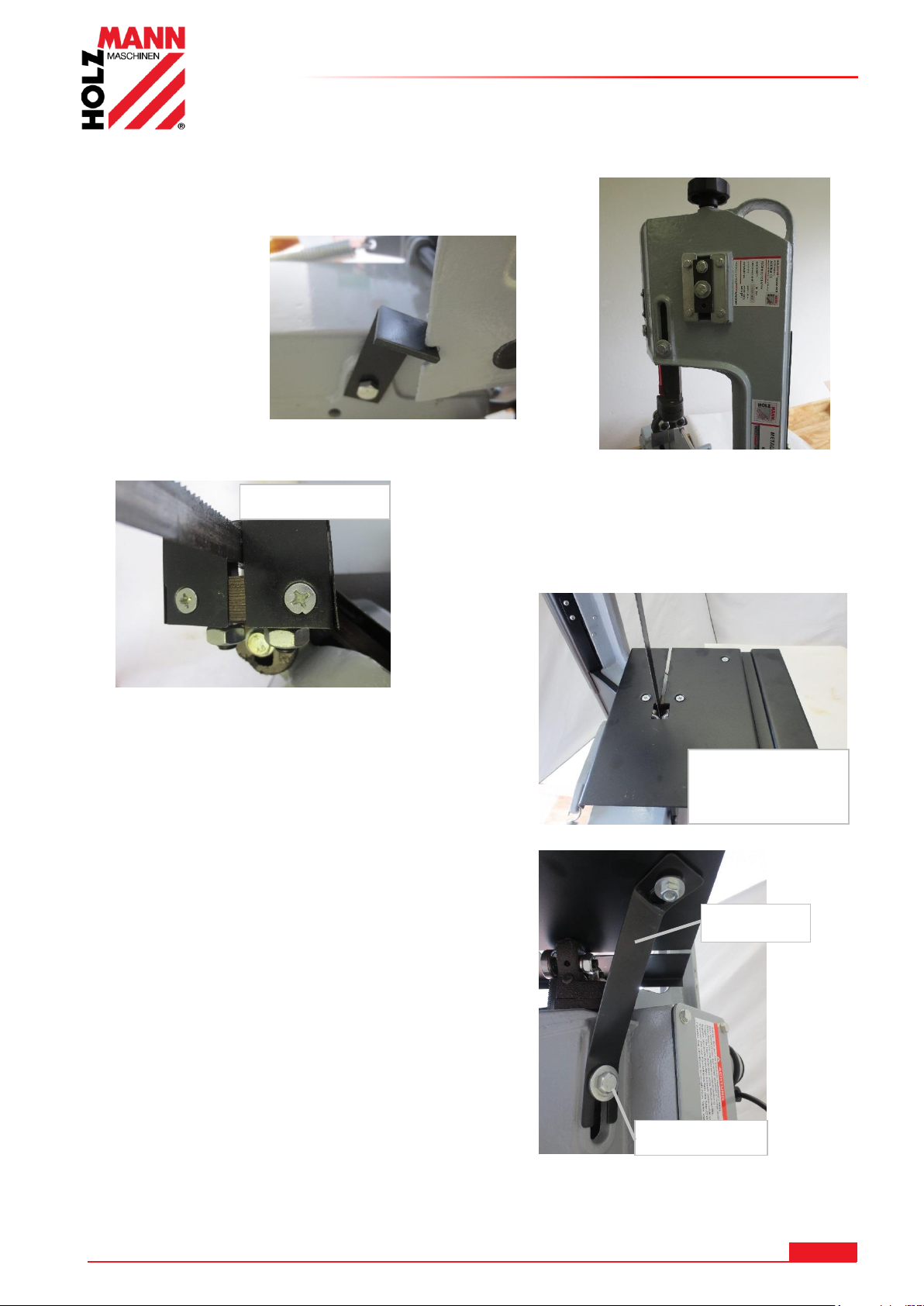
8.3.2 Bandsäge vertikal betrieben
Den Bandsägearm in die 90° Position hochheben und
an der Grundkonsole mit dem Fixierwinkel
festklemmen.
Die Schutzabdeckung abschrauben.
Die Arbeitstischplatte mit den beiden Schrauben auf
die Sägebandführung anschrauben.
Die Fixierschraube (12) der Sägebandführung
lockern.
Den Stützbügel bei der Fixierschraube (12)
einschieben.
An der Tischplatte mit der Senkschraube oben und
der Scheibe und Mutter unten anschrauben.
Die obere Sägebandführung kann durch Lösen der
Fixiermutter (12) und einschrauben in die 2.
Gewindebohrung tiefer geschoben werden.
Dadurch wird das Sägeband noch besser geführt.
Arbeitstischplatte
für
Vertikalschnitte
Schutzabdeckung
Fixierschraube
Stützbügel
BETRIEB
HOLZMANN MASCHINEN GmbH www.holzmann-maschinen.at 24
BS115 / BS128HDR
Page 25
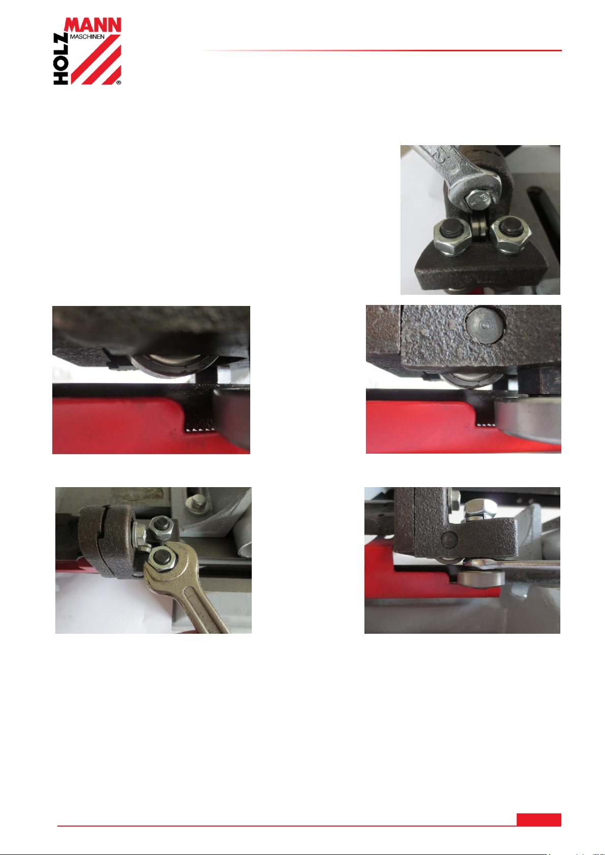
8.4 BS128HDR
Die linke Sägebandführung mit der
Schraube für die Fixierung leicht
lockern.
Das Spiel durch Absenken der Sägebandführung mit der Lagerrolle auf das Sägeband auf Null
ausgleichen.
Die Muttern an beiden seitlichen
Führungsrollen mit einem Gabelschlüssel
SW17 leicht lockern.
Mit einem Gabelschlüssel SW 12 wird mithilfe der
Exzenterschraube die Lagerrolle nach
außen oder innen verstellt.
Auf beiden Seiten den Vorgang wiederholen bis kein
Spiel mehr zwischen den Lagerrollen ist.
Das Sägeband sollte mittig auf der oberen Lagerrolle
ausgerichtet sein.
ACHTUNG: Die beiden unteren seitlichen Lagerrollen
nicht zu fest auf das Sägeband klemmen !
Nach dem beide Lagerrollen spielfrei eingestellt sind, die beiden Muttern oben an den
Führungsrollen wieder festziehen.
8.4.1 Einstellen der Sägebandführung vertikal zum Schnittgut
BETRIEB
HOLZMANN MASCHINEN GmbH www.holzmann-maschinen.at 25
BS115 / BS128HDR
Page 26
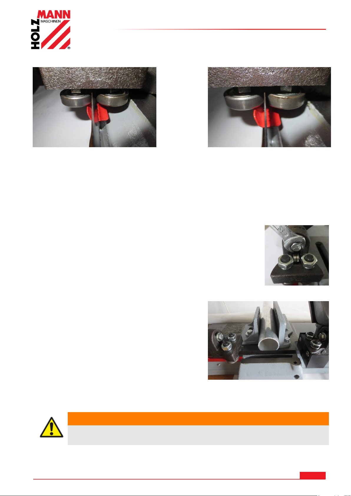
BETRIEB
Beispiel für eine perfekte Einstellung der Sägebandführung:
Das Sägeband hat noch zu viel Spiel und ist
deshalb noch schräg zwischen den seitlichen
Lagerrollen.
Das Sägeband ist fast ohne Spiel ganz
vertikal zwischen den seitlichen Lagerrollen.
WA RN UN G
Führen Sie sämtliche Umrüstarbeiten bei Trennung vom
elektrischen Netz durch!
Mit einer Winkellehre oder mit einem rechtwinkligem Werkstück die 90° Sägebandführung prüfen.
Diesen Vorgang auf der rechten Sägebandführung wiederholen falls das Sägeband nicht vertikal
genau geführt wird.
Wenn das Sägeband exakt eingestellt ist, die Sägebandführung gut
festziehen.
HINWEIS: Die Sägebandführungen links / rechts möglichst nahe an das
Werkstück schieben.
Durch Lockern der Klemmschraube für Sägebandführung
(8) kann die linke Sägebandführung verschoben
werden.
Die rechte Sägebandführung kann durch lockern der
Schraube verschoben werden.
ACHTUNG: Schräge Schnitte entstehen durch nicht genau vertikal eingestellte
Sägebandführungen und zu viel Spiel zwischen den seitlichen Lagerrollen!
HOLZMANN MASCHINEN GmbH www.holzmann-maschinen.at 26
BS115 / BS128HDR
Page 27
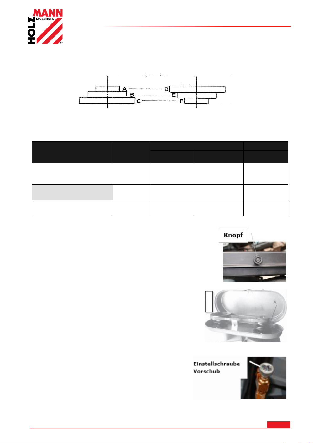
BETRIEB
Material
Geschwindi
gkeit
(m/min)
Riemenstellung
Motorscheibe
Antriebsscheibe
Sägeband
Edelstahl - Nirosta ®
Werkzeugstahl - Legierter
Stahl - Lagerbronze
23 A D
Bi-Metall
Baustahl - Eisen
Flussstahl - Thomasstahl
34 B E
Bi-Metall
Messing - Aluminium
Ähnliche Materialien
54 C F
HSS
Motorriemenscheibe Antriebsriemenscheibe
8.4.2 Wählen der Sägebandgeschwindikgeit
Das Sägeband wird über Riemenantrieb angetrieben. Passen Sie die Sägebandgeschwindigkeit
dem zu schneidenden Material an
Wählen Sie den Vorschub laut der folgenden Tabelle.
8.4.3 Einstellung der Sägebandgeschwindigkeit
Öffnen Sie den Deckel, indem Sie beim Knopf anziehen und den
Deckel hochheben.
Nun können Sie anhand der Drehzahl-Tabelle im Deckel die
Schnittgeschwindigkeit ändern.
Die Riemenscheibe leicht drehen und den Keilriemen in die
vorgesehene Scheibennut eindrehen.
ACHTUNG:
Der Keilriemen muss mit den gegenüberliegenden Scheiben
immer in der gleichen Ebene sein.
8.4.4 Einstellen des Vorschub
Der Vorschub lässt sich über die Einstellschraube auf dem
hydraulischem Senkzylinder (4) einstellen.
Wählen Sie den Vorschub laut der folgenden Tabelle.
HOLZMANN MASCHINEN GmbH www.holzmann-maschinen.at 27
BS115 / BS128HDR
Page 28
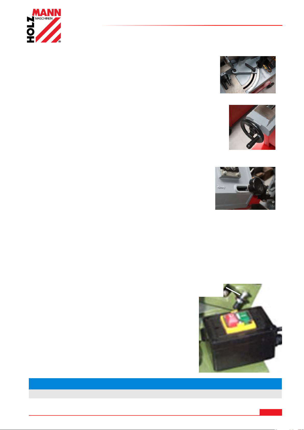
8.4.5 Einstellung des Gehrungswinkels
HI NW EI S
Lassen Sie den Motor voll anlaufen, bevor Sei zu Schneiden beginnen.
Justierschraube Endabschaltung
Lösen Sie die Klemmschraube (5).
Nun können Sie den gesamten Sägearm verschieben.
Durch Anziehen der Klemmschraube (5) wird dieser wieder fixiert.
8.4.6 Einspannen des Werkstücks
Legen Sie das Werkstück in den Schraubstock und ziehen Sie ihn mit
dem Handrad (7) zu.
BETRIEB
8.4.7 Einstellen der Sägebandführung
Stellen Sie die Führung so ein, dass sie sich etwa 2cm vor dem
Werkstück befindet.
Lösen Sie das Handrad (8) und verschieben Sie die Führung.
Ziehen Sie das Handrad danach wieder an.
8.4.8 Einstellen der Sägebandspannung
Das Sägeband mit dem Einstellknopf (10) auf Spannung (2 - 3mm Test) einstellen.
Nach einem kurzen Testlauf nachprüfen und gegebenenfalls nachspannen.
8.4.9 Starten / Stoppen
EIN / AUS Schalten:
Die Maschine lässt sich über den grünen EIN-Schaltknopf einschalten und mit den roten AUSSchaltknopf ausschalten.
Das automatische Abschalten kann durch nachjustieren der
Endabschaltungsschraube nachgestellt werden.
- Führen Sie den Sägearm mit dem Haltebügel (3) zum
Werkstück.
- Lassen Sie den Sägearm durch sein Eigengewicht durch das
Material arbeiten.
- Üben Sie keinen Druck aus. Die Säge schaltet sich nach
Durchschneiden des Materials automatisch durch Auslösung
des AUS-Schaltknopf aus.
HOLZMANN MASCHINEN GmbH www.holzmann-maschinen.at 28
BS115 / BS128HDR
Page 29
BETRIEB
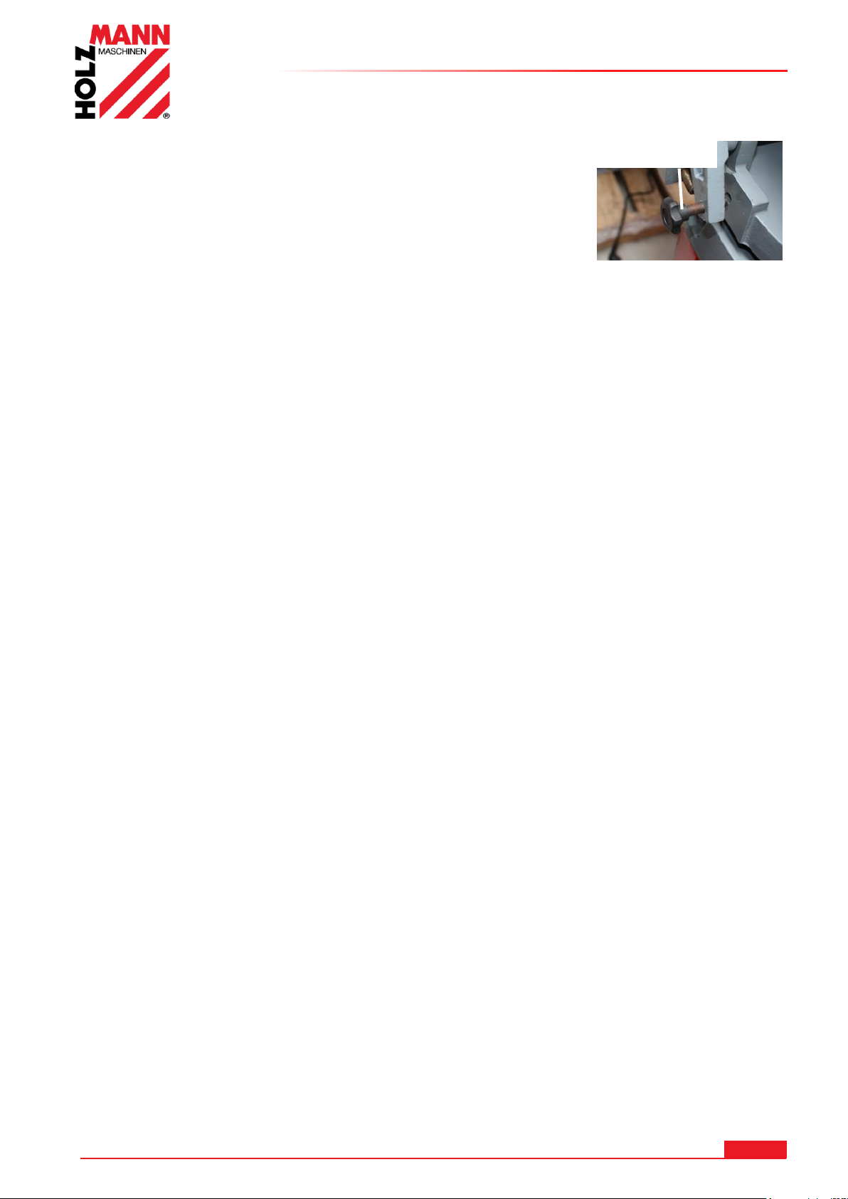
Fixierbolzen
8.4.10 Sägen
Schalten Sie die Maschine mit dem EIN / AUS Schalter (9) ein.
Entfernen Sie den Fixierbolzen.
Durch den automatischen Vorschub bewegt sich der Sägearm
selbstständig nach unten.
Üben Sie keinen Druck aus.
Die Säge schaltet sich nach Durchschneiden des Materials
automatisch durch Auslösung des AUS-Schaltknopf aus.
Ziehen Sie den Sägearm in die Höhe und stecken Sie den Fixierbolzen wieder in der Bohrung.
DIE ZAHNUNG DES SÄGEBANDES SOLLTE DEM ZU SCHNEIDENDEN MATERIAL
EBENFALLS ANGEPASST WERDEN:
1. Je dünner / schmaler das Werkstück, desto höhere Zahnung
2. Grundregel: es sollten zu jedem Zeitpunkt mindestens 3 Zähne im Material arbeiten
ACHTUNG: Wenn die Metallbandsäge längere Zeit nicht benutzt wird, entspannen Sie das
Sägeband mit dem Einstellknopf für die Sägebandspannung (10)
HOLZMANN MASCHINEN GmbH www.holzmann-maschinen.at 29
BS115 / BS128HDR
Page 30
WARTUNG
AC HT UN G
Vor Wartungsarbeiten Maschine ausschalten und den
Netzstecker ziehen!
Sachschäden und schwere Verletzungen durch
unbeabsichtigtes Einschalten der Maschine werden so
vermieden!
HI NW EI S
Nur ein regelmäßig gewartetes und gut gepflegtes Gerät kann ein zufrieden stellendes
Hilfsmittel sein. Wartungs- und Pflegemängel können zu unvorhersehbaren Unfällen und
Verletzungen führen.
Reparaturen die spezielle Fachkenntnisse erfordern, sollten nur von autorisierten Service
Centern durchgeführt werden.
Unsachgemäßer Eingriff kann das Gerät beschädigen oder Ihre Sicherheit gefährden.
9 WARTUNG
Die Maschine ist wartungsarm und enthält nur wenig Teile, die der Bediener einer Instandhaltung
unterziehen muss.
Störungen oder Defekte, die die Sicherheit der Maschine beeinträchtigen können, umgehend
beseitigen lassen.
Prüfen Sie regelmäßig, ob die Warn- und Sicherheitshinweise an der Maschine vorhanden und in
einwandfrei leserlichem Zustand sind.
Prüfen Sie vor jedem Betrieb den einwandfreien Zustand der Sicherheitseinrichtungen!
Bei Lagerung der Maschine darf diese nicht in einem feuchten Raum aufbewahrt werden und muss
gegen den Einfluss von Witterungsbedingungen geschützt werden.
Vor der ersten Inbetriebnahme alle beweglichen Verbindungsteile mit einer dünnen Schicht
Schmieröl oder Schmierfett einschmieren.
9.1 Instandhaltung und Wartungsplan
Nach jeder Inbetriebnahme:
Sägearm in oberste Stellung bringen und fixieren.
Sägeband entspannen.
Reinigen Sie die Maschine vollständig.
Gleitflächen des Schraubstockes, sowie die Sägebandführung mit leichtem Maschinenöl
schmieren.
Nach 50 Betriebsstunden
Alle beweglichen Verbindungsteile (falls erforderlich vorher mit einer Bürste von Spänen und
Staub reinigen) mit einer dünnen Schicht Schmieröl oder Schmierfett einschmieren
BS115 / BS128HDR
HOLZMANN MASCHINEN GmbH www.holzmann-maschinen.at 30
Page 31
9.2 Sägebandwechsel
Die Metallbandsäge in die vertikale Position bringen und die
Sägebandabdeckung öffnen.
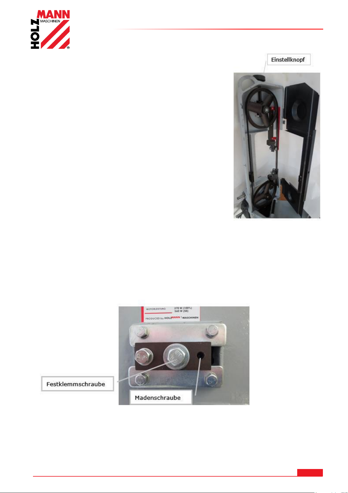
Das Sägeband mit dem Einstellknauf (10) lockern.
Das Sägebandschutzblech an der Sägebandführung oben
abschrauben.
Ziehen Sie nun das alte Sägeband von den Laufrädern ab.
ACHTUNG! Verletzungsgefahr! Tragen Sie Arbeitshandschuhe.
Das neue Sägeband zuerst in die Sägebandführungen einlegen
und anschließend auf die Laufräder auflegen.
ACHTUNG: Die richtige Laufrichtung der Zahnung beachten. -
siehe Abbildung vorne links am Sägearm- Anschließend auf die
Laufräder legen.
Das Sägeband mit dem Einstellknopf (10) Spannung (1mm
Test) einstellen.
Nach einem kurzen Testlauf die Spannung und den Bandlauf /
Sturz nachprüfen und gegebenenfalls nachspannen und
einstellen.
Das Sägebandschutzblech wieder anschrauben.
Beide Sägebandabdeckungen wieder anschrauben
WARTUNG
9.3 Bandlauf / Sturz einstellen
Das Laufrad ist werksseitig auf das Antriebsrad ausgerichtet. Sollte jedoch – v.a. nach Wechsel des Sägeband nicht gerade bzw. vom Laufrad ablaufen, könnte ein Nachstellen nötig sein.
Der Bandlauf / Sturz kann nachjustiert werden.
Die Festklemmschraube leicht lockern.
Mit der Madenschraube kann der Bandlauf nachjustiert werden.
Die Festklemmschraube wieder festziehen.
HOLZMANN MASCHINEN GmbH www.holzmann-maschinen.at 31
BS115 / BS128HDR
Page 32
WARTUNG
HI NW EI S
Der Einsatz von Lösungsmitteln, aggressiven Chemikalien oder
Scheuermitteln führt zu Sachschäden an der Maschine!
Daher gilt: Bei der Reinigung nur Wasser und wenn notwendig milde
Reinigungsmittel verwenden!
9.4 Schmierung
Kugellager müssen nicht geschmiert werden.
Schmieren sie die Gewindestange der Spannbacke nach Bedarf
Bedecken Sie alle nicht lackierten Flächen regelmäßig mit einer dünnen Schicht leichtem
Maschinenöl.
Das Getriebe läuft in einem Ölbad und bedarf ca. 1-mal jährlich eines Ölwechsels:
Bringen Sie dazu den Sägearm in horizontale Position
Lösen Sie die vier Schrauben von der Getriebeabdeckung und entfernen Sie die Abdeckung.
Legen Sie einen Auffangbehälter unter das Getriebegehäuse.
Heben Sie nun den Sägearm sodass das Öl herausfließt.
Reinigen Sie das Getriebegehäuse von gröberen Altölresten, füllen Sie neues GETRIEBEÖL ein,
montieren Sie die Abdeckung wieder ordnungsgemäß.
Entsorgen Sie das Altöl umweltgerecht.
9.5 Reinigung
Nach jeder Inbetriebnahme muss die Maschine und alle ihre Teile gründlich gereinigt werden.
Befreien Sie die Maschine regelmäßig nach der Arbeit von Spänen und Bohrmehl.
Blanke Flächen der Maschine gegen Korrosion mit handelsüblichen Mitteln imprägnieren.
9.6 Entsorgung
Entsorgen Sie Ihre Maschine nicht im Restmüll. Kontaktieren Sie Ihre lokalen
Behörden für Informationen bzgl. der verfügbaren Entsorgungsmöglichkeiten. Wenn
Sie bei Ihrem Fachhändler eine neue Maschine oder gleichwertiges Gerät kaufen, ist
dieser verpflichtet, Ihre alte fachgerecht zu entsorgen.
HOLZMANN MASCHINEN GmbH www.holzmann-maschinen.at 32
BS115 / BS128HDR
Page 33
FEHLERBEHEBUNG
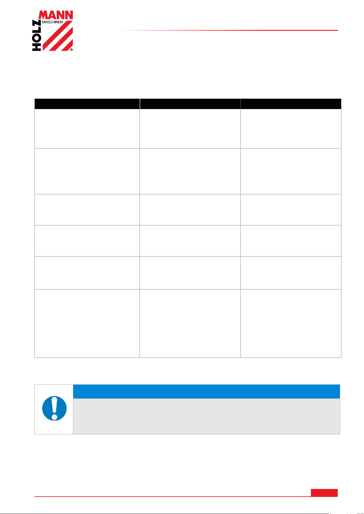
Fehler
Mögliche Ursache
Behebung
Maschine startet nicht
Maschine ist nicht
angeschlossen
Sicherung oder Schütz kaputt
Kabel beschädigt
Alle el. Steckverbindungen
überprüfen
Sicherung wechseln,
Schütz aktivieren
Kabel erneuern
Sägeband kommt nicht auf
Geschwindigkeit
Verlängerungskabel zu lang
Motor nicht für bestehende
Spannung geeignet
schwaches Stromnetz
Austausch auf passendes
Verlängerungskabel
siehe Schaltdosenabdeckung
für korrekte Verdrahtung
Kontaktieren Sie den
Elektro-Fachmann
Motor erhitzt sich sehr schnell
Motor erhält auf einer oder
mehreren Phasen nicht
genügend Strom
Kontaktieren Sie den
Elektro-Fachmann.
Kein Garantiefall. Fehler
Netzseitig.
Band läuft in die verkehrte
Richtung
Phasen vertauscht
Kontaktieren Sie den
Elektro-Fachmann.
Kein Garantiefall. Fehler
Netzseitig.
Maschine vibriert stark
Steht auf unebenen Boden
Motorbefestigung ist lose
Neu einrichten
Befestigungsschrauben
anziehen
Schlechte Schnitte
Zu große Senkgeschwindigkeit
Ungeeignetes Sägeband
Stumpfes Sägeband
Sägeband ist locker
Sägebandführung ist verstellt
Wählen Sie eine langsamere
Senkgeschwindigkeit
Verwenden Sie für
Hartmetalle ein BIMetallsägeband
Wechseln Sie das Sägeband
Spannen Sie das Sägeband
Stellen Sie die
Sägebandführung nach
HI NW EI S
Sollten sie sich bei notwendigen Reparaturen nicht in der Lage fühlen
diese ordnungsgemäß zu verrichten, oder besitzen sie die
vorgeschriebene Ausbildung dafür nicht, ziehen sie immer eine
Fachwerkstätte zum Beheben des Problems hinzu.
10 FEHLERBEHEBUNG
BEVOR SIE DIE ARBEIT ZUR BESEITIGUNG VON DEFEKTEN BEGINNEN, TRENNEN SIE
DIE MASCHINE VON DER STROMVERSORGUNG.
VIELE POTENTIELLE FEHLERQUELLEN LASSEN SICH BEI FACHGEMÄSSEM ANSCHLUSS
AN DAS SPEISESTROMNETZ IM VORHINEIN AUSSCHLIESSEN.
HOLZMANN MASCHINEN GmbH www.holzmann-maschinen.at 33
BS115 / BS128HDR
Page 34
PREFACE (EN)
HOLZMANN MASCHINEN GmbH
4170 Haslach, Marktplatz 4
AUSTRIA
Tel +43 7289 71562 - 0
Fax +43 7289 71562 – 4
11 PREFACE (EN)
Dear Customer!
This manual contains information and important instructions for the installation and correct use of
the metal band saw BS 115 / BS 128HDR.
Following the usual commercial name of the machine (see cover) is substituted in this manual with
the name "machine".
This manual is part of the product and shall not be stored separately from the product. Save it for
later reference and if you let other people use the product, add this instruction manual to the
product.
Please read and obey the security instructions!
Before first use read this manual carefully. It eases the correct use of the product and
prevents misunderstanding and damages of product and the user’s health.
Due to constant advancements in product design, construction pictures and content may diverse
slightly. However, if you discover any errors, inform us please.
Technical specifications are subject to changes!
Please check the product contents immediately after receipt for any eventual transport
damage or missing parts.
Claims from transport damage or missing parts must be placed immediately after initial
product receipt and unpacking before putting the product into operation.
Please understand that later claims cannot be accepted anymore.
Copyright
© 2017
This document is protected by international copyright law. Any unauthorized duplication,
translation or use of pictures, illustrations or text of this manual will be pursued by law.
Court of jurisdiction is the Landesgericht Linz or the competent court for 4170 Haslach, Austria!
Customer service contact
HOLZMANN MASCHINEN GmbH www.holzmann-maschinen.at 34
BS115 / BS128HDR
Page 35
12 TECHNIC
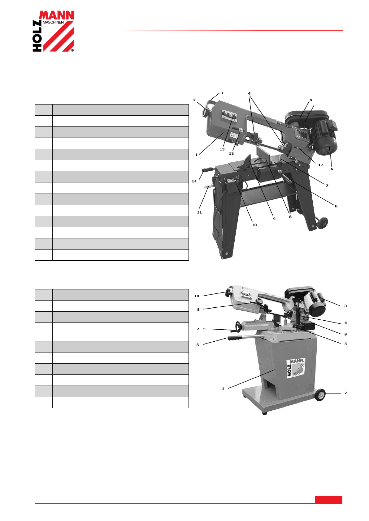
1
Saw arm
2
Blade tension adjustment knob
3
Headband for the saw arm
4
Adjustable bandsaw blade guide
5
Belt cover
6
Motor
7
Cutting depth limit screw
8
Holding jaw angle adjustment
9
Jaw angle adjustable
10
ON-OFF switch
11
Charging handle for clamping jaw
12
Fixing screw bandsaw blade guide
13
Setting caster / camber
14
Setting the feed suspension
1
Machine main body
2
Wheel
3
Motor
4
Hydraulic clamping cylinder with
adjustment for feed
5
Clamping screw for miter
6
Lifting handle
7
Handwheel for vice
8
Clamping screw for saw belt
9
ON-OFF switch
10
Adjustment of band tightening
12.1 Components
12.1.1 BS115
TECHNIC
12.1.2 BS128HDR
HOLZMANN MASCHINEN GmbH www.holzmann-maschinen.at 35
BS115 / BS128HDR
Page 36
12.2 Technical data BS115
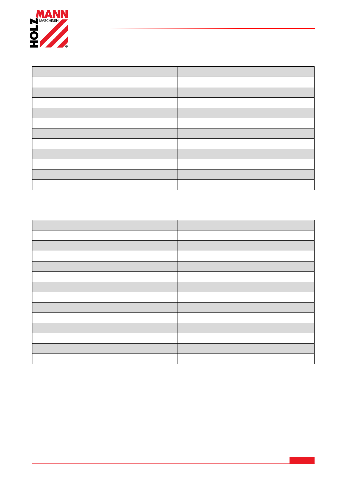
Voltage
230 / 400 V
Motor power
550 W
Cutting speeds
20-29-50 m/min
Blade dimension
1638x0,6x12,5 mm
max. Ø round profile at 90°
110 mm
max. Ø round profile at 45
75 mm
max. HxW hexagonal tube at 90°
110x140 mm
max. HxW hexagonal tube at 45°
110x75 mm
Dimensions L x W x H
970x395x945 mm
Weight
56 kg
Sound power level LWA
76 dB(A)
Protection mode
IP 20
Voltage
230 / 400 V
Motor power
550 W
Cutting speeds
23 – 34 – 54 m/min
Blade dimension
1640 x 13 x 0,6 mm
max. Ø round profile at 90°
125 mm
max. Ø round profile at 45°
95 mm
max. Ø round profile at 60°
50 mm
max. HxW hexagonal tube at 90°
100 x 150 mm
max. HxW hexagonal tube at 45°
95 x 76 mm
max. HxW hexagonal tube at 60°
50 x 56 mm
Dimensions L x W x H
1000 x 550 x1100 mm
Weight
76 kg
Sound power level LWA
76 dB(A)
Protection mode
IP20
TECHNIC
12.3 Technical data BS128HDR
HOLZMANN MASCHINEN GmbH www.holzmann-maschinen.at 36
BS115 / BS128HDR
Page 37
SAFETY
WA RN IN G
Use only blades allowable for this machine
Never use damaged blades!
Never use the machine with defective or without mounted guards
The removal or modification of the safety components may result in
damage to equipment and serious injury!
The workpiece must be always clamped in the machine vice during cutting
To remove sawdust and chippings from the machine when running is
strictly prohibited!
HIGHEST RISK OF INJURY!
13 SAFETY
13.1 Intended use
The machine must only be used for its intended purpose! Any other use is deemed to be a case of
misuse.
To use the machine properly you must also observe and follow all safety regulations, the assembly
instructions, operating and maintenance instructions lay down in this manual.
All people who use and service the machine have to be acquainted with this manual and must be
informed about the machine's potential hazards.
It is also imperative to observe the accident prevention regulations in force in your area.
The same applies for the general rules of occupational health and safety.
The machine is used for:
To cut metal, cast iron and plastic materials
Any manipulation of the machine or its parts is a misuse, in this case HOLZMANN-
MASCHINEN and its sales partners cannot be made liable for ANY direct or indirect
damage.
13.2 Prohibited use
The operation of the machine outside the stated technical limits described in this manual is
forbidden.
The machine shall not be operated in areas exposed to increased fire or explosion hazard.
The use of the machine not being suitable for the use of the machine and not being certified is
forbidden.
The use of the machine not according with the required dimensions is forbidden.
Any manipulation of the machine and parts is forbidden.
The use of the machine for any purposes other than described in this user-manual is forbidden.
The unattended operation on the machine during the working process is forbidden
It is not allowed to leave the immediate work area during the work is being performed!
13.3 Security instructions
Missing or non-readable security stickers have to be replaced immediately!
The locally applicable laws and regulations may specify the minimum age of the operator
and limit the use of this machine!
To avoid malfunction, machine defects and injuries, read the following security instructions!
HOLZMANN MASCHINEN GmbH www.holzmann-maschinen.at 37
BS115 / BS128HDR
Page 38
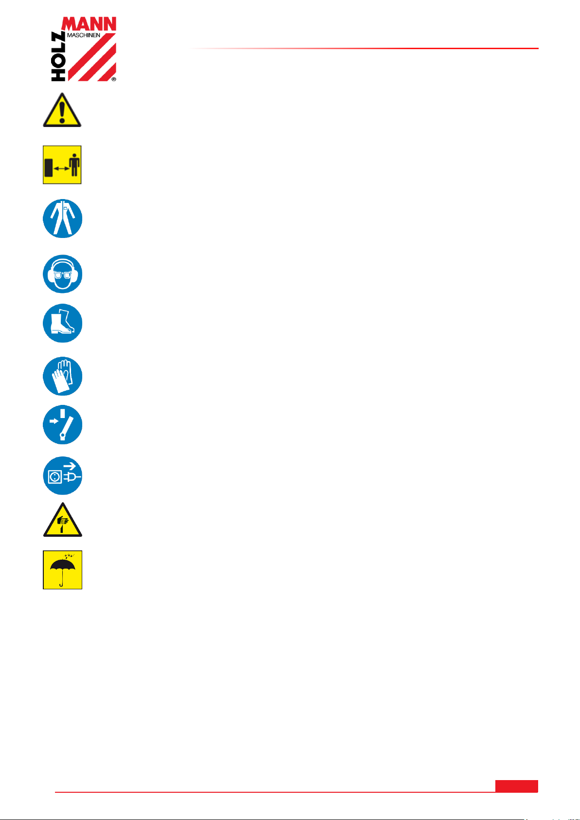
SAFETY
Keep your work area dry and tidy! An untidy work area may cause accidents. Avoid
slippery floor!
Make sure the work area is lighted sufficiently!
Work only in a well ventilated area!
Do not overload the machine!
Provide good stability and keep balance all times.
Keep away from the running blade!
Always stay focused when working. Reduce distortion sources in your working
environment. The operation of the machine when being tired, as well as under the
influence of alcohol, drugs or concentration influencing medicaments is forbidden!
Only one person shall operate the machine
The machine must be operated only by trained persons (knowledge and
understanding of this manual), which have no limitations of motor skills compared
with conventional workers.
Do not allow other people, particularly children, to touch the machine or the cable.
Keep them away from your work area!
Make sure there is nobody present in the dangerous area. The minimum safety
distance is 2m
Wear suitable work clothes! Do not wear loose clothing or jewelry as they might be
caught and cause severe accidents!
Wear a hair net if you have long hair
Loose objects can become entangled and cause serious injuries!
Use personal safety equipment: ear protectors, safety goggles, safety shoes S1,
work wear, safety gloves (EN 388, class 3111) when working with or on the
machine!
Never leave the machine running unattended! Before leaving the working area
switch the machine off and wait until the machine stops!
Always disconnect the machine prior to any actions performed at the machine!
Avoid unintentional starting
Do not use the machine with damaged switch
The plug of an electrical tool must strictly correspond to the socket. Do not use any
adapters together with earthed electric tools
Each time you work with an electrically operated machine, caution is advised! There
is a risk of electric shock, fire, cutting injury;
Protect the machine from dampness (causing a short circuit)
Use power tools and machines never in the vicinity of flammable liquids and gases
(danger of explosion)
Check the cable regularly for damage
Do not use the cable to carry the machine or to fix the work piece
Protect the cable from heat, oil and sharp edges
Avoid body contact with earthed components
Serious injuries caused by sharp edges on the hand are possible.
13.4 Remaining risk factors
Even if the machine is used as required it is still impossible to eliminate certain residual risk
factors totally. The following hazards may arise in connection with the machine´s construction
and design:
• Risk of injury to the hands / fingers by the blade during operation.
• Risk of injury due to sharp edges of the workpiece.
• Risk of injury due to contacting with live electrical components.
• Risk of injury due to breakage or being thrown out of the saw blade or portions thereof, at
overloading and incorrect direction of the saw blade..
• Risk of injury to the hearing by prolonged labor without hearing protection
• Risk of injury to the eye by flying debris, even with goggles.
HOLZMANN MASCHINEN GmbH www.holzmann-maschinen.at 38
BS115 / BS128HDR
Page 39
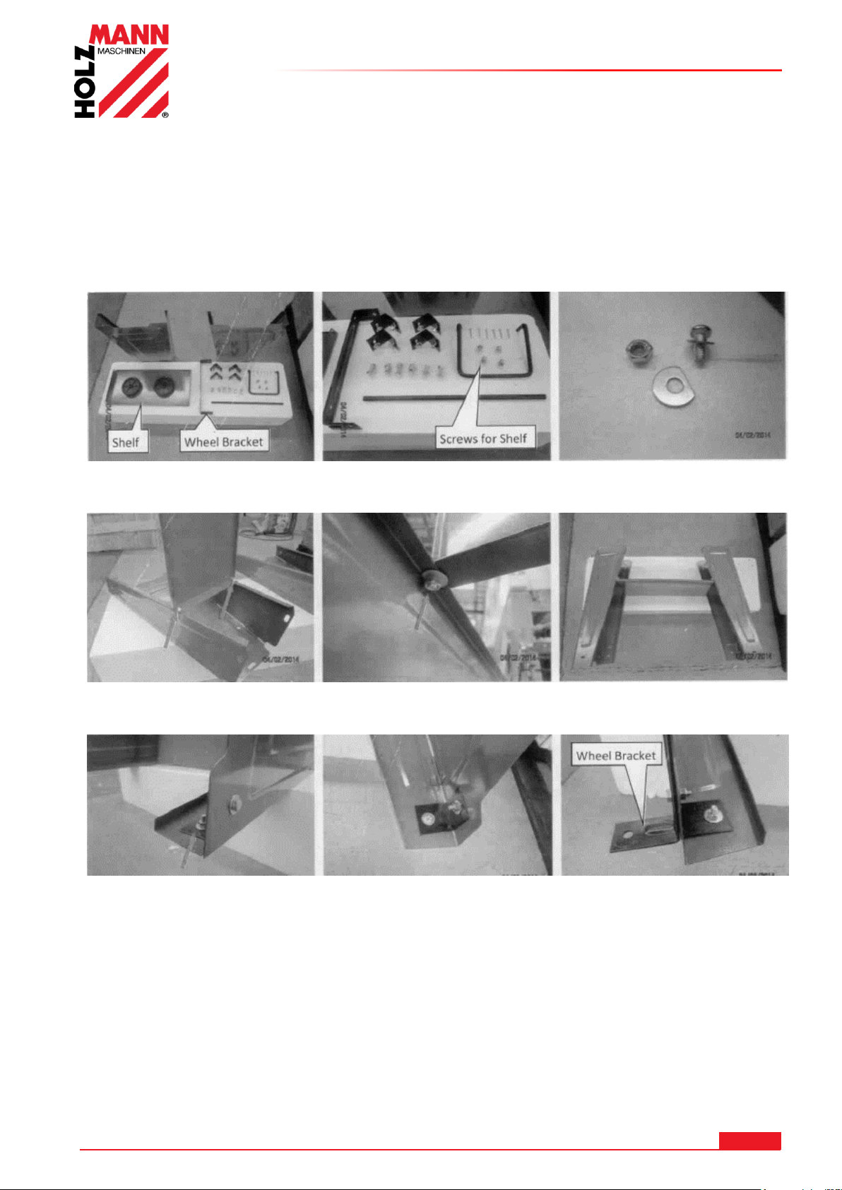
ASSEMBLY
1. Delivery content Screws, washers n unts
3. Lay a leg on the flor and fix one end of the shelf as shown 4. Fiy a leg on the other side
5. Fit the corner brackets inside the leg as shown 6. Fit the corner legs with the
wheel brackets to the other
leg
14 ASSEMBLY
Please check the product contents immediately after receipt for any eventual transport damage or
missing parts. Claims from transport damage or missing parts must be placed immediately after
initial machine receipt and unpacking before putting the machine into operation. Please
understand that later claims cannot be accepted anymore.
14.1 BS115
HOLZMANN MASCHINEN GmbH www.holzmann-maschinen.at 39
BS115 / BS128HDR
Page 40
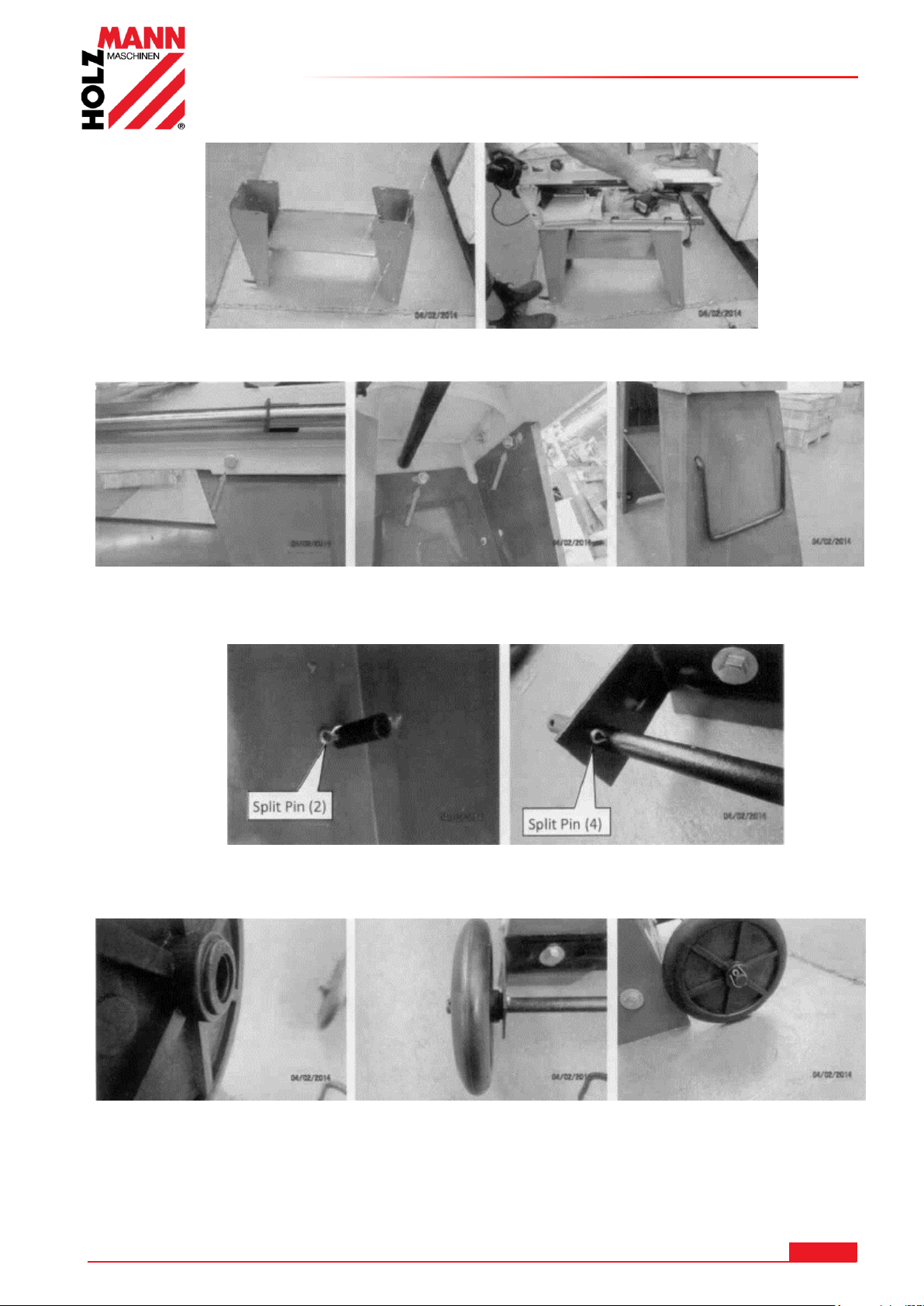
ASSEMBLY
Place the saw carefully on the top of the stand with 2 people ensuring the top of the stand fits
inside the saw base. Make sure that the motor is at the end with the wheel brackets.
8. Bolt the saw base to the legs as shown. 9. Insert the handle
10. Fit the handle inside with a splint pin. 11. Insert the axle and fit both ends with a
splint pin.
12. Mount the wheels and fit them with a splint pin. 13.Also the second wheel
HOLZMANN MASCHINEN GmbH www.holzmann-maschinen.at 40
BS115 / BS128HDR
Page 41
ASSEMBLY
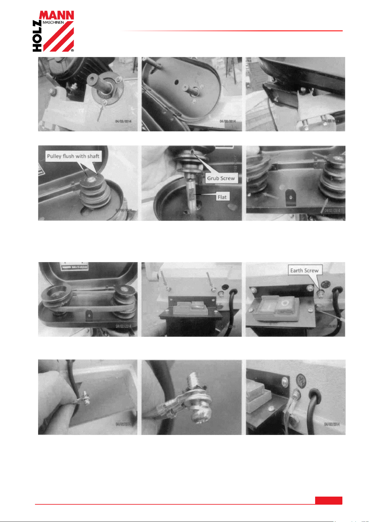
14. Using 2 screws and 1 bolt fit the belt guard as shown.
15. Fit the motor pulley. Make sure that the key is on the right place and tighten the grub screw.
Fit the driven pulley as shown and make sure both pulleys are the same distance from the belt
guart or the top faces of both pulleys are level. Tighten the grub screw
17. Insert the drive belt . 18. Fit thr switch box.
Work should be exclusively carried out by qualified personnel!
19. Connect the earth wires as shown.
HOLZMANN MASCHINEN GmbH www.holzmann-maschinen.at 41
BS115 / BS128HDR
Page 42
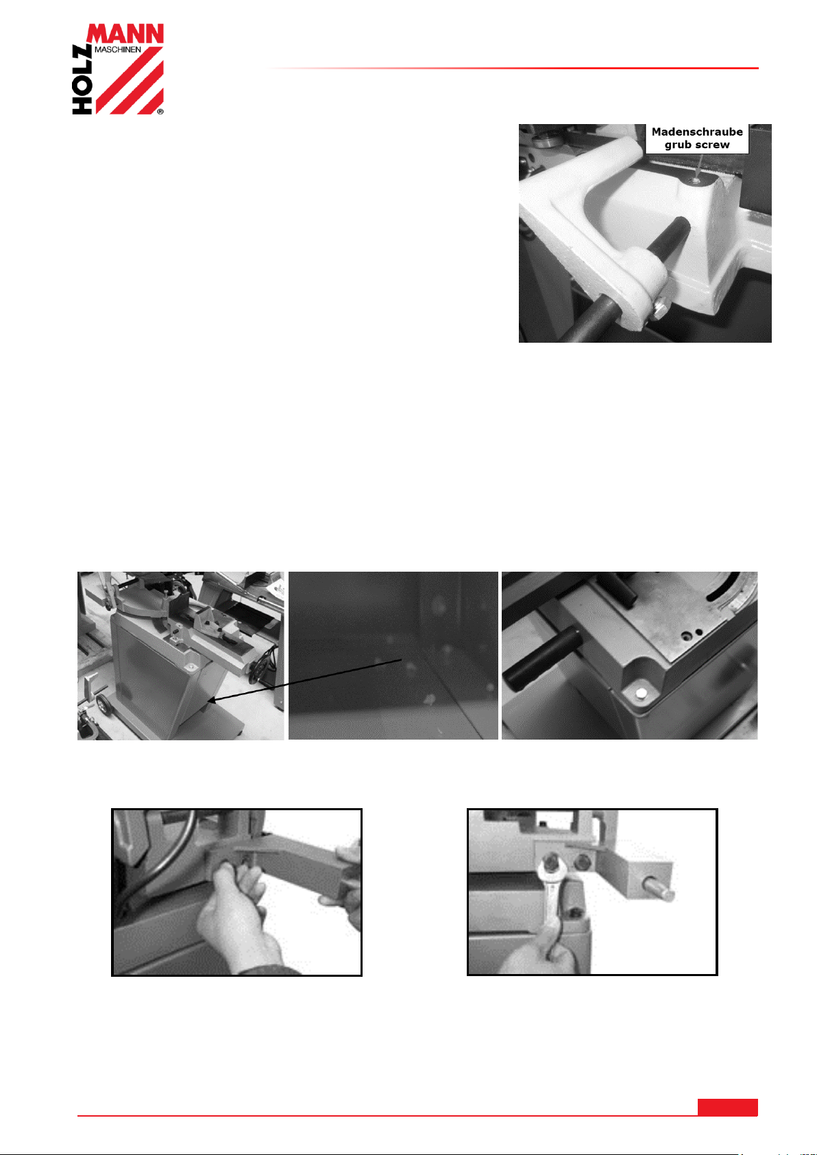
20. Install the stop.
Slide the guide bar in the socket and tighten the set screw.
Install the adapter over the leadership of round steel
14.2 BS128HDR
The BS 128HDR assembled ready in principle.
You only need to assemble the undercarriage.
To mount the first wheels.
After that, the base must be assembled (fitting in with the chassis).
In the end, the band saw is placed on the base and fastened with screws.
ASSEMBLY
Screw the suspension
The spring bracket is screwed as shown on the console
HOLZMANN MASCHINEN GmbH www.holzmann-maschinen.at 42
BS115 / BS128HDR
Page 43
ASSEMBLY
WA RN IN G
The lifting and transportation of the machine must only be carried out by
qualified staff and must be carried out with appropriate equipment.
AT TE NT IO N
When working with non-grounded machines:
Severe injury or even death may arise though electrocution!
Therefore: The machine must be operated at a grounded power socket
14.3 Workplace requirements
The workplace has to fulfill the requirements.
The ground has to be even, in level and hard. It must be suitable at least to weight it with double
weight per square meter than the machines net weight.
The chosen workplace must have access to a suitable electric supply net hat complies with the
machines requirements.
14.4 Transport
The machine can be transported in package with a forklift.
The machine is very heavy. The machine shall be lifted from crate with a suitable lifting device only
that is certified to be able to carry the machines load.
Note that lifting equipment used (crane, forklift, sling, etc.) must be in perfect condition.
To maneuver the machine in the packaging can also a pallet jack or a forklift be used.
Uncoated metal machine parts have been insulated with a greasy layer to inhibit corrosion.
This layer has to be removed. You can use standard solvents that do not damage the machine
surface.
14.5 Power supply
The connection of the machine to the electric power supply and the following checks have to be
carried out by a respectively trained electrician only.
1. The electronic connection of the machine is designated for operation with a grounded power
socket!
2. The mains supply must be secured with 16A:
3. If the connector plug doesn’t fit or if it is defect, only qualified electricians may modify or
re-new it!
4. The grounding wire should be held in green-yellow.
5. A damaged cable has to be exchanged immediately!
6. Check, whether the feeding voltage and the Hz comply to the required values of the
machine. A deviation of feeding voltage of ±5% is allowed (e.g.: a machine with working
voltage of 380V can work within a voltage bandwidth of 370 till 400V.
7. After connecting, check the right running direction!
8. Make sure that a possible extension cord is in good condition and suitable for the
transmission of power. An undersized cord reduces the transmission of power and heats up.
9. A damaged cable must be replaced immediately
HOLZMANN MASCHINEN GmbH www.holzmann-maschinen.at 43
BS115 / BS128HDR
Page 44
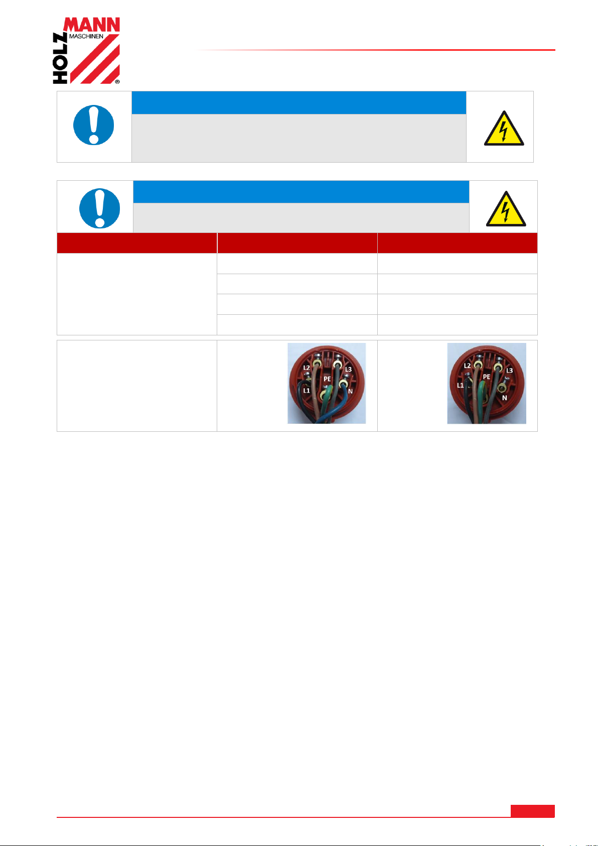
ASSEMBLY
NO TI CE
Operation is only allowed with safety switch against stray
current (RCD max. stray current of 30mA)
NO TI CE
Use only permitted extension cable with cross-section
the one in the following table declared.
Voltage
Extension
Cross-section
220 V-240 V
50 Hz
<27 m
1,5 mm
2
<44 m
2,5 mm
2
<70 m
4,0 mm
2
<105 m
6,0 mm
2
Plug 400V:
5-wire:
with
N-conductor
4-wire:
without
N-conductor
HOLZMANN MASCHINEN GmbH www.holzmann-maschinen.at 44
BS115 / BS128HDR
Page 45
OPERATION
WA RN ING
Perform all machine settings with the machine being
disconnected from the power supply!
NO TI CE
Checks to carry out before each workshift:
General technical condition of the machine
Safety equipment available and in working order
Check sawband for wear and replace if necessary
Moving parts are not blocked
All the components for correct fit and function, especially the screws
on the blade guard and lever control!
All the tools for service / maintenance from the machine.
Set the blade guard as close as possible to the workpiece.
Splash guard
Checks to carry out before each cut:
Angle set correctly?
Vice adequately fixed?
Make sure that the material to be processed is fixed properly in the
vice.
Ensure that the coolant circulates properly.
Running direction of saw blade.
Never switch the machine on while pressing the blade against
the material!
Wait until the sawband has reached full speed – then
performing the cut!
Always support long overhanging workpieces additionally
15 OPERATION
Device to be operated in a perfect state only. Inspect the device visually every time it is to be
used. Check in particular the safety equipment, electrical controls, electric cables and screwed
connection for damage and if tightened properly. Replace any damaged parts before operating
the device..
15.1 Operation instructions
HOLZMANN MASCHINEN GmbH www.holzmann-maschinen.at 45
BS115 / BS128HDR
Page 46
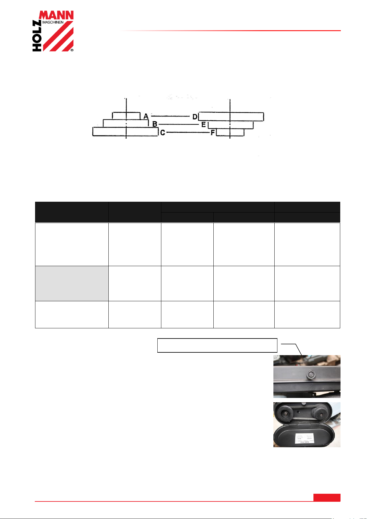
OPERATION
Material
speed
(m/min)
Belt position
Motor pulley
Drive pulley
Saw band
Stainless Steel
Stainless Steel ®
Tool steel
Alloy steel
Bearing bronze
20 A D
Bi-Metal
Structural steel
iron
mild steel
Thomas steel
29 B E
Bi-Metal
Brass
Aluminium
Similar materials
50 C F
HSS
Motor pulley Drive pulley
Knob screw or tapping screw
15.2 BS115
15.2.1 Select the saw blade speed
The saw blade is driven via a belt drive. Adjust the saw blade speed at the material to be cut.
Select the feed according to the following table.
Unscrew the screw on the lid and the lid up.
Loosen the two screws on the motor mount.
The belt is now positioned to the corresponding position of the table
(also in the lid visible).
Tighten the two screws on the motor bracket and close the cover and
screw.
HOLZMANN MASCHINEN GmbH www.holzmann-maschinen.at 46
BS115 / BS128HDR
Page 47
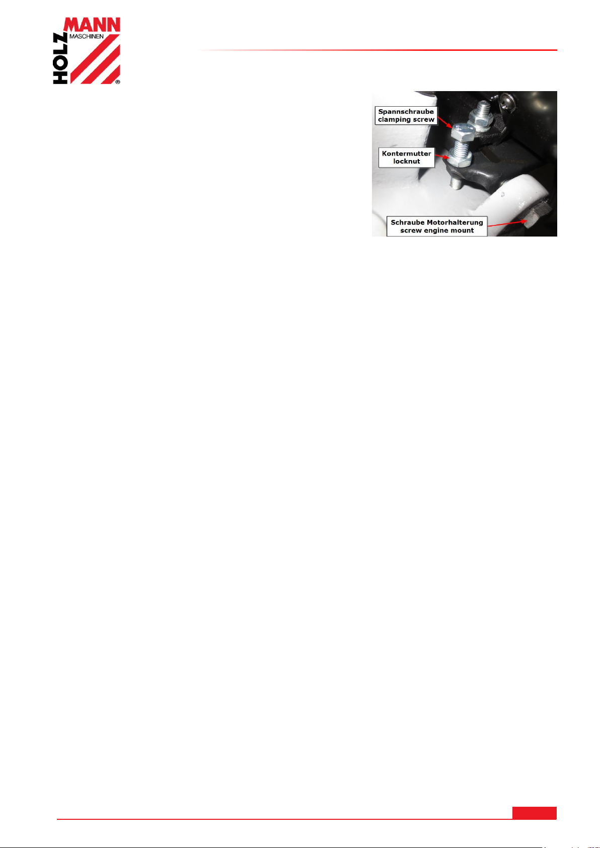
15.2.2 Adjustment of belt tension
The two screws on the motor bracket are loosened
slightly.
Loosen the lock nut and adjust the belt with the tension
screw to about 2-5mm game.
Tighten the locknut.
Tighten the screws on both sides of the engine mount.
THE TEETH OF THE SAW BLADE SHOULD THE
OVERLAPPING MATERIAL TO ALSO BE ADAPTED:
1. The thinner / narrow the workpiece, the higher the toothing.
2. Basic rule: it should at all times at least 3 teeth own material
15.2.3 Adjustment of the miter angle
Loosen the fastening of the holding jaw (8)
Set the holding jaw to the desired angle.
OPERATION
15.2.4 Clamping the workpiece
Create the workpiece at the holding jaw and tighten it with the clamp (9). The clamping jaw can
be adjusted according to the crank (11).
15.2.5 Setting the saw band tension
Check the blade tension: Never use a thumb in the middle of the saw band light pressure
- it should be about 1mm -.
If the saw blade is not tightened correctly, you must readjust the tension with the adjustment
knob (2).
15.2.6 Setting the feed
Suspension with the handle of the feed (14) can be tightened by turning to the right, the spring
and the feed can be reduced. Turning to the left of the feed is increased.
HOLZMANN MASCHINEN GmbH www.holzmann-maschinen.at 47
BS115 / BS128HDR
Page 48
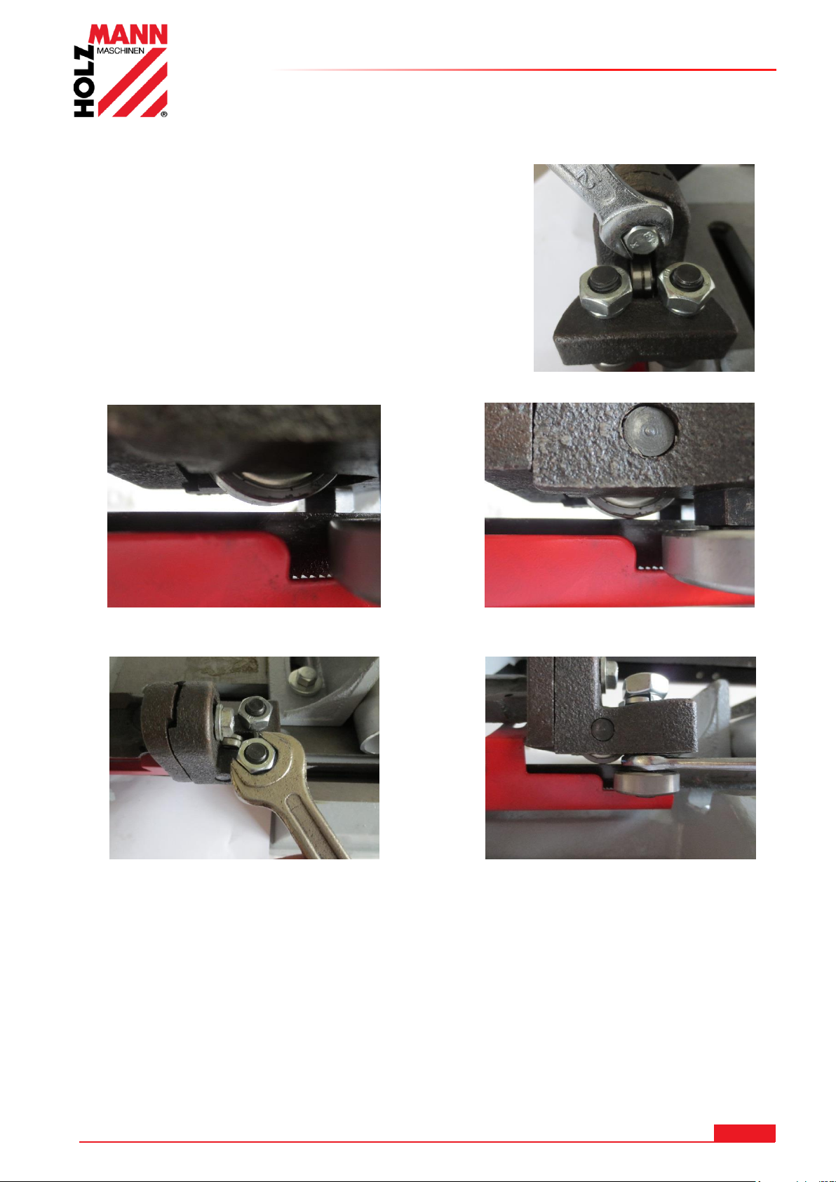
15.2.7 Adjusting the vertical bandsaw blade guide for clippings
Slightly loosen the left bandsaw blade
guide with the screw for fixation.
The tolerance by lowering the band saw blade guide leveling on bearing roll on the band saw
blade to zero.
Slightly loosen the nuts on either side guide
rollers with a wrench SW17.
With a wrench SW 12 is with the help of the
eccentric bearing roller according to externally or
internally displaced.
Repeat on both sides of the process until no play
between the bearing rollers.
The bandsaw blade should be centered on the
upper bearing role.
CAUTION: The two lower side rollers do not
clamp!
After both bearing rollers are adjusted free of play, the two nuts tighten up the leadership
roles.
OPERATION
HOLZMANN MASCHINEN GmbH www.holzmann-maschinen.at 48
BS115 / BS128HDR
Page 49
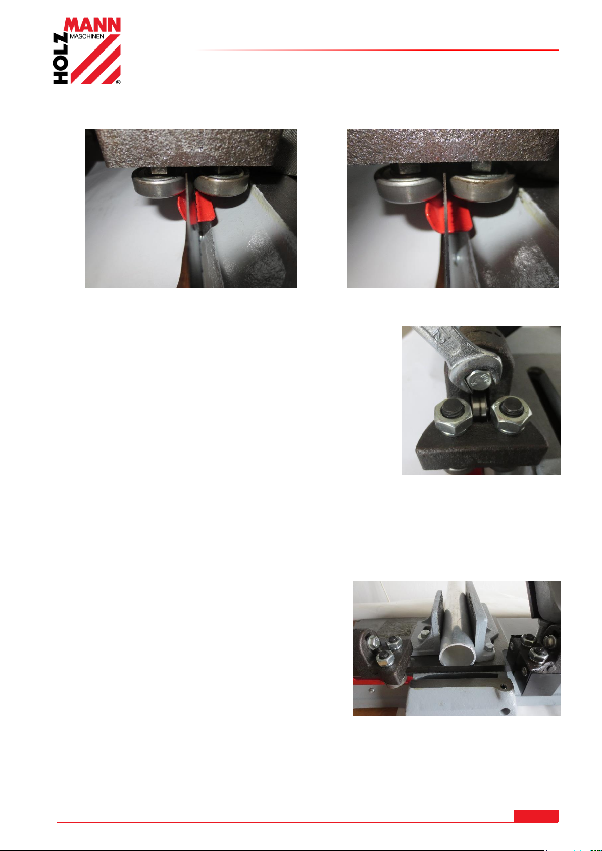
OPERATION
Example of a perfect adjustment of the bandsaw blade guide:
The bandsaw blade has too much play and is
therefore still cant between the lateral bearing
rollers.
The saw blade is completely vertically without
any play between the lateral bearing rollers.
CAUTION:
Before tightening the bandsaw blade guide examine
whether the saw band is below set perfectly vertical and
readjust the bandsaw blade guide according vertically.
The bandsaw blade guide with the screw for fixing
tighten.
NOTE: Check the 90 ° bandsaw blade guide with an angle gauge or with a rectangular
workpiece.
Repeat this process on the right if the saw band saw blade guiding is not performed exactly
vertical.
NOTE: The bandsaw blade guide slide (left / right) as close as possible to the workpiece.
By loosening the fixing nuts (12), the blade guides
can be moved.
CAUTION: Bevel cuts are resulting from not exactly vertical set saw blade guides and
too much play between the lateral bearing rollers!
HOLZMANN MASCHINEN GmbH www.holzmann-maschinen.at 49
BS115 / BS128HDR
Page 50
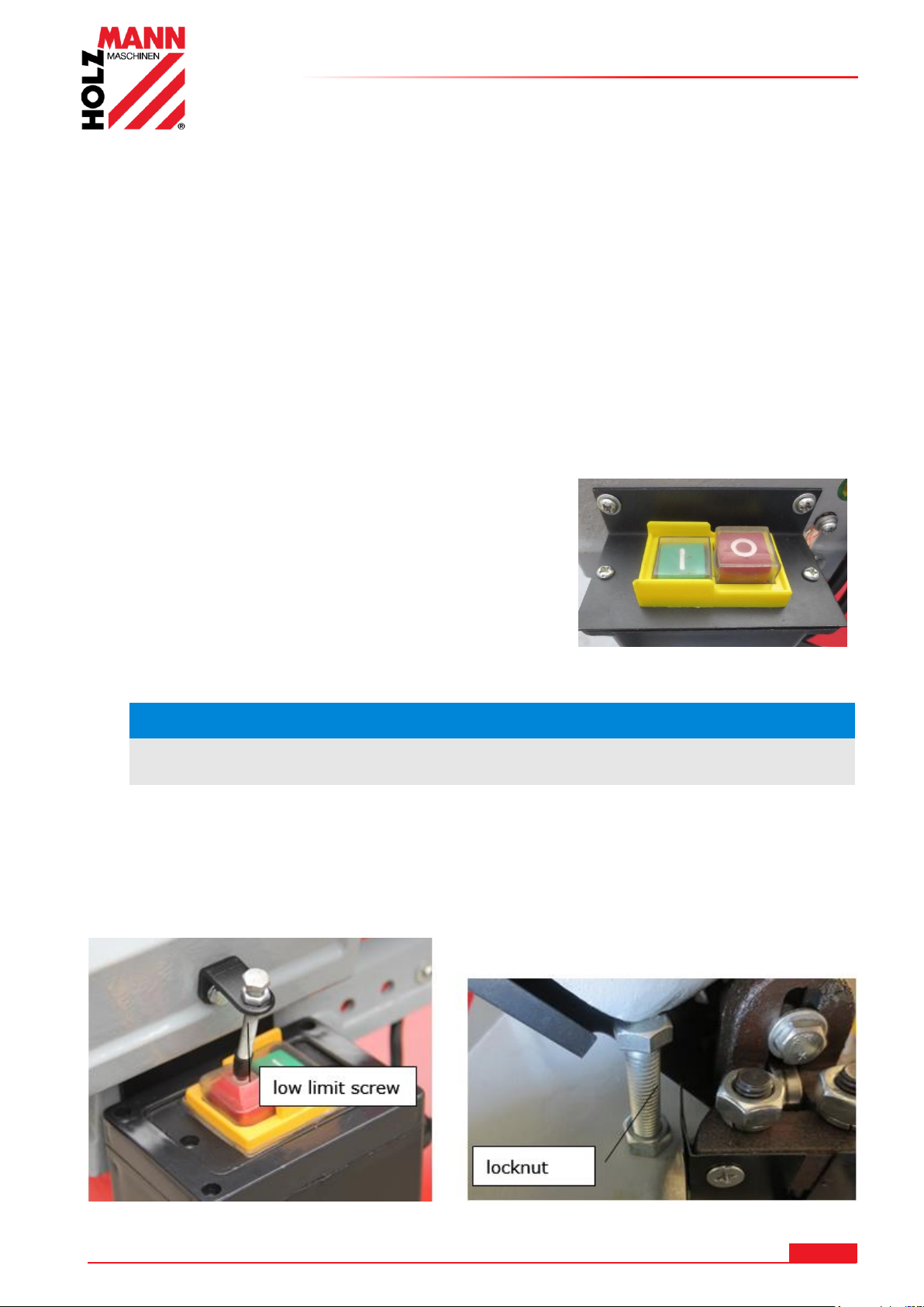
OPERATION
NO TE
Allow the engine to start full before starting to Be Cut.
15.3 Operating
Before you use:
Before you start the saw, make sure:
- That all machine components are in perfect condition
- That you have entered the correct blade speed for the material and use the right blade
- That the workpiece at the correct angle is properly clamped
- That the workpiece rests safely. For longer workpieces these be supported by a base (eg dolly)
- That the saw blade is set correctly (belt tension and vertical)
- That the saw arm is pivoted up and the workpiece is not affected
- That no more tools on the machine bed are
15.3.1 Switch ON / OFF
The machine can be switched on via the green ON button switching on and off with the red OFF
switch button.
- Turn on the machine with the green ON switch knob
- Allow the engine to start up fully so that the saw blade at
full running speed.
- Run the saw arm to the bracket (3) to the workpiece.
- Let the saw arm by its own weight work through the
material.
- Do not apply pressure. The saw automatically turns off
after cutting through the material by triggering the OFF switch button.
Upon reaching the lowest max. Depth of cut (cutting depth without limitation) the machine
switches to the OFF switch button automatically. If this is not the case, adjust according to the
limit.
The automatic switch off can readjust by the low limit screw to be adjusted.
HOLZMANN MASCHINEN GmbH www.holzmann-maschinen.at 50
BS115 / BS128HDR
Page 51
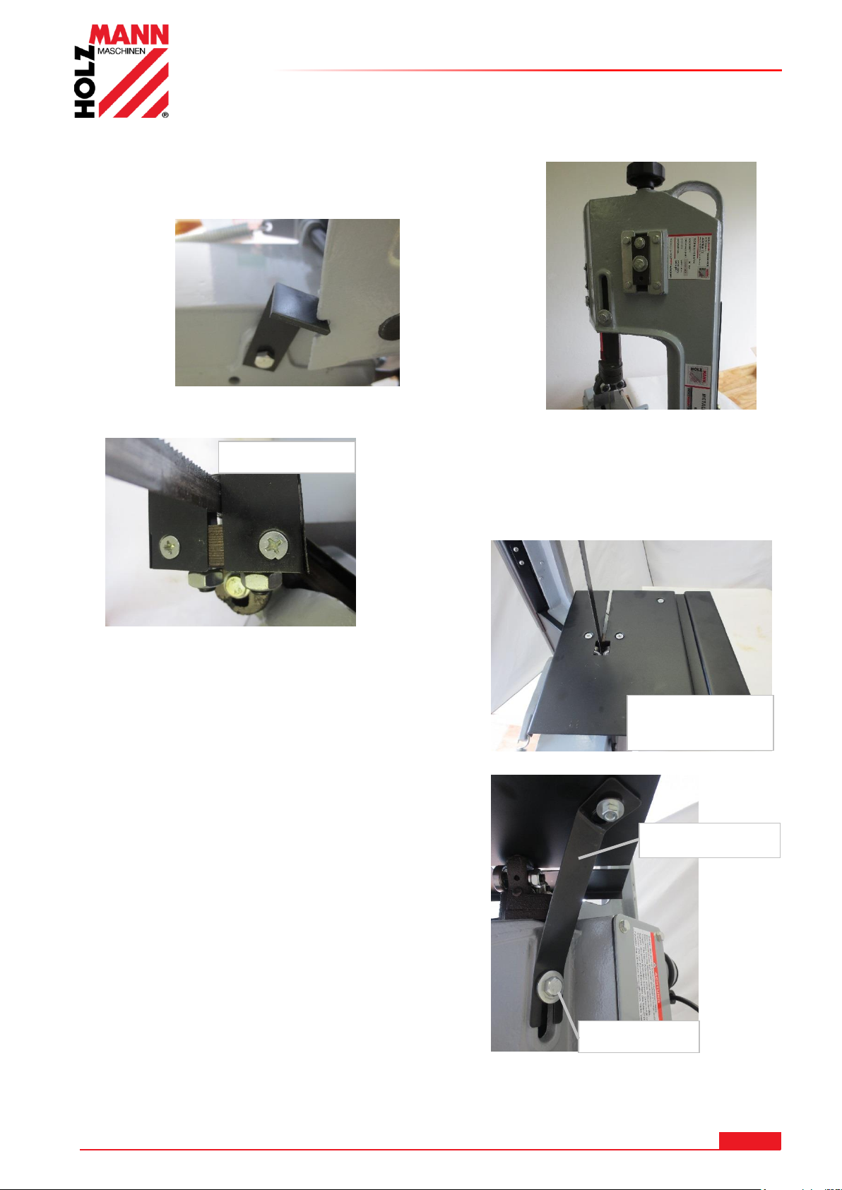
15.3.2 Vertical operation of the band saw
Raise the arm band saw in the 90 ° position and
clamp it on the base console with the fixing bracket.
Remove the protective cover.
The work talbe with the two screws attach on the
bandsaw blade guide.
Loosen the fixing screw at the bandsaw blade guide.
Insert the support bracket by the fixing screw
Screw on the table top with the countersunk screw
up and the washer and nut below.
The top bandsaw blade guide by unscrewing the
fixing nut (12) and screw into the threaded hole 2 be
pushed deeper.
As a result, the bandsaw blade is made even better.
Work table for
vertical sections
protective cover
fixing screw
support bracket
OPERATION
HOLZMANN MASCHINEN GmbH www.holzmann-maschinen.at 51
BS115 / BS128HDR
Page 52
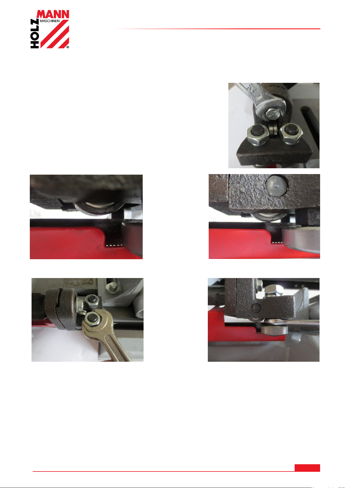
15.4 BS128HDR
Slightly loosen the left bandsaw blade
guide with the screw for fixation.
The tolerance by lowering the bandsaw blade guide leveling on bearing roll on the bandsaw blade
to zero.
Slightly loosen the nuts on either side
guide rollers with a wrench SW17.
With a wrench SW 12 is with the help of the
eccentric bearing roller according to externally or
internally displaced.
Repeat on both sides of the process until no play
between the bearing rollers.
The bandsaw blade should be centered on the upper
bearing role.
CAUTION: The two lower side rollers do not clamp!
After both bearing rollers are adjusted free of play, the two nuts tighten up the leadership roles.
15.4.1 Adjusting the vertical bandsaw blade guide for clippings
OPERATION
HOLZMANN MASCHINEN GmbH www.holzmann-maschinen.at 52
BS115 / BS128HDR
Page 53
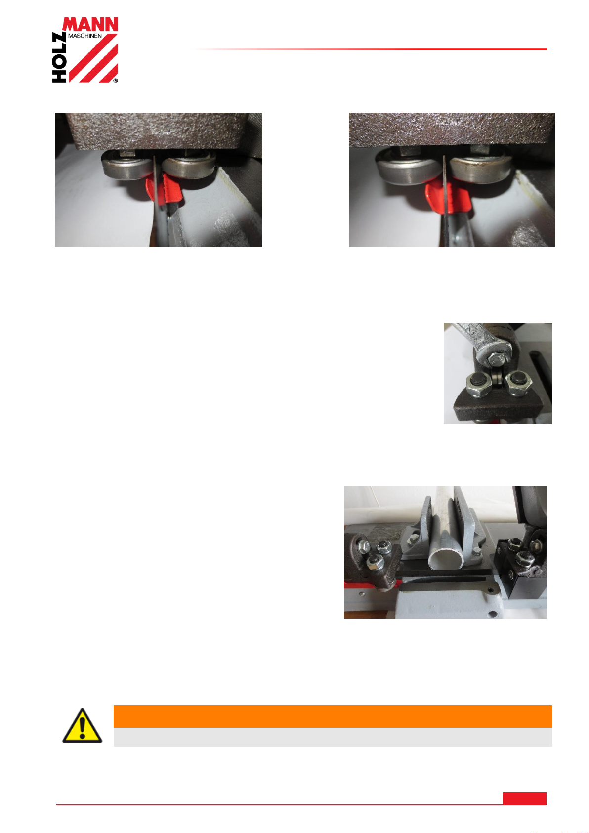
OPERATION
Example of a perfect adjustment of the bandsaw blade guide:
The bandsaw blade has too much play and is
therefore still cannot between the lateral
bearing rollers.
The saw blade is completely vertically without any
play between the lateral bearing rollers.
WA RN ING
Perform all the conversion work in isolation from the mains!
CAUTION:
Before tightening the bandsaw blade guide examine whether the saw band
is below set perfectly vertical and readjust the bandsaw blade guide
according vertically.
The bandsaw blade guide with the screw for fixing tighten.
NOTE: Check the 90 ° bandsaw blade guide with an angle gauge or with a rectangular
workpiece.
Repeat this process on the right if the saw band saw
blade guiding is not performed exactly vertical.
NOTE: The bandsaw blade guide slide (left / right) as
close as possible to the workpiece.
By loosening the fixing nuts (12), the blade guides
can be moved.
CAUTION: Bevel cuts are resulting from not exactly vertical set saw blade guides and too much
play between the lateral bearing rollers!
HOLZMANN MASCHINEN GmbH www.holzmann-maschinen.at 53
BS115 / BS128HDR
Page 54
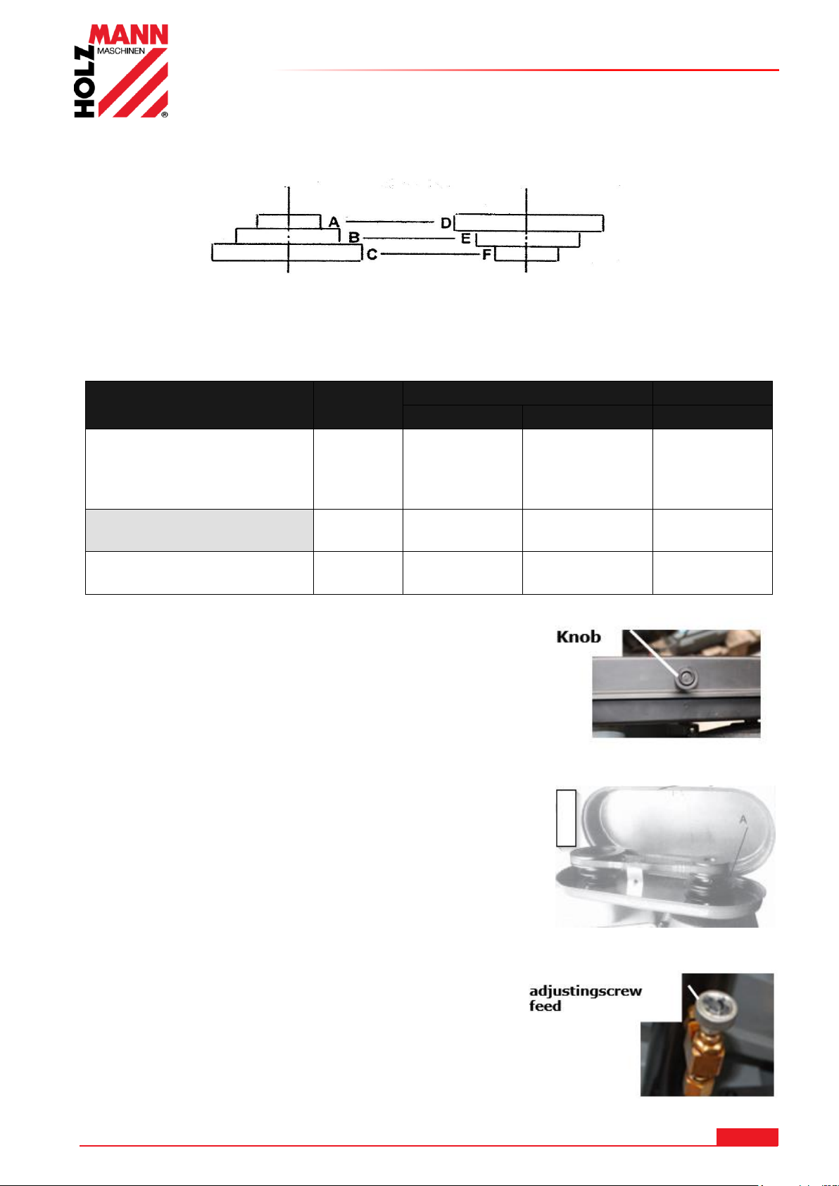
OPERATION
Material
speed
(m/min)
Belt position
Motor pulley
Drive pulley
Saw band
Stainless Steel
Stainless Steel ®
Tool steel - Alloy steel
Bearing bronze
23 A D
Bi-Metal
Structural steel - iron
mild steel - Thomas steel
34 B E
Bi-Metal
Brass - Aluminium
Similar materials
54 C F
HSS
Motor pilley Driven pulley
15.4.2 Select the saw blade speed
The saw blade is driven via a belt drive. Adjust the saw blade speed at the material to be cut.
Select the feed according to the following table.
15.4.3 Setting the blading speed
Open the lid by tightening the knob and the lid lift.
Now you can use the speed table in the lid to change the
cutting speed.
Turn the pulley easily and the V-belt in the provided disk groove screw.
CAUTION:
The V-belts must be connected to the opposite wheels
always in the same plane.
15.4.4 Setting the feed
The feed can be on the set screw on the Set hydraulic
lowering cylinder (4).
Select the feed according to the following table.
HOLZMANN MASCHINEN GmbH www.holzmann-maschinen.at 54
BS115 / BS128HDR
Page 55
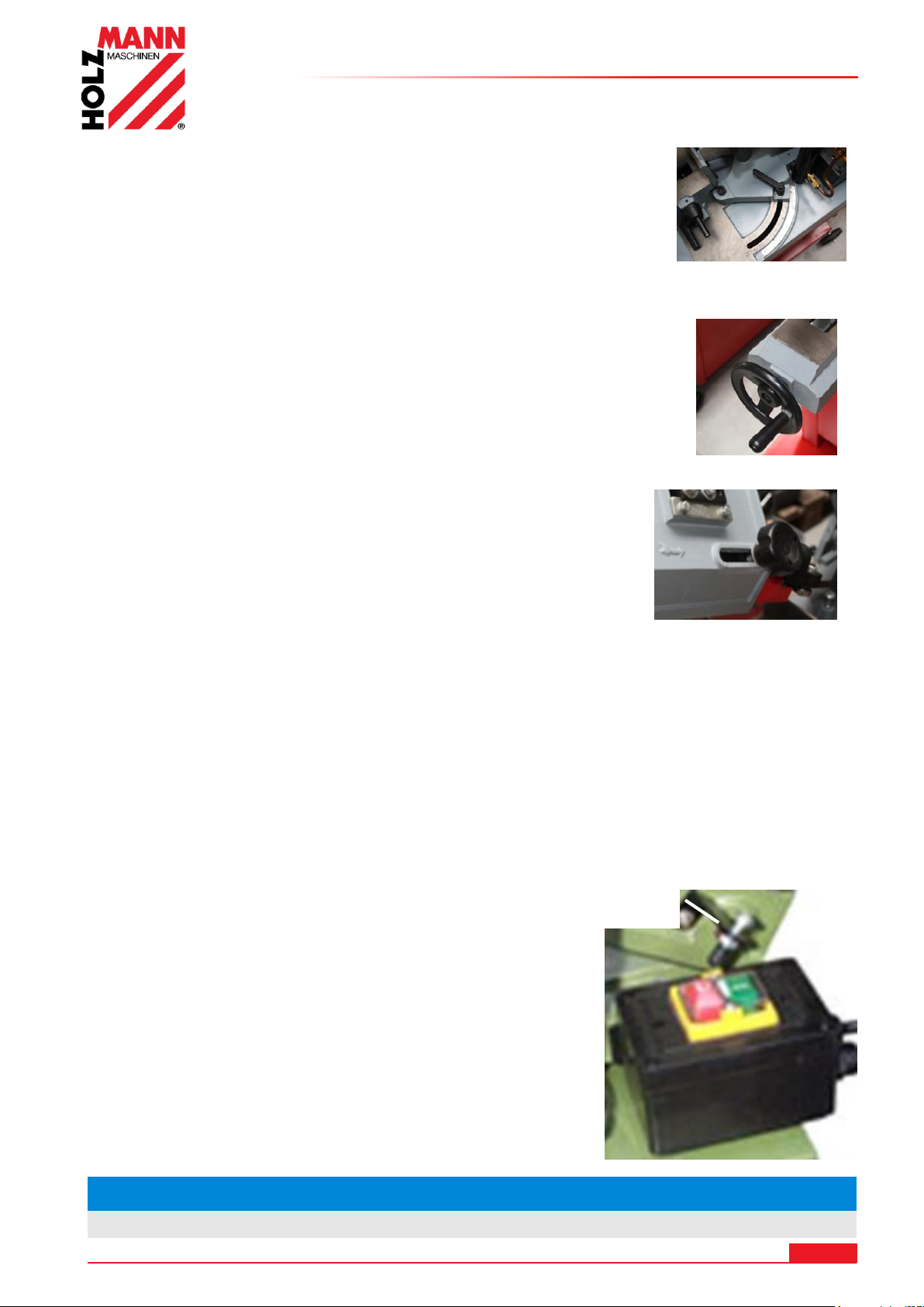
15.4.5 Adjustment of the miter angle
NO TE
The motor must run to full speed before start cutting!
Adjusting limit screw
Loosen the clamping screw (5).
Now you can move the entire saw arm.
By tightening the clamping screw (5) that is fixed again.
15.4.6 Clamping the workpiece
Place the workpiece in a vice and tighten it with the hand wheel (7) to.
15.4.7 Setting the saw band guide
OPERATION
Adjust the guide so that it approximately 2 cm in front of the
workpiece.
Loosen the hand wheel (8) and slide the guide.
Pull the handwheel back up again
15.4.8 Setting the blade tension
The bandsaw blade with the control knob (10) to voltage (2 - 3mm Test) set.
Check after a short test run and retighten if necessary.
15.4.9 Start/ Stop
Switch ON / OFF:
The machine can be switched on via the green ON button switching on and off with the red OFF
switch button.
The automatic switch off can by readjusting the limit screw to
be adjusted.
- Allow the engine to start up fully so that the saw blade at full
running speed.
- Run the saw arm to the bracket (3) to the workpiece.
- Let the saw arm by its own weight work through the
material.
- Do not apply pressure. The saw automatically turns off after
cutting through the material by triggering the OFF switch
button.
HOLZMANN MASCHINEN GmbH www.holzmann-maschinen.at 55
BS115 / BS128HDR
Page 56
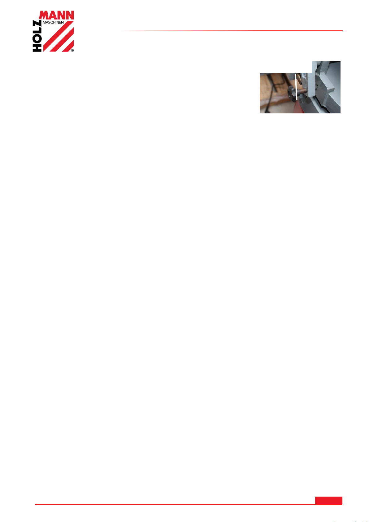
OPERATION
Positioning
knob
15.4.10 Sawing
Turn on the machine with the ON / OFF switch (9).
Remove the positioning knob.
The automatic feed to the saw arm moves automatically
downwards.
Do not apply pressure.
The saw automatically switches itself off after cutting the material
by triggering the off switch button.
Pull the saw arm into the air, and insert the positioning knob back in the hole.
THE TEETH OF THE SAW BLADE SHOULD GIVE THE MATERIAL TO BE CUT ALSO BE
ADJUSTED:
1. The thinner / narrower the workpiece, the higher teeth
2. Basic rule: it should be working at any given time at least 3 teeth in the material
NOTE: If the metal band saw a long time is not used, you can relax the saw band with the
adjustment of band tightening (10)
HOLZMANN MASCHINEN GmbH www.holzmann-maschinen.at 56
BS115 / BS128HDR
Page 57
MAINTENANCE
AT TE NT IO N
Perform all maintenance machine settings with the
machine being disconnected from the power supply!
Serious injury due to unintentional or automatic
activation of the machine!
NO TI CE
Clean your machine regularly after every usage – it prolongs the machines lifespan and is a
pre-requisite for a safe working environment.
Repair jobs shall be performed by respectively trained professionals only!
16 MAINTENANCE
The machine does not require extensive maintenance. If malfunctions and defects occur, let it be
serviced by trained persons only:
Check regularly the condition of the security stickers. Replace them if required.
Check regularly the condition of the machine!
Store the machine in a closed, dry location.
Before first operation you should lubricate all connecting parts.
16.1 Maintenance plan
After each workshift:
Raise the saw arm in the most upper position, secure it and close the hydraulic flow regulation
valve.
Detension the saw band.
Clean the machine entirely.
Lubricate the gliding surface of the vice and the blade slightly with some machinery oil.
After 50 hours of operation
Lubricate all connecting parts (if required, remove beforehand with a brush all swarfs and
dust)
HOLZMANN MASCHINEN GmbH www.holzmann-maschinen.at 57
BS115 / BS128HDR
Page 58
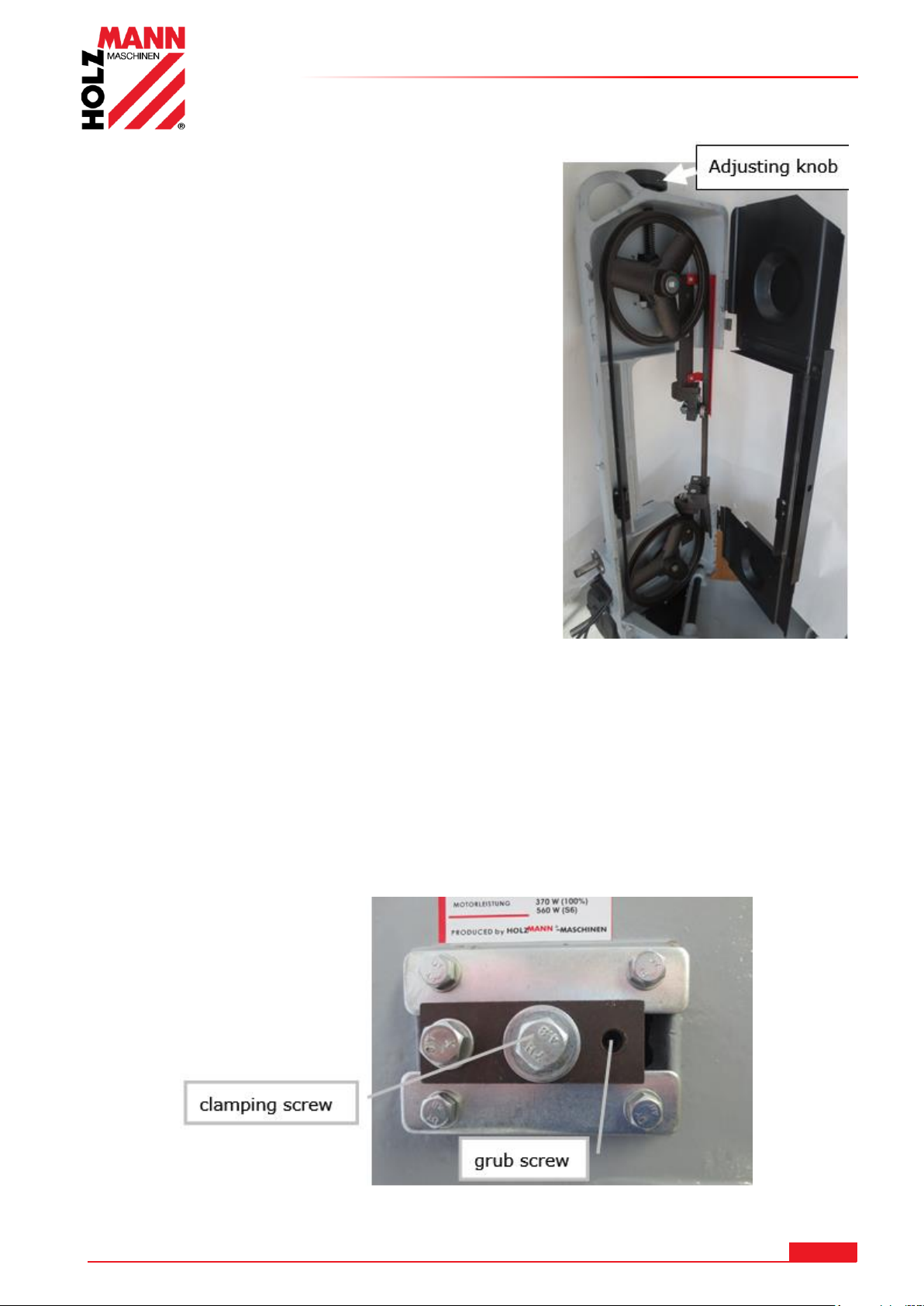
16.2 Changing saw blade
Move the metal belt in the vertical position and open
the saw band cover.
Loosen the saw band with the adjustment knob (10).
Saw band guard above remove.
Now pull off the old saw band of the impellers.
DANGER! Risk of injury! Wear work gloves.
The new bandsaw first insert in the blade guides and
then place it on the wheels.
WARNING: Respect the right direction of the teeth.
(see image left front of the saw arm)
Then put the saw band on the wheels.
The saw band with the control knob (2) tension (2 -
3mm test).
After a short test run check the tension and the tape /
chamber and tighten.
Saw blade guard screw on.
Close the saw band cover.
MAINTENANCE
16.3 Setting tape / camber
The impeller is factory aligned to the drive wheel. Should, however (especially after exchange) of
the saw blade is not straight or run from the impeller, an adjustment may be necessary.
The tape / camber can be adjusted.
The clamping screw slightly loose.
With the grub screw the tape can be adjusted.
Tighten the clamping screw.
HOLZMANN MASCHINEN GmbH www.holzmann-maschinen.at 58
BS115 / BS128HDR
Page 59
MAINTENANCE
NO TI CE
The usage of certain solutions containing ingredients damaging metal surfaces
as well as the use of scrubbing agents will damage the machine surface!
Clean the machine surface with a wet cloth soaked in a mild solution
16.4 Lubrication
Ball bearings do not require lubrication.
Lubricate the threaded rod of the jaw as needed
Cover all unpainted surfaces regularly with a thin layer of light-Maschi machine oil.
The transmission runs in an oil bath and requires about 1 time per year for an oil change:
Bring to the saw arm in horizontal position.
Remove the four screws of the gear cover and remove the cover.
Place a drain pan under the transmission housing.
Lift the saw arm out so that the oil flows.
Clean the gear case of coarser waste oil residues, fill a new TRANSMISSION OIL, and install the
cover properly.
Dispose of the used oil ecologically.
16.5 Cleaning
After each workshift the machine has to be cleaned. Remove chips etc. with a suitable tool. Do
not remove them by hand (cutting injury!). Remove dust as well.
16.6 Disposal
Do not dispose the machine in residual waste. Contact your local authorities for
information regarding the available disposal options. When you buy at your local
dealer for a replacement unit, the latter is obliged to exchange your old.
HOLZMANN MASCHINEN GmbH www.holzmann-maschinen.at 59
BS115 / BS128HDR
Page 60
TROUBLESHOOTING
Trouble
Possible cause
Solution
Machine does not start
Machine not connected to
power supply
Fuse of power circuit defect
or not suitable
Cable defect
Check all power connections
Change fuse
Change cable
Saw band does not come to full
speed, no power
To long extension cord
Power supply not matching
with motor requirements.
Weak, instable/volatile power
supply
change to suitable extension
cord with sufficient crosssection, insulation and length
Let check by electrician
Contact electric power
company
Motor gets hot very fast and
has weak performance
Motor does not receive power
on one or even 2 phases
Shut off machine
immediately. Let the
connection to supply circuit
be checked by an electrician!
Saw band runs in opposite
direction
2 of the 3 leading phases are
switched whether in Plug or
socket
Shut off machine
immediately. Let the
connection to supply circuit
be corrected by an
electrician!
Machine vibrates
Placed on uneven
underground
Motor or any other parts
loose
modify
check all screw joints if
tightened
Bad cuts
too high descent velocity
unsuitable saw band for
cutted material
worn saw band
saw band not tensioned
correctly
saw band guide outbalanced
Reduce the descent velocity
Use e.g. for stainless steel HQ
Bi-Metal bands only
replace
tension saw band correctly
readjust saw band guide
NO TI CE
Should you in necessary repairs not able to properly to perform or you
have not the prescribed training for it always attract a workshop to fix
the problem.
17 TROUBLESHOOTING
BEFORE YOU START WORKING FOR THE ELIMINATION OF DEFECTS, DISCONNECT THE
MACHINE FROM THE POWER SUPPLY.
MANY POTENTIAL SOURCES OF ERROR CAN BE CLEARED BY THE EXPERTLY CONNECTION
TO THE ELECTRICITY GRID.
HOLZMANN MASCHINEN GmbH www.holzmann-maschinen.at 60
BS115 / BS128HDR
Page 61
PREFAZIONE (IT)
HOLZMANN MASCHINEN GmbH
AT-4170 Haslach, Marktplatz 4
AUSTRIA
Tel +43 7289 71562 - 0
Fax +43 7289 71562 – 4
18 PREFAZIONE (IT)
Gentile Cliente,
Questo manuale d’uso contiene importanti informazioni e note riguardanti la messa in funzione e
l’utilizzo della sega a nastro per metalli BS 115 / BS128HDR
Di seguito il nome commerciale dell'apparecchio (vedi copertina) viene sostituito nelle presenti
istruzioni per l'uso con la definizione "macchina".
Le istruzioni per l'uso sono una componente della macchina e non devono essere
rimosse. Conservarle per consultazione futura e accluderle alla macchina in caso di
cessione della stessa a terzi!
Osservare le istruzioni per la sicurezza!
Prima della messa in servizio, leggere attentamente queste istruzioni. In questo modo si facilita
l'uso corretto, e si prevengono incomprensioni e danni eventuali.
Attenersi alle avvertenze e alle istruzioni per la sicurezza. La violazione può causare gravi lesioni.
A causa del costante sviluppo dei nostri prodotti è possibile che le immagini e i contenuti siano
leggermente differenti. Se doveste riscontrare errori, siete pregati di informarci.
Con riserva di modifiche tecniche!
Al ricevimento della merce controllatela immediatamente e fate annotare eventuali
contestazioni al momento della consegna, all'addetto al recapito, sulla lettera di
vettura!
I danni di trasporto devono essere segnalati a noi entro 24 ore.
Holzmann non può assumere alcuna garanzia per danni da trasporto non annotati.
Copyright
© 2017
Questa documentazione è protetta da copyright. Con riserva dei diritti costituzionali risultanti! In
particolare saranno perseguite legalmente la riproduzione, traduzione e il prelievo di foto e
immagini.
Foro competente è il Tribunale di Linz o il Tribunale di competenza di 4170 Haslach.
Indirizzo dei centri di assistenza clienti
HOLZMANN MASCHINEN GmbH www.holzmann-maschinen.at 61
BS115 / BS128HDR
Page 62
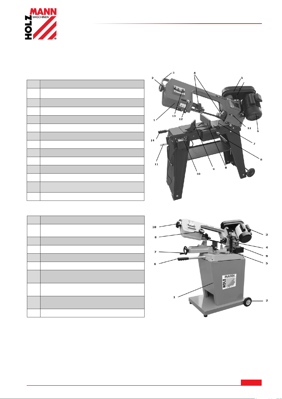
19 COMPONENTI
1
Braccio di taglio
2
Manopola di regolazione della tensione della lama a
nastro
3
Staffa del braccio di taglio
4
Guida della lama a nastro regolabile
5
Copri-cinghia
6
Motore
7
Vite di limitazione per la profondità di taglio
8
Ganascia di bloccaggio con angolazione regolabile
9
Ganascia di serraggio con angolazione regolabile
10
Interruttore ON - OFF
11
Manovella di tesatura per ganascia di serraggio
12
Vite di serraggio per guida della lama a nastro
13
Regolazione rotella di scorrimento e inclinazione del
nastro
14
Regolazione molla di avanzamento
1
Braccio di taglio
2
Manopola di regolazione della tensione
della lama a nastro
3
Staffa del braccio di taglio
4
Guida della lama a nastro regolabile
5
Copri-cinghia
6
Motore
7
Vite di limitazione per la profondità di
taglio
8
Ganascia di bloccaggio con angolazione
regolabile
9
Ganascia di serraggio con angolazione
regolabile
10
Interruttore ON - OFF
19.1 Tecniche
19.1.1 BS115
COMPONENTI
19.1.2 BS128HDR
HOLZMANN MASCHINEN GmbH www.holzmann-maschinen.at 62
BS115 / BS128HDR
Page 63
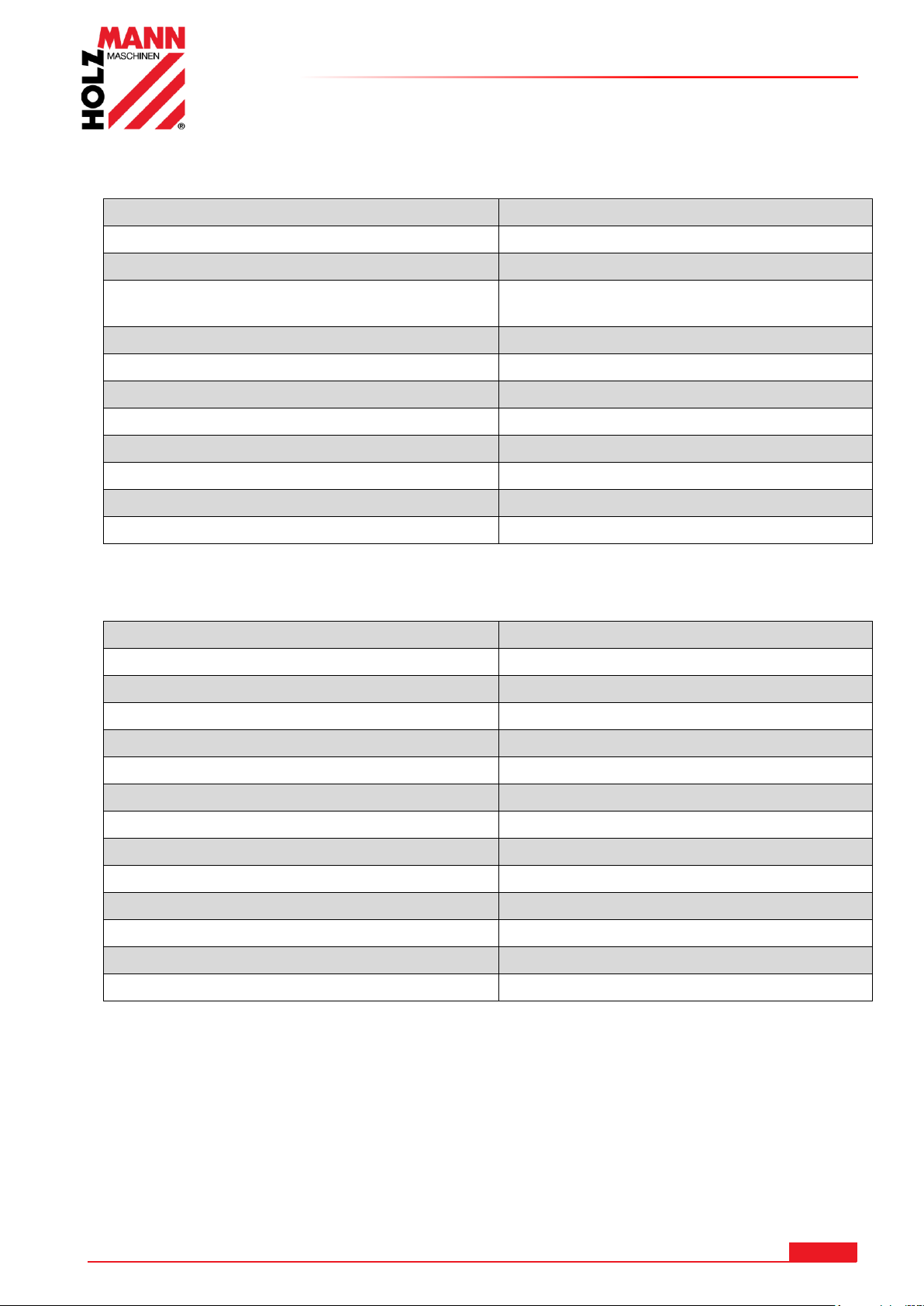
19.2 Dati tecnici BS115
Collegamento alla rete
230 / 400 V
Potenza motore
550 W
Avanzamento
20-29-50 m/min
Valori della lama a nastro
1638x0,6x12,5
mm
Ø max di un profilo tondo a 90°
110 mm
Ø max di un profilo tondo a 45°
75 mm
Max Hxl tubo quadro a 90°
110x140 mm
Max Hxl tubo quadro a 45°
110x75 mm
Dimensioni l x p x a
970x395x945 mm
Peso
56 kg
Livello di potenza sonora LWA
76 dB(A)
Tipo di protezione
IP 20
Collegamento alla rete
230 / 400 V
Potenza motore
550 W
Velocità di taglio
23 – 34 – 54 m/min
Valori della lama a nastro
1640 x 13 x 0,6 mm
Ø max di un profilo tondo a 90°
125 mm
Ø max di un profilo tondo a 45°
95 mm
Max Ø profilo tondo a 60°
50 mm
Max Hxl tubo quadro a 90°
100 x 150 mm
Max Hxl tubo quadro a 45°
95 x 76 mm
Max Hxl tubo quadro a 60°
50 x 56 mm
Dimensioni l x p x a
1000 x 550 x1100 mm
Peso
76 kg
Livello di potenza sonora LWA
76 dB(A)
Tipo di protezione
IP20
COMPONENTI
19.3 Dati tecnici BS128HDR
HOLZMANN MASCHINEN GmbH www.holzmann-maschinen.at 63
BS115 / BS128HDR
Page 64
SICUREZZA
AVVERTENZA
Utilizzare esclusivamente lame a nastro autorizzate per questa macchina!
Non utilizzare mai lame difettose!
Non utilizzare mai la macchina con dispositivi di protezione difettosi
divisori non installati
Rimuovere o modificare le componenti di sicurezza può causare danni
all’apparecchio e gravi lesioni!
Bloccare sempre il pezzo in lavorazione nella morsa durante la procedura di
taglio!
Non rimuovere mai trucioli e schegge quando la macchina è in funzione!
ALTISSIMO RISCHIO DI LESIONI!
20 SICUREZZA
20.1 Uso conforme previsto
Usare la macchina solo in condizioni tecniche perfette e conformemente alla destinazione d'uso,
nel rispetto delle norme di sicurezza e consapevoli dei pericoli! Far rimuovere immediatamente le
anomalie che possono pregiudicare la sicurezza! Si devono osservare le condizioni d’uso,
manutenzione e riparazione indicate dal produttore e attenersi alle avvertenze per la sicurezza
contenute nel manuale.
In generale è vietato modificare e rendere inefficaci i dispositivi tecnici di sicurezza della
macchina!
La macchina è progettata esclusivamente per le seguenti attività:
Per tagliare metalli, pezzi colati e materie plastiche
Per un uso diverso o che esula da questo e per danni materiali o lesioni da
questo derivanti HOLZMANN-MASCHINEN non si assume alcuna responsabilità o
non fornisce alcuna garanzia
20.2 Uso improprio non ammesso
Non è consentito l'uso della macchina in condizioni che esulano dai limiti indicati nel manuale
presente.
La macchina non è progettata per l'uso in condizioni a rischio di esplosione
Non è consentito il funzionamento della macchina con materiali che non sono espressamente
indicati in questo manuale.
Non è consentito l'utilizzo di utensili che non sono idonei all'uso con la macchina.
Sono vietate eventuali modifiche strutturali alla macchina.
E' vietato l'uso della macchina in un modo o per scopi che non corrispondano al 100% alle
istruzioni di questo manuale.
Non lasciare mai la macchina incustodita, soprattutto se ci sono bambini nelle vicinanze!
20.3 Avvertenze per la sicurezza
I segnali di avvertimento e/o le etichette applicate sulla macchina, che sono illeggibili
o sono stati rimossi, devono essere sostituiti immediatamente!
Le leggi e regolamenti locali possono prevedere un limite minimo di età dell'operatore
e limitare l'uso di questa macchina!
Per evitare malfunzionamenti, danni materiali o danni alla salute osservare
TASSATIVAMENTE le istruzioni seguenti:
HOLZMANN MASCHINEN GmbH www.holzmann-maschinen.at 64
BS115 / BS128HDR
Tenere l'area di lavoro e il pavimento attorno alla macchina puliti e privi di
olio, grasso e residui di materiale!
Fornire un'illuminazione sufficiente nell'area di lavoro della macchina!
Lavorare in ambienti ben aerati!
Non sovraccaricare la macchina!
Page 65
SICUREZZA
Fare attenzione ad assumere sempre una posizione sicura durante il lavoro.
Tenere le mani lontano dalla lama durante l'uso
In caso di stanchezza, mancanza di concentrazione o se si è sotto l'effetto di
farmaci, alcol o droga è vietato lavorare alla macchina!
La macchina deve essere azionata da una sola persona
La macchina deve essere utilizzata solo da persone addestrate (con
conoscenza e comprensione di questo manuale), che non hanno capacità
motorie limitate rispetto ai lavoratori convenzionali.
Le persone non autorizzate, soprattutto i bambini, e le persone non
istruite devono essere tenute lontano dalla macchina in funzione!
Fare attenzione che nessuno sosti nella zona di pericolo (distanza
minima: 2m)
Quando si lavora alla macchina, non indossare gioielli allentati, indumenti
ampi, cravatte o capelli lunghi e sciolti (usare una retina per capelli!).
Gli oggetti liberi possono essere catturati causando lesioni gravissime!
Durante interventi con e sulla macchina, indossare sempre dispositivi di
sicurezza adeguati (abiti da lavoro attillati, guanti di sicurezza secondo EN
388, classe 3111, occhiali di protezione, paraorecchie e scarpe di sicurezza
S1)!
Non è mai consentito lasciare la macchina in funzione incustodita! Prima di
allontanarsi dall'area di lavoro, spegnere la macchina e attendere che si sia
completamente arrestata!
Prima di svolgere lavori di manutenzione o regolazione la macchina deve
essere scollegata dall'alimentazione di tensione!
Assicurarsi che la macchina sia spenta prima di collegarla
all'alimentazione elettrica
Non utilizzare mai la macchina con interruttore difettoso
Utilizzare solo connettori inalterati, adatti alla presa (nessun adattatore
con le macchine con collegamento a massa)
Ogni volta che si lavora con una macchina alimentata elettricamente, si deve
prestare la massima attenzione! Sussiste pericolo di scossa elettrica, incendio,
lesioni da taglio;
Proteggere la macchina dal bagnato (pericolo di cortocircuito!)
Utilizzare elettroutensili e macchine elettriche non in vicinanza di liquidi e gas
infiammabili (pericolo di esplosione!)
Controllare regolarmente eventuali danni del cavo di allacciamento
Non usare mai il cavo per trasportare la macchina o per fissare in utensile
Proteggere il cavo dal calore, olio e spigoli taglienti
Evitare il contatto del corpo con parti messe a terra
Sono possibili gravi lesioni alle mani dovute a spigoli vivi.
20.4 Rischi Residui
Anche rispettando tutte le norme di sicurezza e con un uso conforme previsto occorre fare
attenzione ai seguenti rischi residui:
• Pericolo di lesioni per mani/dita durante l'uso dovute alla lama della sega.
• Pericolo di lesioni/di taglio per sbordi di taglio non sbavati.
• Pericolo di lesioni da contatto con componenti sotto tensione.
• Pericolo di lesioni per rottura o proiezione dalla lama e parti di essa, soprattutto in caso di
sovraccarico e anche con senso di rotazione errato.
• La perdita dell'udito, a meno che non sono stati presi provvedimenti da parte dell'utente per la
protezione dell'udito.
• Pericolo di lesioni per gli occhi dovuto a parti proiettate, anche se si indossano gli occhialini
protettivi.
HOLZMANN MASCHINEN GmbH www.holzmann-maschinen.at 65
BS115 / BS128HDR
Page 66
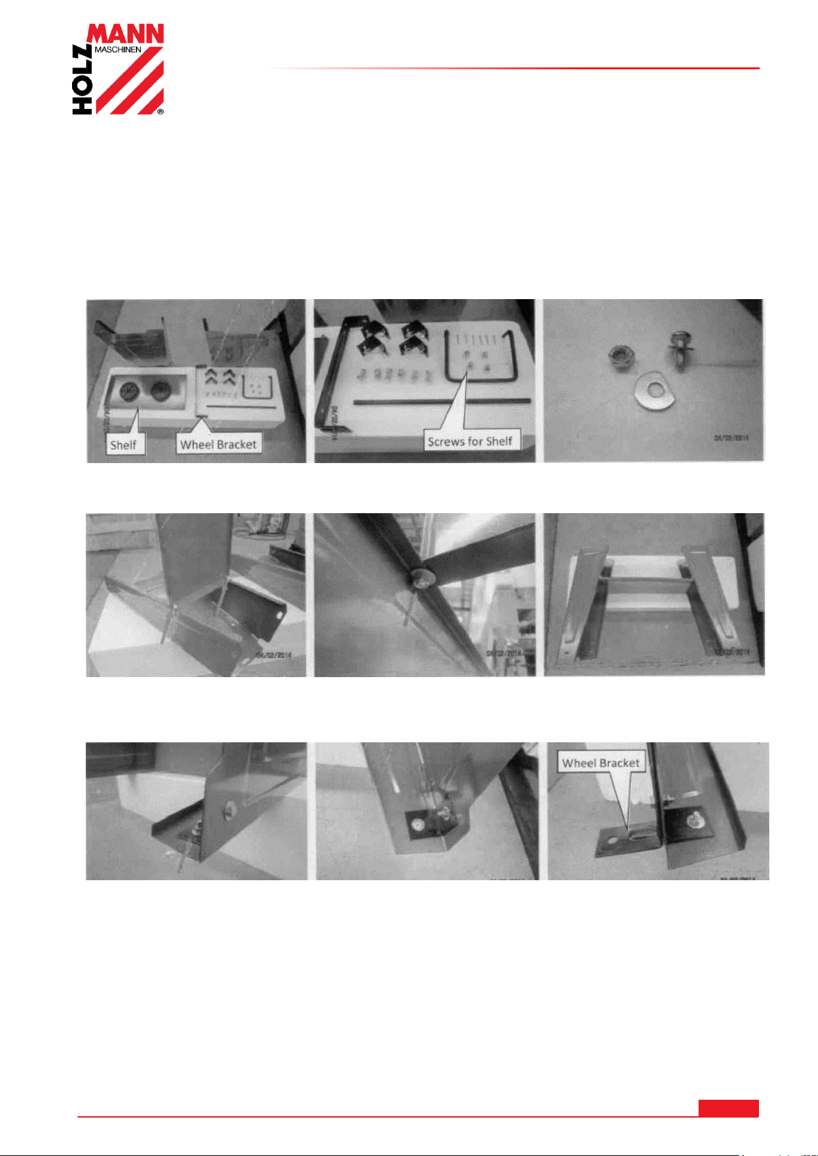
MONTAGGIO
1. Contenuto della fornitura -pezzi di montaggio- Viti, rondelle, dadi
3. Ribaltare il pezzo laterale e avvitare il supporto centrale
come illustrato nella figura
4. Avvitare entrambi i
pezzi montati.
5. Posizionare le 2 staffe angolari sui fori corrispondenti e avvitarle 6. Avvitare l’assale in
posizione contrapposta alle 2
staffe angolari
21 MONTAGGIO
Dopo aver ricevuto la fornitura, verificare che tutti i pezzi siano a posto. Segnalare danni o parti
mancanti immediatamente al vostro rivenditore o allo spedizioniere. I danni visibili dovuti al
trasporto devono essere inoltre annotati immediatamente sulla bolla di consegna in conformità
con le disposizioni della garanzia, altrimenti la merce si considera come correttamente ricevuta.
21.1 7.1 BS115
HOLZMANN MASCHINEN GmbH www.holzmann-maschinen.at 66
BS115 / BS128HDR
Page 67
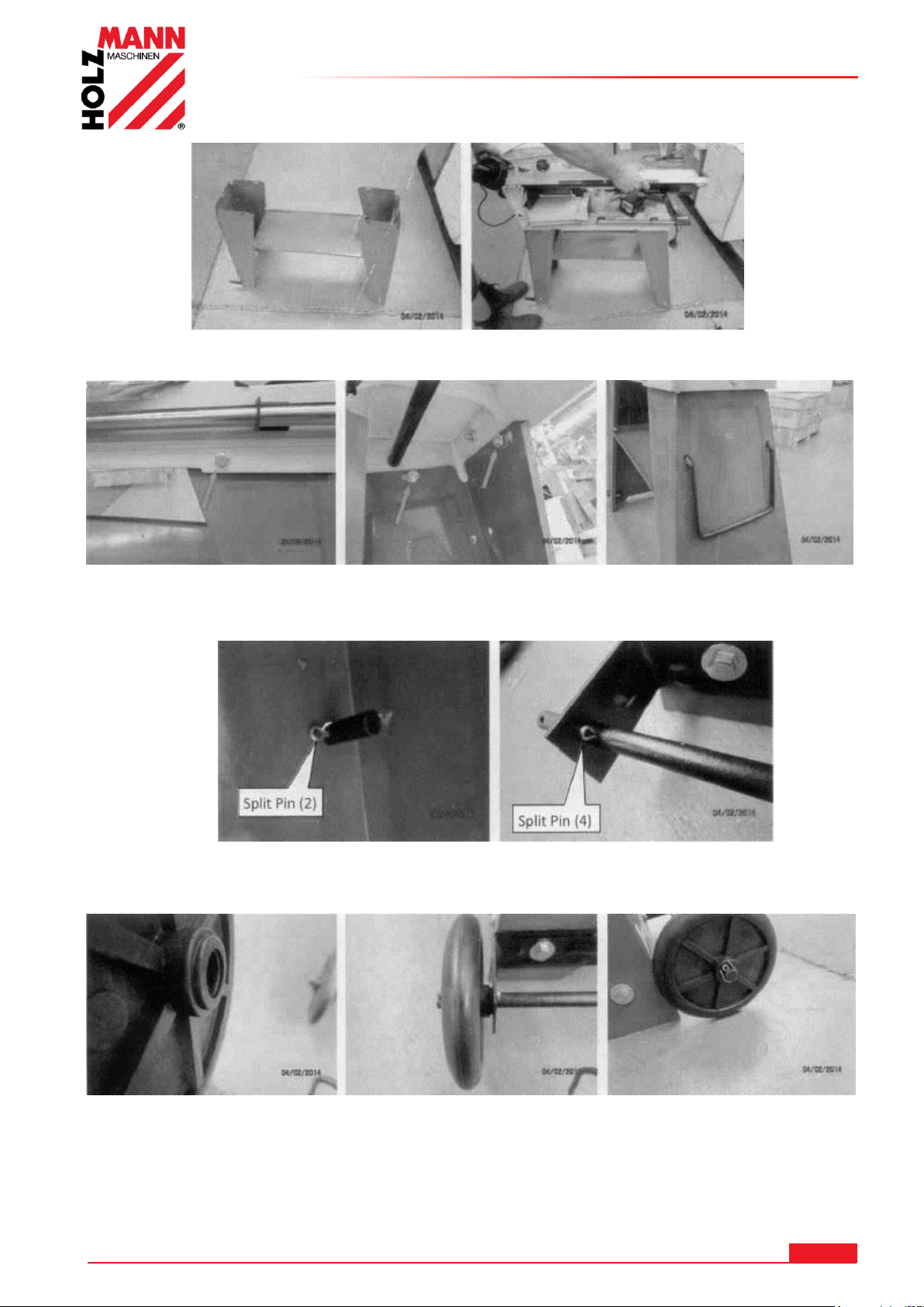
MONTAGGIO
Con l’aiuto di una seconda persona, sistemare delicatamente la sega a nastro per
metalli sulla struttura di supporto stando attenti che la macchina non scivoli.
8. Avvitare la base sulla struttura di supporto. 9. Installare la maniglia
10. Bloccare la maniglia dall’interno con una copiglia. 11. Inserire l’assale e bloccarlo su
entrambi i lati con delle copiglie.
12. Mettere in posizione la ruota e bloccarla con una copiglia. 13. Avvitare anche la
seconda ruota
HOLZMANN MASCHINEN GmbH www.holzmann-maschinen.at 67
BS115 / BS128HDR
Page 68
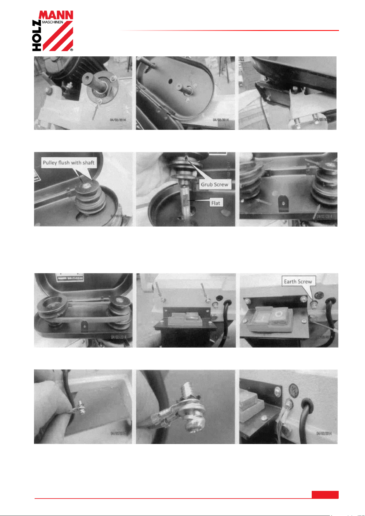
MONTAGGIO
14. Svitare le 2 viti sulla destra e la vite di fissaggio del motore. Avvitare la copertura
della cinghia come illustrato nell’immagine.
15. Inserire la puleggia del motore -fig. a sinistra- con la scanalatura della linguetta di
aggiustamento sull’albero motore. Inserire accuratamente la puleggia di azionamento con la
vite senza testa -fig. centrale- sulla superficie ribassata come illustrato nell’immagine.
Serrare entrambe le pulegge con le viti senza testa.
17. Mettere in posizione la cinghia trapezoidale. 18. Avvitare l’elemento di commutazione.
Far eseguire i lavori elettrici esclusivamente a persone qualificate.
19. Avvitare i 2 cavi di terra come illustrato nell’immagine.
HOLZMANN MASCHINEN GmbH www.holzmann-maschinen.at 68
BS115 / BS128HDR
Page 69
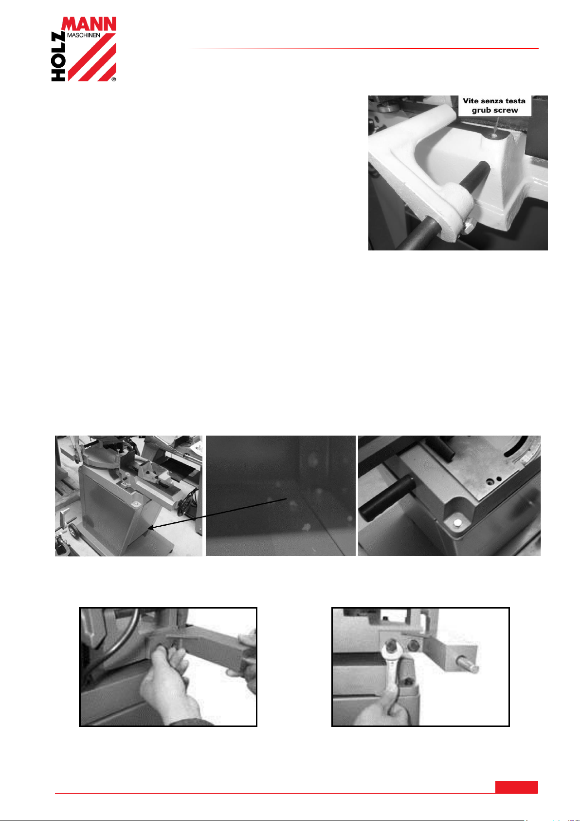
20. Montare l’arresto di finecorsa.
Inserire il tondino di guida in acciaio nella base e
serrarlo con l’apposita vite senza testa.
Montare l’arresto di finecorsa sul tondino di guida in acciaio
21.2 BS128HDR
MONTAGGIO
La BS 128HDR è praticamente montata. Adesso dovrete solamente procedere ad assemblare la
base di supporto.
Come prima cosa, montate le ruote.
A questo punto è necessario assemblare il supporto di base (avvitamento interno con il carrello).
Posizionare infine la sega a nastro sul supporto di base e avvitarla saldamente.
Avvitare l’ammortizzatore a molla
Fissare il supporto della molla alla console come illustrato nell’immagine
HOLZMANN MASCHINEN GmbH www.holzmann-maschinen.at 69
BS115 / BS128HDR
Page 70
MONTAGGIO
ATTENZIONE
Per lavori su una macchina non collegata a massa: Sono possibili
gravi lesioni dovute a scossa elettrica in caso di malfunzionamento!
Pertanto vale la regola: La macchina deve essere usata su una presa con
messa a terra.
AVVERTENZA
Il sollevamento e il trasporto della macchina devono essere svolti solo da
personale qualificato e devono essere eseguiti con le attrezzature
adeguate.
21.3 Postazione di lavoro
Scegliere un posto adeguato alla macchina. Prendere sempre in considerazione tutti i requisiti di
sicurezza della macchina. Il pavimento/base deve essere solido, piano e resistente alle vibrazioni
e deve poter sopportare almeno 2 volte il peso netto della macchina.
Il posto scelto deve garantire un allacciamento adatto alla rete elettrica.
È necessario mantenere una distanza di almeno 0.8 m per mettere al sicuro tutt'attorno la
macchina. Davanti e dietro la macchina deve essere prevista la distanza necessaria per
alimentare i pezzi da lavorare lunghi.
21.4 Trasporto/scarico della macchina
Sollevarla dall'imballo per montarla e posizionarla sulla postazione di lavoro: Solo con dispositivi
di sollevamento idonei!
Tenere presente che qualsiasi attrezzatura di sollevamento (gru, carrelli elevatori, cintura di
sollevamento, ecc.) deve essere in buone condizioni.
Per manovrare la macchina nell'imballo è possibile usare anche un carrello elevatore per bancali o
un carrello elevatore a forche frontali.
Eliminare il conservante che viene applicato come protezione anti-corrosiva alle parti non
verniciate. Questa operazione può essere fatta con i comuni solventi. Non utilizzare solventi nitro
o sostanze simili e non usare in nessun caso l'acqua.
21.5 Allacciamento elettrico
Le seguenti istruzioni sono rivolte ad un elettricista specializzato. L'allacciamento della macchina
deve essere eseguito esclusivamente da un elettricista specializzato!
1. L'allacciamento elettrico della macchina è predisposto per il funzionamento con una
presa con messa a terra!
2. Non è consentito manipolare il connettore!
3. Il conduttore di terra è giallo-verde!
4. La rete di alimentazione deve essere protetta con fusibile 16A.
5. Controllare che la tensione di rete coincida con i requisiti della macchina.
6. Dopo l'allacciamento elettrico controllare che il senso di rotazione sia corretto.(400V)
7. Se la macchina scorre nella direzione sbagliata, si devono scambiare due fasi
conduttive.
8. In caso di riparazione o di sostituzione, il conduttore di terra non deve essere allacciato a
una presa sotto tensione!
9. Accertarsi che un eventuale cavo di prolunga sia in buono stato e sia idoneo per il
trasferimento di potenza. Un cavo sottodimensionato riduce il trasferimento di potenza e
si riscalda molto.
10.
Un cavo danneggiato deve essere sostituito immediatamente!
HOLZMANN MASCHINEN GmbH www.holzmann-maschinen.at 70
BS115 / BS128HDR
Page 71
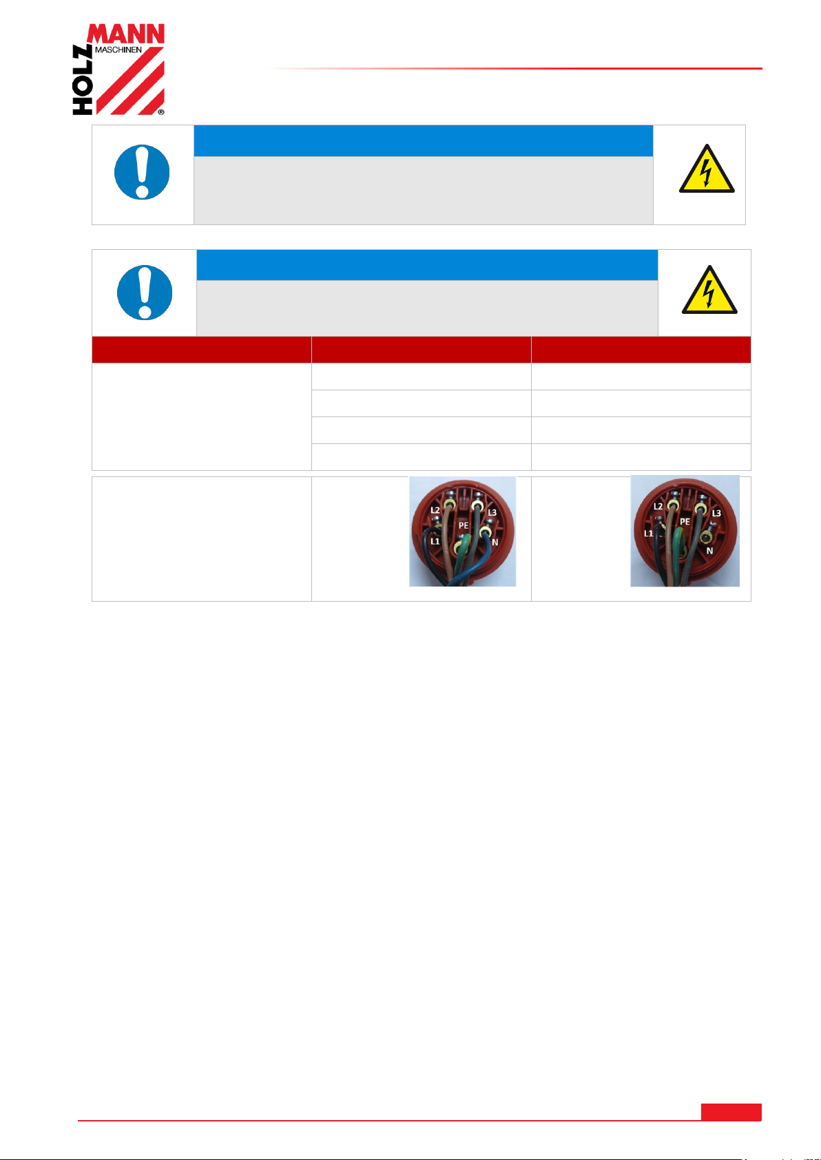
MONTAGGIO
NOTA
L'uso è ammesso solo con dispositivo di sicurezza per
correnti di guasto (RCD con corrente di guasto massima
di 30mA).
NOTA
Utilizzare esclusivamente cavi di prolunga omologati
con sezione del cavo indicata nella seguente tabella.
Tensione
Prolunga
Sezione del cavo
220 V-240 V
50 Hz
<27 m
1,5 mm2
<44 m
2,5 mm2
<70 m
4,0 mm2
<105 m
6,0 mm2
Collegamento a spina
400V:
5-adrig:
con
conduttore N
4-adrig:
senza
conduttore N
HOLZMANN MASCHINEN GmbH www.holzmann-maschinen.at 71
BS115 / BS128HDR
Page 72
22 USO
AVVERTENZA
Eseguire qualsiasi intervento di adattamento o di
regolazione solo una volta staccata la corrente
elettrica!
NOTA
Prima di iniziare a lavorare con la sega a nastro, controllare:
Le condizioni tecniche generali della macchina
Che i dispositivi di sicurezza sono integri e funzionanti
Se la lama a nastro presenta segni di usura e sostituirla
all’occorrenza
Che i componenti mobili non sono bloccati
Che tutti i componenti sono ben fissati e funzionano
correttamente, in particolare le viti della protezione della lama a
nastro e della leva!
Che tutti gli strumenti utilizzati durante gli interventi di
manutenzione e di riparazioni sulla macchina sono stati
rimossi.
Che la protezione della lama a nastro sia posizionata il più vicino
possibile al pezzo in lavorazione.
Prima di ogni taglio, controllare quanto segue:
L’angolazione è stata correttamente impostata?
La morsa è stata adeguatamente fissata?
Assicurarsi che il materiale in lavorazione sia
correttamente bloccato nella morsa.
Assicurarsi che il liquido di raffreddamento circoli correttamente
Direzione di marcia della lama a nastro
Pezzi in lavorazione molto lunghi e sporgenti devono essere sorretti da
un cavalletto
Far raggiungere sempre il massimo dei giri al motore prima di
iniziare a tagliare
Non avviare mai la macchina con la lama a nastro compressa!
Utilizzare la macchina solo in perfette condizioni. Prima di ogni utilizzo eseguire un controllo
visivo della macchina. I dispositivi di sicurezza, i cavi elettrici e gli elementi di comando
devono essere controllati con la massima precisione. Controllare che i collegamenti a vite
non siano danneggiati e siano bene in sede.
22.1 8.1 Istruzioni per l'uso
USO
HOLZMANN MASCHINEN GmbH www.holzmann-maschinen.at 72
BS115 / BS128HDR
Page 73
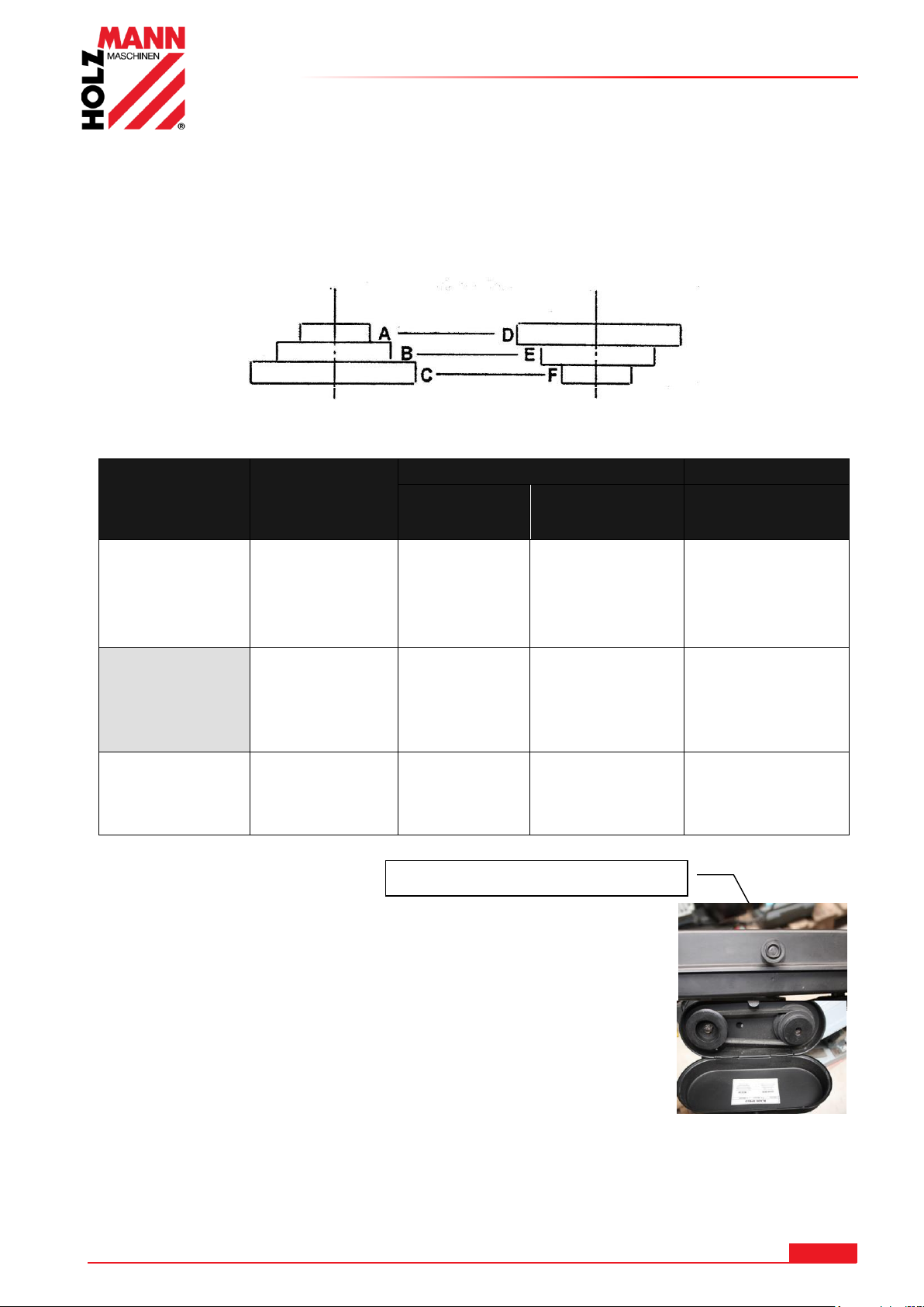
Viti a bottone o viti per lamiera
22.2 BS115
Materiale
Velocità
(m/min)
Regolazione cinghia
Puleggia del
motore
Puleggia di
trasmissione
Lama
sega a
nastro
Acciaio inox
Nirosta ® acciaio
per utensili in lega
Bronzina
20
A
D
Bimetallo
Acciaio da
costruzione
ferro acciaio
fuso
Acciaio Thomas
29
B E
Bimetallo
Ottone
alluminio
Materiali
simili
50
C F
HSS
Puleggia del motore
Puleggia motrice
22.2.1 Selezionare la velocità della lama a nastro della sega
La lama a nastro viene azionata tramite una trasmissione a cinghia. Adeguare la velocità della
lama a nastro al materiale da tagliare.
Regolare l’avanzamento in base alla seguente tabella.
USO
Svitare la vite sul coperchio e ribaltare il coperchio.
Allentare le due viti sul supporto del motore.
Sistemare dunque la cinghia nella giusta posizione indicata nella
tabella - Tabella visibile anche sul coperchio.
Ristringere le due viti sul supporto del motore, richiudere il coperchio
e riavvitare le viti.
HOLZMANN MASCHINEN GmbH www.holzmann-maschinen.at 73
BS115 / BS128HDR
Page 74
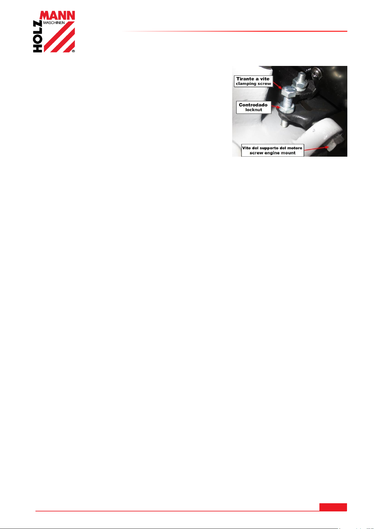
22.2.2 Regolazione tensione della cinghia trapezoidale
Le due viti del supporto del motore sono leggermente
allentate.
Allentare il controdado e regolare la tensione della cinghia
trapezoidale fino a raggiungere 2-5 mm di gioco con il
tirante a vite.
Serrare il controdado.
Avvitare le viti su entrambi i lati del supporto del motore.
LA DENTELLATURA DELLA LAMA A NASTRO DOVREBBE
ESSERE ADEGUATA AL MATERIALE DA TAGLIARE:
1. Più fine / stretto è il pezzo in lavorazione, più alta dovrà essere la dentellatura
2. Regola di base: in ogni momento dovrebbero lavorare almeno 3 denti nel materiale
22.2.3 Impostare l’angolo per tagli obliqui
USO
Allentare il fissaggio della ganascia di bloccaggio (8)
Regolare la ganascia di bloccaggio fino a raggiungere l’angolazione desiderata.
22.2.4 Bloccaggio del pezzo in lavorazione
Sistemare il pezzo in lavorazione sulla ganascia di bloccaggio e fissarlo con la ganascia di
serraggio (9). La ganascia di serraggio può essere regolata con una manovella (11).
22.2.5 Regolazione tensione della lama a nastro
Controllare la tensione della lama a nastro: Premete leggermente con il pollice contro la lama a
nastro: dovrebbe cedere di ca. 1 mm.
Nel caso la lama a nastro non fosse correttamente tesa, sarà necessario aggiustare la tensione
con il pomello di regolazione (2).
22.2.6 Regolazione dell’avanzamento
Girando la maniglia della molla di avanzamento (14) verso destra, la molla viene tesa e
l’avanzamento ridotto. Girandola a sinistra, l’avanzamento viene alzato.
HOLZMANN MASCHINEN GmbH www.holzmann-maschinen.at 74
BS115 / BS128HDR
Page 75
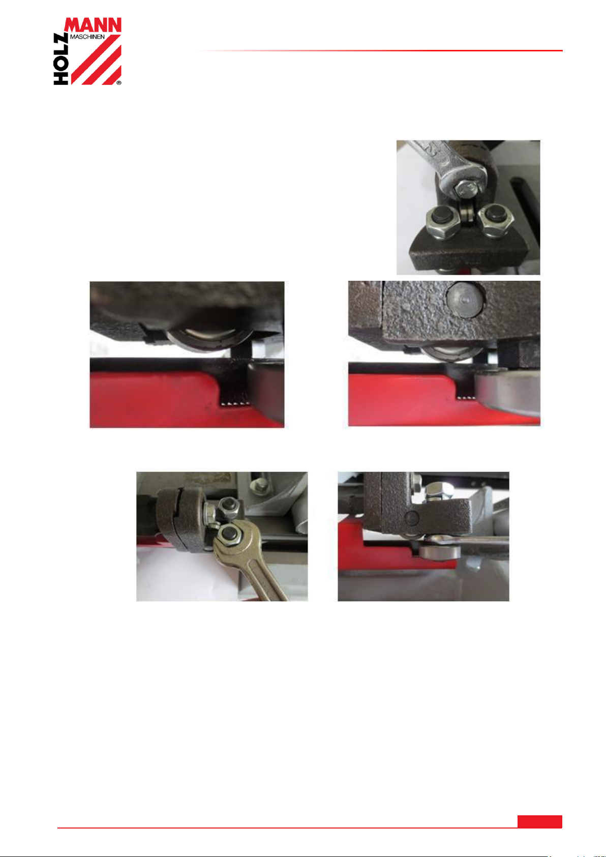
22.2.7 Regolazione guida della lama a nastro verticalmente rispetto al pezzo di taglio
Allentare leggermente la guida della
lama a nastro girando la vite di
fissaggio.
Abbassando la guida della lama a nastro con il cuscinetto a rullo sulla stessa si azzera il gioco.
Allentare leggermente i dadi su entrambi
di rulli laterali delle guide con una chiave a
bocca SW17.
Con una chiave a bocca SW 12 e l’aiuto di
una vite dell’eccentrico, il cuscinetto a rullo
viene spostato dall’esterno verso l’interno.
Ripetere la procedura su entrambi i lati finché
non vi è più gioco tra i cuscinetti a rullo.
La lama a nastro dovrebbe essere allineata
centralmente rispetto al cuscinetto a rullo
superiore.
ATTENZIONE: Non serrare troppo i
cuscinetti a rullo laterali!
USO
HOLZMANN MASCHINEN GmbH www.holzmann-maschinen.at 75
BS115 / BS128HDR
Page 76
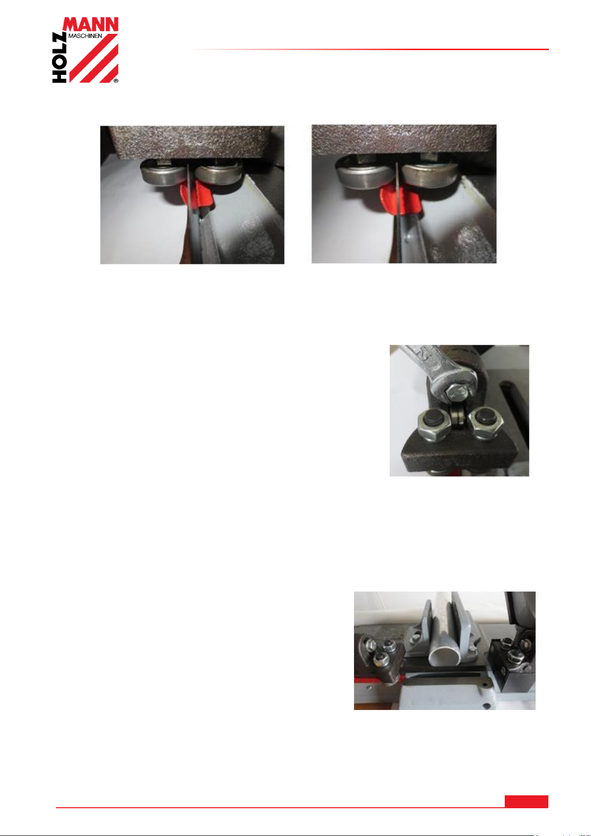
USO
Una volta regolati i due cuscinetti a rullo, sarà necessario serrare i due dadi sopra gli stessi.
Esempio di una regolazione perfetta della guida della lama a nastro:
La lama a nastro ha ancora troppo gioco e
dunque risulta inclinata tra i cuscinetti a rullo
laterali.
La lama a nastro senza gioco si trova in
posizione perfettamente verticale rispetto
ai cuscinetti a rullo laterali.
ATTENZIONE:
Prima di serrare la guida della lama a nastro, assicurarsi che la
lama a nastro al di sotto sia perfettamente verticale ed
eventualmente correggere la relativa guida della lama in senso
veritcale.
Serrare nuovamente la guida della lama a nastro
tramite la vite di fissaggio.
NOTA: Con un calibro angolare da 90° oppure in corrispondenza di un pezzo in
lavorazione rettangolare, verificare l’impostazione a 90° della guida della lama a
nastro.
Ripetere questa procedura sulla guida della lama a nastro di destra nel caso che la lama a
nastro non dovesse scorrere perfettamente in senso verticale.
NOTA: Avvicinare il più possibile la guida della lama
a nastro di destra e di sinistra al pezzo in lavorazione.
Allentando i dadi di serraggio (12) è possibile
spostare le guide della lama a nastro su entrambi i
lati.
ATTENZIONE: Tagli inclinati si verificano quando le guide della lama a nastro non sono
esattamente verticali e vi è troppo gioco tra i cuscinetti a rullo laterali!
HOLZMANN MASCHINEN GmbH www.holzmann-maschinen.at 76
BS115 / BS128HDR
Page 77
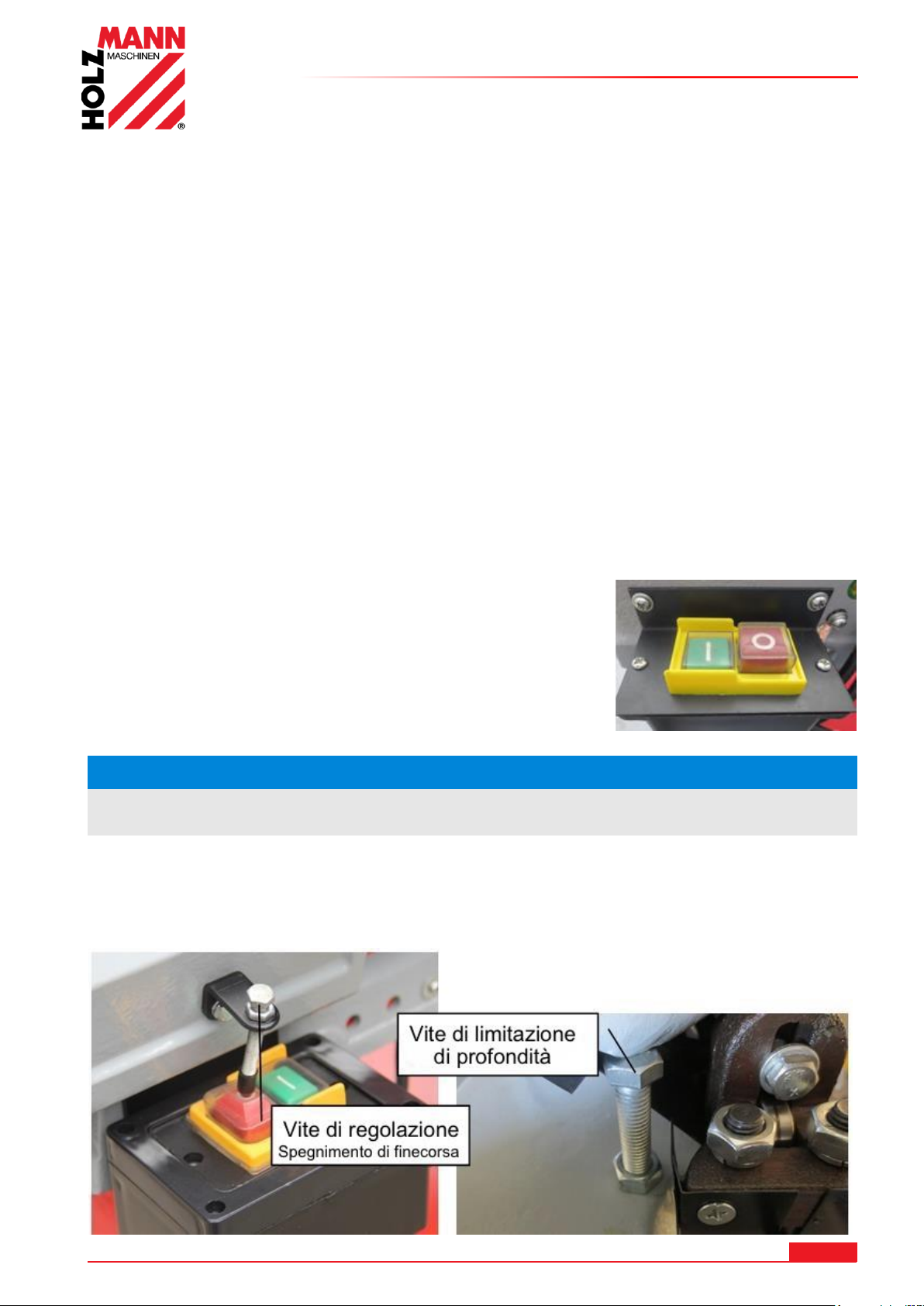
22.3 Uso
NOTA
Prima di iniziare a tagliare, fare avviare al massimo il motore.
22.3.1 Note da osservare prima della messa in funzione:
Prima di iniziare a tagliare, assicurarsi:
- Che tutti i componenti della macchina sono in stato impeccabile
- Di aver impostato la giusta velocità della lama a nastro per il relativo materiale da
tagliare e di utilizzare il tipo di lama giusto
- Che il pezzo in lavorazione è correttamente bloccato con la giusta angolazione
- Che il pezzo in lavorazione ha un appoggio stabile. Pezzi in lavorazione più lunghi devono
essere sorretti da un apposito supporto (ad esempio un carrello da supporto)
- Che la lama a nastro è correttamente regolata (tensione della lama nonché lo scorrimento
verticale)
- Che il braccio di taglio è ruotato verso l’alto e non tocca il pezzo in lavorazione
- Che non ci sono più attrezzi sul banco della macchina
22.3.2 Interruttori ON / OFF
USO
La macchina si accende premendo il pulsante verde ON e si spegne premendo il pulsante rosso
OFF.
- Avvicinare il braccio di taglio con la staffa di supporto (3) al
pezzo in lavorazione.
- Lasciare che il braccio di taglio attraversi il materiale sfruttando
il proprio peso.
- - Non esercitare alcuna pressione. Una volta tagliato il
materiale, la sega si spegne automaticamente attivando il
pulsante OFF.
Una volta raggiunto il livello di taglio più basso, la macchina si spegne automaticamente attivando
il pulsante OFF.
Lo spegnimento automatico può essere regolato aggiustando la vite del limite di profondità.
HOLZMANN MASCHINEN GmbH www.holzmann-maschinen.at 77
BS115 / BS128HDR
Page 78
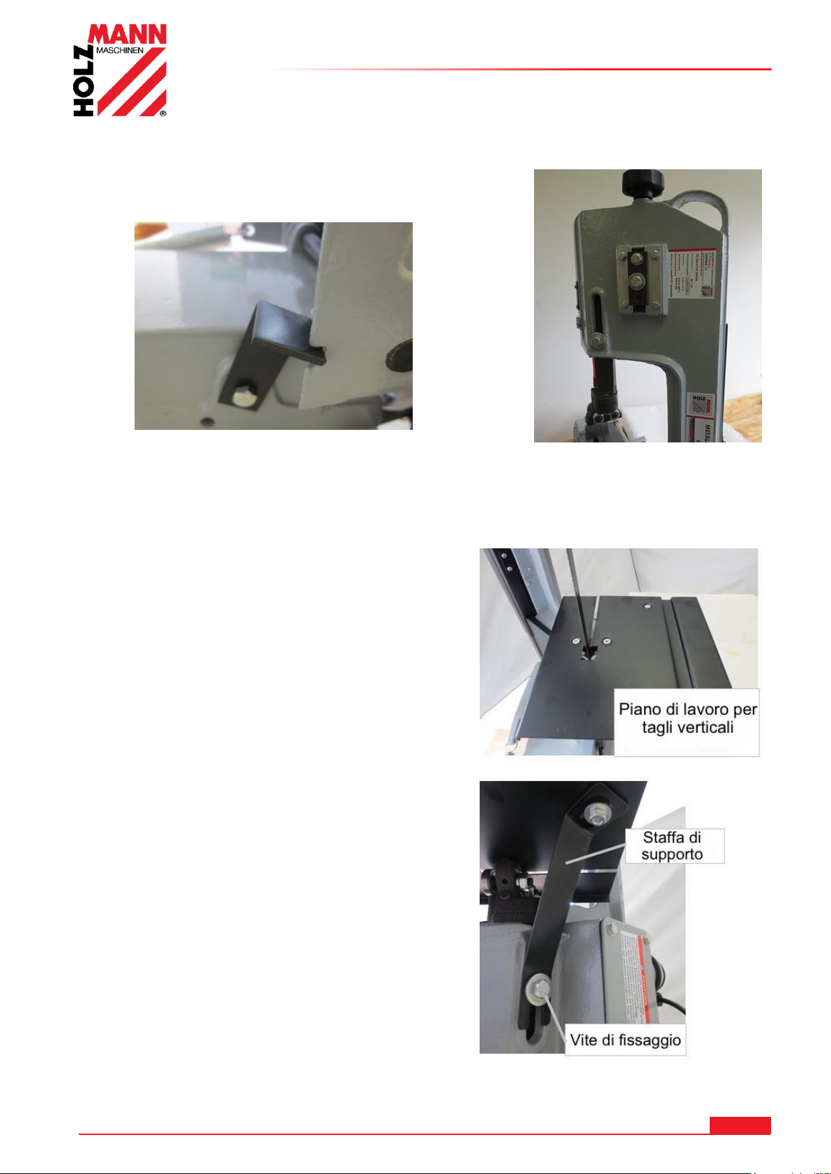
22.3.3 Utilizzare la sega a nastro in posizione verticale
Alzare il braccio della sega a nastro nella posizione
a 90° e fissarlo alla console di base con una staffa
angolare di fissaggio.
Svitare la copertura di protezione.
Avvitare il piano di lavoro alla guida della lama a
nastro con le due viti.
Allentare le viti di fissaggio (12) della guida della
lama a nastro.
Inserire la staffa di supporto in
corrispondenza della vite di fissaggio (12).
Avvitarla al piano di lavoro con la vite a testa
svasata sopra e il dado con la rondella sotto.
La guida della lama a nastro superiore può essere
abbassata allentando la vite di fissaggio (12) e
avvitandola nel secondo foro filettato.
In questo modo la lama a nastro verrà guidata
ancora meglio.
USO
HOLZMANN MASCHINEN GmbH www.holzmann-maschinen.at 78
BS115 / BS128HDR
Page 79
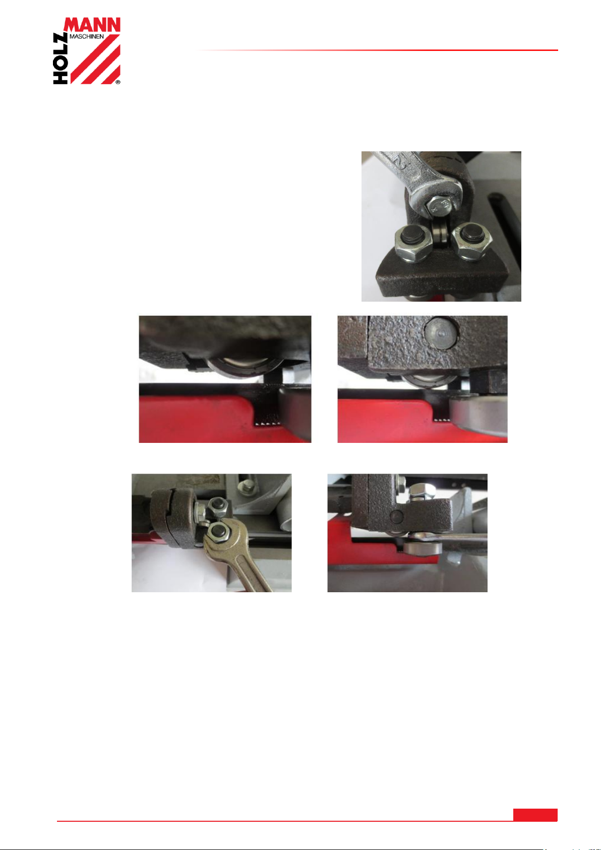
22.4 BS128HDR
Allentare leggermente la guida
della lama a nastro girando la vite
di fissaggio.
Abbassando la guida della lama a nastro con il cuscinetto a rullo sulla stessa si azzera il gioco.
Allentare leggermente i dadi su entrambi i
rulli laterali delle guide con una chiave a
bocca SW17.
Con una chiave a bocca SW 12 e l’aiuto di
una vite dell’eccentrico, il cuscinetto a rullo
viene spostato dall’esterno verso l’interno.
Ripetere la procedura su entrambi i lati finché
non vi è più gioco tra i cuscinetti a rullo.
La lama a nastro dovrebbe essere allineata
centralmente rispetto al cuscinetto a rullo
superiore.
ATTENZIONE: Non serrare troppo i
cuscinetti a rullo laterali sulla lama a nastro!
Una volta regolati i due cuscinetti a rullo, sarà necessario serrare i due dadi sopra gli stessi.
22.4.1 Regolazione guida della lama a nastro verticalmente rispetto al pezzo di taglio
USO
HOLZMANN MASCHINEN GmbH www.holzmann-maschinen.at 79
BS115 / BS128HDR
Page 80
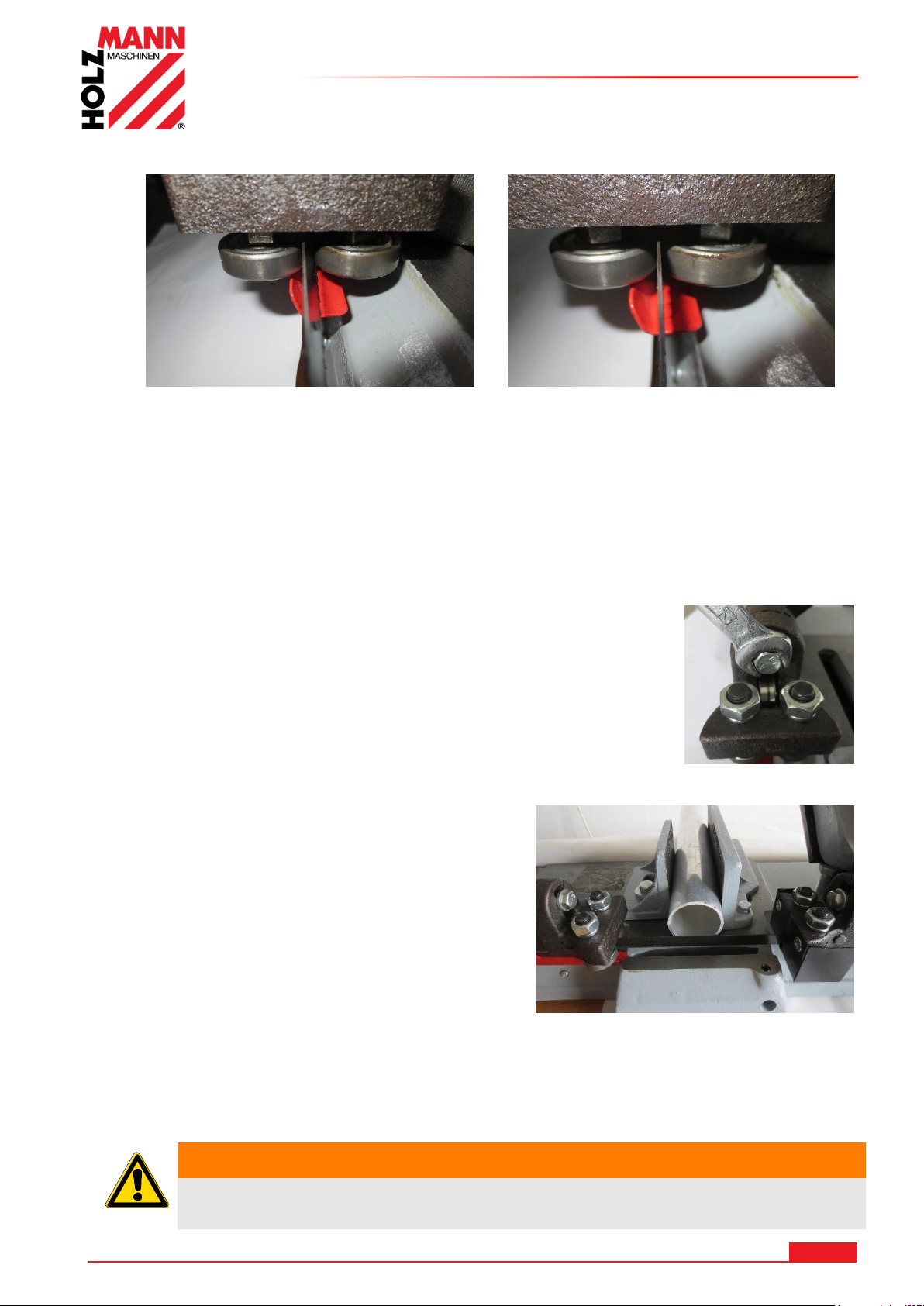
Esempio di una regolazione perfetta della guida della lama a nastro:
La lama a nastro ha ancora troppo gioco e
dunque risulta inclinata tra i cuscinetti a rullo
laterali.
La lama a nastro è quasi senza gioco si
trova in posizione perfettamente verticale
rispetto i cuscinetti a rullo laterali.
AVVERTENZA
Eseguire tutti i lavori di adattamento solo a macchina
scollegata dalla rete elettrica!
USO
Con un calibro angolare oppure in corrispondenza di un pezzo in lavorazione rettangolare,
verificare l’impostazione a 90° della guida della lama a nastro.
Ripetere questa procedura sulla guida della lama a nastro di destra nel caso che la lama a nastro
non dovesse scorrere perfettamente in senso verticale.
Una volta regolata esattamente la lama a nastro, serrare correttamente guida della lama.
NOTA: Avvicinare il più possibile la guida della lama a nastro di destra
e di sinistra al pezzo in lavorazione.
Allentando la vite di serraggio per la guida della
lama a nastro (8), è possibile spostare la guida di
sinistra.
La guida della lama a nastro di destra può essere
spostata allentando la vite.
ATTENZIONE: Tagli inclinati si verificano quando le guide della lama a nastro non
sono esattamente verticali e vi è troppo gioco tra i cuscinetti a rullo
laterali!
HOLZMANN MASCHINEN GmbH www.holzmann-maschinen.at 80
BS115 / BS128HDR
Page 81
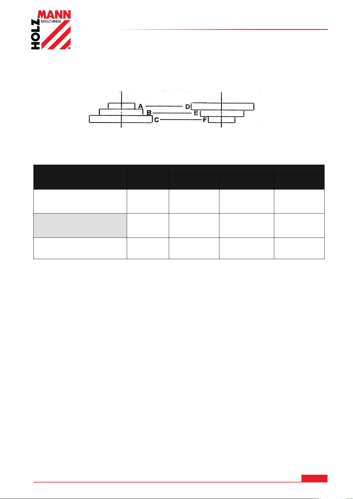
22.4.2 Selezionare la velocità della lama a nastro
Materiale
Velocità
(m/min)
Regolazione cinghia
Puleggia del
motore
Puleggia di
trasmissione
Lama sega a
nastro
Acciaio inox - Nirosta ®
Acciaio per attrezzi - acciaio
legato - bronzina
23 A D
Bimetallo
Acciaio da costruzione ferro acciaio fuso - acciaio
Thomas
34 B E
Bimetallo
Ottone - materiali simili
all’alluminio
54 C F
HS
S
Puleggia del motore
Puleggia motrice
La lama a nastro viene azionata tramite una trasmissione a cinghia. Adeguare la velocità della
lama a nastro al materiale da tagliare.
Regolare l’avanzamento in base alla seguente tabella.
USO
HOLZMANN MASCHINEN GmbH www.holzmann-maschinen.at 81
BS115 / BS128HDR
Page 82
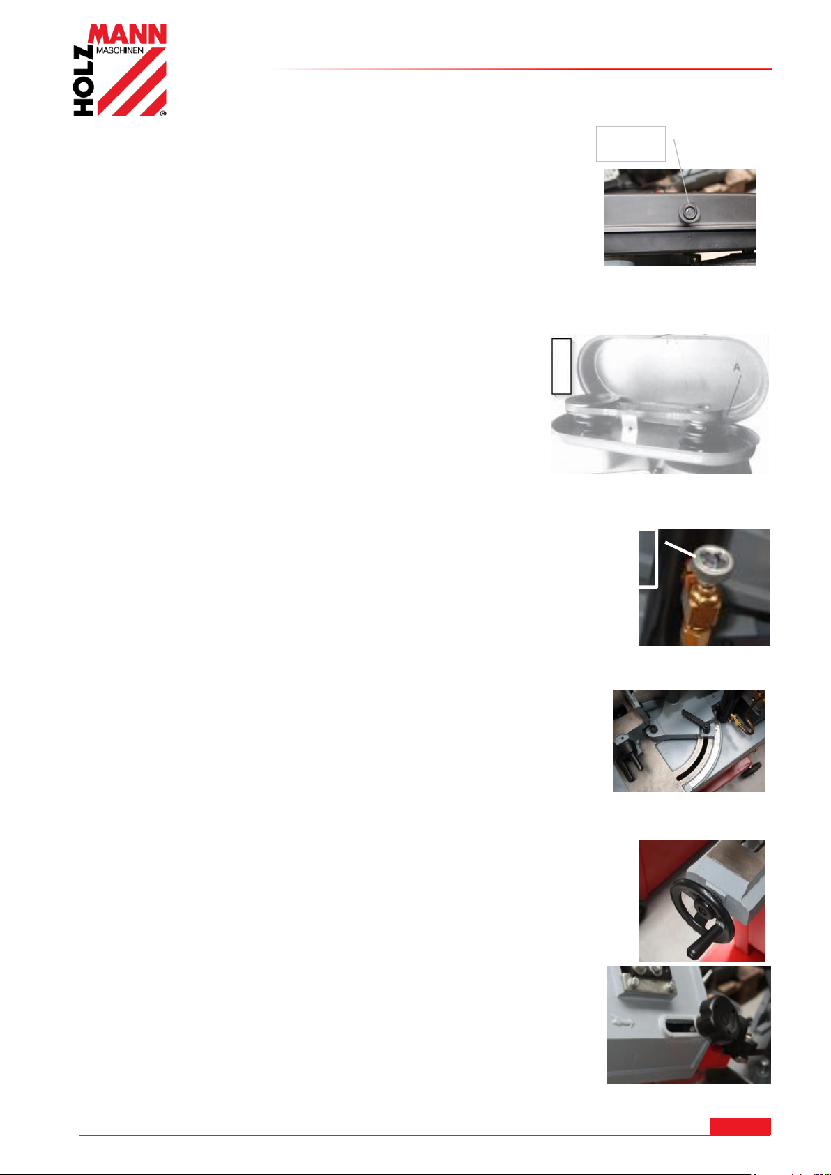
USO
Vite di regolazione
dell’avanzamento
Perno
22.4.3 Regolazione velocità della lama a nastro
Aprire il coperchio tirando l’apposito perno e sollevando il coperchio.
Adesso è possibile impostare la velocità di taglio in base alla tabella dei numeri di giri riportata sul
coperchio.
Ruotare leggermente la puleggia e avvitare la cinghia
trapezoidale nell’apposita scanalatura della puleggia.
ATTENZIONE:
La cinghia trapezoidale deve trovarsi sempre sullo stesso livello
della puleggia opposta.
22.4.4 Regolazione dell’avanzamento
È possibile regolare l’avanzamento tramite la vite di
regolazione sul cilindro di abbassamento (4).
Regolare l’avanzamento in base alla seguente tabella.
22.4.5 Regolazione della squadra zoppa
Allentare la vite di serraggio (5).
Adesso è possibile spostare l’intero braccio.
Stringendo la vite di serraggio (5), lo stesso viene nuovamente
fissato.
22.4.6 Bloccaggio del pezzo in lavorazione
Posizionare il pezzo in lavorazione nella morsa e bloccarlo con l’aiuto della
manovella (7).
22.4.7 Regolazione guida della lama a nastro
Regolare la guida in modo che questa si venga a trovare ca. 2 cm
prima del pezzo in lavorazione.
Allentare la manovella (8) e spostare la guida.
Ristringere la manovella.
HOLZMANN MASCHINEN GmbH www.holzmann-maschinen.at 82
BS115 / BS128HDR
Page 83

USO
Vite di regolazione spegnimento di finecorsa
NOTA
Prima di iniziare a tagliare, fare avviare al massimo il motore.
22.4.8 Regolazione tensione della lama a nastro
Regolare la tensione della lama a nastro (2 - 3 mm test) con la manopola di regolazione (10).
Effettuare un breve giro di prova e, se necessario, tendere di nuovo.
22.4.9 Avviare / arrestare Interruttori ON / OFF:
La macchina si accende premendo il pulsante verde ON e si spegne premendo il pulsante rosso
OFF.
Lo spegnimento automatico può essere regolato
aggiustando la vite dello spegnimento di finecorsa.
- Avvicinare il braccio di taglio con la staffa di
supporto (3) al pezzo in lavorazione.
- Lasciare che il braccio di taglio attraversi il materiale
sfruttando il proprio peso.
- Non esercitare alcuna pressione. Una volta tagliato il
materiale, la sega si spegne automaticamente attivando il
pulsante OFF.
22.4.10 Segare
Accendere la macchina attivando il pulsante
ON / OFF (9).
Rimuovere il perno di fissaggio.
Grazie all’avanzamento automatico, il braccio
di taglio si muove autonomamente verso il
basso.
Non esercitare alcuna pressione.
Una volta tagliato il materiale, la sega si spegne automaticamente attivando il pulsante OFF.
Sollevare il braccio di taglio e rinfilare il perno di fissaggio nell’apposito foro.
LA DENTELLATURA DELLA LAMA A NASTRO DOVREBBE ESSERE ADEGUATA AL
MATERIALE DA TAGLIARE:
1. Più fine / stretto è il pezzo in lavorazione, più alta dovrà essere la dentellatura
2. Regola di base: in ogni momento dovrebbero lavorare almeno 3 denti nel materiale
ATTENZIONE: Quando la sega a nastro per metalli non è stata utilizzata per molto
tempo, allentare la tensione della lama a nastro svitando il pulsante di regolazione per la
tensione della lama (10).
HOLZMANN MASCHINEN GmbH www.holzmann-maschinen.at 83
BS115 / BS128HDR
Page 84
MANUTENZIONE
ATTENZIONE
Prima di effettuare lavori di manutenzione spegnere
la macchina e scollegare il cavo di alimentazione!
Potenziali danni materiali e lesioni gravi dovute
all'accensione accidentale della macchina!
NOTA
Solo un apparecchio sottoposto a manutenzione regolare e ben curato può essere uno
strumento soddisfacente. I difetti di manutenzione e di cura possono causare incidenti e
lesioni imprevedibili.
Le riparazioni che richiedono competenze tecniche specifiche devono essere eseguite
solo dai centri di assistenza autorizzati.
Gli interventi non conformi possono danneggiare l'apparecchio o
comprometterne la sicurezza.
23 MANUTENZIONE
La macchina richiede pochissima manutenzione e contiene solo poche parti che devono essere
soggette a manutenzione.
Anomalie o difetti che possono pregiudicare la sicurezza della macchina, devono essere eliminati
immediatamente.
Controllare regolarmente se sulla macchina sono presenti gli avvertimenti e le avvertenze per la
sicurezza e se sono perfettamente leggibili.
Prima di ogni utilizzo controllare che i dispositivi di sicurezza siano in condizioni perfette!
In caso di stoccaggio della macchina, questa non deve essere conservata in un locale umido e
deve essere protetta dall'influsso degli agenti atmosferici.
Prima della prima messa in funzione, lubrificare tutti i collegamenti mobili con un sottile strato di
olio o grasso.
23.1 Manutenzione e piano di manutenzione
Dopo ogni messa in servizio:
Portare il braccio di taglio nella posizione più alta e bloccarlo.
Allentare la tensione sulla lama a nastro.
Pulire la macchina interamente.
Lubrificare le superfici di scorrimento della morsa e la guida dalla lama a nastro con un
leggero olio per macchine.
Dopo 50 ore di esercizio
Lubrificare tutti i collegamenti mobili (se necessario pulirli prima da trucioli e polvere con una
spazzola) con un sottile strato di olio o grasso
HOLZMANN MASCHINEN GmbH www.holzmann-maschinen.at 84
BS115 / BS128HDR
Page 85
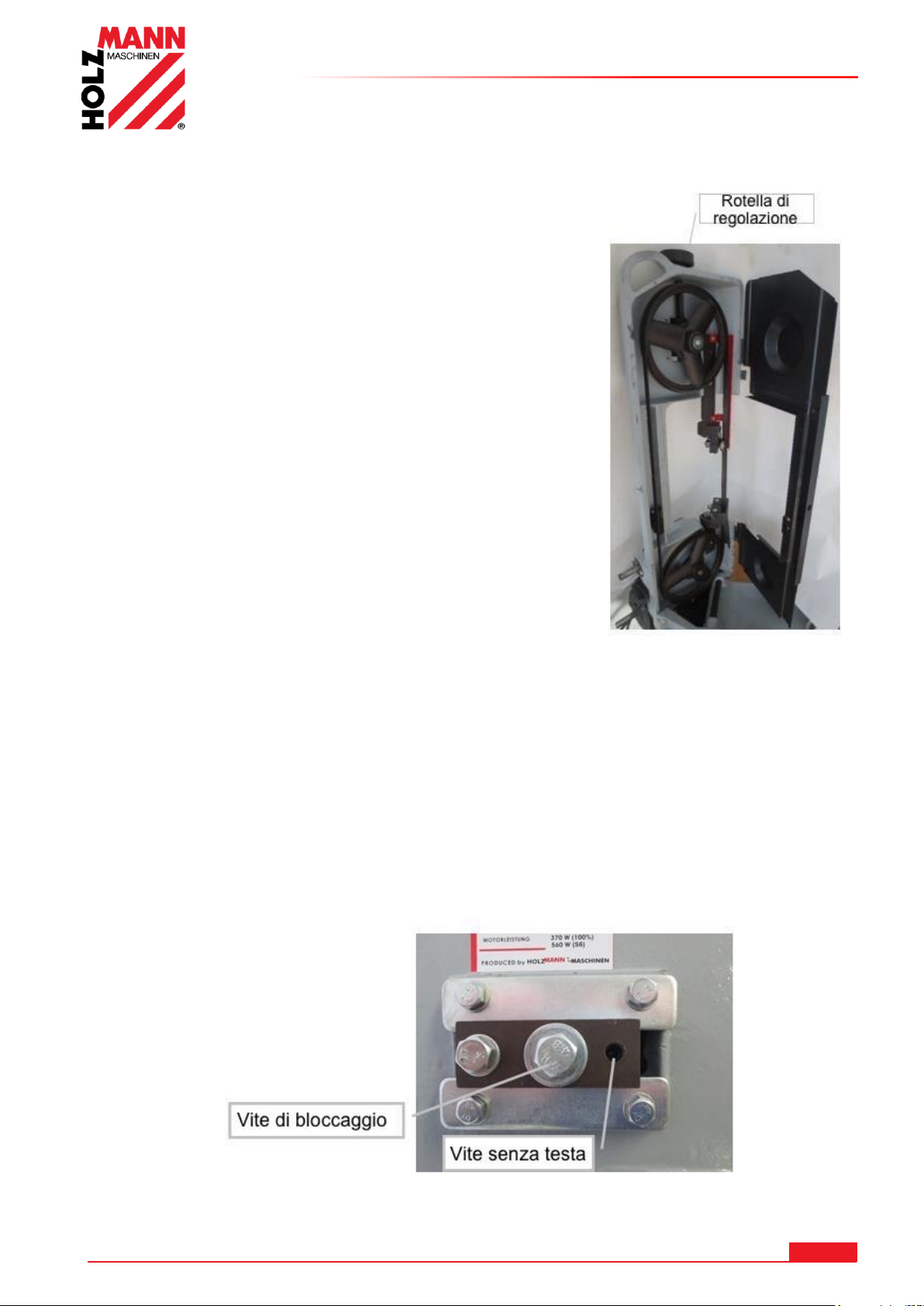
23.2 Sostituzione della lama
Portare la sega a nastro per metalli in posizione verticale e
aprire la copertura della lama a nastro.
Allentare la lama a nastro con il pomello di regolazione (10).
Svitare la parte alta della lamiera di protezione della
lama a nastro sulla guida della lama.
Rimuovere la vecchia lama a nastro dai giranti.
ATTENZIONE! Pericolo di lesioni!
Indossare sempre guanti da lavoro.
Inserire dapprima la lama a nastro nelle guide e
successivamente sui giranti.
ATTENZIONE: Fare attenzione al giusto senso di
rotazione della dentellatura della lama a nastro (vedi
illustrazione davanti a sinistra del braccio di taglio) e
successivamente inserirla sui giranti.
Regolare la tensione della lama a nastro (1 mm test) con la
manopola di regolazione (10).
Dopo un breve giro di prova, ricontrollare la tensione, lo
scorrimento e l’inclinazione della lama ed eventualmente
correggerli in base.
Riavvitare la lamiera di protezione della lama a nastro.
Riavvitare entrambe le coperture della lama a nastro
MANUTENZIONE
23.3 Regolazione scorrimento e inclinazione della lama a nastro
Di fabbrica il girante è allineato alla ruota motrice. Nel caso però, soprattutto dopo la
sostituzione, la lama a nastro non dovesse scorrere dritta o scivolare dal girante, potrebbe essere
necessaria una correzione.
È possibile correggere lo scorrimento e l’inclinazione.
Allentare leggermente la vite di serraggio.
È possibile correggere lo scorrimento del nastro grazie alla vite senza testa.
Riavvitare la vite di serraggio.
HOLZMANN MASCHINEN GmbH www.holzmann-maschinen.at 85
BS115 / BS128HDR
Page 86
MANUTENZIONE
NOTA
L'uso di solventi, prodotti chimici aggressivi o prodotti
abrasivi causa danni materiali alla macchina!
Pertanto vale la regola: Durante la pulizia usare solo acqua e se
necessario detergenti delicati!
23.4 Lubrificazione
Non è necessario lubrificare i cuscinetti a sfera.
Lubrificare il perno filettato della ganascia di serraggio all’occorrenza
Applicare un sottile strato di olio per macchine su tutte le superfici laccate.
L’ingranaggio si muove in un bagno d’olio e necessita di un cambio dell’olio completo ca. 1 volta
all’anno: Per fare ciò, portare il braccio di taglio in posizione orizzontale
Svitare le quattro viti dalla protezione del motore e rimuovere la copertura.
Posizionare un contenitore di accumulo sotto alla scatola degli ingranaggi. Sollevare il braccio di
taglio in modo da far defluire l’olio.
Pulire la scatola degli ingranaggi dai residui di olio grezzi, versare l’OLIO PER GLI INGRANAGGI
nuovo, rimontare con accuratezza la copertura.
Smaltire l’olio usato in maniera ecologicamente sostenibile.
23.5 Pulizia
Dopo ogni messa in servizio la macchina e tutte le componenti devono essere pulite a fondo.
Liberare la macchina da trucioli e polvere di foratura con regolarità una volta terminato il lavoro.
Impregnare le superfici nude della macchina con i comuni prodotti anti-corrosione.
23.6 Smaltimento
Non smaltire la macchina nei rifiuti non riciclabili. Contattare le autorità locali per
informazioni sulle opzioni di smaltimento disponibili. Quando si acquista una nuova
macchina o un apparecchio equivalente dal rivenditore, questo è obbligato a smaltire il
vecchio apparecchio.
HOLZMANN MASCHINEN GmbH www.holzmann-maschinen.at 86
BS115 / BS128HDR
Page 87
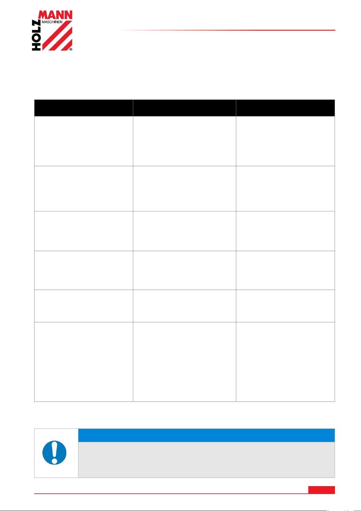
RIMEDI IN CASO DI ANOMALIE
Errore
Possibili cause
Soluzion
e
La macchina non parte
La macchina non
è collegata
Fusibile o relè guasto
Cavo danneggiato
Controllare tutti i
collegamenti elettrici
Sostituire il
fusibile, attivare il
relé
Sostituire il cavo
La lama non prende
velocità
Cavo prolunga troppo lungo
Motore non adatto alla
tensione presente
Rete elettrica debole
Sostituire con cavo di
prolunga adatto
Vedere copertura
Contattare
l'elettricista
Il motore si riscalda molto
velocemente
Il motore su una o più
fasi non riceve
abbastanza corrente
Contattare
l'elettricista
Non coperto da
garanzia. Errore sulla
rete.
La lama scorre nella
direzione inversa
Fasi invertite
Contattare
l'elettricista
Non coperto da
garanzia. Errore sulla
rete.
La macchina vibra molto
È su un fondo irregolare
Fissaggio motore allentato
Ri-allineare
Stringere le viti di
fermo
Tagli scadenti
Velocità di abbassamento
troppo alta
Lama non idonea
Lama spuntata
Lama allentata
Guida della lama a nastro
spostata
Impostare una velocità
di abbassamento più
bassa
Per metalli duri,
utilizzare una
lama a nastro BI
Sostituire la lama
Tendere la lama
Correggere la guida
della lama a nastro
NOTA
Se, qualora vi fosse l'esigenza di effettuare delle riparazioni, voi
non vi sentite in grado di farle, o non disponete della necessaria
formazione, rivolgetevi sempre a un'officina specializzata per
risolvere il problema.
24 RIMEDI IN CASO DI ANOMALIE
PRIMA DI INIZIARE A LAVORARE PER ELIMINARE I DIFETTI, SCOLLEGARE LA
MACCHINA DALL'ALIMENTAZIONE DI CORRENTE.
SI POSSONO ESCLUDERE A PRIORI MOLTE FONTI POTENZIALI DI DIFETTI
CALLACCIANDOSI CORRETTAMENTE ALLA RETE DI ALIMENTAZIONE.
HOLZMANN MASCHINEN GmbH www.holzmann-maschinen.at 87
BS115 / BS128HDR
Page 88
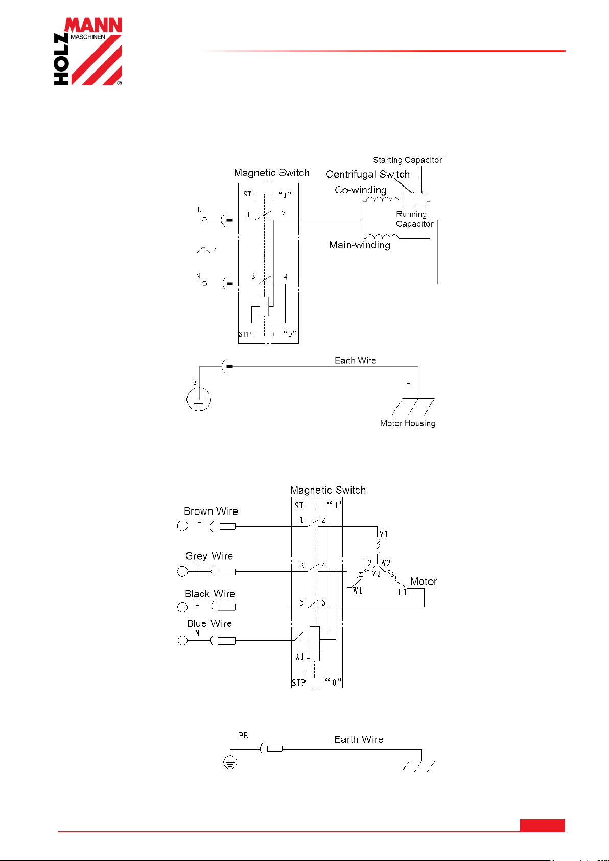
25 SCHALTPLAN / WIRING DIAGRAM
25.1 230V
SCHALTPLAN / WIRING DIAGRAM
25.2 400V
HOLZMANN MASCHINEN GmbH www.holzmann-maschinen.at 88
BS115 / BS128HDR
Page 89

ERSATZTEILE / SPARE PARTS
HI NW EI S
Der Einbau von anderen als Originalersatzteilen führt zum Verlust der Garantie!
Daher gilt: Beim Tausch von Komponenten/Teilen nur Originalersatzteile verwenden
IM PO RT AN T
The installation of other than original spare parts voids the warranty!
So you always have to use original spare parts
NO TA
Il montaggio di altre parti di ricambio originali causa la perdita della garanzia!
Pertanto vale la regola: Quando si sostituiscono componenti/pezzi utilizzare solo parti di ricambio
originali
26 ERSATZTEILE / SPARE PARTS
26.1 Ersatzteilbestellung / spare parts order
Mit HOLZMANN-Ersatzteilen verwenden Sie Ersatzteile, die ideal aufeinander abgestimmt sind. Die optimale
Passgenauigkeit der Teile verkürzen die Einbauzeiten und erhöhen die Lebensdauer.
Beim Bestellen von Ersatzteilen verwenden Sie bitte das Serviceformular, das Sie am Ende dieser Anleitung
finden. Geben Sie stets Maschinentype, Ersatzteilnummer sowie Bezeichnung an. Um Missverständnissen
vorzubeugen, empfehlen wir mit der Ersatzteilbestellung eine Kopie der Ersatzteilzeichnung beizulegen, auf
der die benötigten Ersatzteile eindeutig markiert sind.
Bestelladresse sehen Sie unter Kundendienstadressen im Vorwort dieser Dokumentation.
With original HOLZMANN spare parts you use parts that are attuned to each other shorten the installation time
and elongate your products lifespan.
When you place a spare parts order please use the service form you can find in the last chapter of this manual.
Always take a note of the machine type, spare parts number and part name. We recommend to copy the spare
parts diagram and mark the spare part you need.
You find the order address in the preface of this operation manual.
Con le parti di ricambio Holzmann utilizzate pezzi di ricambio che combaciano e sono adatti tra loro. L'esattezza
di adattamento ottimale dei pezzi accorcia i tempi di montaggio e mantiene la durata di vita.
Per ordinare parti di ricambio usare il modulo dell'assistenza che trovate al termine di queste istruzioni.
Indicare sempre il tipo di macchina, il numero di parte di ricambio e la denominazione. Per evitare
incomprensioni, si raccomanda di allegare agli ordini di parti di ricambio una copia del disegno delle parti di
ricambio, su cui sono evidenziate in modo chiaro le parti di ricambio richieste.
L'indirizzo per gli ordini si trova sotto gli indirizzi dei centri di assistenza clienti nella prefazione di questa
documentazione.
HOLZMANN MASCHINEN GmbH www.holzmann-maschinen.at 89
BS115 / BS128HDR
Page 90
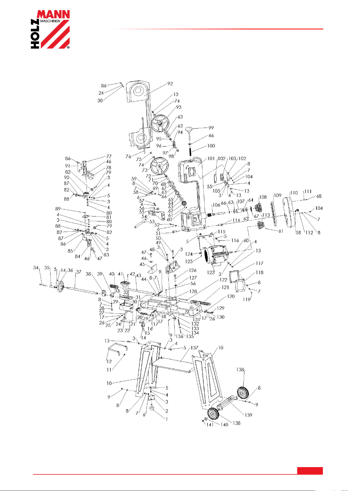
26.2 Explosionszeichnung / explosion drawing
26.2.1 BS 115
ERSATZTEILE / SPARE PARTS
HOLZMANN MASCHINEN GmbH www.holzmann-maschinen.at 90
BS115 / BS128HDR
Page 91
ERSATZTEILE / SPARE PARTS
No.
Part Name
Qty
No.
Part Name
Qty
1
Rubber pad
2
40
Rubber sleeve
1
2
Steel Bracket
4
41
Magnetic switch
1
3
Flat washer
18
42
Screw
2
4
Elastic washer
15
43
Adjusting bar
1
5
Nut
16
44
Fixing plate (A)
1
6
Nut
10
45
Rear clamping plate
1
7
Elastic washer
15
46
Big flat washer
3
8
Flat washer
16
47
Bolt
2
9
Bolt
9
48
Front clamping plate
1
10
Support leg
2
49
Bolt
1
11
Ear ring
2
50
Bolt
1
12
Carrying handle
1
51
Bolt
1
13
Bolt
7
52
Bolt
1
14
Screw
2
53
Turning shaft
1
15
Position block
1
54
Connecting block
1
16
Sliding bar
1
55
Big flat washer
2
17
Flat washer
9
56
Screw
2
18
Locking nut
2
57
Screw
2
19
Bolt
2
58
Screw
1
20
Cable and plug
1
59
Switch pressing bracket
1
21
Strain relief
2
60
Flat pin
1
22
Switch box support bracket
1
61
Screw
1
23
Teeth washer
2
62
Gear wheel
1
24
Elastic washer
7
63
Ball bearing
4
25
Screw
2
64
Oil seal
3
26
Elastic washer
4
65
Gear wheel tube
1
27
Screw
2
66
Retaining ring
1
28
Bolt
2
67
Cover plate
1
29
Switch box
1
68
Screw
6
30
Flat washer
9
69
Bolt
1
31
Screw
4
70
Wheel shaft
1
32
Switch box cover
1
71
Position tube
1
33
Screw
4
72
Flat pin
1
34
Screw
1
73
Drive wheel
1
35
Wheel bar
1
74
Retaining ring
2
36
Turning wheel
1
75
Bolt
1
37
Thread bar
1
76
Blade
1
38
Thread bar nut
1
77
Upper blade guide
1
39
Position holder
1
78
Locking knob
1
79
Pin
1
122
Hook
1
80
Bolt
1
123
Motor
1
81
Blade position plate
1
124
Cable fixing plate
3
82
Ball bearing
6
125
Screw
2
83
Lower blade protection block
1
126
Bolt
1
HOLZMANN MASCHINEN GmbH www.holzmann-maschinen.at 91
BS115 / BS128HDR
Page 92
ERSATZTEILE / SPARE PARTS
84
Lower blade guide
1
127
Nut
1
85
Lower blade protection plate
1
128
Fixing plate (B)
1
86
Screw
3
129
Strain relief
1
87
Eccentric shaft
4
130
Screw
2
88
Ear ring
4
131
Machine bed
1
89
Screw
3
132
Chain ring (A)
1
90
Upper blade protection block
1
133
Chain
1
91
Upper blade protection plate
1
134
Chain ring (B)
1
92
Rear cover
1
135
Position pin
1
93
Driven wheel
1
136
Position plate
1
94
Elevating block
1
137
Support plate
1
95
Position tube
1
138
Transportation wheel
2
96
Elastic pin
1
139
Wheel bracket
1
97
Adjusting block
1
140
Flat washer
2
98
Driven wheel shaft
1
141
Locking nut
2
99
Tension knob
1
100
Tension spring
1
101
Machine body
1
102
Pressing plate
2
103
Sliding block
1
104
Bolt
4
105
Screw
1
106
Worm
1
107
Gear wheel bush
1
108
Spindle wheel
1
109
V-belt
1
110
Pulley cover
1
111
Big flat washer
1
112
Knob
1
113
Motor pulley
1
114
Bolt
1
115
Motor base plate
1
116
Bolt
4
117
Sealing pad
1
118
Gear box cover
1
119
Bolt
4
120
Clamping plate
1
121
Spring
1
HOLZMANN MASCHINEN GmbH www.holzmann-maschinen.at 92
BS115 / BS128HDR
Page 93
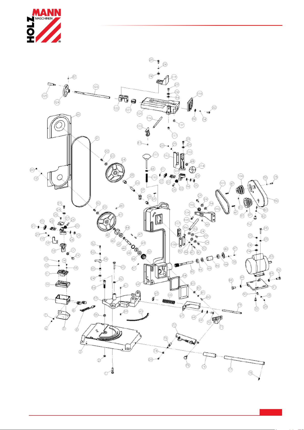
26.2.2 BS 128HDR
ERSATZTEILE / SPARE PARTS
HOLZMANN MASCHINEN GmbH www.holzmann-maschinen.at 93
BS115 / BS128HDR
Page 94
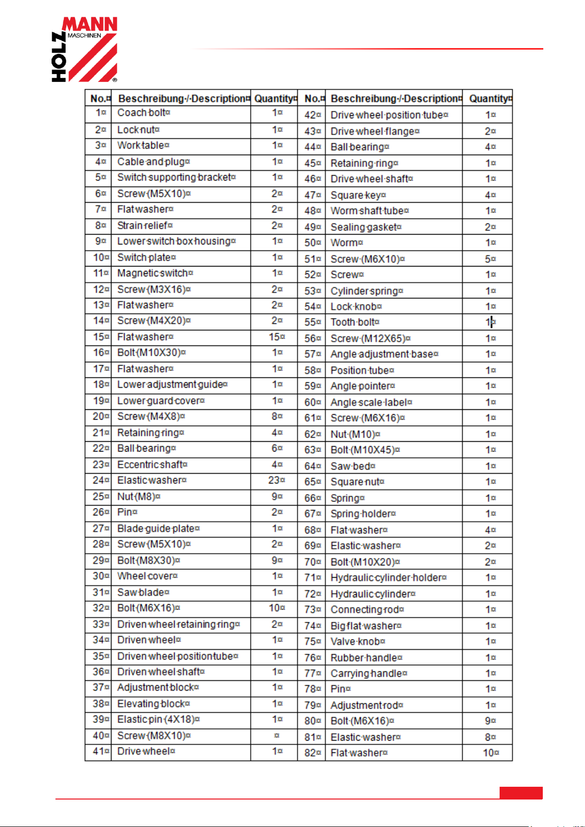
ERSATZTEILE / SPARE PARTS
HOLZMANN MASCHINEN GmbH www.holzmann-maschinen.at 94
BS115 / BS128HDR
Page 95
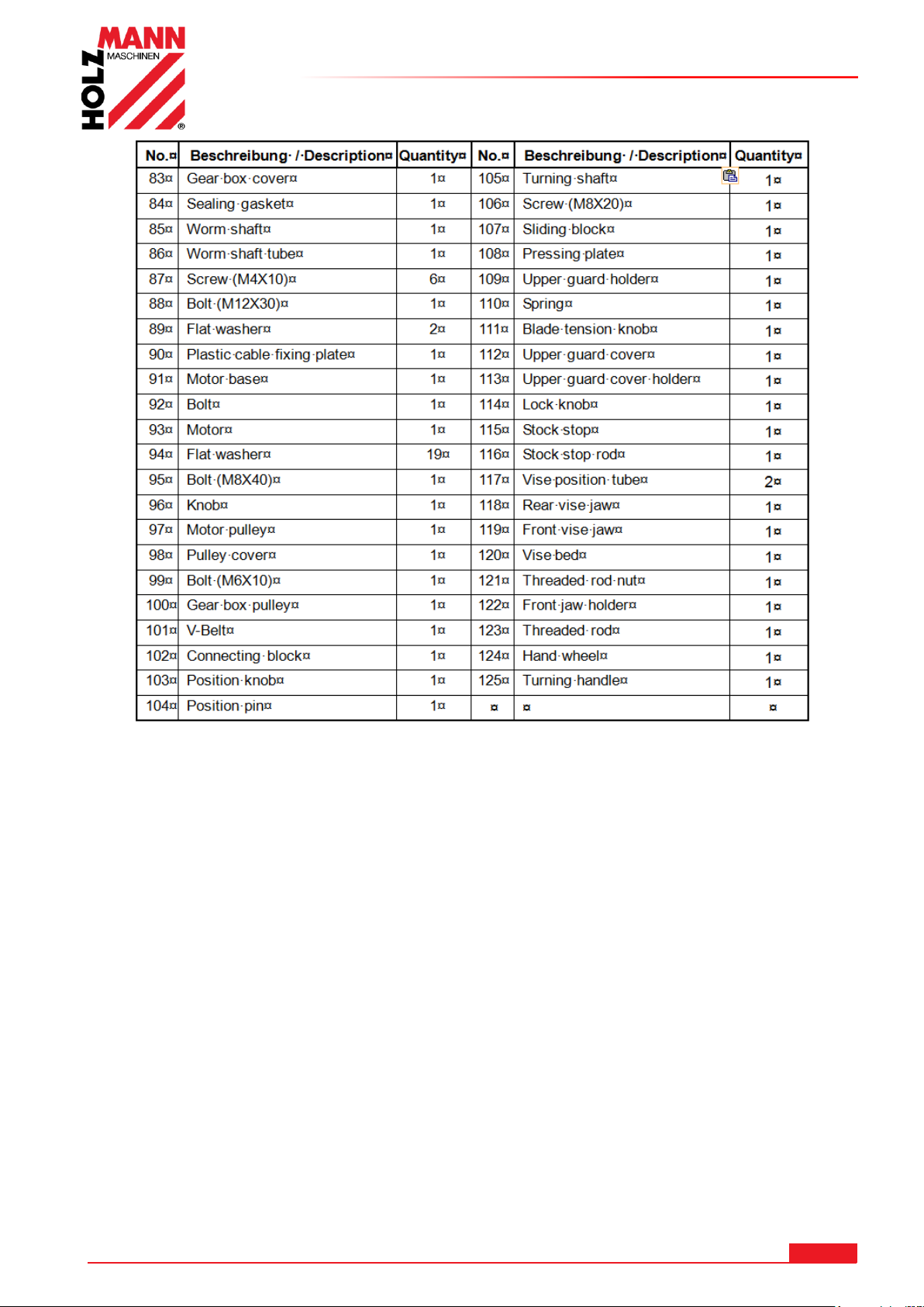
ERSATZTEILE / SPARE PARTS
HOLZMANN MASCHINEN GmbH www.holzmann-maschinen.at 95
BS115 / BS128HDR
Page 96
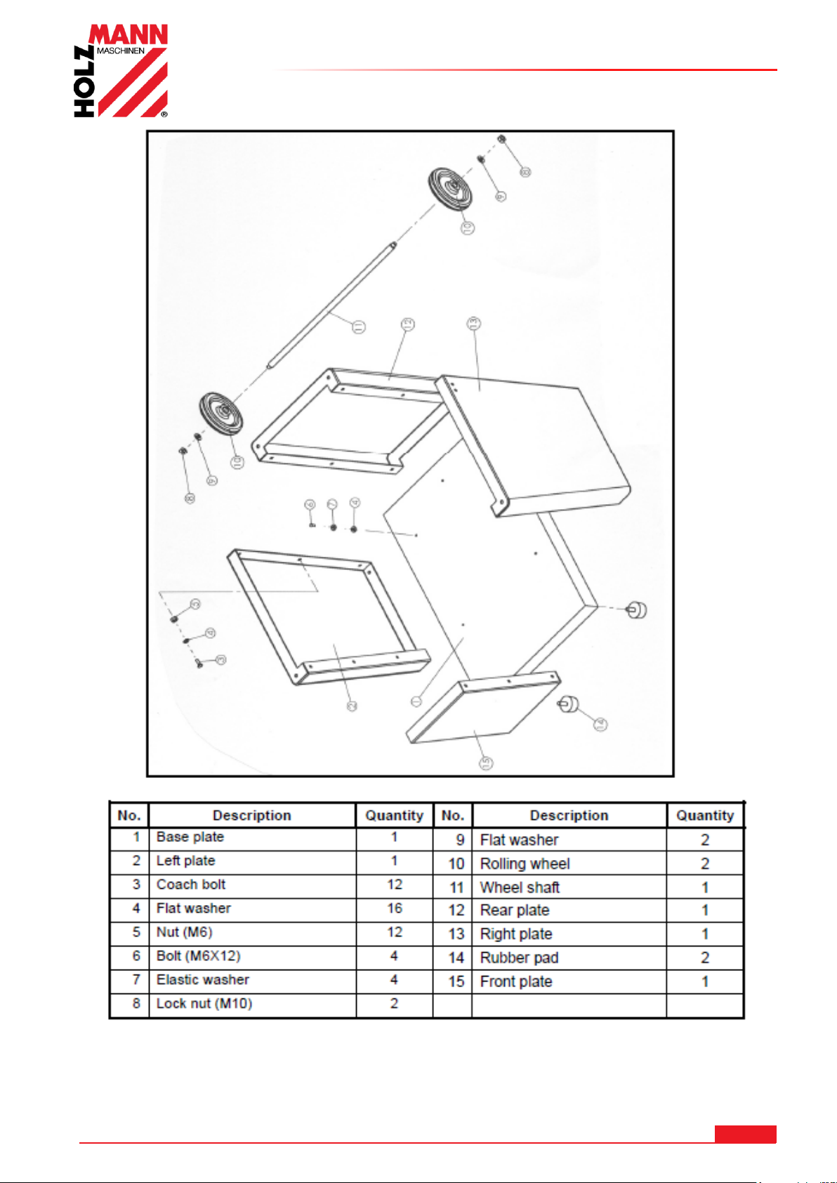
ERSATZTEILE / SPARE PARTS
HOLZMANN MASCHINEN GmbH www.holzmann-maschinen.at 96
BS115 / BS128HDR
Page 97
EU-KONFORMITÄTSERKLÄRUNG/CE-CERTIFICATE OF CONFORMITY
I n v e r k e h r b r i n g e r / D i s t r i b u t o r
HOLZMANN MASCHINEN® GmbH
4170 Haslach, Marktplatz 4, AUSTRIA
Tel.: +43/7289/71562-0; Fax.: +43/7289/71562-4
www.holzmann-maschinen.at
Bezeichnung / name
METALLBANDSÄGE / HEAD BAND SAW
Typ / model
BS 115 / BS 128HDR
EG-Richtlinien / EC-directives
▪2006/42/EG; ▪2014/35/EU,
Angewandte Normen / applicable Standards
EN 13898:2003/A1:2009; EN 60204-1:2006/A1:2009
DI (FH) Daniel Schörgenhuber
Geschäftsführer / Director
27 EU-KONFORMITÄTSERKLÄRUNG/CE-CERTIFICATE OF CONFORMITY
Hiermit erklären wir, dass die oben genannten Maschinen aufgrund ihrer Bauart in der von uns in Verkehr gebrachten Version den
grundlegenden Sicherheits- und Gesundheitsanforderungen der angeführten EU-Richtlinien entsprechen. Diese Erklärung verliert
ihre Gültigkeit, wenn Veränderungen an der Maschine vorgenommen werden, die nicht mit uns abgestimmt wurden.
Hereby we declare that the above mentioned machines meet the essential safety and health requirements of the above stated EC
directives. Any manipulation or change of the machine not being explicitly authorized by us in advance renders this document null
and void.
Con la presente dichiariamo che le macchine sopraindicate, nella versione da noi messa in circolazione, sono conformi nella loro
struttura ai requisiti essenziali di sicurezza e salute delle direttive CE elencate. La presente dichiarazione è nulla se si apportano
modifiche alla macchina che non sono state da noi autorizzate.
Technische Dokumentation
HOLZMANN-MASCHINEN GmbH
4170 Haslach, Marktplatz 4
Haslach, 13.09.2017
Ort / Datum place/date
HOLZMANN MASCHINEN GmbH www.holzmann-maschinen.at 97
BS115 / BS128HDR
Page 98

GARANTIEERKLÄRUNG
28 GARANTIEERKLÄRUNG
1.) Gewährleistung:
HOLZMANN gewährt für elektrische und mechanische Bauteile eine Gewährleistungsfrist von 2 Jahren für den nicht
gewerblichen Einsatz;
bei gewerblichem Einsatz besteht eine Gewährleistung von 1 Jahr, beginnend ab dem Erwerb des Endverbrauchers/Käufers.
HOZMANN weist ausdrücklich darauf hin, dass nicht alle Artikel des Sortiments für den gewerblichen Einsatz bestimmt sind.
Treten innerhalb der oben genannten Fristen/Mängel auf, welche nicht auf im Punkt „Bestimmungen“ angeführten
Ausschlussdetails beruhen, so wird HOLZMANN nach eigenem Ermessen das Gerät reparieren oder ersetzen.
2.) Meldung:
Der Händler meldet schriftlich den aufgetretenen Mangel am Gerät an HOLZMANN. Bei berechtigtem
Gewährleistungsanspruch wird das Gerät beim Händler von HOLZMANN abgeholt oder vom Händler an HOLZMANN gesandt.
Retoursendungen ohne vorheriger Abstimmung mit HOLZMANN werden nicht akzeptiert und können nicht angenommen
werden. Jede Retoursendung muss mit einer von HOLZMANN übermittelten RMA-Nummer versehen werden, da ansonsten
eine Warenannahme und Reklamations- und Retourenbearbeitung durch HOLZMANN nicht möglich ist.
3.) Bestimmungen:
a) Gewährleistungsansprüche werden nur akzeptiert, wenn zusammen mit dem Gerät eine Kopie der Originalrechnung oder
des Kassenbeleges vom Holzmann Handelspartner beigelegt ist. Es erlischt der Anspruch auf Gewährleistung, wenn das
Gerät nicht komplett mit allen Zubehörteilen zur Abholung gemeldet wird.
b) Die Gewährleistung schließt eine kostenlose Überprüfung, Wartung, Inspektion oder Servicearbeiten am Gerät aus.
Defekte aufgrund einer unsachgemäßen Benutzung durch den Endanwender oder dessen Händler werden ebenfalls nicht
als Gewährleistungsanspruch akzeptiert.
c) Ausgeschlossen sind Defekte an Verschleißteilen wie z. B. Kohlebürsten, Fangsäcke, Messer, Walzen, Schneideplatten,
Schneideeinrichtungen, Führungen, Kupplungen, Dichtungen, Laufräder, Sageblätter, Hydrauliköle, Ölfiltern, Gleitbacken,
Schalter, Riemen, usw.
d) Ausgeschlossen sind Schäden an den Geräten, welche durch unsachgemäße Verwendung, durch Fehlgebrauch des
Gerätes ( nicht seinem normalen Verwendungszweckes entsprechend ) oder durch Nichtbeachtung der Bedienungs- und
Wartungsanleitungen, oder höhere Gewalt, durch unsachgemäße Reparaturen oder technische Änderungen durch nicht
autorisierte Werkstätten oder den Geschäftspartnern selbst, durch die Verwendung von nicht originalen HOLZMANN Ersatzoder Zubehörteilen, verursacht sind.
e) Entstandene Kosten (Frachtkosten) und Aufwendungen (Prüfkosten) bei nichtberechtigten Gewährleistungsansprüchen
werden nach Überprüfung unseres Fachpersonals dem Geschäftspartnern oder Händler in Rechnung gestellt.
f) Geräte außerhalb der Gewährleistungsfrist: Reparatur erfolgt nur nach Vorauskasse oder Händlerrechnung gemäß des
Kostenvoranschlages (inklusive Frachtkosten) der Fa. HOLZMANN.
g) Gewährleistungsansprüche werden nur für den Geschäftspartnern eines HOLZMANN Händlers, welcher das Gerät direkt
bei der Fa. HOLZMANN erworben hat, gewährt. Diese Ansprüche sind bei mehrfacher Veräußerung des Gerätes
nicht übertragbar
4.) Schadensersatzansprüche und sonstige Haftungen:
Die Fa. Holzmann haftet in allen Fällen nur beschränkt auf den Warenwert des Gerätes. Schadensersatzansprüche
aufgrund schlechter Leistung, Mängel, sowie Folgeschäden oder Verdienstausfälle wegen eines Defektes während der
Gewährleistungsfrist werden nicht anerkannt. Die Fa. Holzmann besteht auf das gesetzliche Nachbesserungsrecht eines
Gerätes.
SERVICE
Nach Ablauf der Garantiezeit können Instandsetzungs- und Reparaturarbeiten von entsprechend geeigneten Fachfirmen
durchgeführt werden. Es steht Ihnen auch die HOLZMANN-Maschinen GmbH weiterhin gerne mit Service und Reparatur zur
Seite. Stellen Sie in diesem Fall eine unverbindliche Kostenanfrage, unter Angabe der Informationen siehe C) an unseren
Kundendienst oder senden Sie uns Ihre Anfrage einfach per umseitig beiliegendem Formular ein.
Mail: [email protected]
FAX: +43 7289 71562 4
HOLZMANN MASCHINEN GmbH www.holzmann-maschinen.at 98
BS115 / BS128HDR
Page 99

GUARANTEE TERMS
29 GUARANTEE TERMS
1.) Warranty:
For mechanical and electrical components Company Holzmann Maschinen GmbH garants a warranty period of 2 years for
DIY use and a warranty period of 1 year for professional/industrial use - starting with the purchase of the final consumer
(invoice date).
In case of defects during this period which are not excluded by paragraph 3, Holzmann will repair or replace the machine
at its own discretion.
2.) Report:
In order to check the legitimacy of warranty claims, the final consumer must contact his dealer. The dealer has to report in
written form the occurred defect to Holzmann. If the warranty claim is legitimate, Holzmann will pick up the defective
machine from the dealer. Returned shippings by dealers which have not been coordinated with Holzmann will not be
accepted. A RMA number is an absolute must-have for us - we won‘t accept returned goods without an RMA number!
3.) Regulations:
a) Warranty claims will only be accepted when a copy of the original invoice or cash voucher from the trading partner of
Holzmann is enclosed to the machine. The warranty claim expires if the accessories belonging to the machine are missing.
b) The warranty does not include free checking, maintenance, inspection or service works on the machine. Defects due to
incorrect usage through the final consumer or his dealer will not be accepted as warranty claims either.
c) Excluded are defects on wearing parts such as carbon brushes, fangers, knives, rollers, cutting plates, cutting devices,
guides, couplings, seals, impellers, blades, hydraulic oils, oil filters, sliding jaws, switches, belts, etc.
d) Also excluded are damages on the machine caused by incorrect or inappropriate usage, if it was used for a purpose which
the machine is not supposed to, ignoring the user manual, force majeure, repairs or technical manipulations by not
authorized workshops or by the customer himself, usage of non-original Holzmann spare parts or accessories.
e) After inspection by our qualified staff, resulted costs (like freight charges) and expenses for not legitimated warranty
claims will be charged to the final customer or dealer.
f) In case of defective machines outside the warranty period, we will only repair after advance payment or dealer’s invoice
according to the cost estimate (incl. freight costs) of Holzmann.
g) Warranty claims can only be granted for customers of an authorized Holzmann dealer who directly purchased the machine
from Holzmann. These claims are not transferable in case of multiple sales of the machine.
4.) Claims for compensation and other liabilities:
The liability of company Holzmann is limited to the value of goods in all cases.
Claims for compensation because of poor performance, lacks, damages or
loss of earnings due to defects during the warranty period will not be accepted.
Holzmann insists on its right to subsequent improvement of the machine.
SERVICE
After Guarantee and warranty expiration specialist repair shops can perform maintenance and repair jobs. But we are still
at your service as well with spare parts and/or product service. Place your spare part / repair service cost inquiry by filing
the SERVICE form on the following page and send it:
via Mail to [email protected]
or via Fax to: +43 7289 71562 4
HOLZMANN MASCHINEN GmbH www.holzmann-maschinen.at 99
BS115 / BS128HDR
Page 100

DICHIARAZIONE DI GARANZIA
30 DICHIARAZIONE DI GARANZIA
Non vengono toccati da questa dichiarazione di garanzia i diritti di garanzia per vizi della cosa dell'acquirente in forza del
contratto di vendita nei confronti del venditore (distributori Holzmann), nonché i diritti di garanzia previsti dalla legge del
paese in questione.
Per questa macchina si fornisce garanzia alle seguenti condizioni:
A) La garanzia copre l'eliminazione gratuita di tutti i difetti della macchina, in linea con le seguenti regole (B-G), che
pregiudicano il regolare funzionamento della macchina e si fondano su difetti materiali o di produzione.
B) Il periodo di garanzia è di 24 mesi, 12 mesi in caso di uso industriale, valido dalla consegna della macchina al primo
acquirente finale. Come prova fa fede la ricevuta di consegna originale, in caso di ritiro personale della macchina lo
scontrino di acquisto originale.
C) Per notificare diritti di garanzia, contattare il distributore HOLZMANN, da cui avete acquistato la macchina, con la
seguente documentazione:
>> Scontrino di acquisto e/o ricevuta di consegna
>> Modulo assistenza compilato con rapporto di errore
>> In caso di richiesta di parti di ricambio una copia del disegno delle parti di ricambio, con contrassegnati i pezzi di
ricambio richiesti.
D) La gestione della garanzia e il luogo di adempimento della garanzia avviene in conformità con HOLZMANN GmbH. I
difetti di facile eliminazione vengono risolti dai nostri partner distributori, in caso di difetti complessi ci riserviamo di
effettuare una perizia a 4170 Haslach, Austria. Se non viene espressamente stipulato un contratto aggiuntivo di
assistenza in loco, si considera sempre come il luogo di adempimento della garanzia la HOLZMANN MASCHINEN con
sede legale a 4170 Haslach, Austria. I costi di trasporto per la gestione della garanzia dalla e verso la sede aziendale
non sono contemplati nella presente garanzia del produttore.
E) Esclusione di garanzia in caso di difetti:
- sulle componenti meccaniche, che sono soggette a usura legata all'uso o altra usura naturale e difetti alla macchina
riconducibili a usura legata all'uso o altra usura naturale.
- che sono riconducibili a montaggio, messa in servizio o allacciamento alla rete elettrica impropri o negligenti.
- che sono riconducibili a inosservanza delle istruzioni per l'uso, uso improprio, atipiche condizioni ambientali,
condizioni operative estranee al settore e campo di utilizzo, mancata o errata manutenzione o cura.
- che sono causati da utilizzo e montaggio di accessori, parti di ricambio, integrative, che non sono parti di ricambio
originali HOLZMANN.
- che costituiscono differenze minime rispetto alla condizione richiesta, che sono irrilevanti per il valore o l'idoneità
d'uso della macchina.
- che sono riconducibili a un sovraccarico negligente derivante dalle caratteristiche di costruzione. In particolare in
caso di difetti dovuti a utilizzo, che sono classificabili come industriali per livello di sollecitazione ed entità, in caso
di macchine che per costruzione e prestazioni non sono progettate e destinate all'uso industriale.
F) Nell'ambito della presente garanzia si escludono ulteriori diritti dell'acquirente sulle prestazioni di garanzia qui
espressamente citate.
G) Questa garanzia del produttore viene messa in atto volontariamente. Le prestazioni in garanzia non causano
pertanto alcun prolungamento del termine di garanzia e non innescano alcun nuovo termine, nemmeno per le parti di
ricambio.
ASSISTENZA
Trascorso il periodo di garanzia i lavori di manutenzione e riparazione possono essere eseguiti da ditte specializzate
opportune. Anche la HOLZMANN-Maschinen GbmH continua a essere a vostra disposizione per l'assistenza e le riparazioni.
In tal caso inoltrate una richiesta di preventivo senza impegno, indicando le informazioni come da punto C) al nostro servizio
assistenza clienti o inviateci semplicemente la vostra richiesta tramite il modulo allegato.
Mail: [email protected]
FAX: +43 (0) 7289 71562 4
HOLZMANN MASCHINEN GmbH www.holzmann-maschinen.at 100
BS115 / BS128HDR
 Loading...