

i
Product User Manual
Registered info
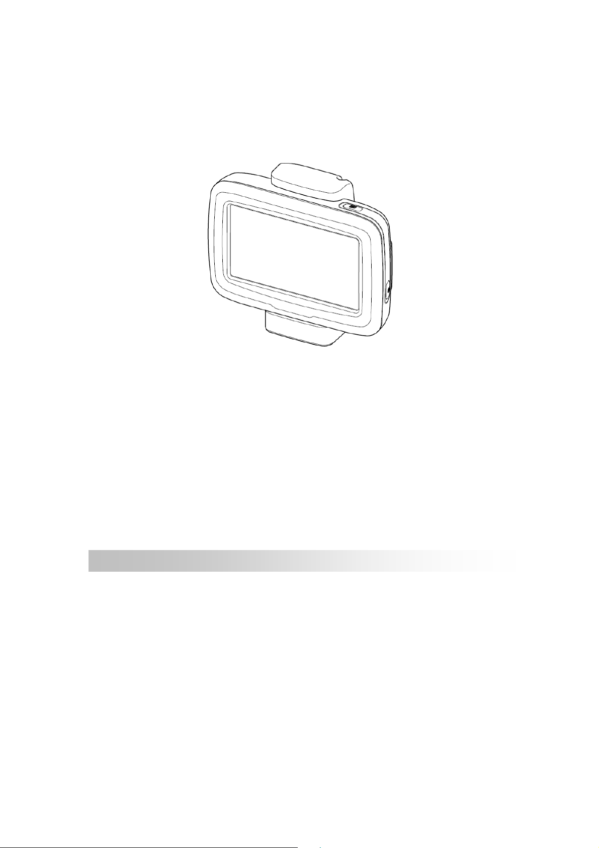
GPSmile 61CS
Navigation System
HOLUX and GPSmile are trademarks of HOLUX Technology, Inc.
All other trademarks belong to registered companies.
Note
The contents of this manual will be modified without further notice.
The operation temperature for the product is between -10℃~50℃.
Operating or recharging in an environment with a temperature
over 50℃ might cause the system to malfunction. However, this
should be considered a normal phenomenon. Please do not
operate under

i
Safety Precautions
The device should only be used with the supplied batteries.
About the battery
1. A Lithium battery is built into the device. To prevent fire or skin
burns, do not disassemble, pierce, impact, or expose the battery to
fire. The battery will crack, explode, or release dangerous
chemicals if placed in a fire.
Important instructions
1. Note: Replacing with an incorrect battery may result in an explosion.
When disposing of the battery, follow the instructions. The
replacement battery must be a factory approved original.
2. Regulations must be observed when recycling or disposing of
batteries.
3. The battery should only be used in this device.
i

i
Warranty Statement
This warranty applies to parts and services that are manufactured and
sold through Holux Technology Inc. The local area covered is Taiwan;
the warranty length is one year from date of purchase (starting from the
date on the sales receipt). Under normal user operation, Holux
Technology provides free repair services.
After repair, the replaced parts are the properties of Holux
Technology Inc.
Holux Technology is not responsible for providing repairs or
replacements of any software; Holux Technology does not provide any
warranty service for third party software/hardware.
Important instructions
Note: This warranty does not cover damage or malfunction from the
below causes: unauthorized disassembly/modification of unit, abuse or
incorrect usage, accidental and other unpreventable causes, operation
under variables mentioned that are different from those in this product
user manual, using parts not made or sold by Holux Technology, or
repairs done by anyone other than Holux Technology and authorized
retail/service providers.
Expendable parts are not covered in the warranty.
Holux Technology is not responsible for any program, data, or
portable storage media damages or loss. Please contact your
local Holux Technology authorized service provider to learn more
about geographical limitations, proof of purchase requests,
response time agreements, and other specific maintenance
service requests.
ii

Technical Support
If there are any questions regarding the use of this product, please
log on to the website www.holux.com and see the FAQ.
Maintenance Service
HOLUX Technology, Inc.
+886-3-6687000
Web Site: www.holux.com
or
Contact your nearest dealer, for further support.
HOLUX Technology, Inc.
www.holux.com
iv

Table of Contents
Safety Precautions ............................................................................. ii
Warranty Statement .......................................................................... iii
Technical Support ............................................................................. iv
Maintenance Service ......................................................................... iv
Preface ............................................................................................... 1
Precautions and Notices ..................................................................... 1
Copyright ....................................................................................... 2
Important Notice ............................................................................ 2
Product Specification ......................................................................... 3
Tools .............................................................................................. 5
Bluetooth Profile support ............................................................... 5
CE/FCC ......................................................................................... 6
First time use ..................................................................................... 7
Package Contents........................................................................... 7
Motorbike RAM Mount Accessory ............................................... 8
Basic Operation ................................................................................. 9
Introduction ................................................................................... 9
Front View .......................................................................................... 9
Rear View ........................................................................................... 9
Accessories .................................................................................. 10
Cradle ................................................................................................ 10
Getting Started ................................................................................. 11
Install Cradle ............................................................................... 11

Remove Cradle ............................................................................ 13
Install motorcycle RAM mount ................................................... 14
Install/ Remove Battery ..................................................................... 19
Device connection Diagram ........................................................ 20

Preface
We appreciate your purchase of the HOLUX car navigation.
Please read all instructions thoroughly for a full understanding of the
products’ features.
Precautions and Notices
For your own safety, do not operate the controls of the product while
driving.
Use this product prudently. The product is intended to be used only
as a navigation aid. It is not for precise measurement of direction,
distance, location or topography.
The calculated route is for reference only. It is the user's
responsibility to follow the traffic signs and local regulations along the
roads.
GPS is operated by the United States government, which is solely
responsible for the performance of GPS. Any change to the GPS
system can affect the accuracy of all GPS equipments.
When you are inside a tunnel or building, GPS positioning is not
available.
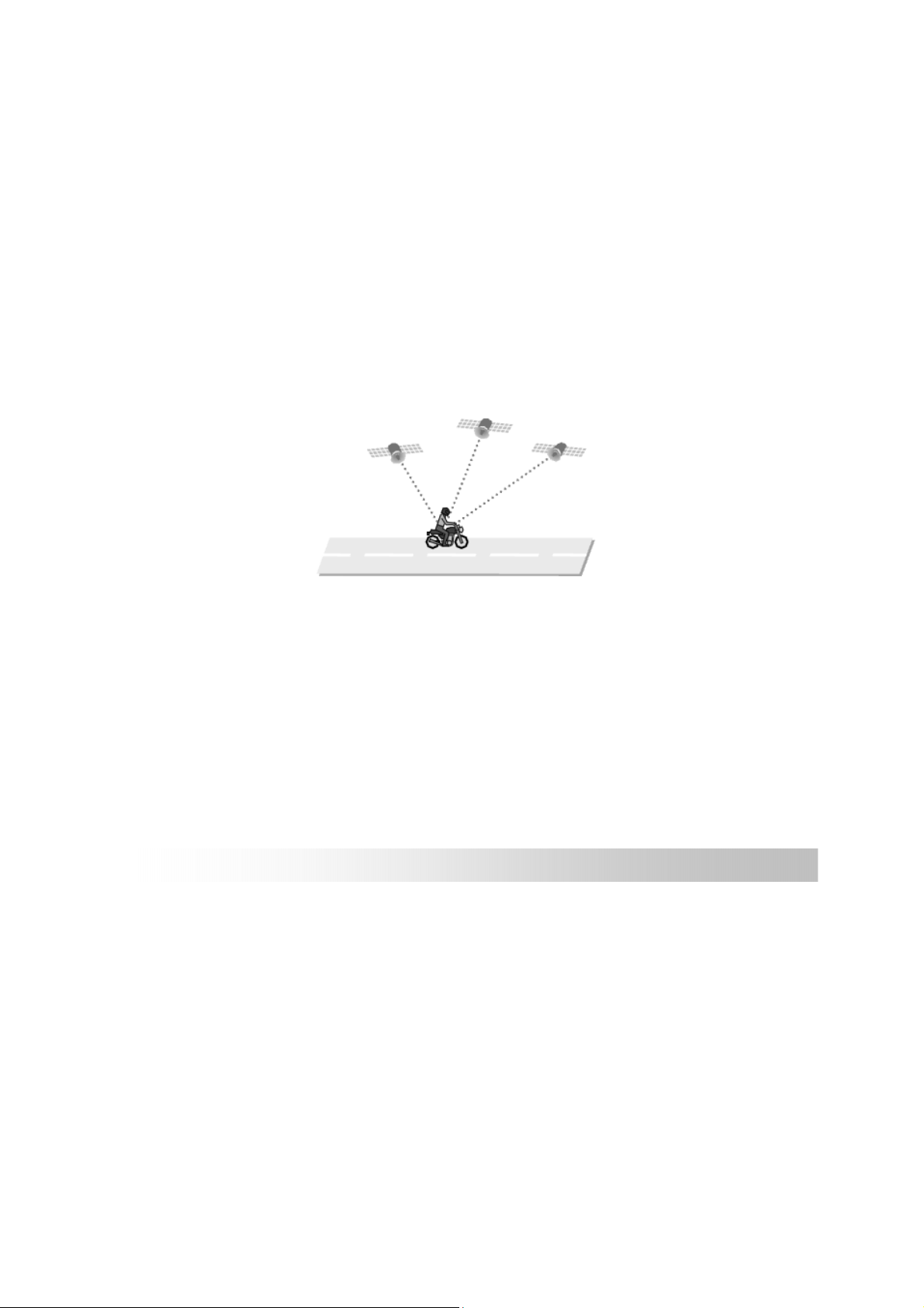
A minimum of 4 GPS satellite signals is needed to determine current
GPS position. Signal reception can be affected by situations such as
bad weather or dense overhead obstacles (e.g. trees and tall
buildings).
Other wireless devices in the vehicle might interfere with the
reception of satellite signals and cause the reception to be unstable.
1
Copyright
Without the written consent of HOLUX Technology, Inc, this manual,
including the product and the software, may not be duplicated, transmitted,
recorded or saved on storage devices. Furthermore, it shall not be
translated under any circumstances into any other languages.
Copyright ©2012 HOLUX Technology, Inc. All rights reserved.
Important Notice
Please thoroughly read this manual of operating instructions and
explanations. Only use original factory approved batteries and accessories
to prevent unexpected damage. If the correct procedures were not followed
for operation or incompatible accessories were connected, this is a
violation of the warrantee agreement and will automatically void the
warrantee. This may also cause personal safety issues.
2

Product Specification
Ite
m
Dimension
Weight
Processor
Memory
Audio
Display
Descripti
Typ. 130(L)x 92.2(W)x29(H) mm
Typ. 280 g (including battery)
on
SiRF Atlas IV 500MHz, ARM11.
FLASH: 4GB NAND Flash Memory(MLC)
RAM: 128MB DDR1(32bit)
32KB EEPROM
2S CODEC
Built-in Speaker (8 Ohm/2W)
480 RGB (W) x 272(H) dots, 4.3” Blanview LCD
0.198 mm dot pitch
RGB vertical stripe
LCM colors: 65536 colors(16 bits)
Brightness, Typ. 350 nits
Touch Panel
GPS
Man Machine
Interface
USB Interface
Activation force 100gf or less
3H hardness
SiRF 64 Channels, high sensitivity GPS Chipset
Internal Patch Antenna
8 directions Average C/No≧ 40dB, 3 highest satellites
Power on/off (Reset function)button x 1
Menu button x 1
Mini USB 2.0 connector
3

I/O Interface
Support 12pin I/O board for motorcycle cradle
Card Slot
Battery
Power
management
Power
Requirement
Bluetooth
module
Dustproof/Wate
rproof
Micro SD Slot x 1,
Micro SD™, Support 8GB(Max.), SD standard host
spec (2.0) compatible
Rechargeable Li-Ion battery 1050mAh
Normal voltage: 3.7V
Charger voltage: 4.2V
Suspend current typical 6mA
5.2V(+-)0.25V
NFORE, NF 2303
Bluetooth firmware version: H10620-V118R8(no
noise gate) Class 2: 0.25mW ~ 2.5mW
IP-57
4

B. Software Spec.
B.
Tools
1
Bluetooth
B.
Profile
2
support
Support upgrade OS&AP via Micro SD Card
Support Active Sync or Mass Storage via mini USB interface
HSP (Headset Profile)
Provide nFore Middleware for development
A2DP(Advanced Audio Distribution Profile)
Provide nFore Middleware for development
Class 2
C. Standard Accessories
C. 1 Car charger
C. 2
Motorbike
Charger
Cradle with
C.3
C.4
power
USB Cable
Input : 10.8V~30V; Output : 5V/2A
12V/5.3A
Quickly install design (with 12pin probe
connector)
IP-57
Transfer data from PC to GPSmile61CS
C.5
Cable quick
guide Tool
DVD Gift box
C.6
UART Cable
Don’t apply to Taiwan market.
Only apply to foreign user, such as European.
D. Optional Accessories
D. 1 Helmet speaker
D. 2 Control SW
ψ3.5phone jack 32 ohm 30mW( MAX_ 50mW)
Volume control button and up/down button
IP-57(Cable connector: water resistance)
5

E. Certification
CE/FCC FCC ID: RJI-NAV61CS
E. 1
PND Product Performance
Test Place: HOLUX
Long-term
F.19
Receive
Long-term Cold
F. 20
Start
Test Environment: Open sky at HOLUX building
Criteria: Average C/N≧40 dB, 3 highest sattelites
Position drift range≦15 m
Test Place: HOLUX
Test Environment: Open sky at HOLUX building
Criteria: TTFF ≦ 43s
PND Battery Life
Test Place: HOLUX Reliability Lab
Test Equipment: Use MV200 mobile corder,
Battery charge
F. 21
test
TopWard DC Power Supply 3303D and charging
test board
Criteria: Charging for 3.5 hours to full capacity
No functional failures allowed after charging.
Test Place: HOLUX Reliability Lab
Battery
F. 22
Discharge test
Test Equipment: Use MV200 mobile corder,
3302C electronic load mainframe and test board
Criteria:
Discharging for best loading time 4 hours to show
the low battery alert message
Discharging for full loading time 2 hours to show
the low battery alert message
No functional failures allowed after discharging.
6

First time use
Package Contents
Your product should include the following accessories:
GPSmile 61CS Cradle
DC-DC Adapter Car Charger
Screw kit (main accessory)
7

Motorbike RAM Mount Accessory
7
2
3
4
1
5
6
1. U-bolt Rail Mount 2. Device Base Plate
3. Motorcycle Handlebar Base 4. Double Socket Arm
5. Plastic Cushion 6. Square Rubber Neck
7. Screw kit (bolts, washers, spacers, nuts for motorbike RAM
mount)
8

y
Basic Operation
Introduction
Front View
Rear View
Main menu button
4.3’’ LCD
touch screen
Power button
Micro SD card slot
(Under battery cover)
Mini-USB connector
(Under battery cover)
Batter
9
cover

Accessories
Cradle
I/O cap
Screw
I/O interface
10

Getting Started
Install Cradle
1. Loosen the screw of
cradle top.
2. Open the cap of
cradle top.
3. Open the I/O cap.
screw
4. Insert the device
concave into the
cradle tabs.
Please make sure the
※
I/O pin is not wet or
dirty.
Concave
11

T
5. Slide the GPS into the
cradle fitting holes to
secure.
6. Make sure the device
is tightly fixed with
the bracket, and
gently close the
cradle cap.
7. Tighten the screw.
ab
12

Remove Cradle
1. Loosen the screw of
cradle top.
2. Open the cradle cap
and remove the
device.
3. Restore the I/O cap
13

C
Install motorcycle RAM mount
「A」Device Base Plate
「B」Double Socket Arm
「C」Motorcycle
Handlebar Base
A
Thread the bolts and nuts
(screw kit of main
accessory) to attach the
「A」to cradle.
Tighten the nuts to
secure the「A」.
B
A
14

There are two solutions to install Motorcycle RAM mount:
「motorcycle handlebar」or 「brake/ clutch」.
Method 1:
To install at handlebar
with U-bolt
(1) 「U-bolt」slip into
「Square rubber
Neck」to protect the
handlebar from
scratching.
15

(2) Place the U-bolt
around the handlebar,
and thread the ends
through the 「C」.
(3) To avoid slip, place
「plastic cushion」
between「U-bolt」and
handlebar.
(4) Tighten the nuts to
secure the base. Do
not over tighten.
Method 2:
To install at
clutch/brake clamp
bracket
C
(1) Remove the two
factory bolts on your
clutch/brake clamp
bracket.
(2) Thread the new bolts
(Screw kit of RAM
mount) through the
washers,「C」,
spacers, and clamp
bracket.
(3) Tighten the bolts to
secure the base.
※ There are long (QTY.2)
16

and short (QTY.2) bolts
in RAM mount screw kit,
please select that you
need to install.
After install the「C」at proper location, install other components.
Attach the ball of the
「C」with one side of
「B」.
Align the ball of the 「A」
with the other side of
「B」.
Tighten the knob slightly.
B
C
A
B
17

(1) Adjust「A」and「C」
for better viewing and
operation.
(2) Tighten the knob of
「B」to secure the
mount.
For your riding safety,
please loosen the knob of
「B」to adjust the screen
for better viewing and
operation.
After confirm the
viewing, tighten the knob
of「B」to secure the
mount.
A
B
C
Remind you: do not
operate the device when
you ride.
※ Note:
Damage due to modifications, improper installation, road
hazards or accident, are not covered. HOLUX does not liable
for any injury, loss, or damage, direct or consequential,
arising out of improper installation, or inability to use product.
18

Install/ Remove Battery
Please make sure the battery is installed before using the device.
1. Open the battery lid
2. Install or Remove the
battery
Printing side
facing up
Pull the
plastic to
remove the
battery
3. Restore the battery lid.
19

Device connection Diagram
GPSmile 61CS
DC-DC Adapter
(12V5V)
Car Charger
20

FCC Notices
This device complies with Part 15 of the FCC Rules. Operation is subject to the following
two conditions: (1) this device may not cause harmful interference, and (2) this device
must accept any interference received, including interference that may cause undesired
operation.
CAUTION: Change or modification not expressly approved by the party responsible
for compliance could void the user’s authority to operate this equipment.
This equipment has been tested and found to comply with the limits for a Class B
digital device, pursuant to Part 15 of the FCC Rules. These limits are designed to provide
reasonable protection against harmful interference in a residential installation. This
equipment generates, uses and can radiate radio frequency energy and, if not installed
and used in accordance with the instructions, may cause harmful interference to radio
communications. However, there is no guarantee that interference will not occur in a
particular installation. If this equipment does cause harmful interference to radio or
television reception, which can be determined by turning the equipment off and on, the
user is encouraged to try to correct the interference by one or more of the following
measures:
--Reorient or relocate the receiving antenna.
--Increase the separation between the equipment and receiver.
--Connect the equipment into an outlet on a circuit different from that to which the receiver
is connected.
--Consult the dealer or an experienced radio/TV technician for help.
CAUTION:
Any changes or modifications not expressly approved by the grantee of this device could
void the user's authority to operate the equipment.
RF exposure warning
This equipment must be installed and operated in accordance with provided instructions
and the antenna(s) used for this transmitter must be installed to provide a separation
distance of at least 20 cm from all persons and must not be co-located or operating in
conjunction with any other antenna or transmitter. End-users and installers must be
provide with antenna installation instructions and transmitter operating conditions for
satisfying RF exposure compliance."
 Loading...