


DFD-100 User Manual
DFD-100
Hypo-vigilance/
Fatigue Detector
User Manual
Ver. 1.9
Holux Technology Inc.

DFD-100 User Manual
Safety Precaution
• Due to different conditions and environments when
using DFD-100, users must take note of the
following information:
1. DFD-100 has passed rigorous test in detecting
driver hypo-vigilance (HPV)/ fatigue. However
wrong operation, external interference, or
malfunction, may affect the results; users must
bear the risk.
2. When installing the device, ensure correct
installation position. When using the device on
the road, take safety precautions and assume all
responsibilities. HOLUX will not bear any
responsibility.
3. DFD-100 is a standard HPV/ fatigue detection
device; it is not suitable for precise
measurements.
- ii -

DFD-100 User Manual
• Use the power adapter included with the package,
using power adapters other than the one provided
will result in malfunction and could prove
dangerous.
• About the power adapter:
1. Do not use the power adapter in a wet
environment. When hands and feet are wet, do
not touch the power adapter.
2. While using the power adaptor ensure that the
area is well ventilated. Do not let paper or other
material cover the power adaptor, as this will
interfere with cooling. Do not use the power
adaptor whilst it is in a bag.
3. Do not attempt to repair the device. If device is
damaged or is in a wet environment, replace
the device immediately.
4. It is not recommended to charge from a PC
because the PC power voltage is not enough to
- iii -

DFD-100 User Manual
supply the device.
• Suggestion! The user manual should be put in the car
to read any time.
- iv -

DFD-100 User Manual
Warranty Statement
• This warranty applies to parts and services that are
manufactured and sold through Holux Technology
Inc. The warranty length is one year from date of
purchase (starting from the date on the sales receipt).
Under normal user operation, Holux Technology
provides free repair services.
• Holux Technology is not responsible for providing
repairs or replacements of any software; Holux
Technology does not provide any warranty service
for third party software/hardware.
• Important instructions
1. This warranty does not cover damage or
malfunction from the below causes:
unauthorized disassembly/modification of unit,
abuse or incorrect usage, accidental and other
unpreventable causes, operation under variables
mentioned that are different from those in this
- v -

DFD-100 User Manual
product user manual, using parts not made or
sold by Holux Technology, or repairs done by
anyone other than Holux Technology and
authorized retail/service providers.
2. Expendable parts are not covered in the
warranty.
3. Please contact your local Holux Technology
authorized service provider to learn more about
geographical limitations, proof of purchase
requests, response time agreements, and other
specific maintenance service requests.
- vi -

DFD-100 User Manual
Copyright Information
No part of this manual, including the products and software
described in it, may be reproduced, transmitted,
transcribed, stored in a retrieval system, or translated into
any language in any form or by any mean, without the
express written permission of Holux Technology, Inc.
Copyright, All Rights Reserved.
Technical Support
• If there are any questions regarding the use of this
product, please log on to the website www.holux.com
and see the FAQ.
- vii -

DFD-100 User Manual
Table of Contents
Safety Precaution.....................................................ii
Warranty Statement................................................. v
Product Description ................................................2
Product Caution ..............................................4
Product Appearance ........................................5
Wearing and Activating the DFD-100......................8
Wearing the DFD-100 .....................................8
Disable alarm function ..................................13
Unbuckle the seat belt...................................14
DFD-100 Warning signals .....................................15
Warning Sound and LED display ...................15
Battery and Charging.............................................19
LED Power Display .......................................20
FAQ ......................................................................21
Technical Specifications........................................23
DFD-100.......................................................23
DFD-100 + Bluetooth...................................25
- 1 -

DFD-100 User Manual
Product Description
According to published studies and test results, the driver’s
vigilance level decreases (i.e. hypo-vigilance) due to long
hours driving on highways. The DFD-100 is a driver
hypo-vigilance(HPV)/ fatigue detector that detects driver’s
heart rate change to determine the driver’s HPV/ fatigue .
The DFD-100 issues a warning whenever the driver’s
vigilance level drops below the set-up limit.
The DFD-100 is based on the use of non-contact heart rate
sensing technology and a patented HPV/fatigue detection
algorithm. No electrode patches in direct contact with the
skin are required. The device is fitted to the driver's seat
belt and the device is ready to start operating when the
driver’s seat belt is fastened.
- 2 -

DFD-100 User Manual
Attention
The DFD-100 is an auxiliary driving safety device. When it
emits a warning beep, it means the driver’s vigilance level
is low due to fatigue . Driver fatigue is as dangerous as
drunk driving so when this happens, you should move to
the side of the road and stop driving for your own safety.
- 3 -
DFD-100 User Manual
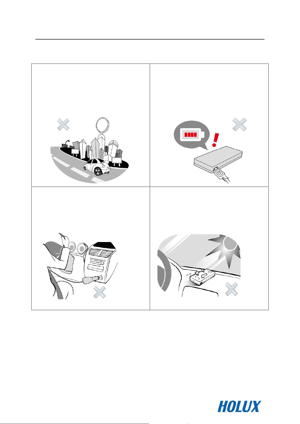
Product Caution
Do not use the device when
you drive on urban road.
Do not use the device when
charging.
Do not over charge.
Do not place the device
under the windshield to
solarization.
- 4 -

DFD-100 User Manual
Product Appearance
DFD-100 Unit
Product Appearance Legend
Item
①.
②.
Part Name
DFD-100
Unit
T-Bar This connects the Fixer and the
Function and Description
To use the DFD-100, first secure the
Fixer to the seat belt then attach the
device to the Fixer via the T-Bar on
the back.
DFD-100. Insert the T-Bar into the
T-Bar Mount and then push
downwards to clip it securely in
place.
③.
Buzzer Warning beeps are sounded from
here.
- 5 -

DFD-100 User Manual
the green LED will
④.
⑤.
Power LED
Power
Switch
Charging Status –
be turned on while charging. When
fully charged the green light will go
out.
※ Faces the right side of the driver
during use
Hold down for 3 seconds to switch
the DFD-100 on or off. Once the
device is switched on, it will beep
once and glow green for 10 seconds
to indicate that the device is now
running automatically.
⑥.
⑦.
Status LED
Mini USB
charging
socket
Once the device is switched on the
LED will glow green for 10 seconds
to indicate that the device is in
detection mode.
※ Faces the left side of the driver
during use
The mini-USB socket can be used to
connect to a power supply and
charge the device.
- 6 -

DFD-100 User Manual
Fixer
Item
⑧.
⑨.
Part Name
Function and Description
Fixer The Fixer is used for fitting the
DFD-100 to the seat belt.
T-Bar
Mount
This connects the Fixer and the
DFD-100. Insert the T-Bar into the TBar Mount and then push
downwards to click it into place.
- 7 -

DFD-100 User Manual
Wearing and Activating the DFD-100
Wearing the DFD-100
Step 1. Attach the DFD-100 Fixer to the seat belt.
The Fixer should be oriented with the wider end
pointing up. And the convex of Fixer is faced to users.
Step 2. Once the Fixer has been fitted to the seat belt, the
driver should then put on the seat belt.
- 8 -

DFD-100 User Manual
Step 3. Attach the DFD-100 unit to the Fixer.
Attention:
1. The T-Bar on the back of the DFD-100 should be
aimed at the wider end of the -shaped hole.
2. The driver should choose an appropriate -shaped
hole of the T-Bar Mount for their body shape. Press the
T-Bar into the wider end of the -shaped hole and
gently rotate around and push downwards to secure it.
Make sure that the trough on the T-Bar is clipped into
the narrower end of the
-shaped hole.
- 9 -

DFD-100 User Manual
Step 4. Confirm the positioning of the DFD-100.
Attention: The front of the DFD-100 must be positioned at
the center of the driver's chest with the buttons and light
indicators facing upwards. The lower edge of the DFD-100
should be level with a point 2 finger-width up from the
xiphoid process of the sternum (indicated spot ).
※ Because of body type differences, the detection
location may slightly differ. If the heart signal cannot be
detected from the proposed location, slightly adjust the
device location (adjust location as shown below). Please
wait 30 seconds~1minute for DFD-100 to detect the heart
signal. When you sound two short beeping means the heart
signal is successfully detected.
- 10 -

DFD-100 User Manual
3cm
3cm
2cm
2cm
Step 5. Adjust the location of the fixer.
Slide the fixer to adjust the position of the DFD-100.
- 11 -

DFD-100 User Manual
Step 6. Once the DFD-100 is properly in place turn on the
power switch.
When the DFD-100 is in the right place, hold down the
power switch for 3 seconds to turn on the power. Please
wait 30 seconds~1minute for DFD-100 to detect the
driver's heart signal. Two short beeping sounds indicate
that the heart signal is successfully detected.
- 12 -

DFD-100 User Manual
Attention
Driving on flat stretches of highway during long journeys
increases the risk of HPV/fatigue. This device is intended
primarily to be used when the driver is on a highway to
avoid accidents.
Disable alarm function
When DFD-100 emits audio alarms, you can choose to
silence it by pressing down the power switch once. If you
choose to silence it twice within one minute period, the
previous data will be erased and DFD-100 will reset the
detector function.
- 13 -

DFD-100 User Manual
Un
buckle
the seat belt
Step 1. Sliding downwards the Fixer and DFD-100.
Step 2. Unbuckle the seat belt; let the seat belt and
DFD-100 smoothly slide back.
- 14 -

DFD-100 User Manual
DFD-100 Warning signals
Warning Sound and LED display
The HPV/fatigue detected function is not enabled:
Warning
Power
Action
switch
Hold
Sound-
Beep
Status LED Power LED
Switch on
No
heartbeat
detected
=1 short Beep; —=1 long Beep
-=Green on 10 sec.; =Red flash 1
down 3
sec.
-
— -
(at 5 sec.
interval)
(at 5 sec.
interval)
-
-
- 15 -

DFD-100 User Manual
ed after
The HPV/fatigue detected function is enabled:
Warning
Action
Status LED
Sound- Beep
Heartbeat
detect
- -
device was
switched on.
Power LED
Heartbeat
detected
correctly
-
(at 2 sec.
interval)
Driver is
becoming
———
fatigue.
=2 short Beep; ———=3 long Beep;
=Green flash 1; =Red flash 3
-
-
- 16 -

DFD-100 User Manual
Action
Auto
power off
User
Power off
Low
Power
Bad
Signal
Power
switch
-
Hold
down 3
sec.
-
-
Warning
Sound- Beep
- ───
Status LED Power LED
- -
-
(at 30 sec.
interval)
─
───
-
quality
=4 short Beep; -=1 long Beep;
=3 short Beep; =1 short Beep
───= Red on; =Red flash 3;
─= Red on 5 sec
- 17 -

DFD-100 User Manual
Attention
※ If the driver's heartbeat signal is too faint for the
DFD-100 to detect, the DFD-100 will switch off 1 minute
after it loses the heartbeat signal.
※ Bad signal quality means the detected signal is
abnormal within 30 seconds continuously, such as: shake
body long time or wrong detected position.
- 18 -

DFD-100 User Manual
Battery and Charging
1. Charging with the Cigarette Lighter
The USB car charger can be used to connect the DFD-100
to the car's cigarette lighter for charging.
※ Do not use the device when charging.
- 19 -

DFD-100 User Manual
2. Charging with standard USB
Connect the mini-USB transformer directly to a standard
power socket to start charging.
LED Power Display
Power LED
Action Status Status LED
display
Plugged power
Plugged power
…=Green flash Continuously (1sec interval);
───=Green on
Charging - …
Fully
-
Charged
───
- 20 -

DFD-100 User Manual
FAQ
1. Why can’t I use DFD-100 when charging in the car?
The accessory of DFD-100 is included a car charger
for your convenience to charge in the car. Due to
driving safety, avoid distractions and the accuracy of
fatigue detection; do not use DFD-100 when charging
in the car.
2. Does DFD-100 have an instable detection in the
winter?
The DFD-100 detects driver’s heart rate change to
determine the driver’s fatigue level. The best distance
between the device and the skin is less than 5mm.
Suggestion: Do not wear heavy clothing when using
the device that in hence the accuracy of detection.
3. Does the fixer need to be attached and took off when I
use the device every time?
At first time; please attach the DFD-100 fixer to the
seat belt. When finished, you don’t need to take off
- 21 -

DFD-100 User Manual
the fixer; it can slide back with seat belt.
- 22 -

DFD-100 User Manual
Environmental
Technical Specifications
DFD-100
Fatigue
Detection
Dimensions 8.6 x 5.6 x 2.0 cm
Power
(PCB version)
- Accuracy 90%
- False alarm rate Less then 1%
- 3.7 Volt, 770 mAh, rechargeable
lithium battery
- 8 hours of continuous usage
- Charging time: 4 hours
(Charge the battery for 8 hours before
using this device for the first time.)
Key 1 key for power/ reset switch
I/O interface
specifications
Complies with IEC61000 & JAP WEPE electromagnetic
Mini USB for charging
- Operating Temperature: -10°C to 60°C
- Storage Temperature: -20% to 70%
- Charging Temperature: 0°C to 45°C
- Humidity: 30 to 90%
- 23 -

DFD-100 User Manual
compatibility of general industrial products.
Certificate number:
EN 55011: 2009+A1: 2010
EN 61000-3-2: 2006+A2: 2009
EN 61000-3-3: 2008
EN 60601-1-2: 2007
IEC 61000-4-2 Ed. 2.0: 2008
IEC 61000-4-3 Ed. 3.2: 2010
IEC 61000-4-4 Ed. 2.1: 2011
IEC 61000-4-5 Ed. 2.0: 2005
IEC 61000-4-6 Ed. 3.0: 2008
IEC 61000-4-8 Ed. 2.0: 2009
IEC 61000-4-11 Ed. 2.0: 2004
FCC Part 18: 2010
- 24 -

DFD-100 User Manual
DFD-100 + Bluetooth
Fatigue
Detection
- Accuracy 90%
- False alarm rate Less then 1%
Dimensions 8.6 x 5.6 x 2.0 cm
- 3.7 Volt, 770 mAh, rechargeable
lithium battery
Power
(PCB version)
- 8 hours of continuous usage
- Charging time: 4 hours
(Charge the battery for 8 hours before
using this device for the first time.)
Key 1 key for power/ reset switch
I/O interface
Bluetooth
module
(DFD-100 BT
only)
Mini USB for charging
Profile: SPP
Power: 3.3Vdc 65mA
RF Class type: class II
Baud rate: 57600 bps
Parity check: None
Data bits: 8 bits
Stop bit: 1bit
(The Bluetooth function is for engineer
use only.)
- 25 -

DFD-100 User Manual
Environmental
- Operating Temperature: -10°C to 60°C
- Storage Temperature: -20% to 70%
specifications
Complies with IEC61000 & JAP WEPE electromagnetic
compatibility of general industrial products.
Certificate number:
EN 55011: 2009+A1: 2010
EN 61000-3-2: 2006+A2: 2009
EN 61000-3-3: 2008
EN 60601-1-2: 2007
IEC 61000-4-2 Ed. 2.0: 2008
- Charging Temperature: 0°C to 45°C
- Humidity: 30 to 90%
IEC 61000-4-3 Ed. 3.2: 2010
IEC 61000-4-4 Ed. 2.1: 2011
IEC 61000-4-5 Ed. 2.0: 2005
IEC 61000-4-6 Ed. 3.0: 2008
IEC 61000-4-8 Ed. 2.0: 2009
IEC 61000-4-11 Ed. 2.0: 2004
FCC Part 18: 2010
FCC Part 15.247: 2010
- 26 -

DFD-100 User Manual
Bluetooth- class2 BT2.0 Module
Sensitivity
at 0.1%BER
RF Transmit
Power
Initial
Carrier
Frequency
tolerance
20dB bandwidth for
modulated carrier
Drift (Five slots packet) - 15
Drift Rate - 13
Frequency
Min
(GHz)
2.402 - -80
2.441 - -80
2.480 - -80
2.402 - 0 - dBm
2.441 - 0 - dBm
2.480 - 0 -
2.402 - 5 75 kHz
2.441 - 5 75 kHz
2.480 - 5 75
- 900
Typ
Max
-86 dBm
-86 dBm
-86
1000
- 40 kHz
- 20 kHz
BT
Spec.
≦
-70
≦
75
≦
1000
Unit
dBm
0
dBm
kHz
kHz
△f1avg
“Maximum
Modulation”
△f2max
“Minimum
Modulation”
2.402GHz
2.441GHz
2.480GHz
2.402GHz
2.441GHz
2.480GHz
140
140
140
115
115
115
165
165
165
190
190
190
175
175
175
- kHz
- kHz
-
140<△
f1avg
115
kHz
kHz
kHz
kHz
- 27 -

Federal Communications Commission (FCC) Statement
This equipment has been tested and found to comply with the limits for a Class B digital device, pursuant
to Part 15 of the FCC Rules. These limits are designed to provide reasonable protection against harmful
interference in a residential installation. This equipment generates, uses and can radiate radio frequency
energy and, if not installed and used in accordance with the instructions, may cause harmful interference
to radio communications. However, there is no guarantee that interference will not occur in a
particular installation. If this equipment does cause harmful interference to radio or
television reception, which can be determined by turning the equipment off and on, the
user is encouraged to try to correct the interference by one of the following measures:
- Reorient or relocate the receiving antenna.
- Increase the separation between the equipment and receiver.
- Connect the equipment into an outlet on a circuit different from that
to which the receiver is connected.
- Consult the dealer or an experienced radio/TV technician for help.
FCC Caution: Any changes or modifications not expressly approved by the party
responsible for compliance could void the user's authority to operate this equipment.
This device complies with Part 15 of the FCC Rules. Operation is subject to the following
two conditions: (1) This device may not cause harmful interference, and (2) this device
must accept any interference received, including interference that may cause undesired operation.
This equipment complies with FCC RF radiation exposure limits set forth for an
uncontrolled environment. To maintain compliance with FCC RF exposure compliance
requirements, please avoid direct contact to the transmitting antenna during
transmitting.
" This equipment must be installed and operated in accordance with provided instructions and the
antenna(s) used for this transmitter must be installed to provide a separation distance of at least 20 cm
from all persons and must not be co-located or operating in conjunction with any other antenna or
transmitter. End-users and installers must be provide with antenna installation instructions and transmitter
operating conditions for satisfying RF exposure compliance. "
 Loading...