

Page 1
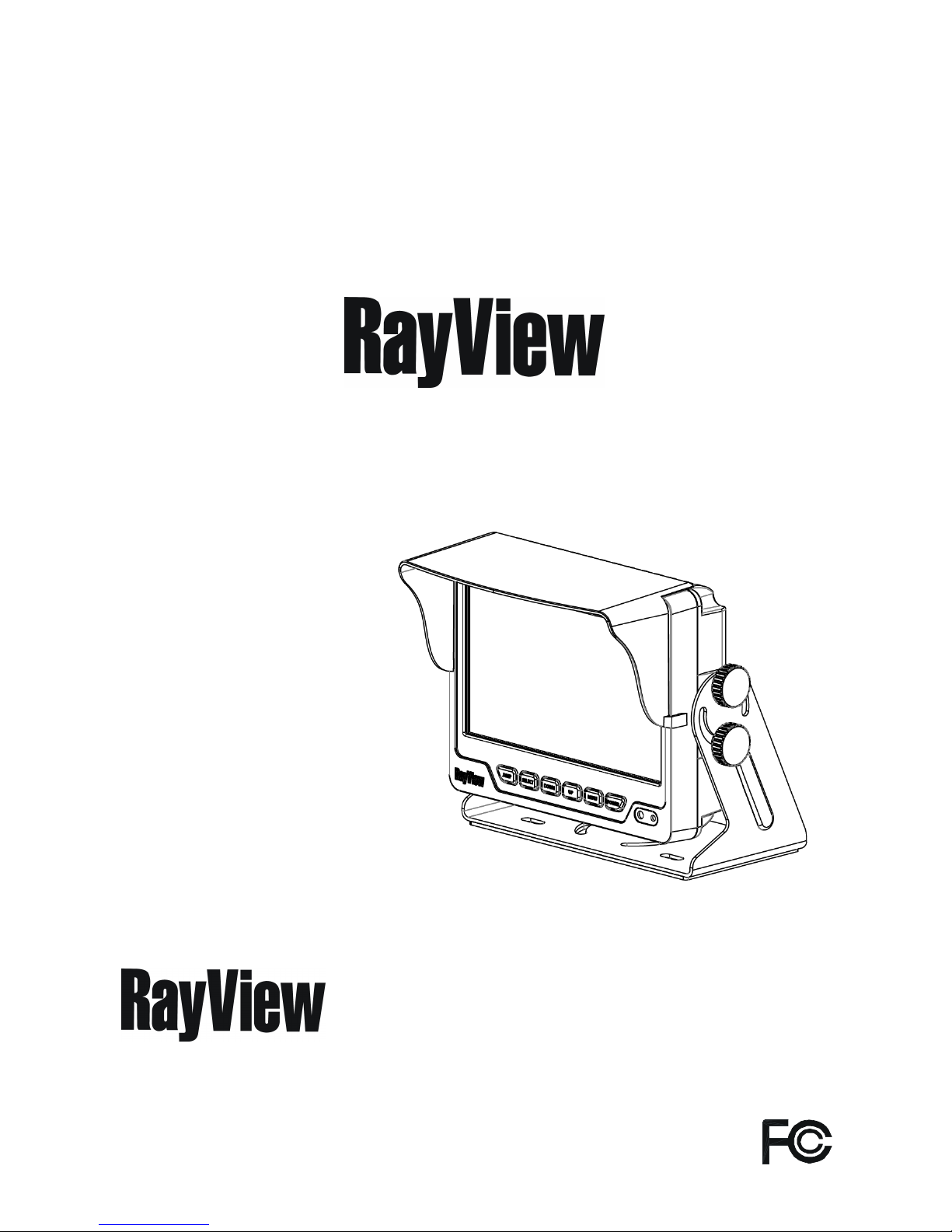
Thank you for purchasing our product.
Please read this User’s Manual before
using the product.
Change without Notice
7” Q TFT LCD MONITOR (LED Backlight)
USER MANUAL
Holtz Industries, INC.
200 South Terrace Court
Newark Ohio 43055
Tel: 1-800-535-0104
Page 2
2
Federal Communications Commission (FCC) Statement
This Equipment has been tested and found to comply with the limits for a Class
B digital device, pursuant to Part 15 of the FCC rules. These limits are designed
to provide reasonable protection against harmful interference in a residential
installation. This equipment generates, uses and can radiate radio frequency
energy and, if not installed and used in accordance with the instructions, may
cause harmful interference to radio communications. However, there is no
guarantee that interference will not occur in a particular installation. If this
equipment does cause harmful interference to radio or television reception,
which can be determined by turning the equipment off and on, the user is
encouraged to try to correct the interference by one or more of the following
measures:
- Reorient or relocate the receiving antenna.
- Increase the separation between the equipment and receiver.
- Connect the equipment into an outlet on a circuit different from that to
which the receiver is connected.
- Consult the dealer or an experienced radio / TV technician for help.
You are cautioned that changes or modifications not expressly approved by
the party responsible for compliance could void your authority to operate the
equipment.
Safety Precautions
This device complies with Part 15 of the FCC Rules. Operation is subject
to the following two conditions:
(1) This device may not cause harmful interference and,
(2) This device must accept any interference received, including interference
that may cause undesired operation.
Page 3

3
Safety Precaution.……..……………………………………………………………… 2
Table of Content.….…………………………………………………………………… 3
Features...……………………………………………………………………………… 4
Package Contents…….………………………………………………………….…… 4
TFT Installation………………………………………………………………………… 5
Signal Cable Description……..………………………………………………….…… 6
Control Cable Description……..……………………………………………………… 8
Front Panel Control.…………………………………………………………………… 9
OSD Menu ………………………..…..………………………………………….. 10
Video Setting Menu……………………………………………………….………. 11
Display Setting Menu……………………………………………………………… 12
Camera Setting Menu……………………………………………………………. 13
Information…………………………………………………………………………. 16
Vehicle Installation ………………………….………………………………………… 17
Specification…..………………………………………………………………….…… 18
Attachment…..…………………………………………………………………….…… 19
Table of Content
Page 4
4
Advanced OSD Menu for easy use
Support up to 4 CCD Camera Inputs (Mini din Connector)
Extra RCA Input for Multimedia (VCD, DVD, Game Device)
Provide 1 Live Video / Audio Signal Output / Cam Out
Auto Detection for NTSC / PAL System
Signal Trigger for CAM A / CAM B / CAM C /CAM R / AV View
Auto Brightness Adjustment by light sensor
OSD Control for Individual Normal / Mirror Camera Image
Switch Timer (2-100 sec) Step Selection via OSD (CAM A / CAM B / CAM C /CAM
R / AV)
Supported 9.6V~32V Car power system working
Item Qty.
1. 7” LCD Monitor 1
2. Sun-hood 1
3. Mounting Bracket 1
4. Accessories 2
5. Control Cable 1
6. User Manual 1
Features
Package Contents
Page 5
5
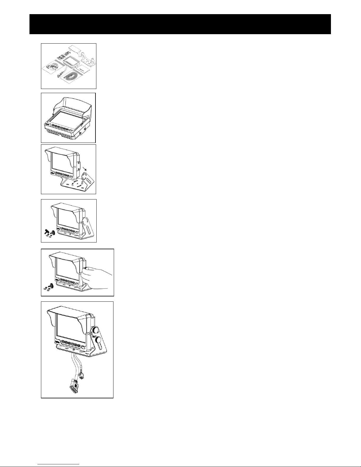
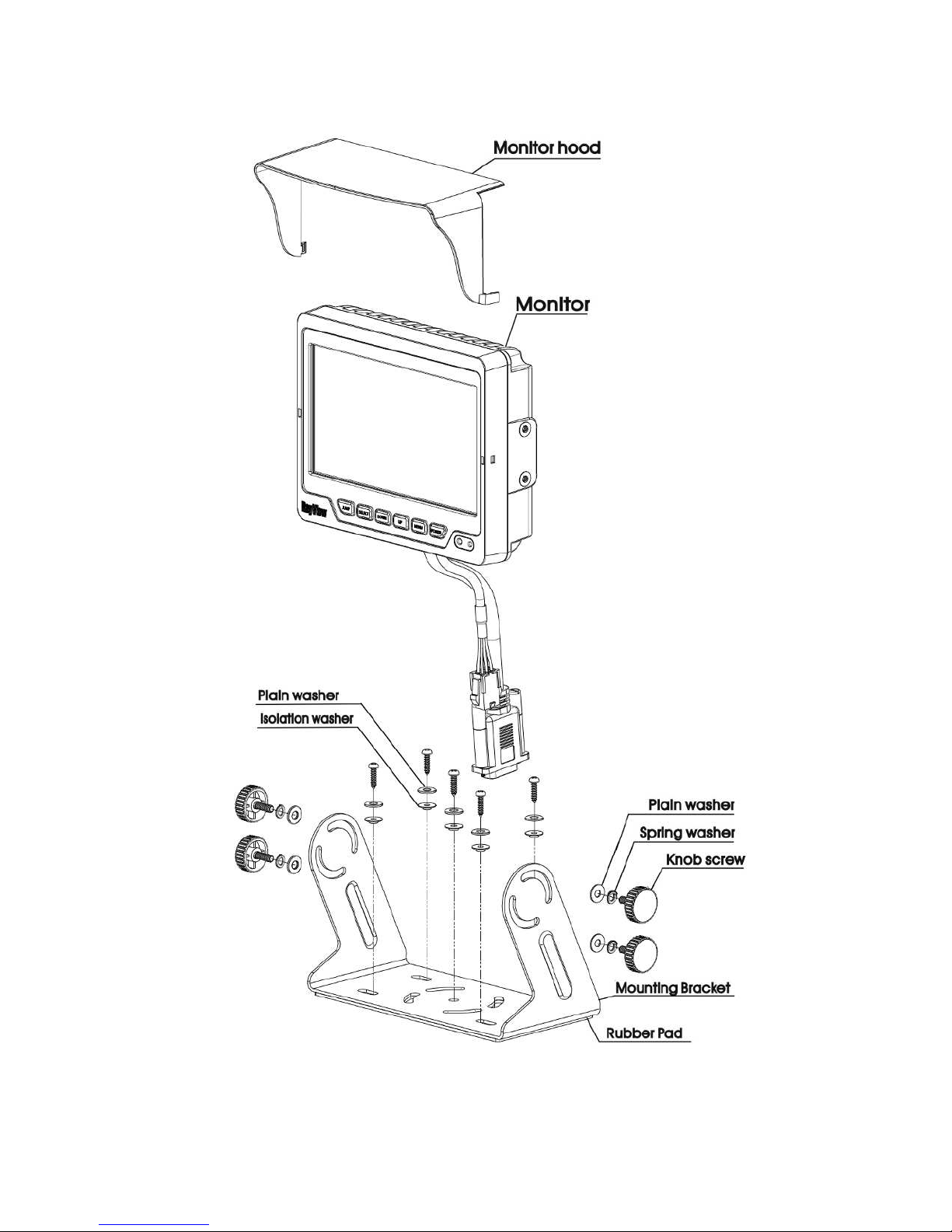
Step 1
Check the package and make sure all parts are
included
Step 2
Clip the sun-hood on to the monitor
Step 3
Make sure it is installed properly
Step 4
Install the monitor on to the bracket
Step 5
Adjust the monitor to an appropriate / comfortable
viewing angle before tightening the screws
Step 6
Monitor installation is now completed.
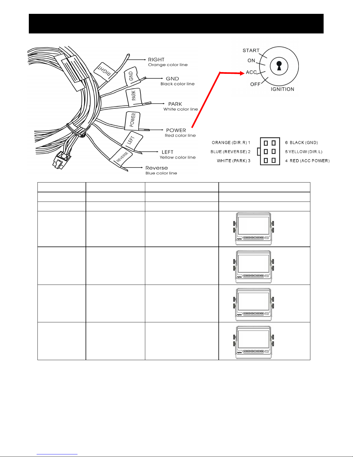
Each control cable wire is attached with a sticker to
indicate its signal function. Referred to the
identification sticker for further installation.
TFT Installation
Page 6
6
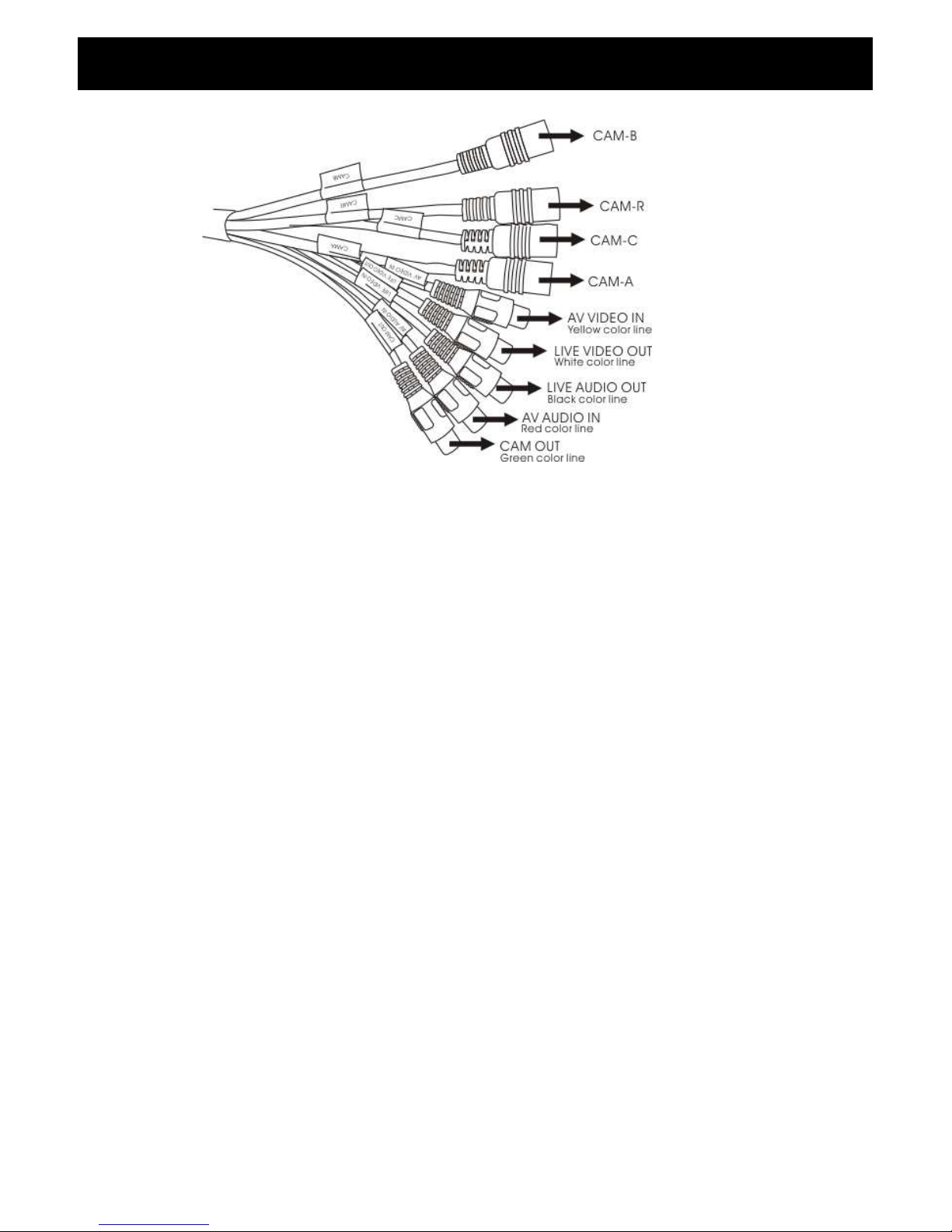
1. CAM A (Mini din)
For 1st camera connection
2. CAM B (Mini din)
For 2nd camera connection
3. CAM C (Mini din)
For 3rd camera connection
4. CAM R (Mini din)
For 4th camera connection
5. LIVE VIDEO OUT (White Color RCA Jack)
On screen video loop out (for recording, second monitor or other device)
6. LIVE AUDIO OUT (Black Color RCA Jack)
On screen audio loop out (for recording, second monitor or other device)
7. AV VIDEO IN (Yellow Color RCA Jack)
Connection for any Video signal (DVD, VCD, Game)
8. AV AUDIO IN (Red Color RCA Jack)
Connection for any Audio signal (such as DVD, VCD, Game)
9. CAM OUT (Green Color RCA Jack)
Video loop out (for recording, second monitor or other device)
Signal Cable Description
Page 7
7
4
6
5
3
2
1
※ Cam Out: Composite video loop out signal to recorder, monitor or other device.
※ Live Video/Audio Out: On screen video/audio signal loop out to recorder, monitor
or other device.
Cam A Audio from Cam A
Cam B Audio from Cam B
Cam C Audio from Cam C
Cam R Audio from Cam R
Cam A + Cam B Audio from Cam A
Cam C+ Cam R Audio from Cam R
Cam A+ Cam R Audio from Cam R
Cam R+ Cam B Audio from Cam R
Cam A + Cam C Audio from Cam A
Cam C+ Cam B Audio from Cam C
Cam R / Cam AB Audio from Cam R
Quad Audio from Cam R
AV Audio from AV
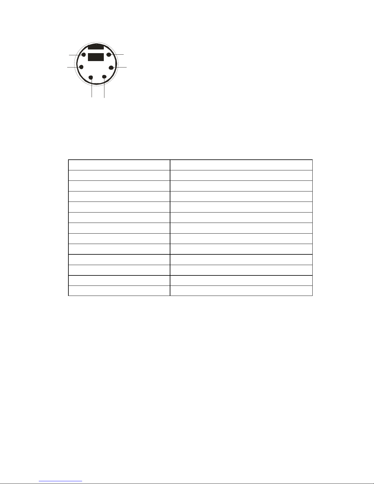
Mini Din Pin Assignment
Function of the Audio
* Type 1 (Standard):
1. ----- 4. GND
2. ----- 5. +12V
3. Audio 6. Video
*Type 2 (Optional):
1. GND 4. +12V
2. ------ 5. -------
3. Video 6. Audio
Page 8
8
WIRE COLOR FUNCTION REMARK ON SCREEN VIEW
RED ACC POWER
BLACK GND
WHITE Parking Control Active GND
YELLOW Left turn Control
(Correspond to
CAM A)
Active Power Level
Connect to Direction
Light(Left Turn Light)
ORANGE Right turn
(Correspond to
CAM B)
Active Power Level
Connect to Direction
Light(Right Turn Light)
BLUE Reverse Control
(Correspond to
CAM R)
Active Power Level
Connect to Reverse
1. The control cable sequence: Reverse > Right / Left > Park (AV)
2. With car power is on, the monitor power is off, when making a reverse / right / left turn, the
monitor will display default screen.
3. *When pull the hand break, user need to press SOURCE button again to display AV IN picture.
Control cable
Description
Don’
t connect the red wire (power wire) of this
prod
uct directly to the battery. Connect the red
wire of this
product
to the ACC of the ignition key
switch. Failure to do so may result in permanent
damage of the product.
A V
CAM R
CAM
B
CAM
A
Page 9
9
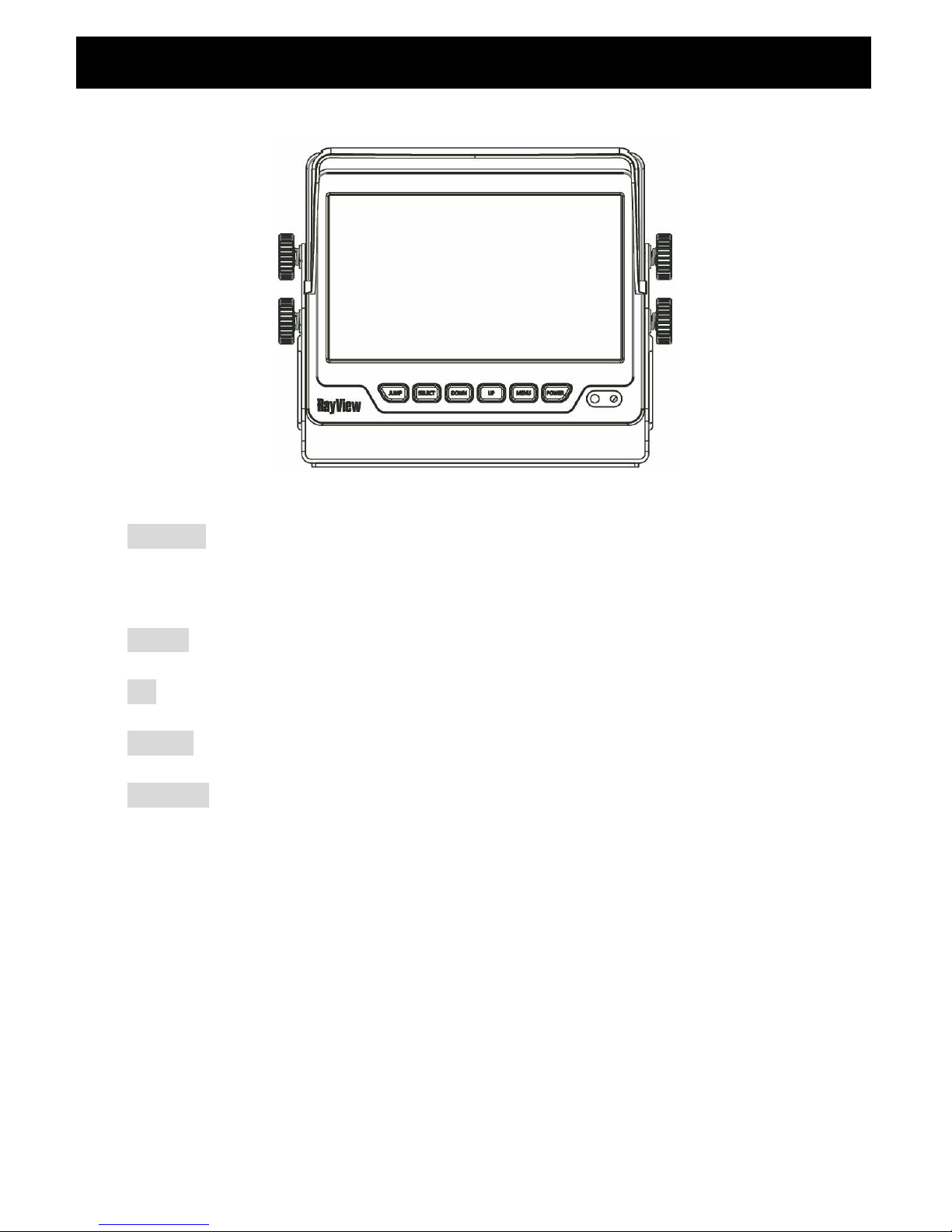
POWER Press the power button to activate the monitor or to keep the monitor
under stand by mode. Red light for stand by, Green light is turn on.
MENU Press the menu button to pop up OSD menu.
UP Scroll up the function item or increase value.
DOWN Scroll down the function item or decrease value.
SELECT With power on press this button to select image sequence.
CAM ACAM BCAM CCAM R CAM A+B CAM C+R
CAM A+RCAM R+BCAM A+CCAM C+B CAM R/AB
CAM R+ABCAM A……
With pull hand break, press this button to select image sequence
AVCAM A+BCAM C+RCAM A+RCAM R+BCAM A+C
CAM C+BCAM R/ABCAM R+ABCAM ACAM BCAM C
CAM R AV……..
Front Panel Control
Page 10
10
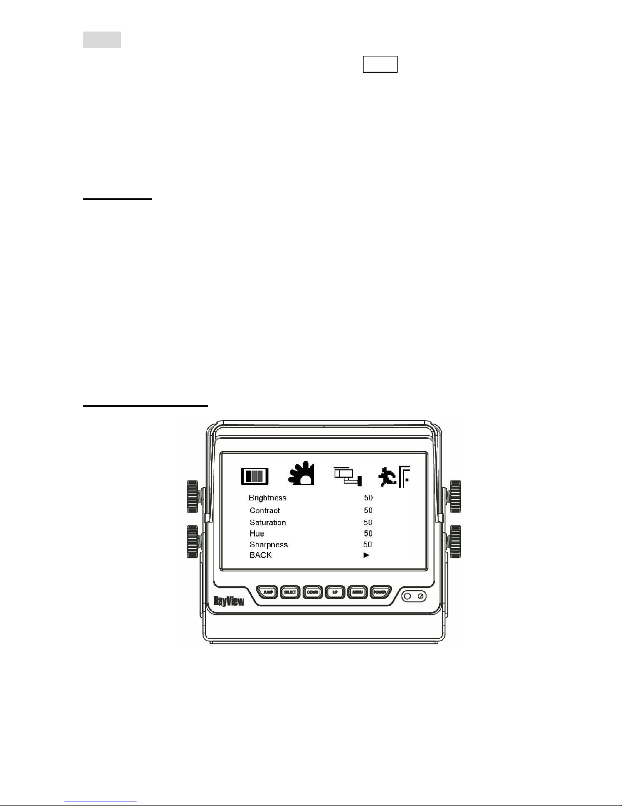
JUMP Press this button, it can switch CAM A, CAM B, CAM R recurrently.
With pull hand break and check the Jump option is ON, press
this button to select image sequence
QUADSEQCAM A+BCAM C+RCAM A+RCAM R+B
CAM A+CCAM C+BCAM R/AB CAM R+AB CAM A
CAM B CAM CCAM R, The default value is QUAD.
OSD Menu
1. Press the MENU button to enter to the OSD Menu
2. Press UP & Down button to select the setting you wish to proceed.
The picture of the content will turn rise high to identify your selection.
Press UP & Down button to adjust your setting value.
3. Press the MENU button once back to submenu and then select the
BACK item in order to return to OSD menu.
Enter to Main Menu
Page 11
11
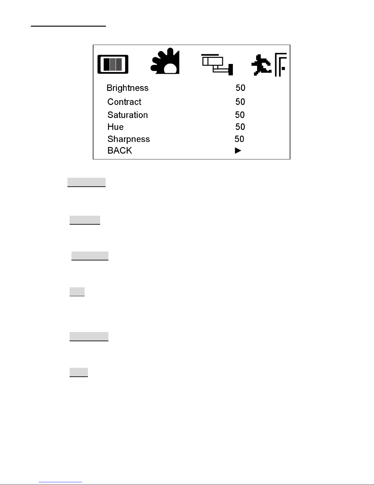
Video Setting Menu
This menu set up contains different setting for the TFT LCD.
Brightness
Provide adjustment for shade and brightness level of TFT display.
Setting value from 0 ~ 100. Default value is 50.
Contrast
Provide adjustment for the light and dark level of the TFT display.
Setting value from 0 ~ 100. Default value is 50.
Saturation
Provide adjustment for the light intensity level of TFT display.
Setting value from 0 ~ 100. Default value is 50.
Hue
Provide adjustment for the lightness and colorfulness level of TFT display.
Setting value from 0 ~ 100. Default value is 50.
(Only in NTSC system is available.)
Sharpness
Provide adjustment for the edge contrast (acutance) level of TFT display.
Setting value from 0 ~ 100. Default value is 50.
Back
Return to OSD menu selection screen.
Page 12
12
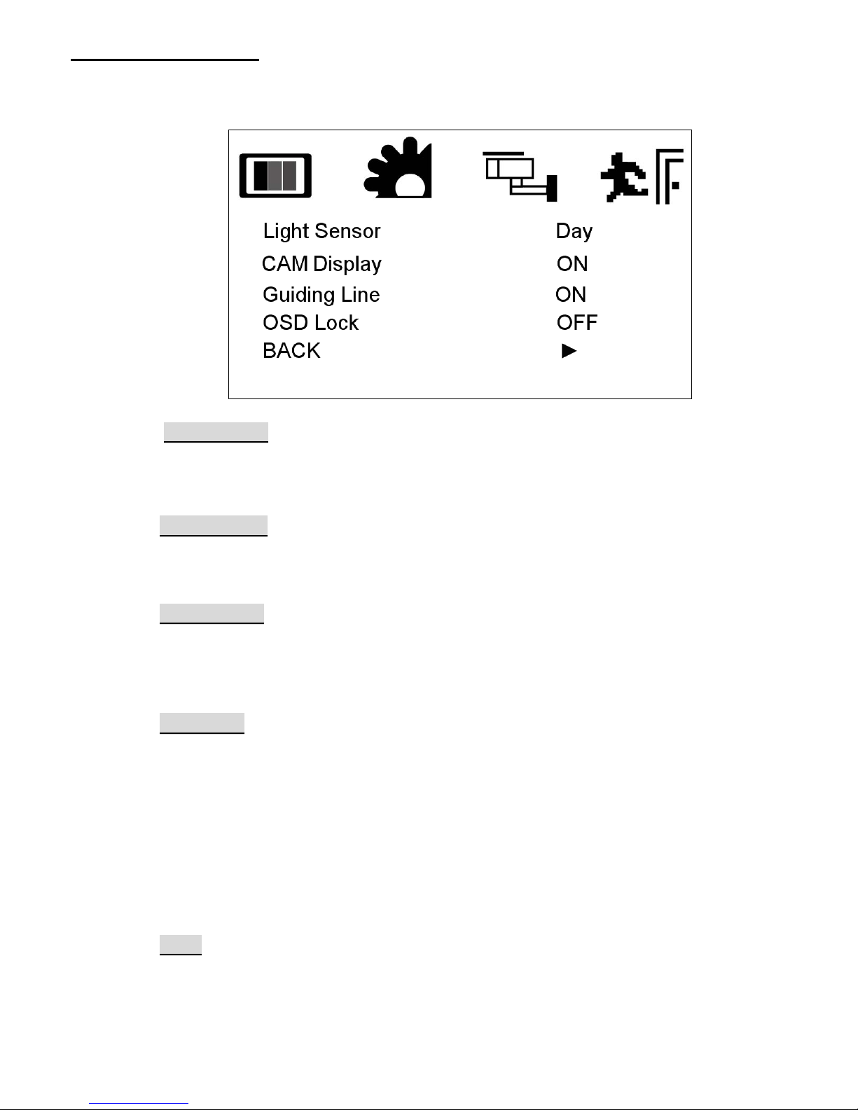
Display Setting Menu
This menu set up contains the on screen identification and the activation
of the distance gage.
Light Sensor
Select “Auto” to activate the auto brightness adjustment function for screen.
Or select “Night” to reduce the brightness for screen.Default value is Day.
CAM Display
Select “ON” to show the source of video input title on screen or “OFF” to
keep it invisible. Default value is ON.
Guiding Line
Set the distance gauge “ON” to show the distance gauge on screen while
reserving or “OFF” to deactivate. Default value is ON.
(This “Guiding Line” is for user’s reference only)
OSD Lock
This function provides protection when an unauthorized person tries to
access the OSD settings. UP and DOWN key press simultaneously for over
5 seconds to unlock. Default value is OFF.
※Users must turn on LCD in order to run unlock process. All function
buttons are still working during OSD Menu lock up period.
Back
Return to OSD menu selection screen.
Page 13
13
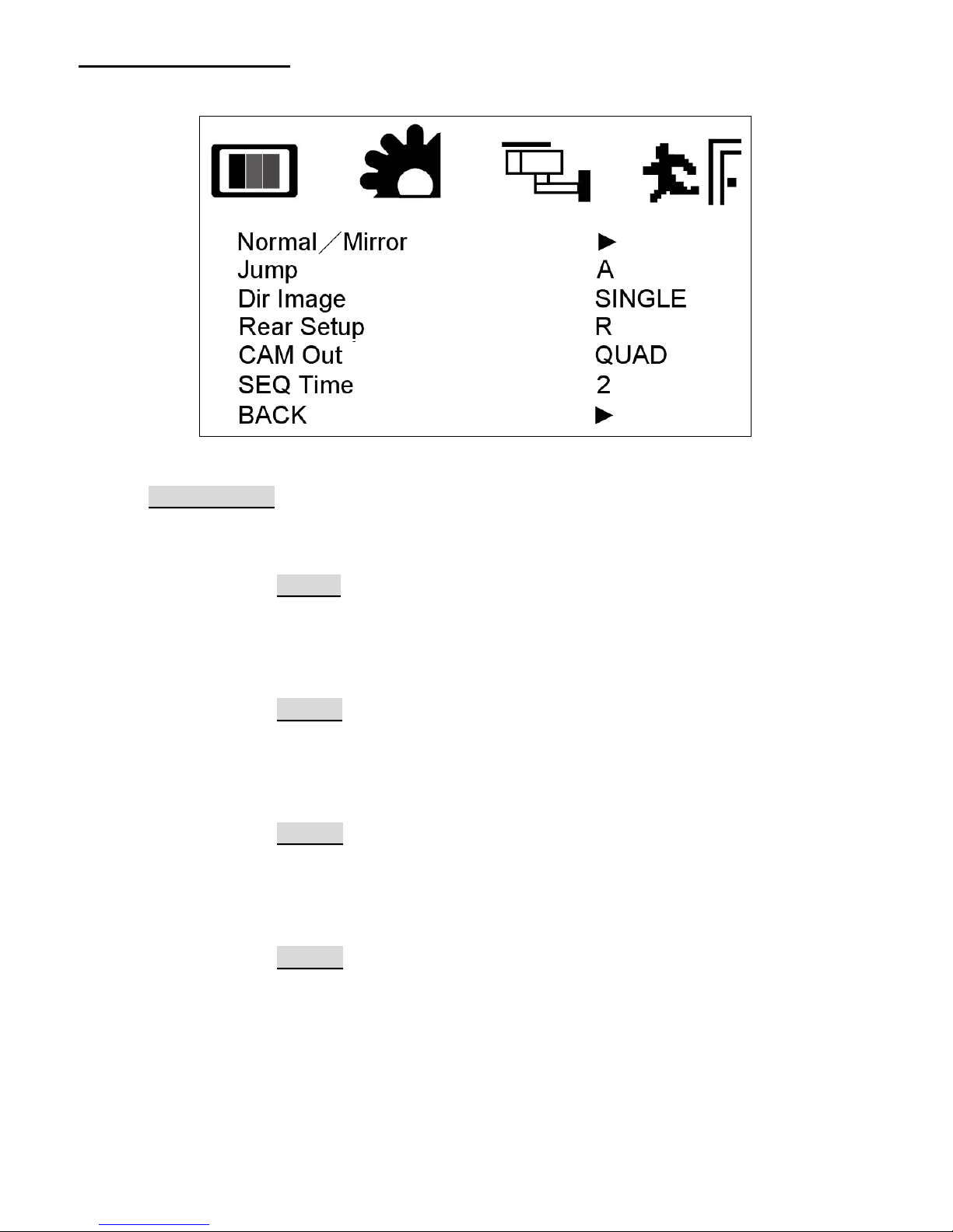
Camera Setting Menu
This menu set up contains the on Camera and Jump setting.
Normal/Mirror
Set the all camera’s display mode. ►
CAM A
Select “Mirror” to activate the mirror function for different cameras
or “Normal” for a normal image.
Default value is Normal.
CAM B
Select “Mirror” to activate the mirror function for different cameras
or “Normal” for a normal image.
Default value is Normal.
CAM C
Select “Mirror” to activate the mirror function for different cameras
or “Normal” for a normal image.
Default value is Normal.
CAM R
Select “Mirror” to activate the mirror function for different cameras
or “Normal” for a normal image.
Default value is Mirror.
Page 14
14
Jump
Jump provide automatically channel switch function.
Setting value from SEQ, A+B, C+R, A+R, R+B, A+C, C+B, R/AB, R+AB
,A ,B , C, R, QUAD. Default value is QUAD.
Dir Image
The screen image setting of this panel during left / right turn:
TRIPLE: When you are making a right turn or left turn, the screen of
panel will display triple images for left hand side, right
hand side and rear view when you are making a right turn
or left turn.
DUAL: With proper wiring, the screen will display dual image for
both rear and right hand side view when making a right turn.
While left turning, the screen will show dual image for both
rear and left hand side view.
SINGLE: Screen of touch panel shows only single picture on direction
turn. The screen will show only left side view on left turn and
only right side view on right turn.
A+B, B+A : With proper wiring, When you are making a left turn the
screen will display Cam A + Cam B image. When make a right
turning, the screen will show Cam B + Cam A image on the
screen.
Default value is SINGLE.
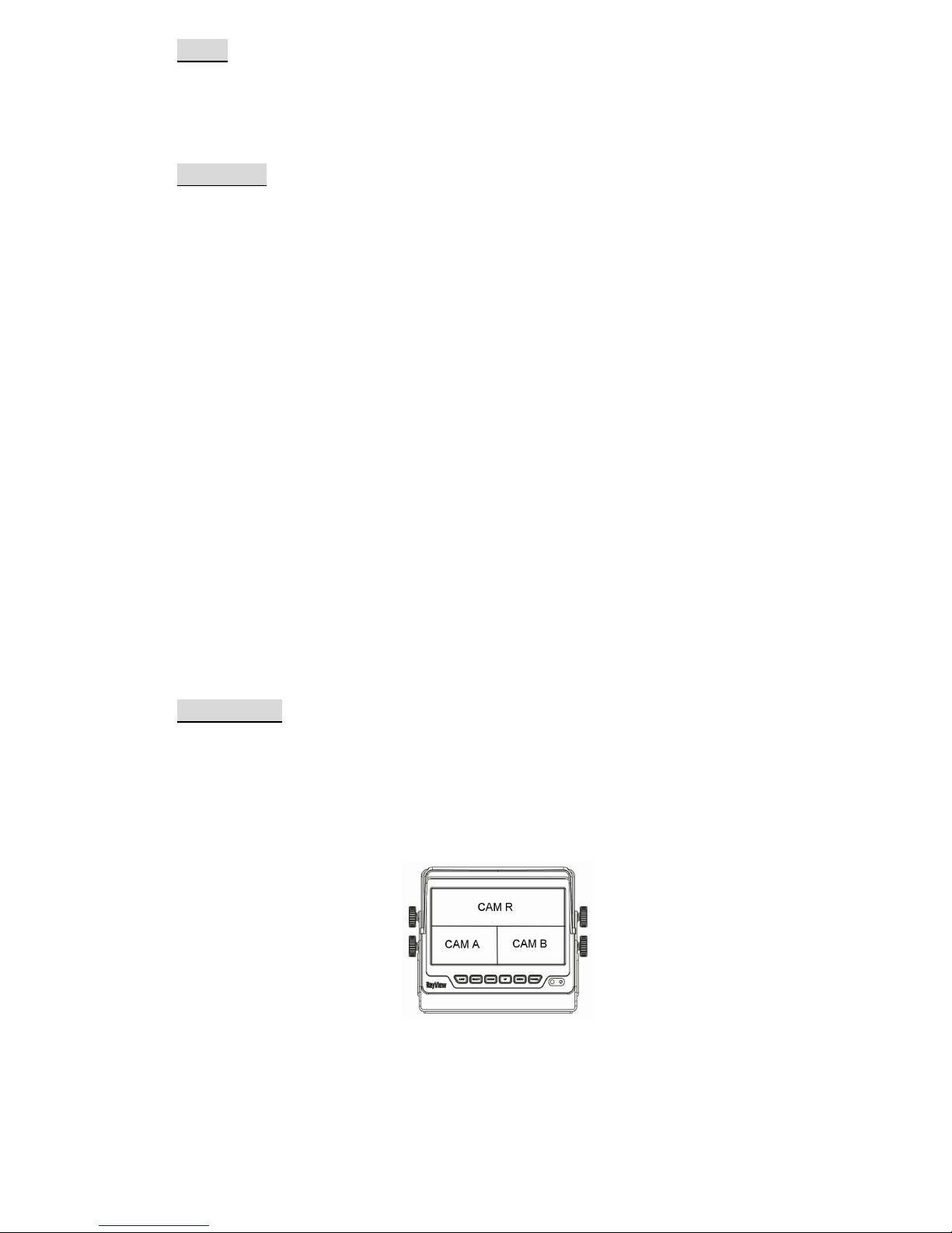
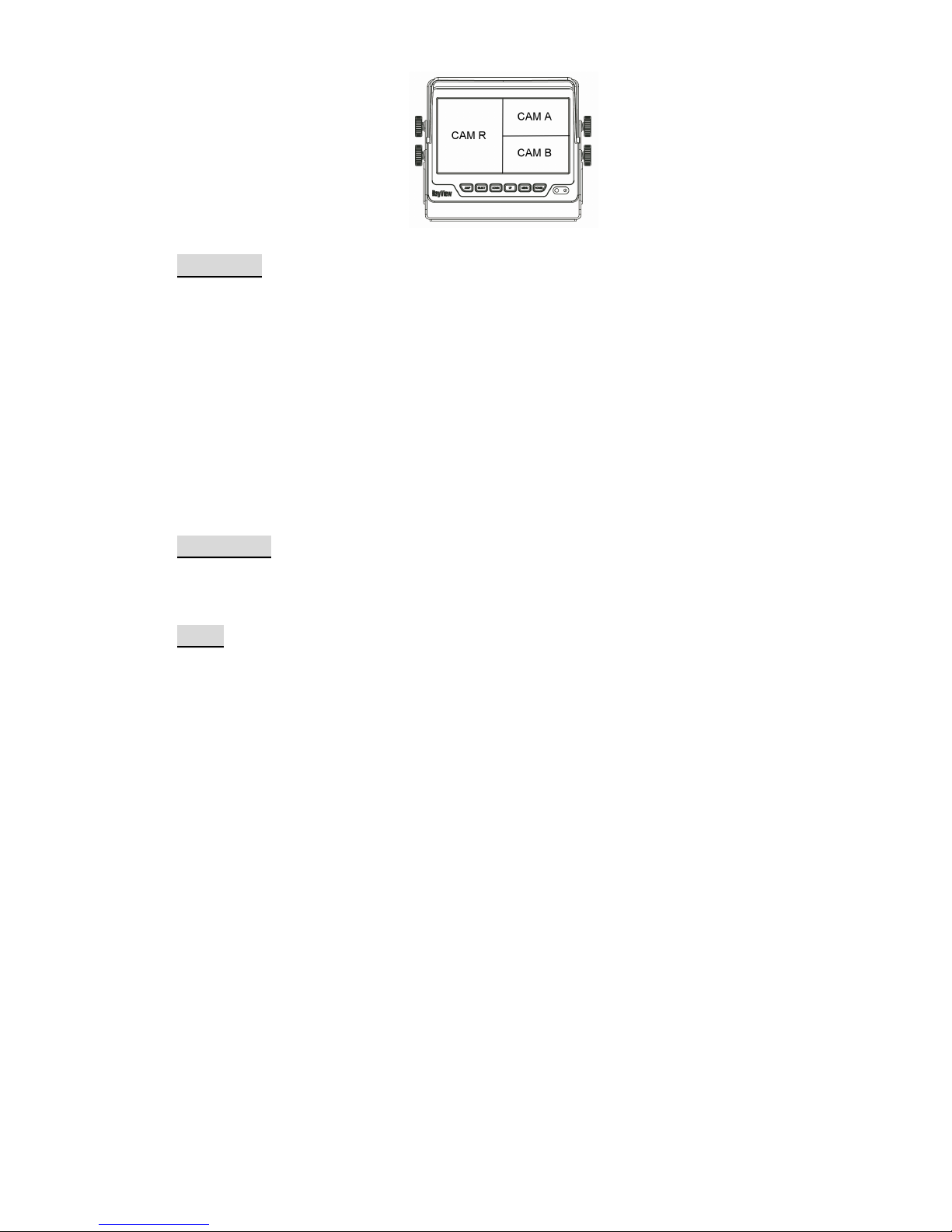
Rear Setup
The screen image setting of this panel during reverse gear:
R: Screen will display single image for Cam R only.
R+A: Screen will display dual image for both Cam R and Cam A.
R+B: Screen will display dual image for both Cam R and Cam B.
R/AB: Screen will display triple image from Cam R、Cam A、Cam B.
Page 15
15
R+AB: Screen will display triple image from Cam R、Cam A、Cam B.
Default value is R.
CAM Out
Composite video loop out to recorder, monitor or other device.
QUAD Recording or viewing from the output device in quad mode
CAM A Recording or viewing from the output device for CAM
A image
CAM B Recording or viewing from the output device for CAM
B image
CAM C Recording or viewing from the output device for CAM
C image
CAM R Recording or viewing from the output device for CAM
R image
Default value is QUAD.
SEQ Time
Setting Jump dwell value from 2~100.
Default value is “2”.
Back
Return to OSD menu selection screen.
Page 16
16
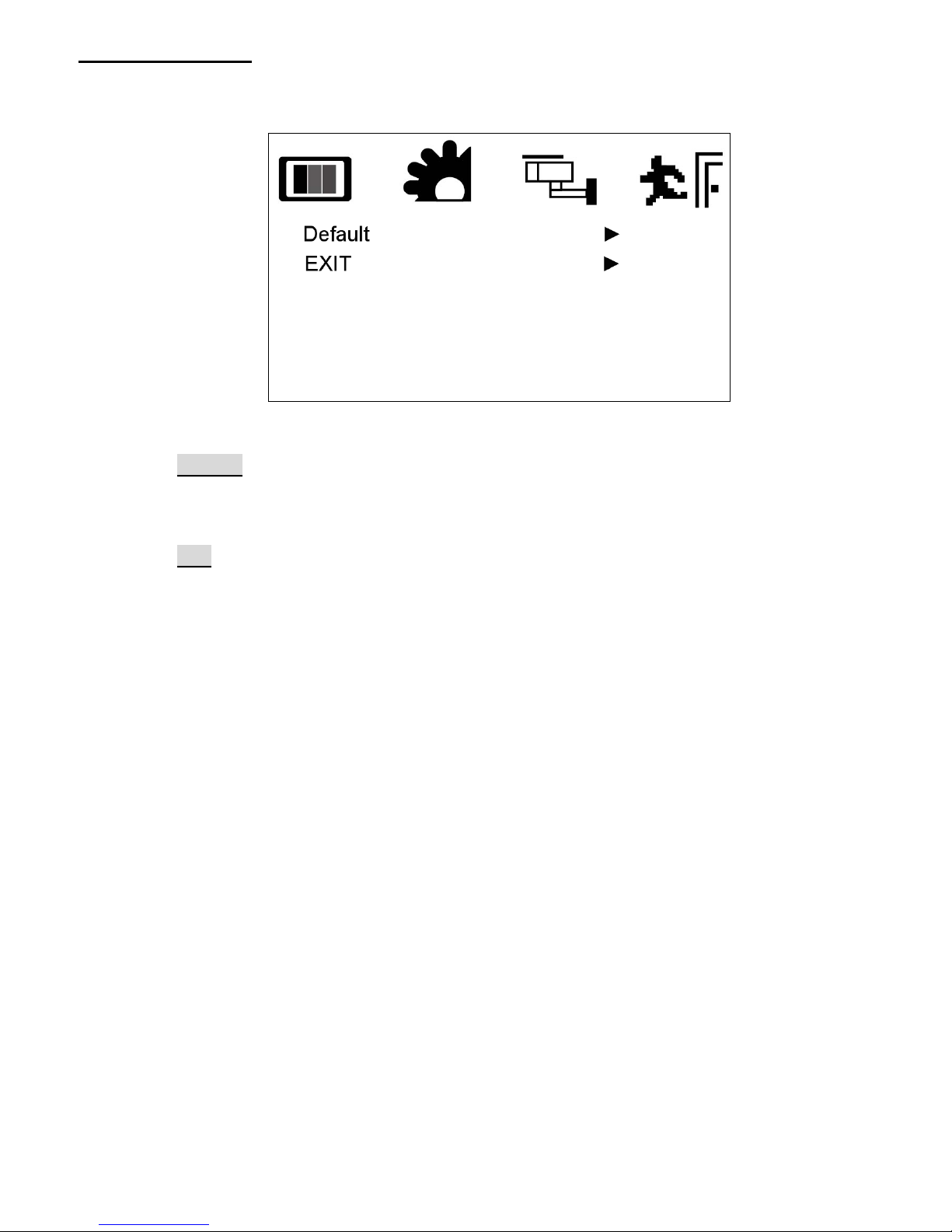
Information Menu
This menu can set device to default value and leave the OSD menu.
Default
Recall factory default.
Exit
Exit OSD menu to live screen.
Page 17
17
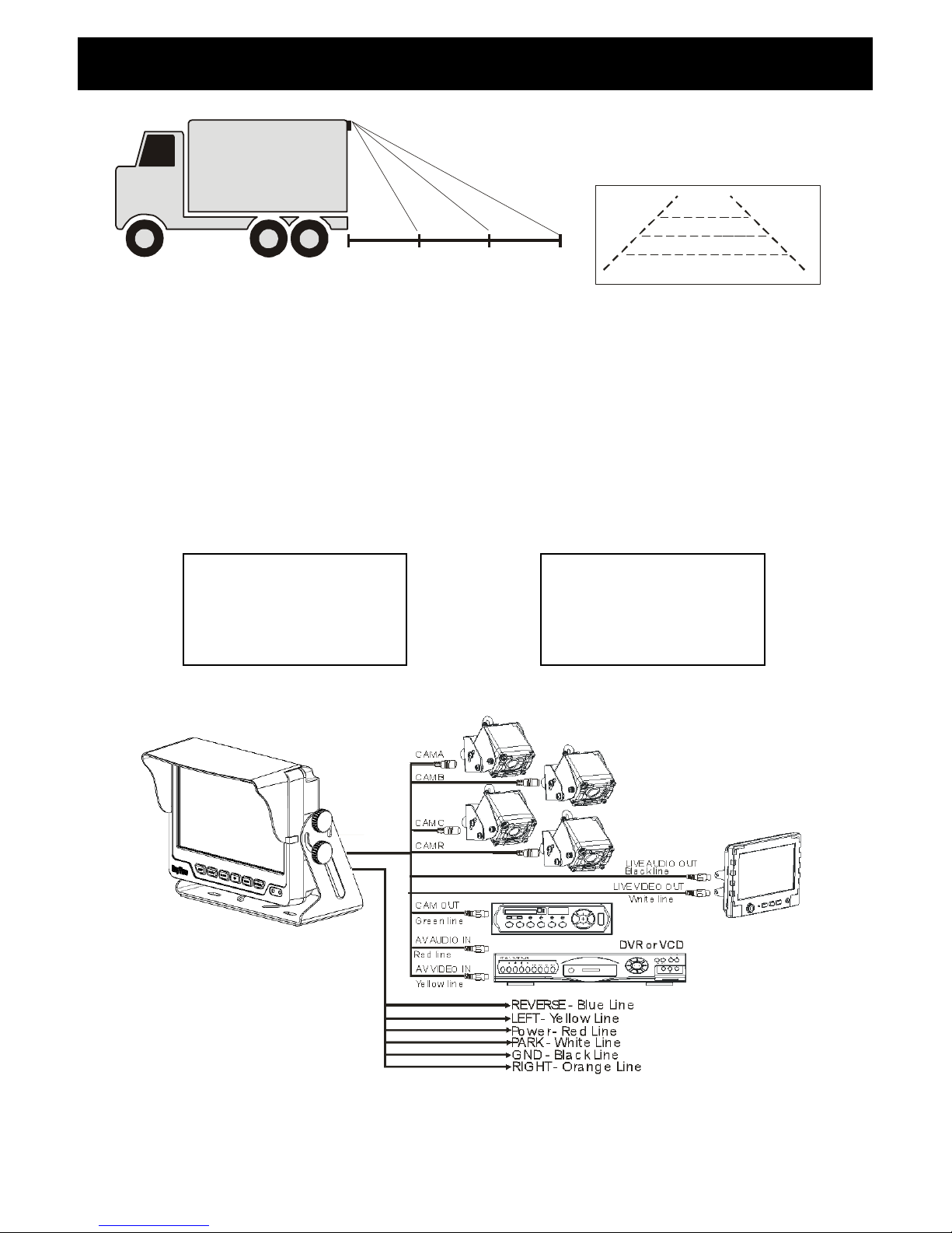
a. Install Camera R (for rear view)
b. Use a measuring tool to mark out the distance behind the vehicle.
c. Adjust the viewing angle of the camera so that the distance gage shown from
the TFT match to the distance marks behind the vehicle.
d. Switch to Rear view with source button, the screen always display on 16:9
While rear viewing, the screen always display on 16:9.
SOURCE button: Rear viewing:
16
e.
0M 1M 2M 3M
Red Yellow Green
Camera
Green
Red
Yellow
1M
Vehicle Installation
9 9
9
16
Page 18
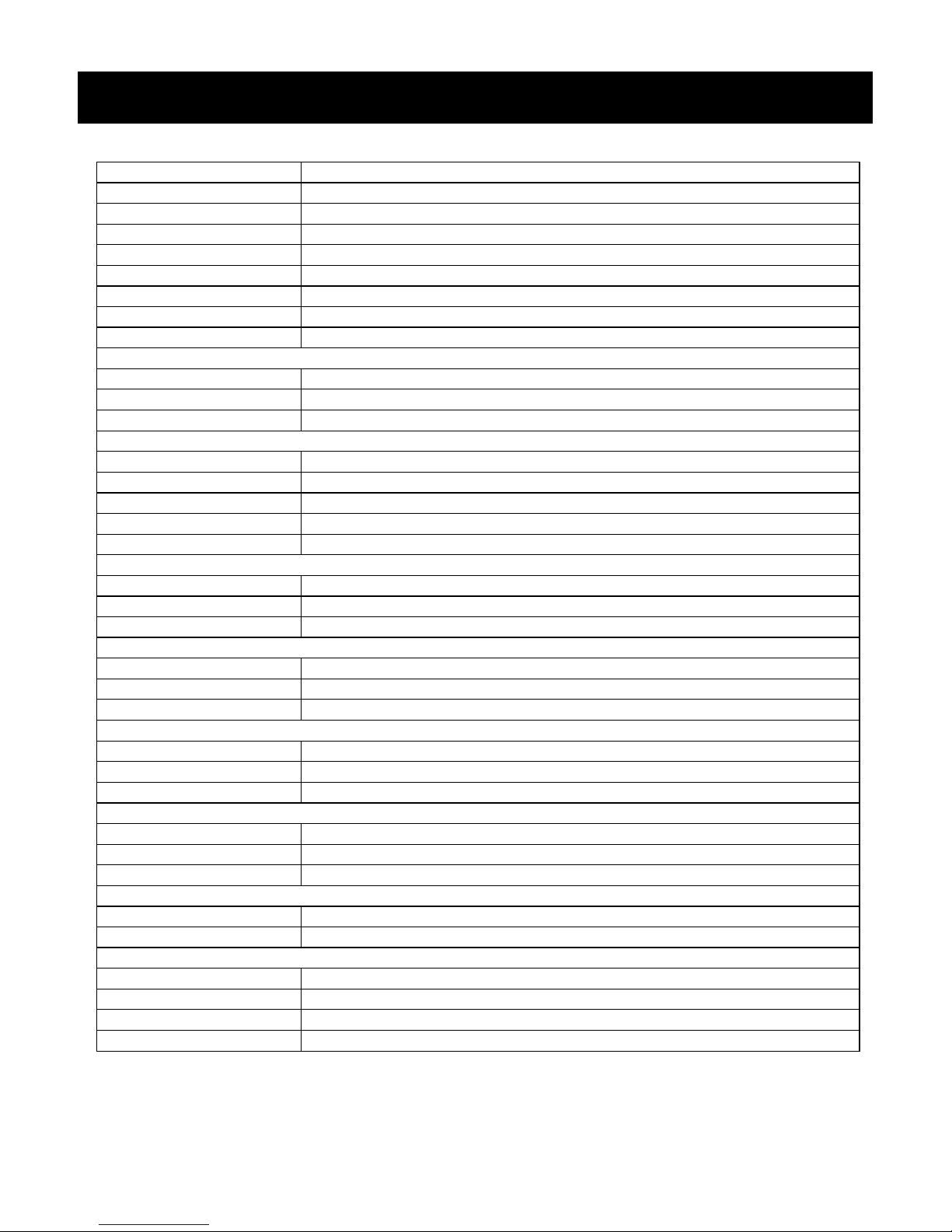
18
Channel Display Full Only
Screen size
7 inch
Active area 153.6(H) x 86.64(V)
Pixel Pitch 0.192(H) x 0.1805(V)
Resolution 800(H) x 480(V)
Viewing angle UP:70° / Down:60° / Left: 75° / Right:75°
Power source: DC9.6V ~DC32V
Contrast ratio 500:1※※※※
Brightness 450 cd/m
2
※
※※
※
AV Video In
Connector RCA Type
Input Signal 1Vpp
Impedance 75 Ohms
Camera MINI DIN In
Connector 6 PIN MINI DIN Type (Standard)
Input video signal level 1Vpp
Impedance 75 Ohms
Input audio signal level 1Vpp
Power output for camera DC12V (300mA Max)
AV Audio In
Connector RCA Type
Input audio signal level 1Vpp
Impedance 1K Ohms
Composite Video Live Out
Connector RCA Type
Output signal level 1Vpp
Impedance 75 Ohms
Audio Live Out
Connector RCA Type
Input signal level 1Vpp
Impedance 1K Ohms
CAM Out
Connector RCA Type
Input signal level 1Vpp
Impedance 75 Ohms
Dimension
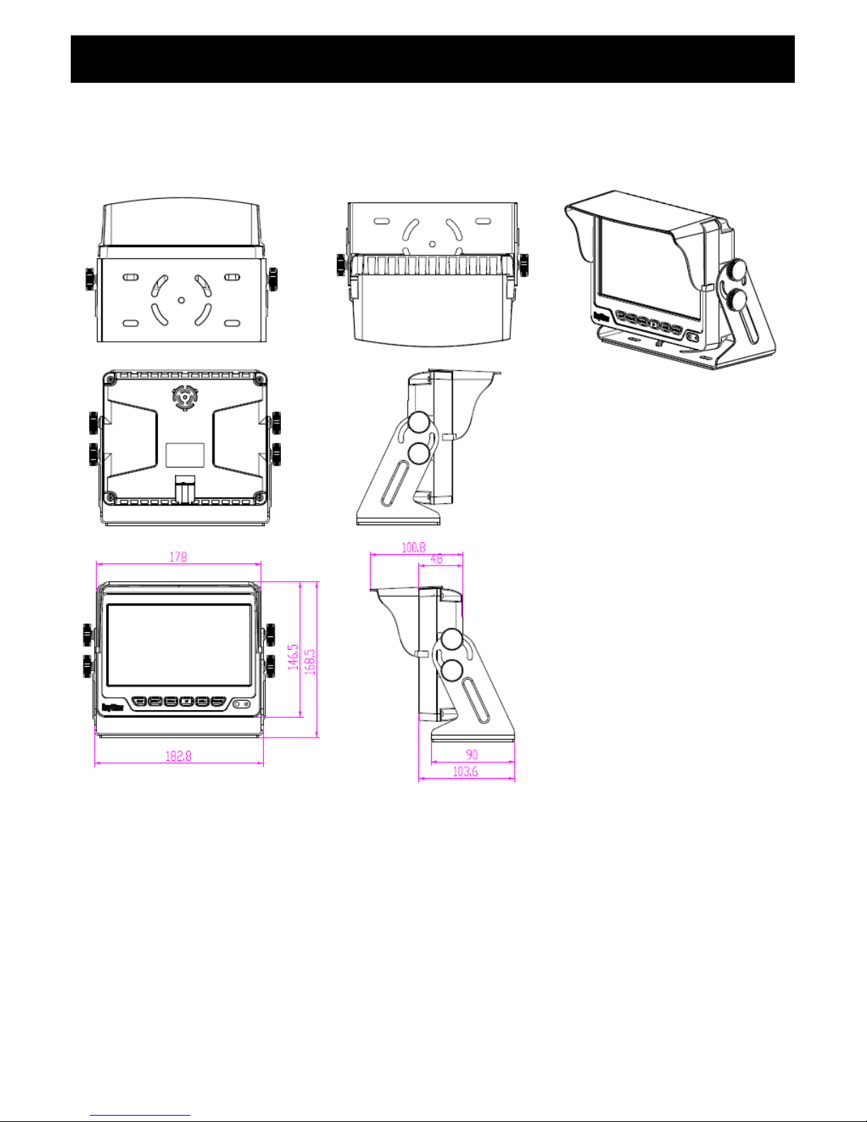
W x H x D : 182.8 x168.5 x 103.6mm
Weight N.W./G.W.: 1.5kg / 2.1kg
Environmental:
Operation temperature -20℃~ 70℃(14℉ ~ 158℉)
Storage temperature -30℃~ 80℃(-22℉ ~ 176℉)
Humidity 20%-80%
Weatherproof IPX1
The brightness※※※※ and contrast ratio specifications are from panel specification. Design and
Specifications are subject to change without notice.
Specification
Page 19
19
Attachment 1: Dimension Chart
Attachment
Page 20
20
Attachment 2: Installation Chart
85-ML074Q-A001G-B
 Loading...