

Page 1
P ROGRAMMABLE I NDICATORS AND P ROCESS
C ONTROLLERS
60 SERIES
User Guide
Version 3.0
Page 2

60 SERIES
User Guide
Version 3.0
Page 3

GSE 60 Series User Guide
Copyright © 2000 GSE Scale Systems. All rights reserved.
Published by:
GSE Scale Systems
42860 Nine Mile Road
Novi, MI 48375
USA
Information in this User Guide is subject to change without notice due to correction
or enhancement. The information described in this manual is solely the property of
GSE. No part of this manual may be reproduced or transmitted in any form or by any
means, electronic or mechanical, including photocopying and recording and sold for
any monetary figure without the express written permission of GSE.
GSE Locations Worldwide
GSE Scale Systems
42860 Nine Mile Road
Novi, MI 48375
U.S.A.
Phone: (800) 755-7875
www.gse-inc.com
GSE Canada, Inc.
617 East Lake Road
Airdrie, Alberta Canada T4B 2B8
Phone:(403) 948-9921
Fax: (403) 948-1449
Page 4

Page 5

CONTENTS
1 CHAPTER 1: INTRODUCTION................................................................ 1
COMMON WEIGHING APPLICATIONS................................................................. 1
FEATURES .........................................................................................................2
CONTROLLER DESCRIPTIONS ............................................................................2
DISPLAY ........................................................................................................... 3
KEYPAD ............................................................................................................ 5
OPTIONS ........................................................................................................... 9
SPECIFICATIONS..............................................................................................11
2 CHAPTER 2: INSTALLATION ............................................................... 15
TABLE-TOP USE..............................................................................................15
PANEL MOUNT USE ........................................................................................15
PERMANENT MOUNTING................................................................................. 15
ENVIRONMENT SUITABILITY...........................................................................15
Model 460 Outline Drawings ...........................................................................17
Model 465, 560, 562, 660, 661, 662 Outline Drawings ...................................18
Model 663 Outline Drawings ...........................................................................19
Model 665 Outline drawings ............................................................................ 20
Panel Mount Cutouts ........................................................................................21
3 CHAPTER 3: CALIBRATION ................................................................. 23
QUICK CALIBRATION ...................................................................................... 23
New Zero?......................................................................................................... 24
Last Zero?.........................................................................................................25
Temp Zero?..................................................................................................... 26
Only Zero? ...................................................................................................... 26
Cal Reset ......................................................................................................... 27
Known Load Cell? ......................................................................................... 28
SAVE CALIBRATION ........................................................................................ 29
4 CHAPTER 4: COUNTING MODE .......................................................... 31
COUNTING MODE (KEY OPERATION) ..............................................................31
Sampling to Determine a Piece Weight ............................................................ 31
Negative Sampling to Determine a Piece Weight ............................................. 32
PIECE WEIGHT ENHANCEMENT........................................................................32
KNOWN CONTAINER WEIGHT ......................................................................... 33
AUTOMATIC SCALE SELECT (WITH MORE THAN ONE WEIGHING PLATFORM)33
COUNTING MODE LISTING .............................................................................. 34
5 CHAPTER 5: ACCUMULATION MODE .............................................. 35
i
Page 6

60 SERIES I NDICATORS
PERFORMING ACCUMULATIONS...................................................................... 35
INITIALIZING ACCUMULATION TOTALS .......................................................... 35
6 CHAPTER 6: ADDITIONAL OPERATING MODES............................37
PIECE WEIGHT DATABASE MODE – APW LOOKUP .......................................37
Store APW – Store a specific APW to the database – Must Perform a sample
before using.
Get APW – Retrieve a specific APW from the database................................... 37
Print APW’s – Prints all stored records in row/column format. ...................... 38
Clear One APW – Clears current record from the database. .......................... 38
Clear All APW’s – Clears all records from the database................................. 38
TRUCK IN/OUT (MODELS 465,560,562 AND 660 SERIES)............................... 39
................................................................................................... 37
TRUCK IN...................................................................................................... 39
TRUCK OUT ................................................................................................. 39
PRINT ID’S? ................................................................................................ 39
CLEAR ONE ID............................................................................................ 39
CLEAR ALL.................................................................................................. 40
TORE TRUCK IN TARE WEIGHT .............................................................40
S
CHECK WEIGH ABSOLUTE AND PERCENTAGE OPERATION ............................. 41
Set the Hi and Lo weights (460) .......................................................................41
Use Check Weigh (460) .................................................................................... 41
Set the Hi and Lo weights (465,560,562 and 660 Series)................................. 41
Use Check Weigh.............................................................................................. 41
BATCHING OPERATION (465,560 AND 562) - FILL ......................................... 42
Setting setpoints, preact, and dribbles.............................................................. 42
Batching............................................................................................................ 42
7 CHAPTER 7: TIME AND DATE (CLOCK FEATURE)........................43
VIEWING TIME AND DATE .............................................................................. 43
ENTERING A NEW TIME AND DATE (EXCLUDING MODEL 460) .......................43
ENTERING A NEW TIME AND DATE (MODEL 460)........................................... 44
8 CHAPTER 8: LEGAL-FOR-TRADE........................................................45
OIML AND INTERNATIONAL OPERATION .......................................................45
NTEP .............................................................................................................46
Enabling NTEP Operation ...............................................................................46
NTEP Custom Setup .........................................................................................47
Sealing and Audit Trails................................................................................... 49
9 CHAPTER 9: TROUBLESHOOTING .....................................................57
OPERATIONAL MODE ERROR MESSAGES........................................................ 57
ii
Page 7

C HAPTER 1:INTRODUCTION
SETUP MODE ERROR MESSAGES.....................................................................58
HARDWARE PROBLEM ERROR MESSAGES ...................................................... 59
CALIBRATION ERROR MESSAGES....................................................................60
GENERAL ERROR MESSAGES ..........................................................................61
MISCELLANEOUS MESSAGES ..........................................................................62
COMMUNICATIONS ERROR MESSAGES............................................................ 62
TROUBLE-SHOOTING ......................................................................................63
SERVICE.......................................................................................................... 63
iii
Page 8

Page 9
1CHAPTER 1: INTRODUCTION
GSE 60 Series programmable indicators come standard with a number of
features that make them the most versatile and powerful systems in their
price class. Accurate and durable, 60 Series controllers will provide you
with years of quality weighing service even in the most demanding industrial
environments.
This User Guide contains basic operating information. Subjects covered
include controller installation, operation modes, custom transmits, variable
or string operations, the clock feature, legal-for-trade issues, and
troubleshooting.
Subjects such as the Setup Mode and the macro programming language are
beyond the scope of a User Guide. For more detailed operating instructions,
a 60 Series Technical Reference Manual is available. Contact your GSE
Distributor for more information.
COMMON WEIGHING APPLICATIONS
Typical weighing applications for GSE 60 Series controllers include:
• Small parts weighing
• Large parts weighing
• Parts counting
• Vehicular truck loading (truck in
/ truck out)
• Tank weighing
• Process control
• Inventory control
• Order picking
• Floor and hopper scales control
• Conveyor weigh systems control
• Batching (mixing)
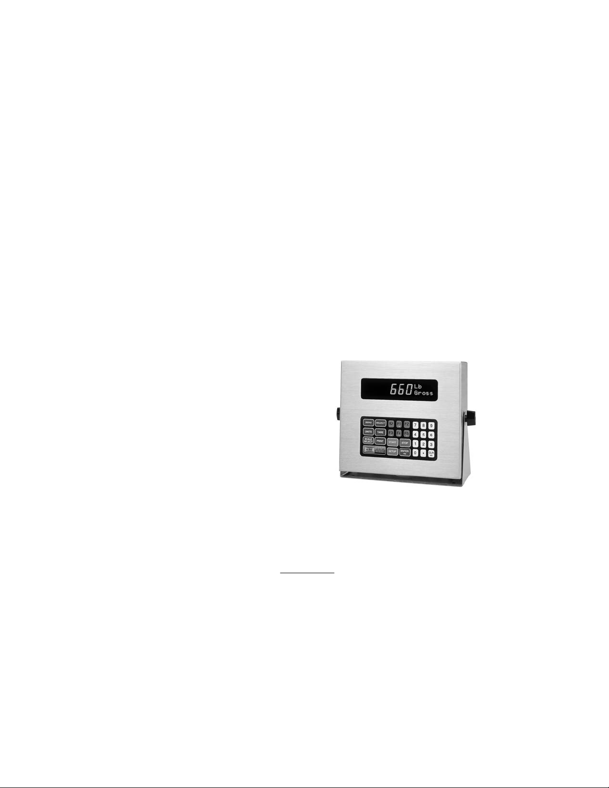
Figure 1: Model 660
1
Page 10

60 SERIES I NDICATORS
FEATURES
GSE 60 Series controllers share the following standard features:
• Sealed elastomer keypad for protection against harsh environments
• Capability to power as many as 14 350-ohm load cells for demanding
applications (12 350-ohm load cells on 460 and 465)
• AC/DC power operation
• Front panel calibration and linearization execution
• Full scale response time from 0.06 to 8 seconds
• Selectable weighing units: pounds, kilograms, ounces, grams, etc.
• Programmable RS-232 communications software
• Remote display support capability
• Expandable memory for increased data storage
• Battery-backed time and date clock
• Weighing increments of 1, 2, or 5 units, from .00001 to 500
CONTROLLER DESCRIPTIONS
All 60 Series models excluding the 663 come with a swivel bracket for
positioning on a tabletop or mounting to any fixed surface. They are also
available in panel-mount versions.
A stainless steel NEMA 4X enclosure for washdown environments comes
standard on all 60 Series models. The model 663 is also available in a
powder coat mild steel enclosure.
GSE offers many options to enhance the 60 Series of controllers. The
number of options that can be used varies among the different models.
See the Specifications section on page 11 for enclosure dimensions.
2
Page 11

C HAPTER 1:INTRODUCTION
DISPLAY
Display types differ according to model. The table below describes the
display(s) offered for each controller.
Table 1: 60 Series Displays
Model Display
460, 465, 560
660
661 4-line by 20-character alphanumeric VF display
562, 662 240 x 64 backlit LCD graphic, 3 font sizes
663 Available in two versions:
665 Available in two versions:
The vacuum fluorescent (VF) display is divided into two sections: a large,
six-digit numeric area to the left, and a smaller, two-line-by-five-character
dot matrix area to the right.
6 digit, Vacuum Florescent display (VFD)
0.75” (19mm) height with 2X5 matrix
(8mm)
• 6 digit, Vacuum Florescent display (VFD) and
4x20 character alphanumeric VF display
OR
• 240x128 backlit LCD display
• 6 digit, Vacuum Florescent display (VFD) and
4x20 character alphanumeric VF display
OR
• 240x128 backlit LCD display
The large digit area displays numeric data, such as Gross Weight, Net
Weight or Tare Weight. The dot matrix area has several purposes:
• The first two characters on the upper line show the weighing units of the
displayed data.
• The last three characters on the upper line show a CENTER ZERO (->0< --) condition at times.
• The lower line of the dot matrix area specifies the type of data, such as
Gross, Net, Tare, etc.
The dot matrix area also displays specific messages during controller
operation and setup.
3
Page 12
60 SERIES I NDICATORS
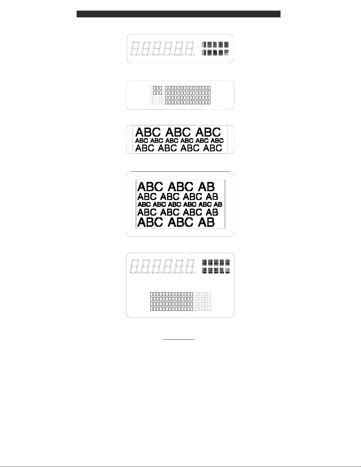
Figure 2: 6 Digit Vacuum Fluorescent Display (VFD)
Figure 3: 4x20 Vacuum Fluorescent Display (VFD)
Figure 4: 240x64 Backlit LCD Display
Figure 5: 240x128 Backlit LCD Display
Figure 6: 6 Digit VFD and 4x20 VFD
4
Page 13
C HAPTER 1:INTRODUCTION
KEYPAD
A sealed elastomer keypad comes standard on all 60 Series controllers. A
TTL alpha keypad is also available as an option on the model 663 controller.
For more information on the alpha keypad option, please refer to the 60
Series Technical Reference Guide.
Detailed descriptions of each key and its associated function follow below.
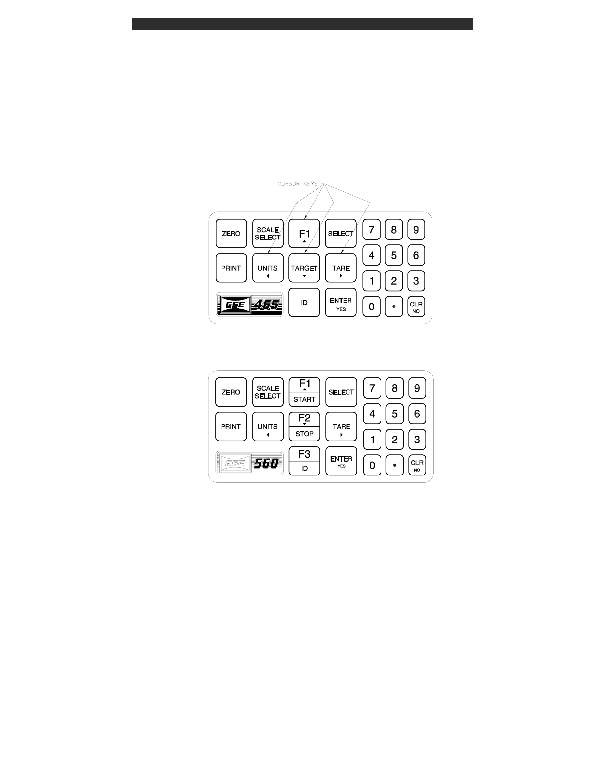
Figure 7: 465 Keypad
Figure 8:560/562 Series Keypad
5
Page 14

60 SERIES I NDICATORS
Figure 9: 660 Series Keypad
ZERO Press [ZERO] to zero the current quantity/weight reading.
When the meter is at Center Zero center-of-zero indication
will appear on the upper line of the dot matrix display. If a
Custom Unit’s name is greater than 2 characters, the Center
Zero indication is not displayed. If in the quantity mode,
pressing [ZERO] will set the current mode to a gross zero
quantity. If in the Weigh Mode, pressing [ZERO] sets the
current mode to Gross Weight.
UNITS
Pressing [UNITS] from the Weigh Mode will toggle the
displayed units through the available selections. Converted
units are automatically rounded to the appropriate
increment.
SELECT Pressing [SELECT] will toggle you through the Net
Weight, Tare Weight and Gross Weight or other enabled
operating modes.
TARE Pressing [TARE] by itself will perform an auto-tare. A Net
Zero is then displayed. You can enter a known Tare weight
by keying in the number and pressing [TARE]. In either
case, the indicator will be placed in the Net Mode, unless
you are in the Tare Mode.
ENTER/YES Press the [ENTER] key following certain numeric entries.
Doubles as a [YES] key for answering operator prompts.
PRINT
ID
Press to send data to a printer, computer or other device.
Used for entering ID numbers.
[F1c] The [F1c] key is used as an up arrow key for scrolling or
as a function key (such as accessing a menu or starting a
process). Not available on Model 460.
6
Page 15

C HAPTER 1:INTRODUCTION
[F2] The [F2] key is used as a function key (such as accessing a
menu or starting a process). 560 and 660 Series only. Not
available on Model 460 or Model 465.
[F3e] The [F3e] key is used as a left arrow key for scrolling or
as a function key (such as accessing a menu or starting a
process). Not available on Model 460 or Model 465.
[F4d] The [F4d] key is used as a down arrow key for scrolling or
as a function key(such as accessing a menu or starting a
process) . Not available on 460 or 560 Series.
[F5f] The [F5f] key is used as a down arrow key for scrolling or
as a function key (such as accessing a menu or starting a
process) . Not available on 460 Series or 560 Series.
TARGET
Only available on the Model 465. Used as a function key
and a down arrow key.
START The [START] key is used as a function key. 560 and 660
Series only. Not available on 460 Series.
STOP The [STOP] key is used as a function key. 560 and 660
Series only. Not available on 460 Series.
SETUP The [SETUP] key is used as a function key. 660 Series
only. Not available on 460 Series or 560 Series.
0 - 9 & .
Press the numeric keys to enter numeric values 0 through 9.
Press [.] to establish a decimal point or perform an
accumulation in the weigh or count mode. Not available on
Model 460.
CLR
Press this key to clear a numeric entry mistake prior to
entering it into memory. Also doubles as a [NO] key for
answering questions.
SCALE
SELECT
Pressing [SCALE SELECT] will toggle through all the
enabled scale inputs. Not available on Model 460.
7
Page 16
60 SERIES I NDICATORS
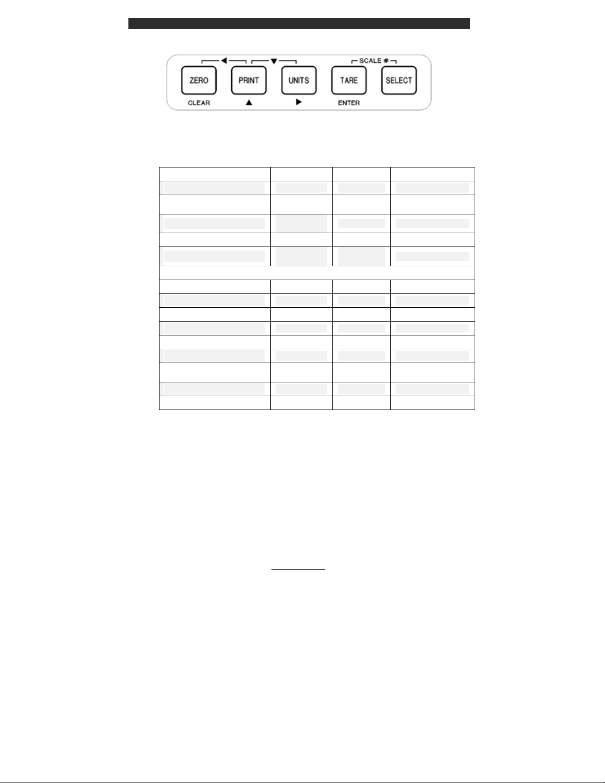
Figure 10: 460 Keypad
Table 2: 460 Key Functions
KEYPRESS GROSS/NET QTY OTHER MODES
[ZERO / CLEAR]
[PRINT]
[UNITS]
[TARE / ENTER]
[SELECT]
Zero Scale Zero Quantity ZERO * CLEAR
Print custom
transmit
Toggle though
enabled units
Tares Scale Tares Scale ENTER
Selects
Parameters
Print custom
transmit
N/A
Selects
Parameters
Character Entry
Space ►
SELECT
†
▲
Multiple Key Combinations
[ZERO] + [PRINT]
[ZERO] + [TARE]
[ZERO] + [UNITS]
[PRINT] + [UNITS]
[PRINT] + [SELECT]
[TARE] + [SELECT]
[UNITS] + [SELECT]
[UNITS] + [TARE]
[PRINT] + [TARE]
◄ ◄ ◄
N/A N/A Clear Entry
N/A N/A N/A
▼ ▼ ▼
ext. res. OIML ext. res. OIML ext. res. OIML
Scale Select Scale Select Move backwards
Performs an
Accumulation
N/A N/A N/A
N/A N/A N/A
Performs an
Accumulation
ENTER
* = No entry in progress
= Entry in progress
8
Page 17

OPTIONS
Numerous hardware options that maximize the capabilities and functions of
the standard 60 Series controllers are available. These options can be
installed by your GSE distributor when you order your controller or added
later. All options must be installed by your GSE distributor or a qualified
technician. Please do not return the controller to GSE for installation of
options. Consult your GSE products distributor for installation instructions.
4-Position I/O Board
60 Series supports the eight following 4-position I/O boards:
• Low Voltage AC 2 input 2 output
• High Voltage AC 2 input 2 output
• AC 4 output
• Low Voltage AC 4 input
• High Voltage AC 4 input
• DC 2 input 2 Output
• DC 4 output
• DC 4 input
16-Position I/O Board
The 16-position I/O board can be used in combination with the 4-position
boards listed above. As many as 128 I/O circuits can be configured.
Alpha Keypad (663 only)
Allows easy entry of alphanumeric characters.
Alphanumeric Serial Keyboard Converter Kit
Adapts PC keyboard to the indicator serial port (includes keyboard).
Analog Output
Up to 8 analog output cards can be added for analog output signals of each
scale value or any other independent variable.
Database
Adds capability for creating database records, consisting of fields, for data
storage and retrieval. Battery-backed SRAM increases internal storage to
256K, 1M, or 2M.
C HAPTER 1:INTRODUCTION
9
Page 18

60 SERIES I NDICATORS
DeviceNet Module
Provides a communication path between multiple end-points (Devices). The
GSE indicator will act as a slave on the network device layer.
Dura-Shield
A clear weatherable film lexan that adheres over the keypad and display.
Recommended when high-pressure washdown, petroleum distillates or harsh
cleaning agents are present. (Not available for the 663).
Ethernet Module
Communicate via internet or intranet connection.
Memory Expansion (Not available for 460 Series)
An 8Kmemory chip can replace each of the two standard 2K memory chips,
increasing internal E2 memory from the standard 4K to 16K maximum.
Multi-Scale
Enables the use of as many as seven additional scale platforms per
controller.
Network Module
Addressable RS-485 network card. Full or half duplex.
Profibus Module
Allows joint operation of several systems with their distributed peripherals
on one bus. The GSE indicator acts as a slave on the network line.
SCR Module
DIN rail mount controller suitable for controlling AC devices such as
vibratory feeders.
Severe Transient Voltage Suppression
Protects the controller from power line transient damage.
Splash Guards
A clear flexible vinyl cover for use in harsh environments. It will keep the
indicator well protected and looking like new.
10
Page 19

C HAPTER 1:INTRODUCTION
SPECIFICATIONS
Performance
• Full Scale Selectable
• Resolution 100,000 displayed (+/-500,000 internal)
• Display Update Selectable 0.05-20 seconds
• A/D Conversion 60 Hz
• Non-Linearity 0.005% of full scale (input dependent)
• Zero Track 0.05-20.0 displayed divisions
• Zero Range Selectable from 0.01-100% of full scale
• Calibration Selectable, 5 multi-point calibration for
linearization
• Division Size .00001 through 500
• Warranty 2 year
Electrical
• Power input 90-250 VAC, 50/60 Hz; 10-32 VDC
• Fuse 0.8 amp time lag
Load Cell Input
• Connections 4 lead or 6 lead with sense, jumper selectable
• Power 14 350-ohm cells (560 and 660 Series)
• Power 12 350-ohm cells (460 Series)
• Signal Range 0.1 to 20 mV/V at full scale
• Excitation 10 VDC, short circuit protected
• Current 400 mA maximum
Communications
• Bi-directional RS-232 serial ports
• Independent custom transmit tables for labels, reports, transmitting
control characters, etc.
• Transmit output: continuous transmit, on request, motion inhibited
• Selectable baud rate
• Selectable protocol
11
Page 20

60 SERIES I NDICATORS
• Selectable data formatting
Display
• Vacuum fluorescent, 0.75 in. high digits
• 240x64 LCD display, 5 in. x 1.34 in. usable area
• 240 x 128 LCD display, 4.72 in. x 2.52 in. usable area
• Four-line by 20-character alphanumeric display, 0.20 in. high digits
• Increments 1,2, 5, 10, 20, 50, 100, 500
• Selectable decimal point
• Display values -99,999 through 999,999
• Polarity "-" sign to left of most significant active digit
• Status indicator 10-character dot matrix prompting display
Enclosure Dimensions
Model Width Height Depth
465/560/562//660/661/662
460
460 Panel Mount
465/560/562/660/661/662
Panel Mount
663
663 Big Box
665
mm =millimeter; in = inch
*Includes mounting stand.
**Includes mounting flange.
11 in*
(279 mm)
11 in*
(279 mm)
10 in**
(254 mm)
10 in**
(254 mm)
16.18 in**
(411 mm)
24 in**
(609 mm)
11.07 in*
(281.20 mm)
12
9 in*
(228 mm)
8 in*
(203 mm)
7 in**
(177 mm)
9 in**
(228 mm)
22.5 in**
(571.5 mm)
32 in**
(812 mm)
12.16 in*
(308.9 mm)
4.4 in*
(112 mm)
4 in*
(101 mm)
4 in**
(101 mm)
4.4 in**
(112 mm)
9.28 in**
(235.7 mm)
9.28 in**
(235.7 mm)
4.70 in*
(119.4 mm)
Page 21

C HAPTER 1:INTRODUCTION
13
Page 22

Page 23

2CHAPTER 2: INSTALLATION
This chapter outlines the basic installation of the 60 Series instruments.
Please take the time to review these important guidelines.
IMPORTANT!
The 60 Series indicators do not include an on/off switch, and therefore
must be installed near a power outlet socket that is easily accessible and in
keeping with UL/CSA safety standards.
TABLE-TOP USE
All models excluding the model 663 have been designed with a swivel
bracket, which lets you tilt the instrument face to any desired angle. When
the instrument is placed on a table, the non-slip rubber feet prevent
scratching and slipping across the surface when keys are pressed.
PANEL MOUNT USE
All models excluding the Model 663 are available in panel mount versions.
When properly installed, the units are suitable for washdown environments.
The panel mount version functions identically to the table top version. The
only difference between the two package types is the mechanical aspects of
the enclosure and the positioning of the main board and display. Refer to the
60 Series Technical Reference Manual for further panel mount version
installation procedures and available options.
PERMANENT MOUNTING
Refer to pages 21 - 24 for panel mount cutout and mounting hole
dimensions.
ENVIRONMENT SUITABILITY
60 Series instruments are supplied in a NEMA 4X (IP66) enclosure and may
be used in a washdown environment. Care must be taken to ensure that the
AC power socket outlet is properly protected.
The keypad is made of silicon rubber. It may be cleaned periodically with a
soft damp non-abrasive cloth. The display window is made from a
15
Page 24

60 SERIES I NDICATORS
polycarbonate material, which may scratch due to aggressive cleaning. Care
must be taken to avoid such damage.
Connections from the load cell to the single channel input require gaining
access to J1 inside the sealed enclosure. In addition, peripherals and
options can be interfaced to 60 Series instruments by means of connections
within the enclosure. However, physically accessing the unit may void the
warranty. Refer to the Technical Reference Manual or contact your local
GSE distributor.
Calibrating the unit requires entering the Setup Mode and selecting the
calibration parameters specific to your application needs. Contact your
local GSE distributor for calibration service.
16
Page 25

C HAPTER 2:INSTALLATION
MODEL 460 OUTLINE DRAWINGS
Figure 11: 460 Standard Enclosure
Figure 12: 460 Panel Mount Enclosure
17
Page 26

60 SERIES I NDICATORS
MODEL 465, 560, 562, 660, 661, 662 OUTLINE DRAWINGS
Figure 13: Standard Enclosure (excluding 460, 663, 665)
Figure 14: Panel Mount Enclosure (excluding 460, 663, 665)
18
Page 27

C HAPTER 2:INSTALLATION
MODEL 663 OUTLINE DRAWINGS
Figure 15: Model 663 Standard Enclosure
Figure 16: Model 663 Big Box Enclosure
19
Page 28

60 SERIES I NDICATORS
MODEL 665 OUTLINE DRAWINGS
Figure 17: Model 665 Standard Enclosure
Figure 18: Model 665 Panel Mount Enclosure
20
Page 29

C HAPTER 2:INSTALLATION
PANEL MOUNT CUTOUTS
Figure 19: Model 460 Panel Mount Cutout
Figure 20: Model 465, 560, 562, 660, 661, 662 Panel Mount Cutout
21
Page 30

60 SERIES I NDICATORS
Figure 21: Model 665
22
Page 31

3CHAPTER 3: CALIBRATION
The 60 Series indicators can be calibrated several ways. The following
method is a quick calibration procedure and assumes that the necessary
parameters are selected before the actual calibration is performed (i.e. full
scale value, graduation size, etc.). Your local GSE distributor will normally
set up these parameters.
QUICK CALIBRATION
A certified weight is required to perform a calibration. Serious
inaccuracies could result from using non-certified standards for calibration.
To access calibration on the Model 460:
• From the Weigh Mode press
[ZERO]+[SELECT]
[ZERO] [PRINT] [UNITS] [TARE/ENTER]
To access calibration on all other 60 Series indicators:
• From the Weigh Mode press
[100] [SELECT] [5 4 3 2 1] [ID] [ENTER]
The controller will briefly prompt you with QUICK CAL! And then New
Zero?. If multiple scales are enabled, the controller will prompt you with
Keyin Scl #. Key in the scale number being calibrated and press [ENTER].
Use the [PRINT] and [UNITS] keys to enter the scale number on the Model
460. Refer to Table 2: 460 Key Functions on page 8. After the scale number
is entered the New Zero? prompt will be displayed.
Press the [SELECT] key to toggle through the available calibration
selections, and [ENTER] when the desired calibration method is displayed.
Press [ENTER] to begin calibration when the desired calibration selection is
displayed. Pressing the [CLR] key at any point in the calibration routine will
back you up one step.
23
Page 32

60 SERIES I NDICATORS
The calibration selections are as follows, starting with New Zero?:
• New Zero?
• Last Zero?
• Temp Zero?
• Only Zero?
• Cal Reset
• Known Load Cell
•
NEW ZERO?
New Zero? is the selection for establishing the first or a new calibration. If
New Zero? is selected, the controller displays the dead load (which might
not be in precise units) that is present on the scale. The controller assumes a
“NO LOAD” condition.
Remove the load, and press [ENTER]. As soon as [ENTER] is pressed, a
new zero is established. This is reflected on the main display with the
prompt Adj’g Zero followed by the prompt Keyin CalWt.
At this point, the controller is waiting for the actual calibration value to be
entered. Place the calibration weight on the platform, key in the weight
value, and press [ENTER].
If you key in a cal weight and press [ENTER] without adding any weight
since the last calibration weight, the controller will prompt you to add
CalWT. Add the weight and press [ENTER].
NTERING NUMERIC VALUES
E
Where appropriate, you can use the numeric keypad to enter numeric values.
Use the [PRINT] and [UNITS] keys to enter numeric values on the Model
460. Refer to Table 2: 460 Key Functions on page 8. If an error is made
while entering data, press [CLR] before you press [ENTER]. The controller
will perform the calibration, display the value of the calibration weight, and
prompt CAL OK?. At this point, you can check the accuracy of the
calibration by weight without leaving the Calibration Mode.
• If the calibration was accurate, press [ENTER].
• The controller will prompt you to save the new calibration plus any
other changes you have made. Press [ENTER] twice to save and exit.
24
Page 33

C HAPTER 3:CALIBRATION
• If the calibration is not accurate, press [CLR].
The controller will return to the New Zero? prompt. Repeat the above
steps to calibrate.
If the calibration weight was less than 5% of capacity, or if there was a
large change in the calibration, the controller prompts ReCal Req’d. Press
[ENTER] and repeat the calibration, or press [CLR] to obtain the CAL
OK? prompt as described above and override the re-calibration
requirement.
LAST ZERO?
The Last Zero procedure allows recalibration of the weighing device using
an existing test load. This is especially beneficial when checking high
capacity applications such as tank weighing to minimize the task of placing
and removing test weights.
1. Remove all weight from the scale
2. Press [ZERO] to zero the scale in the weigh mode.
3. Apply the calibration test weight.
4. Access the Calibration Mode (see page 23).
5. Use the [SELECT] key to toggle to Last Zero?.
6. At the Last Zero? prompt, the [ENTER] key is pressed.
7. Key in the calibration weight value in terms of the default calibration
units and press [ENTER]. For the Model 460, use the [PRINT] and
[UNITS] keys to enter numeric values. Refer to Table 2: 460 Key
Functions on page 8.
8. After establishing span, Cal OK? is displayed. Or if Recal ??? is
displayed, repeat the calibration process.
9. Press [ENTER] to save the calibration.
10. At the prompts Save Mods? and Enter = Save are displayed, [ENTER]
is pressed to save the new calibration factors.
11. At the Enter = Exit prompt, [ENTER] is pressed again and the
controller returns to the Weigh Mode.
25
Page 34

60 SERIES I NDICATORS
TEMP ZERO?
Temp Zero? is used to recalibrate without establishing a new zero. In some
applications you might want to perform a calibration without removing the
currently applied load. This is particularly useful in tank weighing
applications where it is both time-consuming and costly to drain the tank
being weighed.
During the calibration procedure, at the Temp Zero? prompt you press
[ENTER]. This action causes the controller to zero the displayed weight
temporarily so additional weight can be added to assure system calibration.
The zero determined during the previous calibration is not affected.
1. Access the Calibration Mode (see page 23).
2. Use the [SELECT] key to toggle to Temp Zero?.
3. At the Temp Zero? prompt, press [ENTER].
The displayed value will zero out.
4. Apply the calibration weight.
5. Key in the value of the calibration weight: for example, 1 0 0 0
[ENTER]. For the Model 460, use the [PRINT] and [UNITS] keys to
enter numeric values. Refer to Table 2: 460 Key Functions on page 8.
The numeric display should show the entered value.
6. Remove the calibration weight. The display should return to zero. If the
display reads as specified, at the Cal OK? prompt press [ENTER]. To
repeat the calibration process, press [CLR], and then repeat steps 2
through 5.
7. Save the newly determined calibration weight: At the Enter = Save
prompt, press [ENTER]
8. To return to the Weighing Mode, at the ENTER = EXIT prompt, press
[ENTER].
ONLY ZERO?
Only Zero is used to establish a new calibration zero without affecting the
span. This is useful for correcting changes to the scale’s dead load, for
example in tank weighing applications where the re-zero parameter (P118) is
set very low in order to prevent inadvertent re-zeroing. A build-up of sludge
can be zeroed out in this manner.
26
Page 35

C HAPTER 3:CALIBRATION
1. Remove all weight from the scale.
2. Access the Calibration Mode (see page 23).
3. Press [SELECT] to toggle to the Only Zero? routine.
4. At the Only Zero? prompt, press [ENTER].
The displayed value zeroes out. Adj Zero! is displayed briefly, followed
by CAL OK?.
5. Press [ENTER] to accept the newly established zero, or [CLR] to
repeat the calibration.
9. At the Enter = Save prompt, press [ENTER]
10. To return to the Weighing Mode, at the ENTER = EXIT prompt, press
[ENTER].
C
AL RESET
Cal Reset may be necessary when an over-load or under-load condition
exists, preventing the completion of the calibration process. Calibration
Reset adjusts the zero and gain factors of the A/D amplifier to factory
default values for maximum sensitivity.
After performing a calibration reset, a complete recalibration is required.
The effects of a calibration reset do not take effect until the indicator is
recalibrated and calibration information has been saved.
If Code 02 (under-load) or Code 03 (over-load) is displayed during
calibration, press [CLR] to perform a calibration reset.
When reset, these parameters are adjusted to the lowest possible values.
Contact your GSE Distributor regarding Information Parameters for a more
detailed explanation on the gain factors.
Normally, a Cal Reset is performed if the amplifier is locked in at an
extremely high gain factor and will not allow a new calibration to be
performed.
1. Access the Calibration Mode (see page 23).
2. Press [SELECT] to toggle to the Cal Reset.
27
Page 36

60 SERIES I NDICATORS
Once the Cal Reset is performed, the controller returns to the New Zero?
prompt. Press [SELECT] to toggle to the desired calibration routine.
Following a Cal Reset, a re-calibration should be performed before exiting
the calibration or Setup Modes. The reset will not be saved unless a recalibration is performed and changes are saved.
KNOWN LOAD CELL?
Known Load Cell is used to calibrate without test weights. The exact full
scale mV/V rating must be known for each load cell. All load cells must be
of the same full scale capacity. This procedure works best for hopper scales
where weight is evenly distributed and signal trimming is not required.
1. Access the calibration mode (see page 23).
2. Press [SELECT] to toggle to the Known LCOut routine.
3. Press [ENTER] at the Known LCOut prompt to display #of LC.
The number of load cells specified during the last calibration will also
be displayed. A value of zero (0) indicates that this calibration method
has not yet been performed.
4. Key in the number of load cells and press [ENTER]. For the Model
460, use the [PRINT] and [UNITS] keys to enter numeric values. Refer
to Table 2: 460 Key Functions on page 8.
- or -
Press [ENTER] to accept the displayed value.
5. The display prompts LC#x mVv (where ‘x’ is the load cell number) and
then shows the mV/V value (0.1 Æ 5.0) last entered for this load cell.
6. Key in the load cell’s mV/V value and press [ENTER]. For the Model
460, use the [PRINT] and [UNITS] keys to enter numeric values. Refer
to Table 2: 460 Key Functions on page 8.
- or -
Press [ENTER] to accept the displayed value.
7. Steps 5-6 will be repeated for as many load cells as specified in step 4.
8. The display prompts LC FS showing the value last entered for the load
cell full scale.
28
Page 37

C HAPTER 3:CALIBRATION
9. Key in the full scale capacity for the load cell(s) and press [ENTER].
For the Model 460, use the [PRINT] and [UNITS] keys to enter
numeric values. Refer to Table 2: 460 Key Functions on page 8.
- or -
Press [ENTER] to accept the displayed value.
10. The display briefly shows Updtg Gains as it updates the gain values,
then prompts CurWt Zero?.
11. Press [ENTER] to establish the current input signal as the zero
reference.
- or -
Press [SELECT] to display Zero=0mVv?. Press [ENTER] to use a
0mV/V output as the zero reference.
- or -
Press [SELECT] to display Keyin CurWt. Key in the known gross
weight already applied to the scale and press [ENTER].
- or -
Press [CLR] to bypass the zeroing option.
12. The display shows CAL OK? suggesting that the calibration is
acceptable.
Accept the calibration by pressing [ENTER] at the CAL OK? prompt.
- or -
Repeat the calibration by pressing [CLR] at the CAL OK? prompt.
13. Once the calibration is accepted, press [ENTER] at the ENTER=SAVE
prompt and again at the ENTER=EXIT prompt to save the new
calibration and exit the calibration mode.
- or -
To exit the calibration mode without
[CLR] at the ENTER=SAVE prompt. Then press [ENTER] at the
ENTER=UNDO
exit the calibration mode.
prompt and again at the ENTER=EXIT prompt to
saving the new calibration, press
SAVE CALIBRATION
The indicator will perform the calibration, display the value of the
calibration weight, and display the prompt, CAL OK?. At this point, you can
29
Page 38

60 SERIES I NDICATORS
check the accuracy of the calibration by weight without leaving the
Calibration Mode.
If the calibration was accurate, press [ENTER]. The indicator will prompt
you to save the new calibration plus any other changes you made. Press
[ENTER] to save, then [ENTER] again to exit. If the calibration is not
accurate, press [CLR]. The indicator will return to the New Zero? prompt.
If the calibration weight is less than 5% of capacity or if there is a large
change in the calibration, the indicator will prompt ReCal Req'd. Press
[ENTER] and you will be returned to the beginning of the calibration
selections, or press [CLR] to obtain the CAL OK? prompt as described
above and override the re-calibration requirement.
A variation of the calibration process is the linearization procedure.
Linearization is useful in improving the absolute accuracy of large-capacity
systems, which often exhibit poor linearity. This feature is documented in
the 60 Series Technical Reference Manual.
30
Page 39

4CHAPTER 4: COUNTING MODE
The front panel keys on the 60 Series take on different functions depending
on the selected mode. This chapter will define the front panel key operation
for the Counting Mode.
COUNTING MODE (KEY OPERATION)
To activate the counting operation, the indicator must be in the Quantity
mode. To access the Quantity mode on a Model 460, the quantity mode must
be in the selectable modes of instrument operation. Simply press the
[SELECT] key to step through all enabled modes of instrument operation.
The Quantity mode may be accessed directly by pressing [30] [SELECT]
(not available on the Model 460).
SAMPLING TO DETERMINE A PIECE WEIGHT
Although the sampling process may be performed in a number of ways, the
recommended method is to first access the Quantity mode, then place an
empty box or empty container on the scale platform, and press [ENTER].
The first time a sample is performed, the display will read Must Sampl and
press [ENTER]. The indicator will then perform an auto-tare resulting in a
zero net weight. The display will prompt you to Add xx, where the "xx" is
the sample quantity of parts (sample size)—the manufacturer default setting
is 10 pieces. Add the requested number of parts to the scale and press the
[ENTER] key.
If the sample's total weight was sufficient, the piece weight will be
calculated and the sample quantity will be displayed. Otherwise, you may
be prompted to add additional parts. The exact prompts will depend on
whether the auto-enhance and/or minimum accuracy assurance features have
been enabled. The minimum amount of weight required for the sample
routine to meet the selected accuracy requirements for the specified scale
capacity is considered.
If the weight of the sample is un-detectable or barely detectable then the
message Code 32 ADD MORE! is displayed briefly. This will most often
occur when the [ENTER] key is pressed without adding any parts. If the
parts were in fact placed on the scale, either the parts are too light to count
on that capacity platform or a much larger quantity of parts must be hand
counted in order to perform the sample.
31
Page 40

60 SERIES I NDICATORS
EGATIVE SAMPLING TO DETERMINE A PIECE WEIGHT
N
In order to perform a negative sample routine, access the Quantity mode,
place a full or partially full container of parts on the scale, and press
[ENTER].
The indicator will then perform an auto-tare resulting in a zero net weight.
The display will then prompt you to Add xx where the "xx" is the sample
size. In this case, the prompt Add xx actually means take parts from the
container. Proceed to remove the requested number of parts, and then press
the [ENTER] key. If the sample's total weight was sufficient, the piece
weight will be calculated and the sample quantity will be displayed (-10
parts). Otherwise, you may be prompted to take additional parts. The exact
prompts will depend on whether the auto-enhance and/or minimum accuracy
assurance features have been enabled.
If the weight of the sample removed was un-detectable or barely detectable
then the message Code 32 ADD MORE! is displayed briefly. This indicates
that more weight must be removed adding to the overall sample weight.
This occurs most often when the [ENTER] key is pressed without taking out
any parts. If the parts were in fact taken from the scale, either the parts are
too light to count on that capacity platform or a much larger quantity of parts
must be hand counted out in order to perform the sample.
The first method is recommended to avoid the possibility that inappropriate
tare weights may affect the piece weight calculation.
When the Quantity mode is accessed and the residing piece weight value is
“0.00”, the prompt Must Sampl will be displayed. Press the [ENTER] key
to proceed with the sampling to determine a piece weight.
PIECE WEIGHT ENHANCEMENT
The presence of this feature depends on the internal setup of your
controller. It is intended for the accurate counting of extremely light parts.
1. Access the quantity mode.
2. Place an empty container on the platform (optional).
32
Page 41

C HAPTER 4:COUNTING M ODE
3. Press [ENTER]. The indicator tares to a zero net weight. The display
shows the current net weight and the prompt: Add 10.
4. Place the specified number of parts on the scale.
5. Press [ENTER]. The indicator then calculates the piece weight of the
sample parts and momentarily displays the maximum number of parts
which may be added for a piece weight enhancement to occur. The
minimum achieved accuracy is then displayed.
6. If a greater accuracy is desired, add additional parts but not more than
the maximum enhanceable quantity.
7. As soon as motion ceases, the indicator will recalculate the piece weight
and then briefly display the new maximum number of pieces which can
be added and still accurately enhance the piece weight.
8. Repeat as many times as necessary to achieve the desired accuracy.
KNOWN CONTAINER WEIGHT
Place the full container of parts on the weigh platform. At any point in the
counting process, the known weight of a container can be keyed in followed
by the [TARE] key in order to cancel the affect of the container. Make
certain that the weighing units of your entry are consistent with the current
unit selection (lb, kg, etc.)
AUTOMATIC SCALE SELECT (WITH MORE
THAN ONE WEIGHING PLATFORM)
The 60 Series has the capability of automatically selecting a predetermined
scale before and after the sample routine. One or more multi-scale option
cards must be installed for this feature to work.
One scale will be a pre sample and the other will be an after sample. During
operation, press the [ENTER] key and the indicator will automatically select
the predetermined sample scale. The prompt add XX will be displayed.
Place the specified number of pieces on the sample scale and again press
[ENTER]. The average piece weight having been established, the indicator
automatically selects the appropriate “bulk” scale for higher capacity
counting.
33
Page 42

60 SERIES I NDICATORS
COUNTING MODE LISTING
The [SELECT] key will advance to the next mode. Alternatively, keying a
mode number then pressing [SELECT] will change the current mode to be
the mode whose number was keyed in. The following six modes are
counting related. Any one of these parameter numbers listed may be printed
out on a ticket.
Table 3: Counting Mode Parameter Numbers
Mode Number Description
30 Quantity
31 Quantity Total
34 Piece Weight
35 Piece Weight x 1000
36 Percentage Accuracy Achieved
37 Last Sampled Amount
34
Page 43

5CHAPTER 5: ACCUMULATION MODE
60 Series controllers offer three main memory registers into which weighing
data may be accumulated. The three registers are the Gross Total, Net Total
and the Quantity Total.
PERFORMING ACCUMULATIONS
First, enter the desired “Accumulation Mode” either by pressing the
[SELECT] key until one of the Accumulation Modes appears on the display
or key in one of the accumulation parameters directly. Refer to Table 4:
Accumulation Mode Numbers on page 36. Once in an Accumulation Mode,
press [UNITS] + [SELECT] on the Model 460 or [.] [ENTER] on all other
60 Series indicators to add the displayed value to the accumulated total.
Accumulate operations are motion delayed. If motion is occurring when an
accumulation is requested, the Mot'n Delay prompt is displayed until motion
ceases. If motion does not stop, press [CLR] to abort the accumulation.
There are six Accumulation Modes with corresponding Mode Numbers as
shown in Table 4. When an accumulation is made, both the Gross and Net
totals are affected. After an accumulation occurs, these values are frozen at
their new accumulate total values until the Gross Weight returns to zero. The
weight must return to zero before another accumulation is allowed. At that
time, these values again resume their active state. This feature prevents
double accumulations. A CLEAR WGHT prompt appears to warn of such
situations.
INITIALIZING ACCUMULATION TOTALS
The Accumulation Registers may be reset to a new number. This would
permit you to enter a total from the previous day or shift to continue the
accumulation, or to reset the number to “0”. Access the Accumulation Mode
by keying in the single or two-digit mode number from Table 4 and pressing
[SELECT] (not available on the Model 460). If the mode is one of the preprogrammed selectable modes simply toggle to the corresponding mode
using the [SELECT] key. Key in the desired reset value and press
[ENTER]. You will then be prompted to confirm the accumulation
modification by a display of MOD AC? for 1 second followed by ENTER
=MOD. Press [ENTER] to confirm the change or any other key to abort the
modification of the accumulation total.
35
Page 44

60 SERIES I NDICATORS
The [ZERO] + [ENTER] keys on the Model 460 or the [CLR] key on all
other 60 Series may be used to reset both the net and Gross Totals to zero.
The prompt CLEAR ACS? will appear briefly followed by ENTER =CLR!.
Press [ENTER] to complete the clearing or press any other key to abort the
clear operation.
Table 4: Accumulation Mode Numbers
Mode Number Description
3 Gross Total (GrTOT)
6 Net Total (GrTOT)
9 Accumulation Counter (# Accum)
31 Quantity Total (QtTOT)
36
Page 45

6CHAPTER 6: ADDITIONAL OPERATING MODES
We have taken popular application files and incorporated them into the
firmware in an easy to use menu format. Use the arrow keys to scroll
through the choices or the [SELECT] key on the Model 460 and press
[ENTER] to setup the chosen application file. An explanation of each
application file can be found at the bottom of the display on the LCD models
only. With 5 different display choices available on the 60 series instruments,
menu selections may vary in appearance. Operator prompts will also vary
with display type.
PIECE WEIGHT DATABASE MODE – APW
L
OOKUP
A specific average piece weight may be recalled from a database. The
average piece weight will be associated with an ID#.
STORE APW – STORE A SPECIFIC APW TO THE DATABASE –
MUST PERFORM A SAMPLE BEFORE USING.
1. To store an average piece weight, Press [SELECT] until APW is
displayed. Key in the average piece weight and press [ENTER].
2. From the gross weight, press [F1]. Prompt = “Key In ID”.
3. Key-in the desired ID number.
4. Press [ENTER]. Prompt = “store new#?”.
5. Press [ENTER] to store the ID. Or [CLR] to abort.
6. Add sample parts (default value = 10) to the scale.
7. Press [ENTER] to store APW.
[CLR] will abort the process.
GET APW – RETRIEVE A SPECIFIC APW FROM THE DATABASE
1. Press [F1]. Prompt = “Key In ID”.
2. Key in the ID number. If the ID# exists, “Found ID#” will be
displayed briefly and then ID#.
3. The display will return to the QTY mode. Press [ENTER] to accept
entry.
4. The piece weight register is updated with the associated value.
37
Page 46

60 SERIES I NDICATORS
Note: If the ID# does not exist you will be prompted to add default number of
pieces to store a new APW.
[CLR] will abort the process.
PRINT APW’S – PRINTS ALL STORED RECORDS IN ROW/COLUMN
FORMAT
1. Press [TARGET] or [F2]. Prompt = “Delete ID# XXX?”.
2. Press [CLR/NO] to advance to print mode.
3. Press [ENTER] to print stored APW’s in row/column format.
4. Indicator returns to the gross mode.
.
CLEAR ONE APW – CLEARS CURRENT RECORD FROM THE
DATABASE
1. Press [TARGET] or [F2]. Prompt = “Delete ID# XXX?”.
2. Press [ENTER] at the prompt to confirm deletion.
Note: this will only remove the current APW from the database.
.
CLEAR ALL APW’S – CLEARS ALL RECORDS FROM THE
DATABASE
.
1. Press [TARGET] or [F2]. Prompt = “Delete ID# XXX?”.
2. Press [CLR/NO] until “Clear ALL?” is displayed.
3. Press [ENTER] to delete all ID#s from the database. Prompt = “Clear
SURE?”.
4. Press [ENTER] at the prompt to confirm deletion.
5. Indicator returns to the previous display mode.
38
Page 47

C HAPTER 6:ADDITIONAL O PERATING M ODES
TRUCK IN/OUT (MODELS 465,560,562 AND
660 SERIES)
Used for vehicle weighing where product is being loaded or unloaded.
TRUCK IN
Weigh the vehicle in.
1. With the truck on the scale. Press [F1]. Prompt = “Key In ID#”.
2. Press [ENTER] for Automatic ID# or key-in the ID number and press
[ENTER].
3. The indicator flashes Weigh In and returns to the gross mode.
4. If a printer is connected, a ticket will automatically be printed.
Note: look at ticket to find the trucks ID# if Automatic ID# is used.
TRUCK OUT
Weigh the vehicle out.
1. With the truck on the scale. Press [F1]. Prompt = “Key In ID#”.
2. Key-in truck ID#.
3. Press [ENTER] prompt flashes “Weigh Out”.
4. If a printer is connected, a ticket will automatically be printed.
PRINT ID’S?
Prints all ID’s in a row column with header format.
1. Press [TARGET] or [F2]. Prompt = “Print ID’s?”. All stored ID
numbers will be printed.
2. Press [ENTER]. Prompt = “Clear One?”.
3. Press [CLR/ NO]. Prompt = “Clear ALL?”.
4. Press [CLR/NO] indicator returns to previous display mode.
CLEAR ONE ID
Clears 1 record from the database.
39
Page 48

60 SERIES I NDICATORS
1. Press [TARGET] or [F2]. Prompt = “Print ID’s?”.
2. Press [CLR/NO]. Prompt = “Clear One?”.
3. Press [ENTER]. Prompt = “ID to Delet”.
4. Key in the ID number to be deleted and press [ENTER].
5. If the ID number is not stored in the database, “Not Found” will be
displayed briefly. The indicator returns to the weigh mode.
6. Otherwise, if the ID number was found “Done” will be displayed
briefly and the indicator will return to the weigh mode.
CLEAR ALL
Clears all records from the database.
1. Press [TARGET] or [F2]. Prompt = “Print ID’s?”.
2. Press [CLR/NO]. Prompt = “Clear One?”.
3. Press [CLR/NO]. Prompt = “Clear ALL?”.
4. Press [ENTER]. Prompt = “Clear Sure?”.
5. Press [ENTER] indicator returns to previous display mode.
Note: [CLR] will abort the process.
STORE TRUCK IN TARE WEIGHT
Make a permanent record in the database for a truck tare weight.
1. Press [F1]. Prompt = “KeyIn ID#”.
2. Press [TARE]. Prompt = “Press tare or KeyIn”.
3. Key-In tare weight of truck or have truck on the scale.
4. Press [TARE]. Prompt = “KeyIn ID#”.
5. Key in the ID number and press [ENTER].
40
Page 49

C HAPTER 6:ADDITIONAL O PERATING M ODES
CHECK WEIGH ABSOLUTE AND PERCENTAGE
OPERATION
The standard check-weigh operation is designed to check the weight of an
item against a given standard or target weight. In the check weigh absolute
mode, values are entered as target limits. In the check weigh percent mode,
the values are entered based on percentage.
SET THE HI AND LO WEIGHTS (460)
1. Press [SELECT] until prompt = “mName SETUP”.
2. Press [TARE] prompt =”10.00 High” (by default)
3. Use the [PRINT] key to enter a number ( [UNITS] key moves
placeholder over 1 spot)
4. Press [TARE] prompt = “5.00 Lo”.
5. Repeat steps 2 – 4 to enter in low value
6. Press [TARE] indicator returns to previous display mode.
USE CHECK WEIGH (460)
1. Press [SELECT] until prompt = “mName START”
2. Press [ENTER]. The display will return to the weigh mode.
3. To stop check-weighing, press [SELECT] until prompt = gross mode.
Note: if your weight is greater than your hi weight then the prompt = “OVER” is
displayed. If your weight is less than your Lo weight the prompt = “UNDER” is
displayed. If your weight is between the Hi and Lo then prompt = “GOOD” is
displayed.
SET THE HI AND LO WEIGHTS (465,560,562 AND 660 SERIES)
1. Press [TARGET] or [F2] prompt = “10.00 Hi”. (by default)
2. Key in the desired high value weight.
3. Press [ENTER] prompt = “5.00 Lo”. (by default)
4. Key in the low value weight.
5. Press [ENTER] indicator returns to previous display mode.
USE CHECK WEIGH
1. Press [F1] to start check-weighing
2. Add your weight to the scale.
3. Press [TARGET] or [F2] key to stop check-weighing
41
Page 50

60 SERIES I NDICATORS
Note: if the weight is greater than the high limit then the prompt OVER” is displayed.
If the weight is less than the low limit the prompt “UNDER” is displayed. If the
weight is between the high and low limits then prompt “GOOD” is displayed.
BATCHING OPERATION (465,560 AND 562) F
ILL
SETTING SETPOINTS, PREACT, AND DRIBBLES
1. Press [TARGET] or [F2] prompt = “current setpoint value + SP 1”.
2. Key in Setpoint value.
3. Press [ENTER] prompt = “ current setpoint value + PAct.”.
4. Key in Preact value (if enabled), zero (0) for no preact.
5. Press [ENTER] prompt = “current setpoint value + Drib”.
6. Key in Dribble value (if enabled), zero (0) for no dribble.
7. Repeat steps 2 – 6 for each setpoint your systems has.
8. Systems returns to previous display mode.
BATCHING
1. Press [ZERO] to zero the indicator
2. Press [F1]. Fill until the target is met. “Done” will be displayed when
cycle completes
3. Empty the scale
42
Page 51

7CHAPTER 7: TIME AND DATE (CLOCK FEATURE)
The 560 and 660 Series indicators include a battery backed time/date
feature. The 460/465 have an optional battery backed time/date module.
Without this option on the 460 Series, the time/date will be reset when
power is lost. This means that when the feature is used, the time and date
does not need to be entered every time the instrument is powered up. The
time/date feature permits printouts with time and day of the week and the
date in many possible formats. Consult with your local GSE distributor or
the 60 Series Technical Reference Manual for more information on time/date
configurations.
In the following discussion, HH is a 2-digit representation for hours, MM
is minutes, SS is seconds, MO is month, DA is day and YR is year. When
the 60 Series controller is powered up, the time and date clock is set to Jan
1, 1970, 00:00:00 am.
VIEWING TIME AND DATE
While in the Weigh Mode, the time and date can be displayed
simultaneously in the dot matrix and main displays. Press [SELECT] on the
Model 460 until the time/date is displayed or [11] [SELECT] on the other
models. The date is then displayed on the large numeric display in the format
"MM.DD.YY" (or DD.MM.YY for international style) and the time is
displayed on the dot matrix display in the format "HH:MM:SS". The time
may be displayed in a 24 or 12-hour format with an "am" or "pm" displayed
as appropriate, depending on the setup of time-date.
ENTERING A NEW TIME AND DATE
(EXCLUDING MODEL 460)
From the weigh mode, press [11] [SELECT] to access the time and date.
Press [ENTER] to invoke the date prompt. A new date is entered by keying
in "MM.DD.YY" (or "DD.MM.YY" if international format was selected)
followed by the [ENTER] key. Month, day and year entries must be
separated by decimal points. Leading zeroes need not be entered. For
example, if you enter "4.1.96" and press [ENTER] the date is set to
04/01/96. If the date is entered improperly, the prompt try m.d.y (or try
d.m.y for international format) is displayed. The word Date will then be
43
Page 52

60 SERIES I NDICATORS
displayed. Press [ENTER] if the date is correct and move to the Time
setting mode.
The new time is entered by keying in "HH.MM.SS" in a 24-hour format.
Hours and minutes entries must be separated by a decimal point. Seconds
entry is optional, and if omitted, they are set to zero. To specify seconds, it
also must be separated from minutes by a decimal point. Leading zeroes
need not be entered. For example, if you enter "8.9.45" and press
[ENTER], the time will be set to 08:09:45; if you enter "15.02" and press
[ENTER] the time is set to 15:02:00. If time is entered improperly, the
prompt try h.m.s is displayed. The word Time will then be displayed. Press
[ENTER] if the time is correct.
ENTERING A NEW TIME AND DATE (MODEL
460)
From the weigh mode, [SELECT] until the time/date is displayed. Press
[ENTER] to invoke the date prompt. The [ENTER] key may be pressed to
bypass the date entry. A new date is entered by keying in "MM.DD.YY" (or
"DD.MM.YY" if international format was selected) followed by the
[ENTER] key. Month, day and year entries must be separated by decimal
points. Leading zeroes need not be entered. Using the combination of the
[PRINT] and [UNITS] keys, enter the in the date. If the date is entered
improperly, the prompt try m.d.y (or try d.m.y for international format) is
displayed. The word Date will then be displayed. Press [ENTER] if the
date is correct and [ENTER] again to move to the Time setting mode.
The [ENTER] key may be pressed to bypass the time entry. The new time is
entered by keying in "HH.MM.SS" in a 24-hour format. Hours and minutes
entries must be separated by a decimal point. Seconds entry is optional, and
if omitted, they are set to zero. To specify seconds, it also must be separated
from minutes by a decimal point. Leading zeroes need not be entered. Use
the [PRINT] and [UNITS] keys to enter time. If time is entered improperly,
the prompt try h.m.s is displayed. The word Time will then be displayed.
Press [ENTER] if the time is correct.
44
Page 53

8CHAPTER 8: LEGAL-FOR-TRADE
The 60 Series parameter setup does not ensure compliance with legal-fortrade installations as mandated by local weights and measures authorities.
This chapter explains how to configure the 60 Series controllers to comply
with various regulations and describes other features that will make your
controller suitable for installations worldwide.
Legal-for-trade requirements vary by location. Ensure that your controller is
installed in accordance with all local regulations.
OIML AND INTERNATIONAL OPERATION
The International Organization of Legal Metrology is an inter-governmental
body, which harmonizes the national metrology regulations of its worldwide
members. A list of regulation publications can be obtained from the Bureau
International de Métrologie Légale (BIML) in Paris, France.
In order to configure the your controller to comply with OIML requirements,
P410 must be enabled in the Setup Mode. Doing this will ensure the
following:
• An over-load condition will result when the gross weight exceeds nine
graduations over the full-scale capacity.
• Full scale capacity is always referenced from the last zero calibration
reference, not the last zero acquired by pressing [ZERO].
• The keypad is remapped for the international version.
• Presettable parameters will give indication that a value has been entered
manually.
Most NTEP requirements will also apply.
For detailed information on enabling OIML operation, please see the 60
Series Technical Reference Manual.
45
Page 54

60 SERIES I NDICATORS
NTEP
The National Type Evaluation Program (NTEP) is a widely accepted
weights and measures standard in the United States. Most states abide by
some or all of the requirements set forth by NTEP. A complete list of these
regulations is available in the “Handbook 44” publication distributed by the
National Institute of Standards and Technology (NIST). For more
information on this and other NIST publications, visit their web site at
http://www.nist.gov.
ENABLING NTEP OPERATION
In order to configure the 60 Series indicators to comply with NTEP
requirements, the NTEP parameter (P440) must be enabled in the Setup
Mode. This will have the following effects on the standard indicator’s
operation:
• Pressing [TARE] with a gross weight of zero (0) or pressing 0 [TARE]
will not automatically switch to the net mode.
• Negative tare values are not accepted regardless of the selection for the
“Negative Tare Enable” parameter (P162).
• Tare values are automatically rounded regardless of the selection for the
“Tare Rounding Enable” parameter (P163).
• Received serial data will not be processed while in the Setup Mode until
P440 is manually enabled.
• Accumulations using the . [ENTER] method can only be performed
from the gross, net or quantity mode.
• Printing using the [PRINT] key is only possible from the gross, net or
quantity mode.
• Weight values that exceed the minimum width specified at P240 will be
transmitted as dashes "-------".
Legal-for-trade installations using accumulations require the “number of
accumulations” parameter (9) to be accessible when not using a printer.
When using a printer, this parameter must be printed on the receipt.
46
Page 55

C HAPTER 8:LEGAL- FOR-TRADE
NTEP CUSTOM SETUP
The “Custom Setup” parameter, P60205 of the information parameters,
displays a list of parameters, which, if configured improperly, could
facilitate fraud in a legal-for-trade installation. A weights and measures
inspector might check this parameter and inquire about the configuration of
any parameters that appear in this list.
ACCESSING THE CUSTOM SETUP LIST
DO NOT ATTEMPT TO ACCESS THE CUSTOM SETUP LIST
DURING CRITICAL WEIGHT PROCESSING! It is important to note
that all functions of the operating mode will be suspended immediately upon
accessing the information parameters. This includes suspension of weight
conversions, deactivation of all setpoints and cancellation of custom
transmits.
The “Custom Setup” list may be accessed from the Weigh Mode. An access
code is not required to view this list.
To access the custom setup list:
1. From the Weigh Mode, key in 60205 [SELECT].
2. The Custom Setup list begins scrolling through each parameter to check.
If there are no parameters to check, Std. Setup is displayed.
3. The Custom Setup list may be repeated by pressing [ENTER] at
P60205.
4. Press [ZERO] to return to the Weigh Mode.
A setup parameter that appears in the “Custom Setup” does not imply that it
is improperly configured. Consider the application and refer to the
following descriptions to determine if the parameter is configured
appropriately.
P205 – Receive Mode
If the receive mode is enabled for any of the four communication ports, any
device connected to that port should not be used to transmit data to the
M660 which could facilitate fraud.
47
Page 56

60 SERIES I NDICATORS
P205 will appear in the “Custom Setup” list for each receive port enabled.
For example, if the receive mode is enabled for all four ports, the list will
display
P205—, P205˜, P205™, and P205š.
P240 – Minimum Transmit Width
A weight value that cannot be displayed due to the 6-digit limitation of the
standard VF display may not be printed. To ensure this is not possible, P240
must be set to a width of not greater than 7 (6 digits and a decimal point).
NTEP must also be enabled at P440. Any weight value that exceeds the
minimum width specified will be printed as dashes "-------".
P440 – NTEP Enable
P440 appears in the “Custom Setup” list if disabled. Refer to Enabling
NTEP Operation on page 46 for possible implications.
P9990 – Macro Instance Selection
P9990 appears in the “Custom Setup” list if at least one macro is configured.
Macro operation should be checked to verify its conformance to all
regulations.
ADDITIONAL CONFORMANCE CONSIDERATIONS
Several parameters must be considered on an individual basis as their
configuration may vary with different applications. These parameters
include, but are not limited to those listed in Table 5.
Table 5: Additional Conformance Parameters
PARAMETER DESCRIPTION COMMENT
P110 Full Scale Capacity Verify proper scale capacity.
P111 Division Size Verify allowable scale divisions.
P112 Zero Track Verify required selection.
P114 Motion Verify required selection.
P118 Zero Range Verify required selection.
P212 Print Stability Verify required selection.
P126 Æ P130 Multi-Range Verify proper configuration.
P151 Æ P154 Custom Units Verify name and conversion factor.
P600 Æ P646 Rename Parameters Verify acceptable names.
48
Page 57

C HAPTER 8:LEGAL- FOR-TRADE
SEALING AND AUDIT TRAILS
Most legal-for-trade installations will require the indicator to be sealed. A
sealed indicator cannot be accessed for setup or calibration changes without
breaking a physical seal or incrementing an event counter, thus providing
evidence that the unit has been tampered with. Each member of the 60
Series has two types of sealing provisions:
• Physical seal used in conjunction with an internal program jumper
• Three-event audit trail counter
Check with your local weights and measures authority to determine which
method(s) are required.
PHYSICAL SEAL
The most common sealing method is a lead-wire seal. All standard units
provide two tamper-proof screws used for sealing the rear panel to the front
of the enclosure. A lead-wire seal can be applied by passing the lead-wire
seal wire through a hole in these two screws, thus preventing the screws
from being removed without breaking the seal. The 60 Series panel mount
versions use a lead-wire seal and one screw. The Model 663 has a locking
clasp on the front door to which the seal can be applied, or the scale can be
sealed using the same method as that used with the panel mount versions.
49
Page 58

60 SERIES I NDICATORS
60 Series Standard Enclosure NTEP Seal
50
Page 59

C HAPTER 8:LEGAL- FOR-TRADE
Panel Mount NTEP Seal
51
Page 60

60 SERIES I NDICATORS
663 NTEP Seal
52
Page 61

C HAPTER 8:LEGAL- FOR-TRADE
665 NTEP Seal
53
Page 62

60 SERIES I NDICATORS
AUDIT TRAIL PARAMETERS
Three separate incrementing, non-resettable audit trail parameters are used
by the M660 to indicate changes to various parameters:
• P60201 – OIML
• P60203 – Calibration
• P60204 – Setup
An audit trail counter will increment only once upon exiting the Setup Mode
and saving changes regardless of how many settings were changed. Each
audit trail counter will increment to 99999 before beginning again at 00001.
DO NOT ATTEMPT TO ACCESS AUDIT TRAIL PARAMETERS
DURING CRITICAL WEIGHT PROCESSING! Weight conversions and
custom transmits will be suspended and all setpoints will be deactivated!
Accessing Audit Trails
The audit trails may be accessed from the Weigh Mode. An access code is
not required to view audit trail parameters.
To access audit trails:
1. Key in 60201 [SELECT] to access the OIML audit trail.
2. Key in 60203 [SELECT] to view the Calibration audit trail.
3. Key in 60204 [SELECT] to view the Setup audit trail.
4. Press [ZERO] to return to the Weigh Mode.
OIML Audit Trail
Changes to any of the following parameters will increment the OIML audit
trail at P60201:
• P109 Æ P119 Scale Setup
• P122 Return to Zero
• P131 Æ P134 Units
• P150 Æ P154 Calibration & Custom Units
• P162, P163 Negative Tare Enable, Tare Rounding Enable
• P300 Æ P309 Selectable Modes
54
Page 63

C HAPTER 8:LEGAL- FOR-TRADE
• P410, P412 OIML Enable, Preset Enable
• P420 Standard VF Display Mode
• P600 Æ P646 Rename Parameters
• P800 Æ P820 Key Functions
• P989 Æ P4999 Custom Transmit
• P61101 Æ P61140 Calibration & Linearization
• P65001, P65002 Default All, Default –Cal
Calibration Audit Trail
Any changes to the existing calibration will increment the Calibration audit
trail at P60203. This includes any changes to P60101 Æ P61140 of the
information parameters.
Setup Audit Trail
Changes to any of the Setup Mode parameters will increment the Setup audit
trail at P60204.
55
Page 64

Page 65

9CHAPTER 9: TROUBLESHOOTING
This chapter of the User Guide provides information on error messages and
trouble-shooting 60 Series controllers. Some information in this chapter
refers to parameters that are not discussed in this guide. They are provided
as a quick reference to problems and solutions. Please refer to the technical
reference manual or consult your GSE distributor for additional information.
All 60 Series error messages are listed below in numerical order. The
leading two digits will appear on the numerical portion of the display, and
the message will appear on the two lines of dot matrix display. Following
each message is a summation of possible causes and probable remedy.
OPERATIONAL MODE ERROR MESSAGES
02 UnderLoad!
03 Over-Load!
04 # > Dsply
05 Zero> Max.!
Input signal less than negative full scale.
Check the load cell connections. If a 4-wire
load cell cable is being used, check that the
sense jumpers are in place. Verify that the
capacity selection P110 is correct. Use the
information parameters, especially P61100 to
check the setup and input signal.
Input signal is greater than 104% of positive
full scale. Use same check as for underload.
Number to be displayed will not fit within 6
digits. This will not normally occur for the
Gross, Net or Tare Weights but may result
while displaying the accumulated totals if the
amount exceeds 999,999. Clear the totals or
settle for only being able to transmit the totals.
An attempt was made to zero out more than
allowed per P118 selection. Use the [TARE]
key for subtracting off container weights or if
large dead load is always to be present, apply
this dead load during the New Zero? prompt
during calibration to eliminate the offset.
57
Page 66

60 SERIES I NDICATORS
06 Tare>F.S.!
07 Tare < 0 !
08 CheckConn.
Tare entry was greater than full scale. Most
likely the entered tare value was incorrect.
Negative tare attempted, but not allowed per
P162. For auto-tares, the GROSS Weight must
be greater than zero unless P162 is changed to
allow negative tares.
Displayed if the signal into the A/D is +/- 2
times the Full Scale signal. This is effectively
taken into consideration when the information
sent to the microprocessor from the A/D is +/twice the allowable F.S. reading. ie. P110 F.S.
= 100. Error message will be displayed at +/208 taking into consideration the 4% overload.
SETUP MODE ERROR MESSAGES
10 Entry>Max!
11 WRONGCODE!
12 No Mods!
13 OutOfRange
14 Must Keyin
15 Size>3999!
16 CHECK JUMPR
An entry was made which had more characters
than allowed.
The incorrect access code was entered, thus
preventing changes. In order to access the
Setup Mode, either the proper code must be
entered or [ENTER] must be pressed alone (to
view selections without making changes).
The Setup Mode is being accessed, but changes
are prevented.
An entry made for a selection was beyond the
range of valid choices.
The choice for the current parameter must be
keyed in.
The size of a Custom Transmit setup has
exceeded the limit.
A programming operation was attempted when
the program jumper is installed. Installation of
this jumper prohibits programming changes.
58
Page 67

C HAPTER 9:TROUBLESHOOTING
HARDWARE PROBLEM ERROR MESSAGES
17 A/D BAD!
18 BufSzMax!
19 x06\x44\x61ta&Stop
20 Deflt A/D
21 WriteNVErr
22 ReadNVErr
23 CheckNVPar
24 NVParFull!
25 DefltSetup
26 Bad Setup
27 RE-BOOT!
The processor has detected a problem with the
A/D chip. Contact your GSE distributor.
The accumulative total buffer size for both the
TX and RX buffers of all four COMM ports is
4096 bytes. Displayed If entries to the “buffer
size” parameters (P207-P208) exceed this total.
Certain combinations of protocol are not
available. The protocol combination selections
are in P201, P202 and P203. This error occurs
if an illegal protocol combination is selected.
Refer to the Communications chapter in the
technical reference manual.
This message appears for 1 second. It will be
displayed if the A/D calibration data gets
corrupted. Contact your GSE distributor.
Error reading data from the EEPROM. Possible
U16 and U17 problem.
Error writing data to the EEPROM. Possible
U16 and U17 problem.
Supplementary error message for above errors.
The setup being attempted requires more
EEPROM than is currently installed.
Upon power-up the indicator has not found the
proper codes. Therefore all parameters have
been reset to factory default values.
The stored data has a checksum error. Check all
parameters or re-load setup.
The indicator cannot use the EEPROM for data
storage, so it is attempting to power-up again to
cure the problem.
59
Page 68

60 SERIES I NDICATORS
28 NoRAMAVAIL
The current setup requires more RAM than is
currently installed. Either contact your dealer or
the manufacturer.
29 PIN error
This message will appear on power-up or setup
2
if the E
E
is corrupted in the PIN section. Check
2
for problems. The access code is defaulted to
the manufacturer (GSE) access code. Also
check Error 11.
CALIBRATION ERROR MESSAGES
30 F.S.>MAX!
31 F.S.<.1mVv
The entered calibration weight, together with the
currently applied signal, indicates that the full
scale signal will be greater than the allowed
maximum of the indicator. Verify that correct
entries have been made for the capacity, P110,
and for the calibration weight. If all appears
correct, refer to the use of the information
parameter P61100, and determine the output (in
mv / volt) of the connected load cell.
The entered calibration weight, together with the
currently applied signal, indicates that the full
scale signal will be less than the allowed
minimum of the indicator. Verify the proper
entries for the capacity, P110, and for the
calibration weight. If all appears correct, refer to
the use of the information parameter, P61100
and determine the output (in mv / volt) of the
connected load cell.
32 ADD MORE!
33 ReCALReq'd
The applied weight during calibration was less
than 0.1% of capacity. More weight than this is
required. Refer to P61100 if this is incorrect.
The just completed calibration may not yield
accurate results due to either the cal weight
being less than 5% of capacity or this was the
first calibration of this platform to this indicator
and therefore the coarse gain was adjusted by
the indicator.
60
Page 69

C HAPTER 9:TROUBLESHOOTING
34 RES> 25K!
35 RES>100K!
36 RES< 100!
37 RES< 1 !!
The current combination of capacity P110 and
increment P111 result in a resolution greater
than 25,000 graduations. This is simply a
warning in case this was not intended.
The current combination of capacity P110 and
increment P111 result in a resolution greater
than 100,000 graduations. This is not allowed
and as soon as any key is pressed the instrument
will jump back into the Setup Mode to
parameter P110 to verify the settings.
The current combination of capacity P110 and
increment P111 result in a resolution less than
100 graduations. This is simply a warning in
case this was not intended.
The current combination of capacity P110 and
increment P111 result in a resolution less than 1
graduation (i.e. the increment is greater than
capacity). This is not allowed and as soon as
any key is pressed the instrument will jump back
into the Setup Mode to parameter P110 to verify
the settings.
GENERAL ERROR MESSAGES
99 Can't Set!
- - Cksumerror
An attempt to enter a value for a parameter
which is not field changeable, such as the serial
numbers or the audit trail counter results in this
message.
Upon each power-up, the indicator tests the
integrity of its EPROM. If the result is not
correct this message is displayed and the
Indicator is not usable. Verify that the EPROM
(U13) is installed properly (no bent pins).
61
Page 70

60 SERIES I NDICATORS
MISCELLANEOUS MESSAGES
EntryError
WhichTx#?
This error message is the most commonly used.
The primary causes are entering a value
preceding a key (such as [ZERO]) which is not
allowed, entering alpha data for a numeric
selection, or entering a fractional value for an
entry which only accepts whole numbers.
Occurs in Setup Mode or an operational mode.
The instrument is setup with more than one
custom transmit with parameter P991 set for
Prmpt (Prompt) and the [PRINT] key is
pressed. The WhichTx#? message is asking for
a custom transmit number to be entered. Key in
the custom transmit, then press [ENTER]. I.E.
[2] [ENTER], for custom transmit number 2.
COMMUNICATIONS ERROR MESSAGES
prtyXerror
ovrnXerror
frmgXerror
portX error
This indicates that the parity of a received
character did not match the parity specified in
the Setup Mode, parameter P202. This could
also result if the baud rate (P200) or the number
of data bits (P201) is incorrect.
This indicates an over-run error where an
additional character was received while the
receive buffer of the 660 was full, and thus the
extra received character will be lost.
This indicates that the stop bit of a received
character did not occur when it was expected.
This could be the result of an incorrect baud rate
(P200), incorrect number of data bits (P201), or
incorrect parity setting (P202).
The 660 did not check its receive data register in
time, thus missing a character. If this error
should occur, please notify your GSE distributor
62
Page 71

C HAPTER 9:TROUBLESHOOTING
or the factory. To prevent the problem, try
reducing the baud rate (P200).
tx on hold
tx abort This occurs if the [CLR] key is pressed when
tx con'd
This will occur if a data transmission is held up
for two seconds of more due to a de-asserted
handshake. Refer to the description of
parameter P206 in the technical reference
manual for more information.
the tx on hold error message is shown or if P206
is set for abort and the transmit buffer becomes
full.
This will appear briefly when the handshake is
re-asserted after the tx on hold message occurs.
TROUBLE-SHOOTING
DATA TRANSMISSION: If a data transmission of any weight-related
numeric data such as Gross, Net or Tare is sent as dashes, an overload or
underload (negative overload) condition was in effect. Remove the cause of
the overload (or underload) and repeat the transmission. Also check the
setup of parameters P204 and P206.
DISPLAYED WEIGHT: If an overload or underload occurs due to an
electrical overstress (EOS) normally due to lightning or ESD discharge, then
press the [CLR] key. The message wait 1 will appear for about 1 second.
The A/D converter will then be reset and the system should again be
functional. If not, power down for a few seconds. If the indicator still does
not work properly after power-up, check the load cell or platform wiring. If
okay, permanent damage may have occurred, most likely to the instrument
amplifier.
SERVICE
There are no user-serviceable items in the GSE 60 Series. Service must be
performed by qualified service technicians only. Attempts to service this
instrument by unqualified personnel may void the warranty.
63
Page 72

Page 73

Page 74

Your GSE Distributor is:
PART NUMBER: 39-10-37149
 Loading...