

Page 1

FT2 Installation Instructions.
1) Scale location will need to be laid out. Keeping in mind the scale length plus 10
foot level concrete approaches on each end. After the level approaches a sloped
approach will need to be installed. The sloped approach can be made of stone or
other compacted material. Check with local weights and measures for allowable
slope. Some states do not allow more than ¾” in per foot. Standard Steel deck
scales are 15” tall would require a minimum 20’ sloped approach. The standard for
concrete decks is 21” tall and would require 28’ sloped approach.
2) Form and pour the foundation according to the supplied prints.
3) Set the load cell stands into place do not anchor at this time. Concrete deck scales
use leveling bolts to adjust approximately 1” to be grouted later. Do not anchor
stands at this time. They will be drilled and set after weighbridges are set in place.
Page 2
4) Weighbridge installation.
A. Based on the location of the indicator. Arrange scale so the J-box side of
the scale deck is closest to that area. The welded FT2 sign is next to the Jbox entrance.
B. Two section scales or longer measure from the center of the foundation to
the centerline of the load cell assemblies on each end. Then measure and
place the remaining load cell assemblies.
Page 3
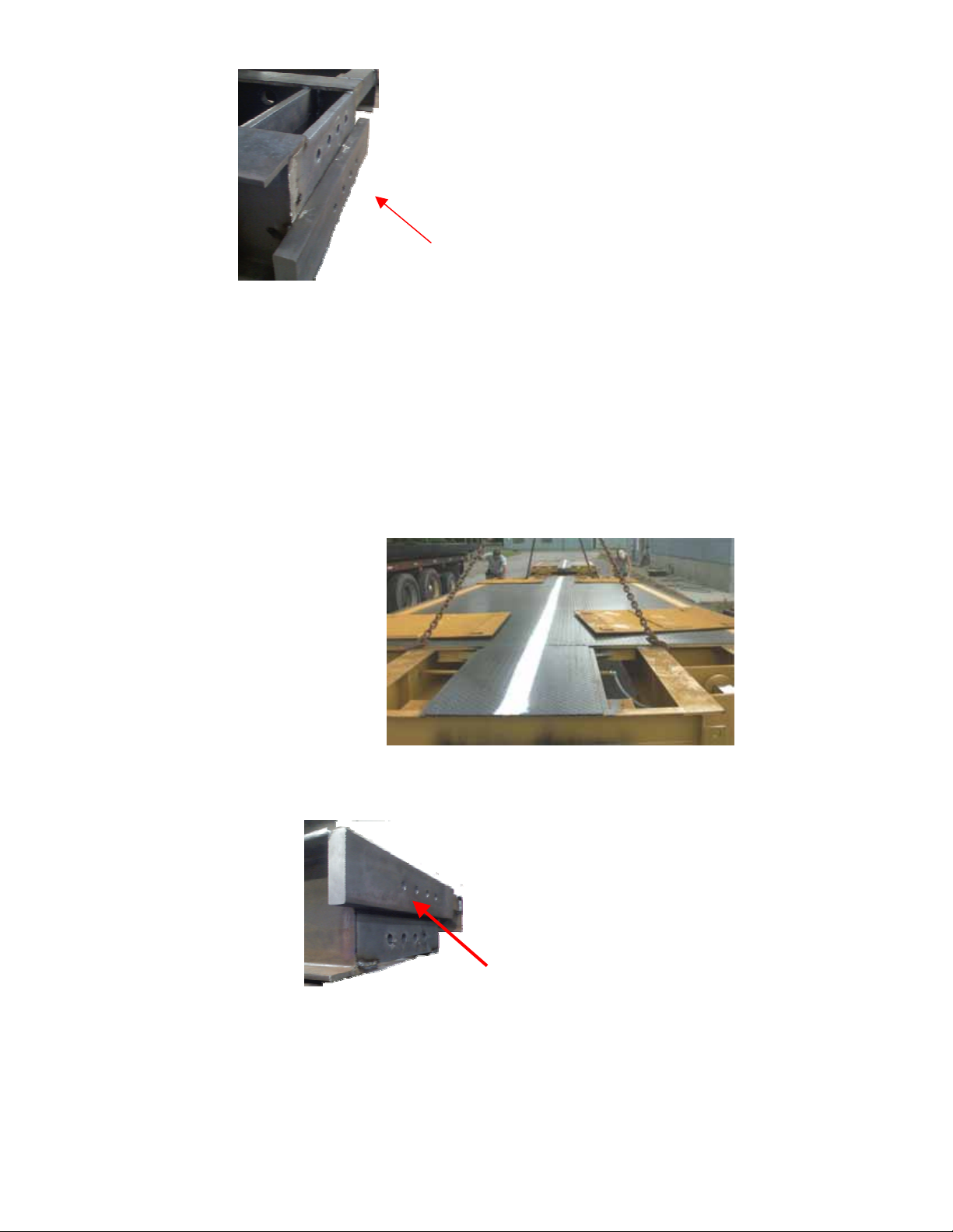
Lower Splice Plate
C. Place end module in place first. The section will have bumper bolts on
one end and lower splice plates on the other end. It is recommended that
blocking be placed under the main beam areas while setting the bridges.
The scale bridge should be approximately 1” from the end approach. The
bridges can be lifted by hooking a chain into the four corners of the
weighbridge for lifting of bridges. After bridge is set jack up each corner
and lower it onto the load cell mounts. Remove blocking. Using the crane
lift slightly on the bridge to remove the weight and shift bridge to align
with foundation if needed.
D. Install the second bridge into place. The center bridges will have an upper
splice plate on one end and a lower splice plate on the other end. (unless a
six load cell scale it will have bumper bolts on the other end)
Upper splice plate
F: Install splice bolts at the center sections. ¾” x 3 ½” bolts supplied
Page 4

G. Set side-to-side bumper blocks into place opposite corners of the scale.
H. If needed shift all stands to align the links. If you do not have equal pressure on
the cells you may need to shim under the stand. Recommend at least a 9” square plate. On
the concrete deck models adjust leveling bolts to match top of approach and to make sure
there is equal pressure on all cells.
I. Drill and set ¾” x 7” anchor bolts two per stand plus two for each of
the side to side bumper blocks.
J. Once everything has been leveled and shifted into place. Use a non-shrink grout
under each of the load cells stands. (Concrete deck models)
K. Adjust the Bumper bolts to minimum 1/8” and a max of ¼” on all four
corners of the scale Total of eight bumpers per scale.
Page 5

J. Wire the scale into the J-boxes as follows. Metal conduit runs along the outside
edge of the scale and from one side to the other. Flexible conduit to be cut and field
installed if desired from load cell conduit.
Page 6

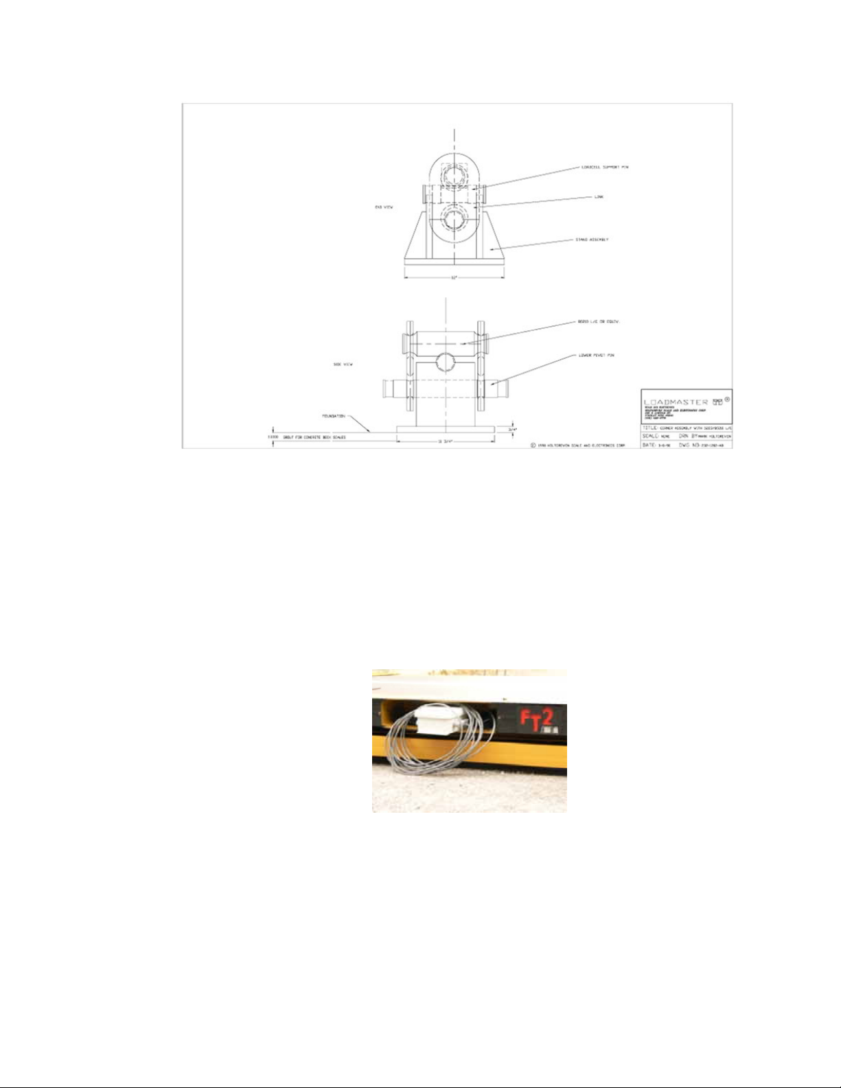
Section adjust wiring FT2 Truck scales
The scale will come with a section adjust box with a board similar to the one pictured below.
Main Cable Beldon Cable #8778
Coming from one of the scale modules.
Black/Green pair use Green for +EXC-1
Black/Yellow pair use Yellow for +EXC-2
Black /Blue pair use Blue for +EXC-3
Green/Black pair use Black for +EXC-4
Skip EXC-5
Yellow/Black pair use Black for –EXC
Black/White pair use White for +Sig
Black/Red pair use Red for -Sig
Cable to digital indicator see indicator wiring for color code.
+Exc to indictor +Exc or output
-Exc to indicator –Exc or output
+Sig to indicator +Sig or input
-Sig to indicator –Sig or input
Ground or Shield to Shield
Page 7

Summation box wiring FT2
The scale will have a fiberglass J-box mounted on one side of the scale.
Located near the center of the scale. (Center of one bridge on 3 section scale.)
Inside the box you will find a summation board similar to the picture below.
Section 1
Load Cell #1 Load cell #2
Section 2
Load Cell #3 Load Cell #4
Section 3
Load Cell #5 Load Cell #6
Section 4
Load Cell # 7 Load Celll #8
Section 5
Load Cell # 9 Load Cell #10
Optional side to side
Adjustment pots
(Install if needed)
Green/Black pair use Green for +EXC-1
Yellow/Black pair use Yellow for +EXC-2
Blue/Black pair use Blue for +EXC-3
Green/Black pair use Black for +EXC-4
Brown/Black pair us Brown for +EXC-5
Yellow/Black pair use Black for –EXC
Black/White pair use White for +Sig
Black/Red pair use Red for –Sig
Note: Use only the sections needed for example a 3 section scale only needs the first 3 sections
wired.
Individual Load Cell Wiring using the Artech 80210 or Equivalent cells.
Green Wire +Sig White Wire –Sig Black Wire –Exc Red Wire + Exc Shield Bare
Page 8

K. Install deck cover plates
L. Scale is now ready for calibration.
 Loading...