


Features
•
Operating voltage: 2.4~4.0V
•
On-chip SRAM
•
Robot function
•
Vibrato function
•
8kHz sampling rate
•
7-step level shifting
Applications
•
Toys
•
Mixers
•
Recorders
General Description
The HT8950 is a single chip CMOS LSI voice
modulator. It provides 7 steps to shift the frequency of an input voice, producing a dramati cal change in the outp ut.
The HT8950 provides two special effects: Vibrato and Robot. The Vibrato effect is generated
by alternating the freq ue ncy o f an i nput signa l
up and down at a rate of 8Hz. The Robot function, on the other hand, converts an input voice
into a Robot voice. B oth effects can be se lected
depending on which pin is triggered, either
ROB or VIB. For the output frequency level
shifting, the chip provides 7 steps which can be
selected from the two groups of pins namely,
HT8950
Voice Modulator
•
8-bit A/D and D/A converters
•
LED indicator with voice level
•
Push button selection or electronic mode
•
Few external components required
•
16-pin/18-pin DIP package
•
Audio system
•
Speech system
•
Telephone system
SW0, SW1 and SW2 for electronic direct selection and ROB, TGD, TGU and VIB for push
button selection.
The HT8950 includes a built-in microphone amplifier with an intern al bias, an 8-bit A /D converter, a built-in SRAM as well as a current
output type 8-bit D/A converter. The 8-bit A/D
and D/A converters with a sampling rate of
8kHz ensures a high quality and high S/N ratio
output voice. The chip provides an LED indicator which flashes with the vo lume of the input
voices. It is offered in a 16-pin or 18-pin DIP
package.
1 5th May ’98
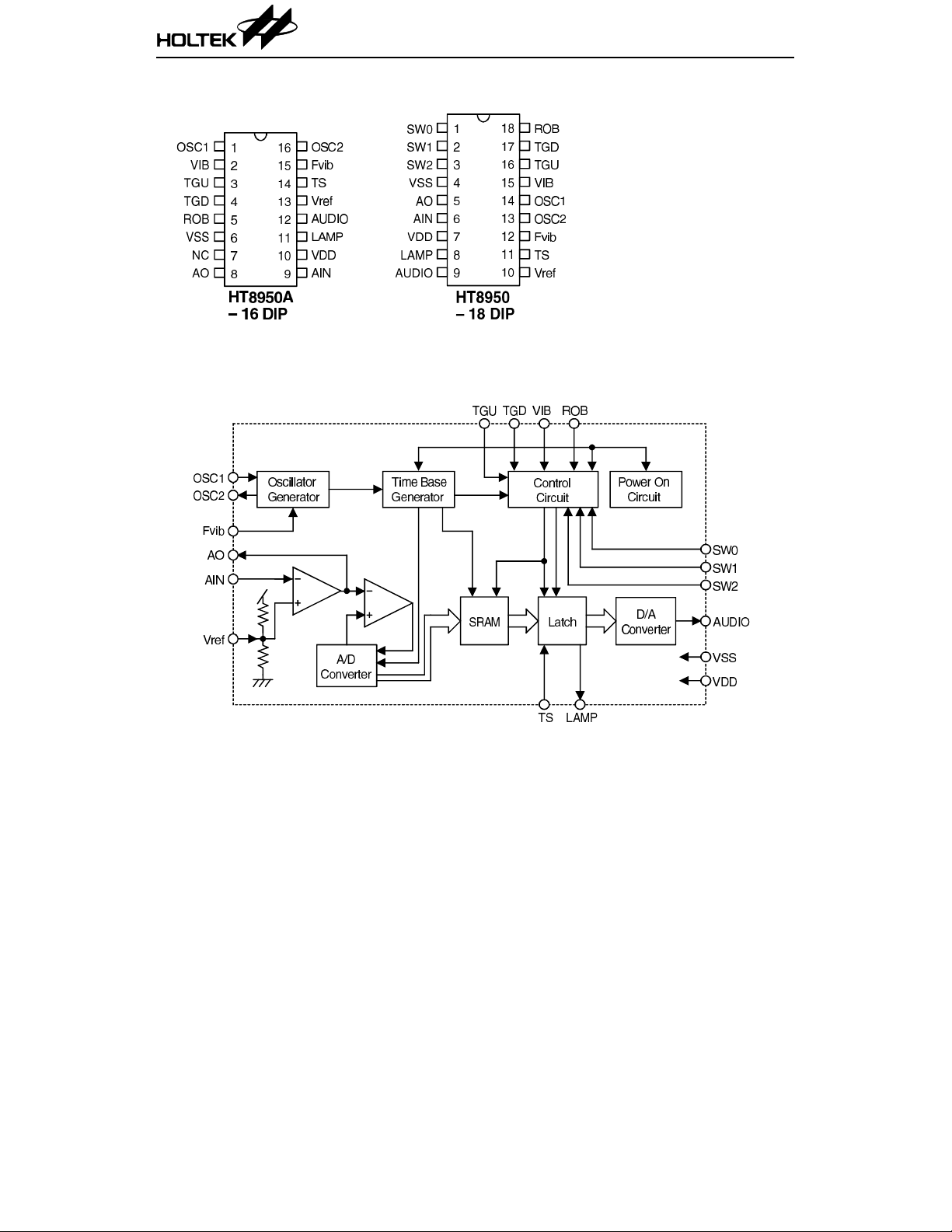
Pin Assignment
Block Diagram
HT8950
2 5th May ’98
HT8950
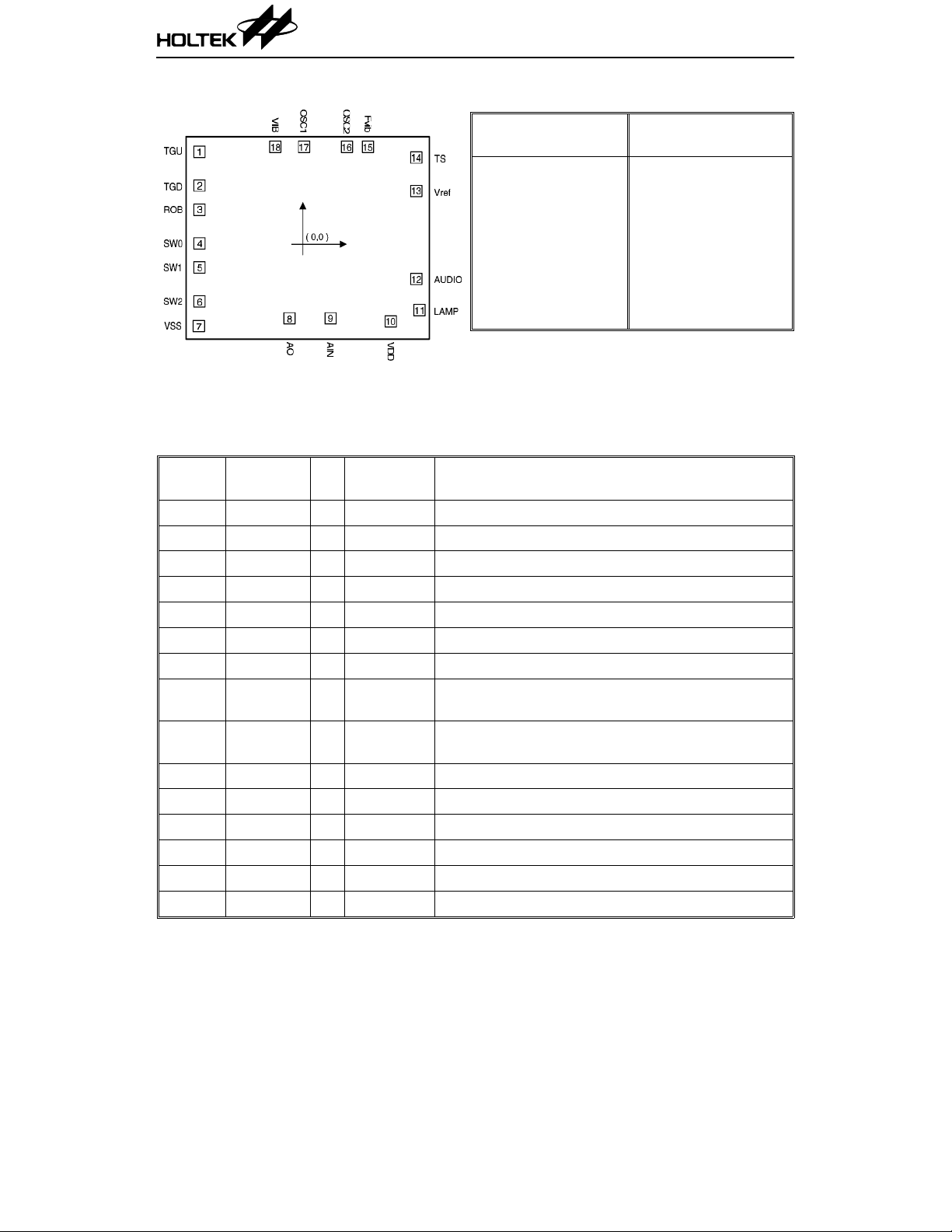
Pad Coordinates Unit: µm
Pad
No.
Chip size: 2350
∗ The IC substrate should be connected to VSS in the PCB layout artwork.
× 2080 (µm)
2
XY
1 –957.0 720.5 10 732.0 –774.0
2 –957.0 423.5 11 984.0 –675.0
3 –957.0 210.0 12 956.5 –400.0
4 –957.0 –87.0 13 956.5 374.5
5 –957.0 –299.5 14 956.5 671.5
6 –957.0 –596.5 15 530.5 765.5
7 –962.0 –815.0 16 345.50 765.5
8 –161.5 –747.5 17 –33.50 765.5
9 200.5 –747.5 18 –287.50 765.5
Pad
No.
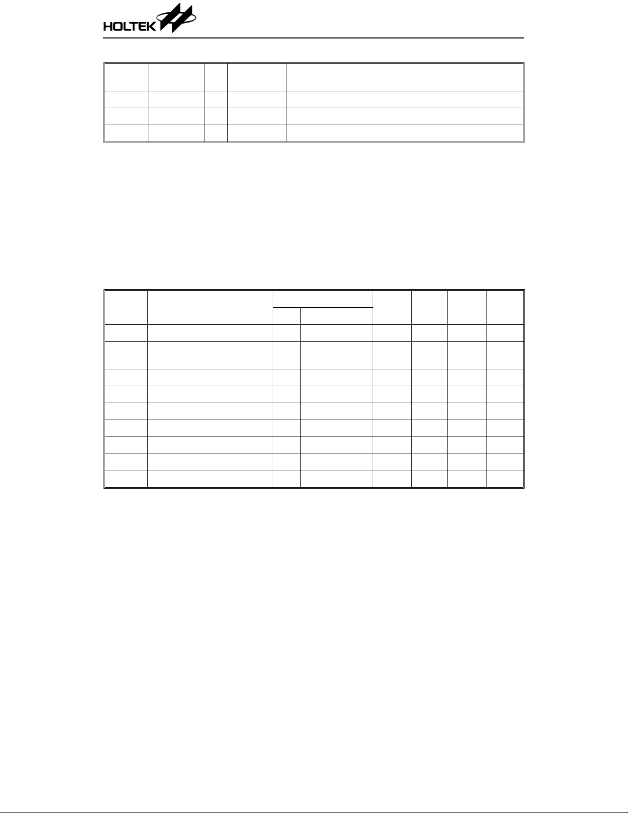
Pin Description (18 Pin Version)
Pin No. Pin Name I/O
1 SW0 I Pull-High Function setting pin (for electronic setting)
2 SW1 I Pull-High Function setting pin (for electronic setting)
3 SW2 I Pull-High Function setting pin (for electronic setting)
4 VSS I — Negative power supply (GND)
5 AO O — Internal amplifier output
6 AIN I — Internal amplifier input (inverted)
7 VDD O — Positive power supply
8LAMPO
9
10 Vref I — Internal amplifier reference voltage
11 TS I — For IC test only
12 Fvib O — Vibrato frequency control
13 OSC2 O — Oscillator output
14 OSC1 I — Oscillator input
15 VIB I Pull-High Switch to Vibrato mode (toggle)
AUDIO O
Internal
Connection
NMOS
Open Drain
PMOS
Open Drain
Description
Lamp output (brightness changes with voice volume)
Audio output
XY
3 5th May ’98
HT8950
Pin No. Pin Name I/O
Internal
Connection
Description
16 TGU I Pull-High Switch to Upward step mode
17 TGD I Pull-High Switch to Downward step mode (internal pull-high)
18 ROB I Pull-High Switch to Robot mode (internal pull-high)
Absolu te Maxim u m Rating s*
Supply Voltage.................................–0.3V to 6V Storage Temperature.................–50°C to 125°C
Input Voltage................. V
–0.3V to VDD+0.3V Operating Temperature...............–20°C to 70°C
SS
*Note: These are stress ra tings on ly. Stresses exceeding th e range spe cified und er “Absolute M axi-
mum Ratings” ma y cause substantial damage to the device. Functional operation of this
device at other conditions beyond those listed in the specification is not implied and prolonged
exposure to extreme condition s may affect device reliability.
Electrical Characteristics (Ta=25°C)
Symbol Parameter
V
I
OP
V
I
LAMP
A
I
O
V
V
f
OSC
Operating Voltage — — 2.4 3.0 4.0 V
DD
Operating Current 3V
Input Signal 3V — — — 580 mV
IN
Lamp Sink Current 3V VOL=1.3V 5.0 9.5 — mA
OPA Gain Value 3V Open loop — 2000 —
V
Audio Output Voltage 3V During silence — –1.0 — mA
“H” Input Voltage — — 0.7V
IH
“L” Input Voltage — — — — 0.3V
IL
Oscillating Freque ncy 3V R
Test Conditions
V
DD
Conditions
No load,
f
=640kHz
OSC
=47kΩ — 512 — kHz
OSC
Min. Typ. Max. Unit
— 2.0 10 mA
——V
DD
V
DD
4 5th May ’98

Functional Description
The HT8950 is a single chip LSI designed for
voice modulation. It provides 7 steps to shift the
frequency of an input voice signal up and down.
The chip is also equipped with two special effects; Vibrato and Robot.
The HT8950 includes a built-in amplifier, 8-bit
A/D converter and curre nt output typ e of 8-bit
D/A converter in addition to a built-in SRAM.
The brightness of an LED indicator changes
with the volume of the input voice signal.
Power on initial
The HT8950 ente rs the Robot state right after
power is initially switched on.
Robot state
The system goes in to the Robot sta te after the
ROB pin is triggered or power is turne d on. In
this mode, an input voice can be converted into
a robot voice.
Vibrato
An output voice will be generated with a vibrato
effect when the VIB pin is triggered, regardless
of what state the system is in. The vibrato effect
is toggle activated. In other words, when a voice
output is playing with a vibrato effect, this effect can be eliminated by retriggering the VIB
pin. The rate of vibrato effect can be changed by
adjusting the resistance of the external resistor
between the OSC2 and Fvil pins.
Voice modulation
The HT89 50 provides an 8-bit A/D and a D/A
converters with a sampling rate of 8kHz, ensuring a voice outpu t of high quality and with a
high S/N ratio. The chip includes 7 steps to shift
HT8950
the frequency of an input signal. The voice
modulation is selected and dete rmined by the
SW0~SW2 inputs.
Input
Step Mode
SW2 SW1 SW0
111
1 1 0 UP3 2
1 0 1 UP2 8/5
1 0 0 UP1 4/3
011NORMAL 1
0 1 0 DN1 8/9
0 0 1 DN2 4/5
0 0 0 DN3 2/3
Notes: The TGU switch elevates by one step
mode, and the TGD switch, on the other hand,
falls one step mode step by step as shown:
•
The system changes to the Rob ot state after
the ROB pin is triggered, regardless of what
state the system is in.
•
A voice outp ut is acco mpa ni ed with a vi bra to
effect after the VIB pin i s triggered, regardless of what state the system is in.
LED indicator
The HT8950 provides a LAMP pin to drive an
external LED. T he brightness of LED change s
with the volume of the input voice signal.
Controlled by TGU
and TDG
Speed
Ratio
Notes
5 5th May ’98

Application Circuits
16-pin version with an LM386 powe r am p lifier and a 6V power supply
HT8950
6 5th May ’98

18-pin version with an LM386 powe r am p lifier and a 6V power supply
HT8950
7 5th May ’98

16-pi n versio n wi th a transistor ou tput stage and a 6V po w er supply
HT8950
8 5th May ’98

18-pi n versio n wi th a transistor ou tput stage and a 6V po w er supply
HT8950
9 5th May ’98

16-pin version with a TDA2822 powe r am p lifier and a 6V po wer supply
HT8950
10 5th May ’98

18-pin version with a TDA2822 powe r am p lifier and a 6V po wer supply
HT8950
11 5th May ’98
 Loading...