

Win98 Keyboard Encoder
Features
Designed for Windows 95/98/NT
·
Supports 3 Windows 95 Keys
·
Supports Power, Sleep and Wake-up Win
·
dows 98 ACPI functions
Supports Japanese, Korean and Portuguese
·
Supports Japanese DOS/V 106-key
·
keyboard
Supports code set 1, for PS/2 model
·
30 keyboard
General Description
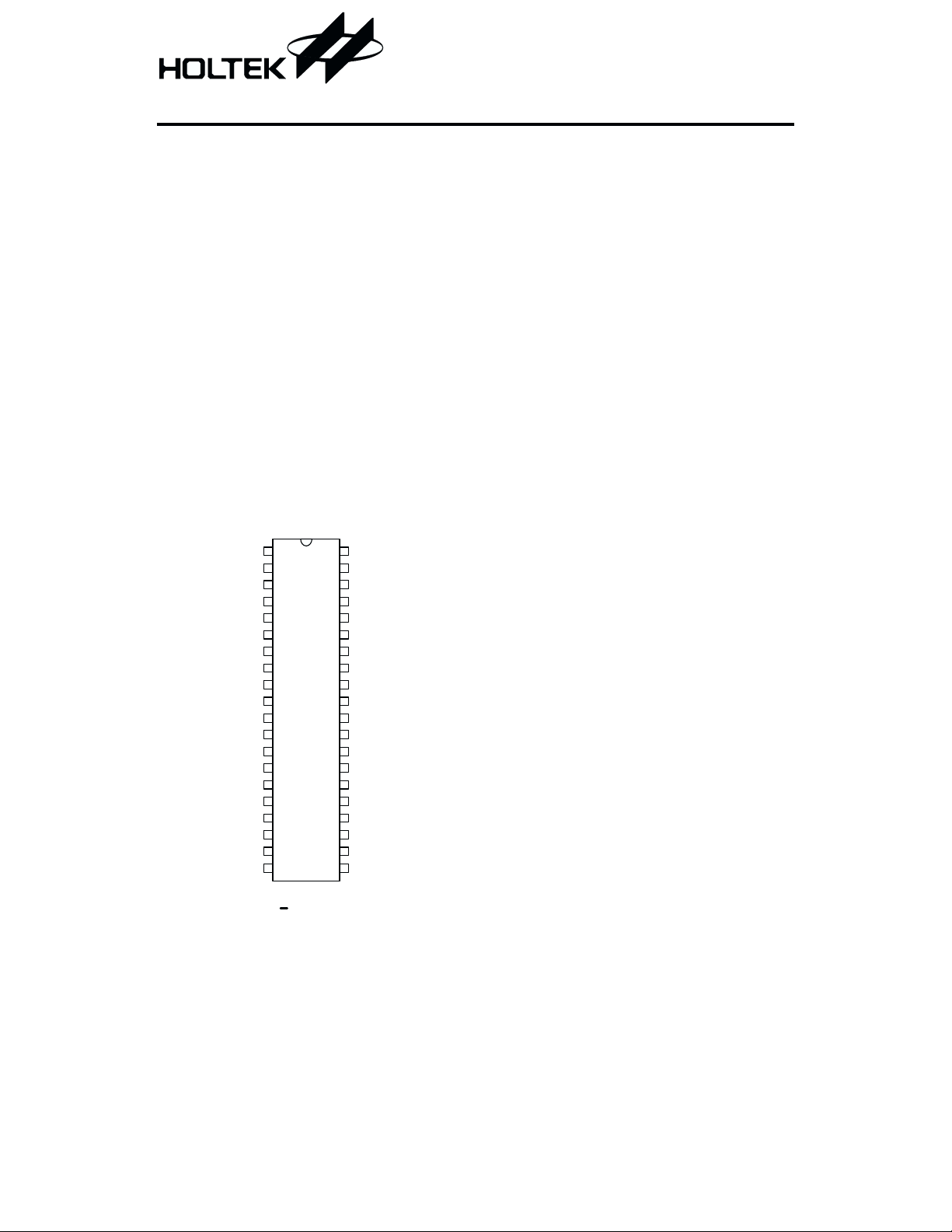
The HT82K28A is a keyboard encoder espe
cially designed for IBM PC/AT, IBM PS/2 and
all compatible machines.
The HT82K28A accepts keyboard inputs and
contains a 16-character first-in-first-out buffer
Pin Assignment
HT82K28A
Supports code set 2, for PC/AT, PS/2 model
·
50,60 keyboards
Supports code set 3, for PS/2 model
·
80 keyboard
RC oscillator
·
Phantom key detection
·
Minimal external components
·
Pin-compatible with Holtek HT6547E-2
·
40-pin DIP/DICE form
·
in which data is stored. An inexpensive RC os
-
cillator can be used for the system clock. The
device offers the advantage of simple imple
mentation in high performance and low cost
keyboard applications.
-
-
OSC1
VSS
VDD
VSS
IO 0
IO 1
C2
C3
C4
C5
C6
C7
R10
R11
R12
R0
R1
R2
R3
R4
1
2
3
4
5
6
7
8
9
10
11
12
13
14
15
16
17
18
19
20
40
39
38
37
36
35
34
33
32
31
30
29
28
27
26
25
24
23
22
21
H T82K 28A
4 0 D IP
C1
C0
DATA
CLOCK
R18
R17
NC
R16
CAP
NUM
SCRL
R9
R8
R15
R14
NC
R13
R7
R6
R5
1 February 16, 2000
HT82K28A
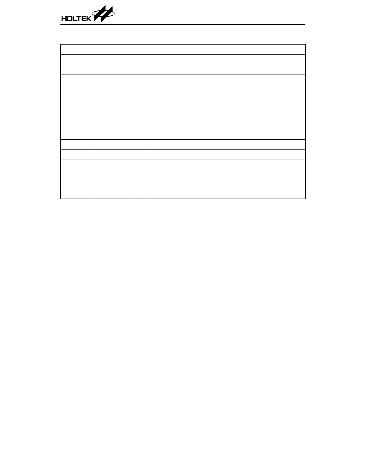
Pin Description
Pin No. Pin Name I/O Description
1 OSC1 I System clock input
2, 4 VSS
3 VDD
5, 6 IO0~IO1 O Customer defined optional output lines
39, 40,
7~12
16~23, 28,
29, 13~15
24, 26, 27
33, 35
25, 34 NC
30 SCRL O LED pin
31 NUM O LED pin
32 CAP O LED pin
37 CLOCK I/O Synchronous clock signal. Used to clock the transmission data
38 DATA I/O Bidirectional data transmission line
C0~C7 I Keyboard matrix scanning input pins
R0~R18 O Keyboard matrix scanning output pins
Negative power supply, ground
¾
Positive power supply
¾
No connection
¾
Absolute Maximum Ratings
Supply Voltage ............................4.75V to 5.25V
Storage Temperature.................-55°Cto125°C
Note: These are stress ratings only. Stresses exceeding the range specified under ²Absolute Maxi-
mum Ratings² may cause substantial damage to the device. Functional operation of this device
at other conditions beyond those listed in the specification is not implied and prolonged exposure to extreme conditions may affect device reliability.
Input Voltage .................V
Operating Temperature ..................0°Cto70°C
2 February 16, 2000
-0.3V to VDD+0.3V
SS
HT82K28A
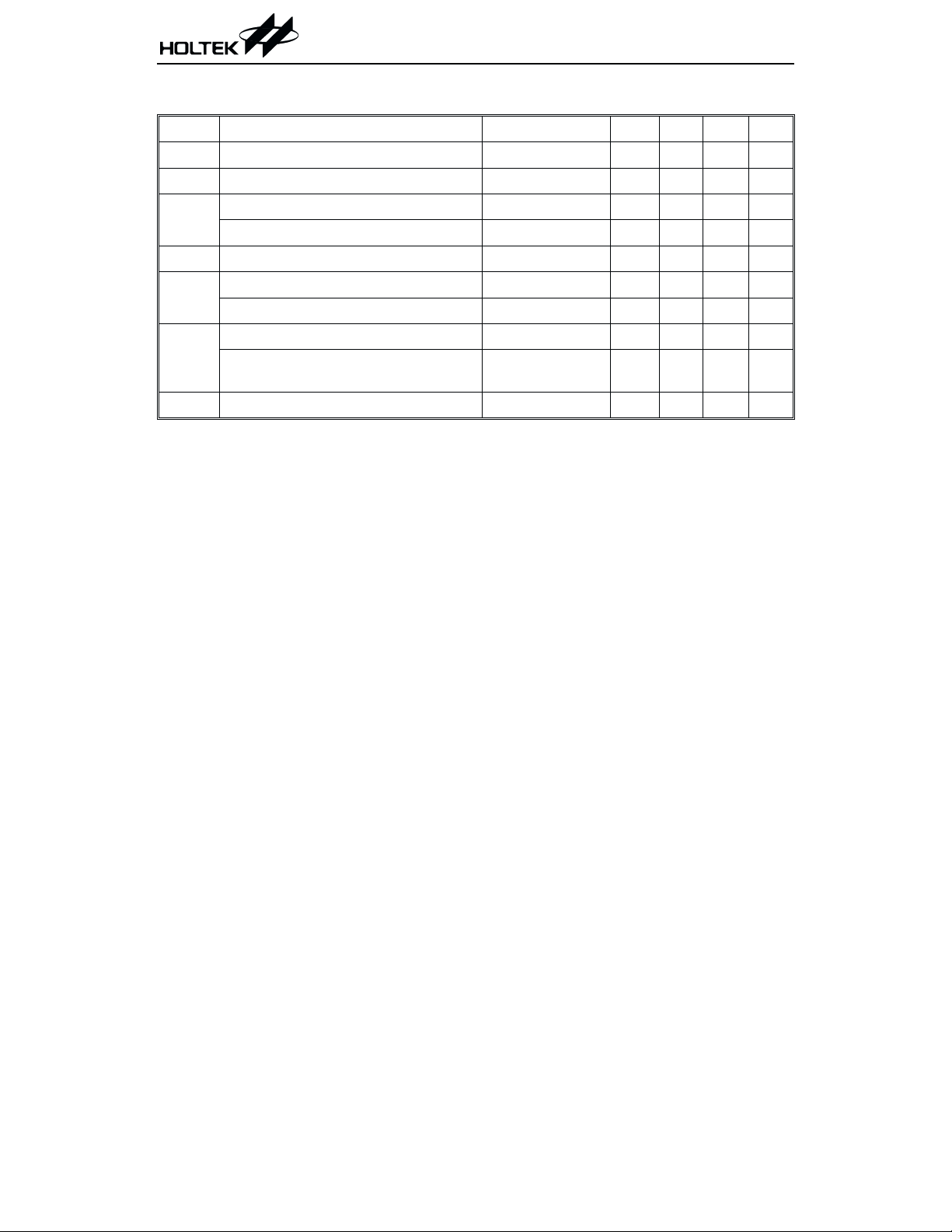
Electrical Characteristics
Ta=25°C
Symbol Parameter Test Conditions Min. Typ. Max. Unit
V
I
V
V
V
R
f
DD
DD
IL
IH
OL
ph
SYS
Operating Voltage
Operating Current
Input Low Voltage (C0~C7)
Input Low Voltage (DATA, CLOCK)
Input High Voltage
Output Low Voltage (R0~R18)
Output Low Voltage (DATA, CLOCK)
Internal Pull-high Resistance (C0~C7)
Internal Pull-high Resistance
(CLOCK, DATA)
System Clock
I
OL
I
OL
¾
4.75 5 5.25 V
¾¾
¾
¾
¾
=10mA
=15mA
¾
¾
0
0
3.5
¾¾
¾¾
51020
2515
¾¾4¾
25mA
0.6 V
¾
0.6 V
¾
V
¾
DD
0.5 V
0.5 V
kW
kW
MHz
V
3 February 16, 2000

Functional Description
The HT82K28A basic function is to detect key
press and release activity and to transmit the
corresponding scan code, as well as make and
break codes to the system.
The device also accepts commands from the sys
tem and responds to the system if necessary. All
communication between the keyboard and the
system is managed through the CLOCK and
DATA pins.
The keyboard begins to scan for pressed or re
leased keys and commands from the system after
the BAT (Basic Assurance Test) has been run.
Working modes
Three working modes are supported by the
HT82K28A. These are setup by the alternate
scan code command F0. The various modes are
described as follows.
Mode 3
·
Supports code set 3, for PS/2 model 80 key
boards.
·
-
Enters mode 3 when an F0 command is issued
followed by a 3".
·
Contains an 11 bit data stream, including one
start bit (always zero) eight data bits, one par
ity bit (odd parity) and one stop bit (always
one).
-
Buffers
The buffers support the following functions:
·
16-byte FIFO buffer: stores 16 keystrokes
scan codes.
·
Additional keystrokes will be ignored.
·
Response codes, i.e FA/FE... do not occupy
buffer positions.
HT82K28A
-
-
Mode 1
·
Supports code set 1 for PS/2 model 30 key
boards.
·
Enters mode1 after an F0 Command is issued
followed by a 1".
·
Contains an 11 bit data stream, including one
start bit (always zero) eight data bits, one parity bit (odd parity) and one stop bit (always
one).
·
All keys are typematic/make/break as default.
·
The working mode can be changed again in
this mode, by issuing an F0 command followed by an option. See the F0 command for
more detail.
Mode 2
·
Supports code set 2 for PC/AT, PS/2 model 50,
60 keyboards.
·
Enters mode 2 after power on.
The working mode can be changed by an F0
command followed by an option byte 1, 2 or 3.
See the F0 command for more details.
·
Contains an 11 bit data stream, including one
start bit (always zero) eight data bits, one par
ity bit (odd parity) and one stop bit (always
one)
·
All keys are typematic/make/break as default.
Basic assurance test - BAT
The following functions are offered by the Basic
-
Assurance Test:
·
Turns on LED status indicators.
·
Keyboard processor test.
·
RAM test.
·
Turns off LED status indicators, i.e. the
LEDs.
·
Reports the BAT result to the system.
Note: During the BAT, activity on the "clock"
and "data" line are ignored. The LED¢s
are turned on at the beginning and
turned off at the end of the BAT. The
BAT takes a minimum of 450ms after
POR and a maximum of 2.5s. The re
sponse to a satisfactory BAT completion
is ²AA² and response to BAT failure is
an ²FC² error. The reset keyboard com
mand ²FF² will also cause the keyboard
to execute the BAT. Completion codes
are sent between 300 and 500ms after a
-
reset command is acknowledged. After
the BAT, the keyboard sets the keys to
typematic and make/break, and sets the
default typematic rate and delay.
-
-
4 February 16, 2000
HT82K28A
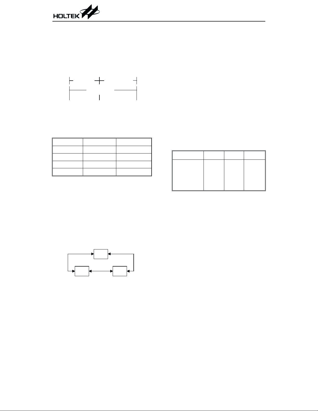
Power-on
Twoimportant activities take place when power
is first applied to the keyboard. The first is the
presence of an H/W signal POR (Power-On-Re
set) that resets the keyboard processor. The sec
ond activity is the running of the self test BAT
(Basic Assurance Test) routine.
PO R R eset
150m s~2s 300m s~500m s
450m s~2.5sec
Pow er on start BA T started BAT com plete
PC-type/mode/code set
The following table describes the relationship
between different computer types, the working
mode and the code sets.
PS/2 30 mode 1 code set 1
PC-AT mode 2 code set 2
PS/2 50 mode 2 code set 2
PS/2 60 mode 2 code set 2
PS/2 80 mode 3 code set 3
The mode can be changed between mode 2 & 3.
Keys
·
For code set 1, 2
All keys except the PAUSE key have a make
and break code. The PAUSE key has a make
code only.
The defaults except for PAUSE are make/
break/typematic. In mode 1, 2 and 3 the key
type may be changed to be one of the follow
ing:
m ode1
All keys except PAUSE are typematic.
Typematic means that the KB keeps send
-
ing make codes if the key is held down.
-
-
The data report is according to the
typematic rate/delay:
Default values are: delay 500ms ± 20%
10.9 char/sec ± 20%
The typematic rate and delay can be modi
-
fied with the F3 command.
¨
If two or more keys are held down, only the
last key pressed repeats at the typematic
rate.
Typematic operation stops when the last
key pressed is released even if other keys
are still held down.
If a key is pressed and held down while key
board transmission is inhibited, only the
first make code is stored in the buffer over
flow as a result of typematic action.
Four key types are supported as shown:
Key type press hold release
Typematic
Make/break
Make
Typematic/
make1
make1
make1
make1
make2
X
X
make2
X
break
X
break
make/break
Note: "make1" send out only one make
code.
"Make2" continue sending out make
codes until key is released.
"X" nothing sent out.
·
For code set 3
¨
-
Typematic
¨
Make/break
¨
Make
¨
Typematic/make/break
Can be configured by command
m ode2 m ode3
¨
Typematic
¨
Make/break
¨
Make
¨
Typematic/make/break
Time interval between phantoms
The time interval between two continuous error
codes 00/FF sent while phantom detected=
1000ms ± 20%
5 February 16, 2000
System command table
Command mode 1 mode 2 mode 3
FF - reset
FE - resend
FD - set key type make
FC - set key type make/break
FB - set key type typematic
FA - set all keys typematic/make/break
F9 - set all keys make
F8 - set all keys make/break
F7 - set all keys typematic
F6 - set default
F5 - default disabled
F4 - enable
F3 - set typematic rate/delay
F2 - Read ID
F1 F0 - select alternate scan codes
EF EE - Echo
ED - set/reset status indicators
HT82K28A
y
y
y
y
y
y
y
y
y
y
y
y
y
y
x
y
x
y
y
y
y
y
y
y
y
y
y
y
y
y
y
y
y
x
y
x
y
y
y
y
y
y
y
y
y
y
y
y
y
y
y
y
x
y
x
y
y
The keyboard should respond within 20ms, ex
cept when performing the BAT or executing a
reset command.
Command description
·
Default disable - F5
¨
Send an acknowledge FA to the system
¨
Clear its output buffer, FIFO
¨
Set the default key types
¨
Set typematic rate/delay as default value
¨
Clear the last typematic key
¨
Stop scanning and wait for further instruc
tion
·
Echo - EE
¨
Send an EE to the system
¨
Continue scanning if the keyboard is en
abled
Note: This command does not need to feed
back the ACK
·
-
Enable - F4
¨
Send an ACK to the system
¨
Clear output buffer
¨
Clear the last typematic key
¨
Start scanning
·
Invalid command
¨
Send an FE to the system
¨
No further activities
Note: No ACK
·
Read ID - F2
-
¨
Send an ACK to the system
¨
Discontinue scanning
¨
2 byte ID-AB, 83
The 2nd byte must follow the completion of
-
the first byte within 500ms
¨
Resume scanning
6 February 16, 2000

HT82K28A
·
Resend - FE
¨
Send the last code to the system
Note: * No FA response
·
Reset - FF
¨
Disable keyboard
¨
Send an ACK to the system, the keyboard
acknowledges the command with an ACK
and ensures the system accepts the ACK be
fore executing the command
¨
The system sets CLK=DATA=high for
500ms: acceptance of ACK
¨
The system can issue any command to the
KB within the 500ms period mentioned
above to override FF
¨
If no override, the system performs its BAT
and enters mode 2 (even if it is set to be
mode 3)
·
Select alternate scan code - F0
¨
Send an ACK to the system
¨
Clears both output buffer and the typematic
key
¨
Accept option byte
·
Set all keys - F7, F8, F9, FA
¨
FA: Set all keys to typematic/make/break
¨
F9: Set all keys to make
¨
F8: Set all keys to make/break
¨
F7: Set all keys to typematic
¨
Send an ACK to the system
¨
Clear output buffer
¨
Set all keys to the type indicated by the command
·
Set default - F6
¨
Send an ACK to the system
¨
Clear the output buffer
¨
Set to default key states: Default key type
typematic rate/delay
·
Set key type - FB,FC,FD
¨
FB : Set key type - Typematic
¨
FC : Set key type - Make/Break
¨
FD : Set key type - Make
¨
The keyboard responds with ACK, clears its
output buffer and prepares to receive key
identification
¨
Key identification is accomplished by the
system identifying each key by its scan code
value as defined in scan code set3.
¨
-
Only scan code set3 values are valid for key
identification
¨
The type of each identified key is set to the
value indicated by the command
¨
These commands can be sent using any
scan code set, but affect only the operation
of scan code set3
·
Set LED - ED
¨
Send ACK to the system
¨
Discontinue scanning
¨
Wait for the option from the system
¨
Respond with ACK to the system
¨
Set indicator
¨
If command comes from the system in place
of option, discard the set LED function and
then process the new command
¨
LED default after power on - all off
¨
Set default disable - do not change the LEDs
·
Set typematic rate/delay - F3
¨
Send an ACK to the system
¨
Stop scanning
¨
Wait for the system typematic rate and delay
¨
Send an ACK to the system
¨
Set rate/delay
¨
Bit 6,5 delay
¨
Bit 4,3,2,1,0 typematic rate
¨
Bit 7=0 (always)
Delay= (1+bit6,bit5) ´ 250ms
Typematic rate= 1/period
...where period= (8+A) ´ (2^B) ´ 0.00417
...where A= binary value of bit 2, 1 and 0
...where B= binary value of bit 4 and 3
7 February 16, 2000

b4~b0 Typematic
rate
00000
00001
00010
00011
00100
00101
00110
00111
01000
01001
01010
01011
01100
01101
01110
01111
·
Default
¨
delay: 500ms± 20%
¨
typematic rate=10.9 characters/sec± 20%
30.0
26.7
24.0
21.8
20.0
18.5
17.1
16.0
15.0
13.3
12.0
10.9
10.0
9.2
8.6
8.0
b4~b0 Typematic
rate
10000
10001
10010
10011
10100
10101
10110
10111
11000
11001
11010
11011
11100
11101
11110
11111
7.5
6.7
6.0
5.5
5.0
4.6
4.3
4.0
3.7
3.3
3.0
2.7
2.5
2.3
2.1
2.0
Commands to the system
00: keyboard detect a error/overrun (set 2, set 3)
AB,83: keyboard ID
AA: BAT completion
FC: BAT failure
EE: Echo
FA: Acknowledge
FE: Resend
FF: Keyboard detects a overrun (set 1)
·
FA: Acknowledge
If the KB (Keyboard) receives any valid input
except EE (echo) and resend (FE) then send
an FA to the system first.
If the command is EE, then send an EE back
to the system.
If the command is FE, then send the last key
code to system.
If there is an interrupt while sending FA, the
KB discards the FA and accepts the command
from the system and processes it.
·
00/FF: Key overrun
If the keyboard detects an overrun error, the
KB sends an overrun error code to the system.
mode 1: FF
mode 2,3: 00
HT82K28A
·
FE: Resend
The KB issues an FE when there is a parity
error in transmission.
Data communications
·
Data output
¨
If CLK=0, no transmission (keyboard inhib
ited).
¨
If CLK=1, DATA=0, no transmission (sys
tem request to send).
¨
If CLK=1, DATA=1, transmission permit
ted.
¨
Data will be valid before the trailing edge
and beyond the leading edge of the clock.
¨
The KB checks the clock line for an active
level at least every 60ms.
¨
If line contention occurs (system brings the
clock low before the tenth clock), set
clock=data=high.
·
Data input
¨
The system overrides the clock line for at
least 60ms
¨
The keyboard checks the state of the clock
line at intervals of no more than 10ms
¨
If a system request-to-send is detected, the
keyboard counts 11 data bits.
¨
Data will be valid before the rising edge and
beyond the falling edge
¨
After the 10th bit, the keyboard checks for
an active level on the "data" line. If the line
is active it is forced to be inactive, and
counts one more bit.
Note: This action signals the system that
the keyboard has received its data.
Upon reception of this signal, the
system returns to the ready state, in
which it can accept keyboard outputs
or goes to the inhibit state until it is
ready.
If the keyboard "data" line is found to be at an
inactive level following the 10th bit, a frame
error has occurred, and the keyboard contin
ues to count until the "data" line becomes ac
tive. The keyboard then makes the "data" line
inactive and sends a Resend.
-
-
-
-
-
8 February 16, 2000

Data stream
Mode 1,2,3
B1:
B2:
b3:
b4:
b5:
B6
b7:
b8:
b9:
b10:
b11:
Note: The parity bit is either 1 or 0, and the 8
data bits, plus the parity bit, always
have an odd number of 1 s.
start bit
always 0
data bit 0
data bit 1
data bit 2
data bit 3
data bit 4
data bit 5
data bit 6
data bit 7
parity bit
(odd par)
stop bit
always 1
HT82K28A
9 February 16, 2000

HT82K28A
Key code set 1
Key Number Make/Break Code Key Number Make/Break Code
30/B0
31/B1
32/B2
33/B3
34/B4
35/B5
73/F3
36/B6
1D/9D
38/B8
39/B9
E038/E0B8
E01D/E09D
45/C5
47/C7
4B/CB
4F/CF
48/C8
4C/CC
50/D0
52/D2
37/B7
49/C9
4D/CD
51/D1
53/D3
4A / CA
4E/CE
7E/FE
E01C/E09C
01/81
3B/BB
3C/BC
3D/BD
3E/BE
3F/BF
40/C0
41/C1
42/C2
43/C3
44/C4
57/D7
58/D8
46/C6
7B/FB
79/F9
70/F0
10
11
12
13
14
15
16
17
18
19
20
21
22
23
24
25
26
27
28
29
30
31
32
33
34
35
36
37
38
39
40
41
42
43
44
45
46
47
48
49
1
2
3
4
5
6
7
8
9
29/A9
02/82
03/83
04/84
05/85
06/86
07/87
08/88
09/89
0A / 8A
0B/8B
0C/8C
0D/8D
7D/FD
0E/8E
0F/8F
10/90
11/91
12/92
13/93
14/94
15/95
16/96
17/97
18/98
19/99
1A / 9A
1B/9B
2B/AB
3A / BA
1E/9E
1F/9F
20/A0
21/A1
22/A2
23/A3
24/A4
25/A5
26/A6
27/A7
28/A8
2B/AB
1C/9C
2A / AA
56/D6
2C/AC
2D/AD
2E/AE
2F/AF
50
51
52
53
54
55
56
57
58
60
61
62
64
90
91
92
93
96
97
98
99
100
101
102
103
104
105
106
107
108
110
112
113
114
115
116
117
118
119
120
121
122
123
125
131
132
133
10 February 16, 2000

Key code set 1
HT82K28A
Key Number
75
76
79
80
81
83
84
85
86
89
LWin
RWin
APP
When both shift keys are held down:
key number 75
Key Number Base +Left-Shift +Right-Shift
95
when both shift keys are held down:
key number 95
Base Case
Shift+Num
E0 52
/E0 D2
E0 53
/E0 D3
E0 4B
/E0 CB
E0 47
/E0 C7
E0 4F
/E0 CF
E0 48
/E0 C8
E0 50
/E0 D0
E0 49
/E0 C9
E0 51
/E0 D1
E0 4D
/E0 CD
E0 5B E0 AA E0 5B E0 B6 E0 5B E0 2A E0 5B
/E0 DB /E0 DB E0 2A /E0 DB E0 36 /E0 DB E0 AA
E0 5C E0 AA E0 5C E0 B6 E0 5C E0 2A E0 5C
/E0 DC /E0 DC E0 2A /E0 DC E0 36 /E0 DC E0 AA
E0 5D E0 AA E0 5D E0 B6 E0 5D E0 2A E0 5D
/E0 DD /E0 DD E0 2A /E0 DD E0 36 /E0 DD E0 AA
E0 35
/E0 B5
Left-Shift Right-Shift Num Lock
E0 AA E0 52
/E0 D2 E0 2A
E0 AA E0 53
/E0 D3 E0 2A
E0 AA E0 4B
/E0 CB E0 2A
E0 AA E0 47
/E0 C7 E0 2A
E0 AA E0 4F
/E0 CF E0 2A
E0 AA E0 48
/E0 C8 E0 2A
E0 AA E0 50
/E0 D0 E0 2A
E0 AA E0 49
/E0 C9 E0 2A
E0 AA E0 51
/E0 D1 E0 2A
E0 AA E0 4D
/E0 CD E0 2A
Both Shift
E0 AA E0 B6 E0 52/E0 D2 E0 2A E0 36
E0 AA E0 35
/E0 B5 E0 2A
Both Shift
E0 AA E0 B6 E0 35
/E0 B5 E0 2A E0 36
E0 B6 E0 52
/E0 D2 E0 36
E0 B6 E0 53
/E0 D3 E0 36
E0 B6 E0 4B
/E0 CB E0 36
E0 B6 E0 47
/E0 C7 E0 36
E0 B6 E0 4F
/E0 CF E0 36
E0 B6 E0 48
/E0 C8 E0 36
E0 B6 E0 50
/E0 D0 E0 36
E0 B6 E0 49
/E0 C9 E0 36
E0 B6 E0 51
/E0 D1 E0 36
E0 B6 E0 4D
/E0 CD E0 36
E0 B6 E0 35
/E0 B5 E0 36
E0 2A E0 52
/E0 D2 E0 AA
E0 2A E0 53
/E0 D3 E0 AA
E0 2A E0 4B
/E0 CB E0 AA
E0 2A E0 47
/E0 C7 E0 AA
E0 2A E0 4F
E0 CF E0 AA
E0 2A E0 48
E0 C8 E0 AA
E0 2A E0 50
/E0 D0 E0 AA
E0 2A E0 49
/E0 C9 E0 AA
E0 2A E0 51
E0 D1 E0 AA
E0 2A E0 4D
E0 CD E0 AA
Key Number Base +Left-Shift +Right-Shift
124
Key Number Base +Ctrl
126 E1 1D 45 E1 9D C5 E0 46 E0 C6
This key is not typematic, all associated scan codes occur on the make code.
ACPI Key Make Break Windows Virtual Key
Power E0 5E E0 DE N/A
Sleep E0 5F E0 DF N/A
Wake E0 63 E0 E3 N/A
E0 2A E0 37
/E0 B7 E0 AA
11 February 16, 2000
E0 37
/E0 B7
54/D4

HT82K28A
Key code set 2
Key Number Make/Break Code Key Number Make/Break Code
32/F032
31/F031
3A/F03A
41/F041
49/F049
4A/F04A
51/F051
59/F059
14/F014
11/F011
29/F029
E011/E0F011
E014/E0F014
77/F077
6C/F06C
6B/F06B
69/F069
75/F075
73/F073
72/F072
70/F070
7C/F07C
7D/F07D
74/F074
7A/F07A
71/F071
7B/F07B
79/F079
6D/F06D
E05A/E0F05A
76/F076
05/F005
06/F006
04/F004
0C/F00C
03/F003
0B/F00B
83/F083
0A/F00A
01/F001
09/F009
78/F078
07/F007
7E/F07E
67/F067
64/F064
13/F013
10
11
12
13
14
15
16
17
18
19
20
21
22
23
24
25
26
27
28
29
30
31
32
33
34
35
36
37
38
39
40
41
42
43
44
45
46
47
48
49
1
2
3
4
5
6
7
8
9
0E/F00E
16/F016
1E/F01E
26/F026
25/F025
2E/F02E
36/F036
3D/F03D
3E/F03E
46/F046
45/F045
4E/F04E
55/F055
6A/F06A
66/F066
0D/F00D
15/F015
1D/F01D
24/F024
2D/F02D
2C/F02C
35/F035
3C/F03C
43/F043
44/F044
4D/F04D
54/F054
5B/F05B
5D/F05D
58/F058
1C/F01C
1B/F01B
23/F023
2B/F02B
34/F034
33/F033
3B/F03B
42/F042
4B/F04B
4C/F04C
52/F052
5D/F05D
5A/F05A
12/F012
61/F061
1A/F01A
22/F022
21/F021
2A/F02A
50
51
52
53
54
55
56
57
58
60
61
62
64
90
91
92
93
96
97
98
99
100
101
102
103
104
105
106
107
108
110
112
113
114
115
116
117
118
119
120
121
122
123
125
131
132
133
12 February 16, 2000

Key code set 2
HT82K28A
Key Number
75
76
79
80
81
83
84
85
86
89
LWin
RWin
APP
When both shift keys are held down:
key number 75
Key Number Base +Left-Shift +Right-Shift
95
When both shift keys are held down:
key number 95
Base Case
Shift+Num
E0 70
/E0 F0 72
E0 71
/E0 F0 71
E0 6B
/E0 F0 6B
E0 6C
/E0 F0 6C
E0 69
/E0 F0 69
E0 75
/E0 F0 75
E0 72
/E0 F0 72
E0 7D
/E0 F0 7D
E0 7A
/E0 F0 7A
E0 74
/E0 F0 74
E0 1F E0 F0 12 1F E0 F0 59 E0 1F E0 12 E0 1F
/E0 F0 1F /E0 F0 1F E0 12 /E0 F0 1F E0 59 /E0 F0 1F E0 F0 12
E0 27 E0 F0 12 27 E0 F0 59 E0 27 E0 59 E0 27
/E0 F0 27 /E0 F0 27 E0 12 /E0 F0 27 E0 59 /E0 F0 27 E0 F0 12
E0 2F E0 F0 12 2F E0 F0 59 E0 2F E0 59 E0 2F
/E0 F0 2F /E0 F0 2F E0 12 /E0 F0 2F E0 59 /E0 F0 2F E0 F0 59
Left-Shift Right-Shift Num Lock
E0 F0 12 E0 70
/E0 F0 70 E0 12
E0 F0 12 E0 70
/E0 F0 71 E0 12
E0 F0 12 E0 70
/E0 F0 6B E0 12
E0 F0 12 E0 70
/E0 F0 6C E0 12
E0 F0 12 E0 70
/E0 F0 69 E0 12
E0 F0 12 E0 70
/E0 F0 75 E0 12
E0 F0 12 E0 70
/E0 F0 72 E0 12
E0 F0 12 E0 70
/E0 F0 7D E0 12
E0 F0 12 E0 70
/E0 F0 7A E0 12
E0 F0 12 E0 70
/E0 F0 74 E0 12
E0 4A
/E0 F0 4A
E0 F0 59 E0 70
/E0 F0 70 E0 59
E0 F0 59 E0 71
/E0 F0 71 E0 59
E0 F0 59 E0 6B
/E0 F0 6B E0 59
E0 F0 59 E0 6C
/E0 F0 6C E0 59
E0 F0 59 E0 69
/E0 F0 69 E0 59
E0 F0 59 E0 75
/E0 F0 75 E0 59
E0 F0 59 E0 72
/E0 F0 72 E0 59
E0 F0 59 E0 7D
/E0 F0 7D E0 59
E0 F0 59 E0 7A
/E0 F0 7A E0 59
E0 F0 59 E0 74
/E0 F0 74 E0 59
Both Shift
E0 F0 12 E0 F0 59 E0 70
/E0 F0 70 E0 12 E0 59
E0 F0 12 E0 4A
/E0 F0 4A E0 12
Both Shift
E0 F0 12 E0 F0 59 E0 4A
/E0 F0 4A E0 12 E0 59
/E0 F0 70 E0 F0 12
/E0 F0 71 E0 F0 12
/E0 F0 6B E0 F0 12
/E0 F0 6C E0 F0 12
/E0 F0 69 E0 F0 12
/E0 F0 75 E0 F0 12
/E0 F0 72 E0 F0 12
/E0 F0 7D E0 F0 12
/E0 F0 7A E0 F0 12
/E0 F0 74 E0 F0 12
E0 F0 59 E0 4A
/E0 F0 4A E0 59
E0 12 E0 70
E0 12 E0 71
E0 12 E0 6B
E0 12 E0 6C
E0 12 E0 69
E0 12 E0 75
E0 12 E0 72
E0 12 E0 7D
E0 12 E0 7A
E0 12 E0 74
Key Number Base +Shift / +Ctrl +Alt
124
Key Number Base +Ctrl
126 E1 14 77 E1 F0 14 F0 77 E0 7E E0 F0 7E
Note: this key is not typematic, all associated scan codes occur on the make of the key.
ACPI key Make Break Windows Virtual Key
Power E0 37 E0 F0 37 N/A
Sleep E0 3F E0 F0 3F N/A
Wake E0 5E E0 F0 5E N/A
E0 12 E0 7C
/E0 F0 7C E0 12
13 February 16, 2000
E0 7C
/E0 F0 7C
84/F084

Key code set 3
Key #
10
11
12
13
14
15
16
17
18
19
20
21
22
23
24
25
26
27
28
29
30
1
2
3
4
5
6
7
8
9
Break Code
0E/F00E
16/F016
1E/F01E
26/F026
25/F025
2E/F02E
36/F036
3D/F03D
3E/F03E
46/F046
45/F045
4E/F04E
55/F055
5D / F0 5D
66/F066
0D/F00D
15/F015
1D/F01D
24/F024
2D/F02D
2C/F02C
35/F035
3C/F03C
43/F043
44/F044
4D/F04D
54/F054
5B/F05B
5C/F05C
14/F014
Make/
Note
*
Default Key
State
Typematic
Typematic
Typematic
Typematic
Typematic
Typematic
Typematic
Typematic
Typematic
Typematic
Typematic
Typematic
Typematic
Typematic
Typematic
Typematic
Typematic
Typematic
Typematic
Typematic
Typematic
Typematic
Typematic
Typematic
Typematic
Typematic
Typematic
Typematic
Typematic
Make/Break
Key #
57
58
60
61
62
64
75
76
79
80
81
83
84
85
86
89
90
91
92
93
95
96
97
98
99
100
101
102
103
104
Make/
Break Code
59/F059
11/F011
19/F019
29/F029
39/F039
58/E058
67/F067
64/F064
61/F061
6E/F06E
65/F065
63/F063
60/F060
6F/F060
6D/F06D
6A/F06A
76/F076
6C/F06C
6B/F06B
69/F069
77/F077
75/F075
73/F073
72/F072
70/F070
7E/F07E
7D/F07D
74/F074
7A/F07A
71/F071
Note
*
*
*
*
*
*
*
*
*
*
*
*
*
*
*
*
HT82K28A
Default Key
State
Make/Break
Make/Break
Make/Break
Typematic
Make Only
Make Only
Make Only
Typematic
Typematic
Make Only
Make Only
Typematic
Typematic
Make Only
Make Only
Typematic
Make Only
Make Only
Make Only
Make Only
Make Only
Make Only
Make Only
Make Only
Make Only
Make Only
Make Only
Make Only
Make Only
Make Only
14 February 16, 2000

HT82K28A
Key #
31
32
33
34
35
36
37
38
39
40
41
42
43
44
45
46
47
48
49
50
51
52
53
54
55
56
Make/
Break Code
1C/F01C
1B/F01B
23/F023
2B/F02B
34/F034
33/F033
3B/F03B
42/F042
4B/F04B
4C/F04C
52/F052
5D/F05D
5A/F05A
12/F012
13/F013
1A/F01A
22/F022
21/F021
2A/F02A
32/F032
31/F031
3A/F03A
41/F041
49/F049
4A/F04A
51/ F0 51
Note
*
*
Default Key
State
Typematic
Typematic
Typematic
Typematic
Typematic
Typematic
Typematic
Typematic
Typematic
Typematic
Typematic
Typematic
Typematic
Make/Break
Typematic
Typematic
Typematic
Typematic
Typematic
Typematic
Typematic
Typematic
Typematic
Typematic
Typematic
Typematic
Key #
105
106
107
108
110
112
113
114
115
116
117
118
119
120
121
122
123
124
125
126
131
132
133
L Win
R Win
APP
Make/
Break Code
84/F084
7C/F07C
7B/ F0 7B
79/F079
08/F008
07/F007
0F/F00F
17/F017
1F/F01F
27/F027
2F/F02F
37/F0/37
3F/F03F
47/F047
4F/F04F
56/F056
5E/F05E
57/F057
5F/F05F
62/F062
85/F085
86/F086
87/F087
8B/F08B
8C/F08C
8D/F08D
Note
*
*
*
*
*
*
*
*
*
*
*
*
*
*
*
*
*
*
*
*
*
*
*
*
*
*
Default Key
State
Make Only
Typematic
Make Only
Make Only
Make Only
Make Only
Make Only
Make Only
Make Only
Make Only
Make Only
Make Only
Make Only
Make Only
Make Only
Make Only
Make Only
Make Only
Make Only
Make Only
Make Only
Make Only
Make Only
Make/Break
Make/Break
Make/Break
* Different from code set 2
15 February 16, 2000

Timing Diagrams
Data output
(1 ) (3 ) (3 )
CLK
D A T A S ta rt B it B it 0 P a rity B it S to p B it
T1 T2(2 )
1st
CLK
T3 T4
2nd
CLK
(3 )
(3 ) (4 )
10th
CLK
11th
CLK
T5
HT82K28A
(5 ) (7 )
(6 )
T1
T2
T3
T4
T5
Keyboard data input
(1 )
CLK
DATA Start Bit Bit 0 Parity Bit Stop Bit
T7
T8
T 9 T im e fro m in a c tiv e to a c tiv e C L K tra n s itio n , u s e d to tim e
Tim ing Param eter
D A TA transition to the falling edge of C LK
R ising edge of C LK to D ATA transition
D u ra tio n o f C L K in a c tiv e
D u ra tio n o f C L K a c tiv e
T im e to a u x ilia ry d e v ic e in h ib it a fte r c lo c k 1 1 to e n s u re
the auxiliary device does not start another transm ission
(4 )
(2 )
I/O
In h ib it
Tim ing Param eter
D u ra tio n o f C L K in a c tiv e
D u ra tio n o f C L K a c tiv e
w hen the auxiliary device sam ples D A TA
(3 )
1st
CLK
T7 T8
2nd
CLK
T9
(5 ) (7 )
9th
CLK
(5 )
10th
CLK
Min/Max
5/25 msec
5/T 4-5 msec
30/50 msec
30/50 msec
>0/50 msec
(6 )
Min/Max
30/50 msec
30/50 msec
5/25
11th
CLK
m
(8 )
sec
16 February 16, 2000
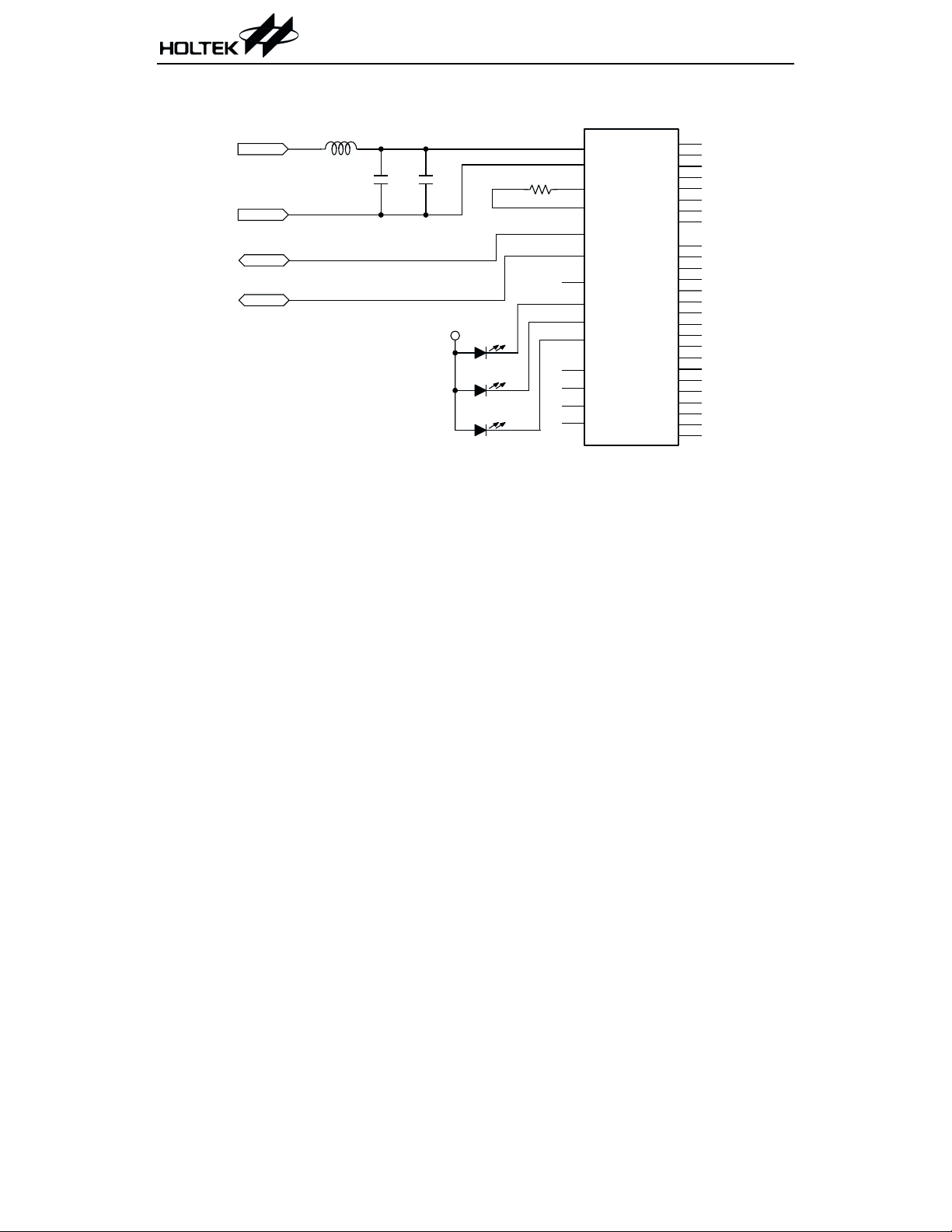
Application Circuits
HT82K28A
VDD
GND
DATA
CLOCK
F.B.
0.1mF
10mF
V
DD
L E D C A P
L E D N U M
L E D S C R L
3
VDD
4
1
2
38
37
5
32
31
30
25
34
36
6
VSS
OSC1
VSS
DATA
CLOCK
IO 0
CAP
NUM
SCRL
NC
NC
NC
IO 1
R
C7
C6
C5
C4
C3
C2
C1
C0
R17
R16
R15
R14
R13
R12
R11
R10
R9
R8
R7
R6
R5
R4
R3
R2
R1
R0
12
11
10
9
8
7
40
39
35
33
27
26
24
15
14
13
29
28
23
22
21
20
19
18
17
16
HT82K28A
17 February 16, 2000
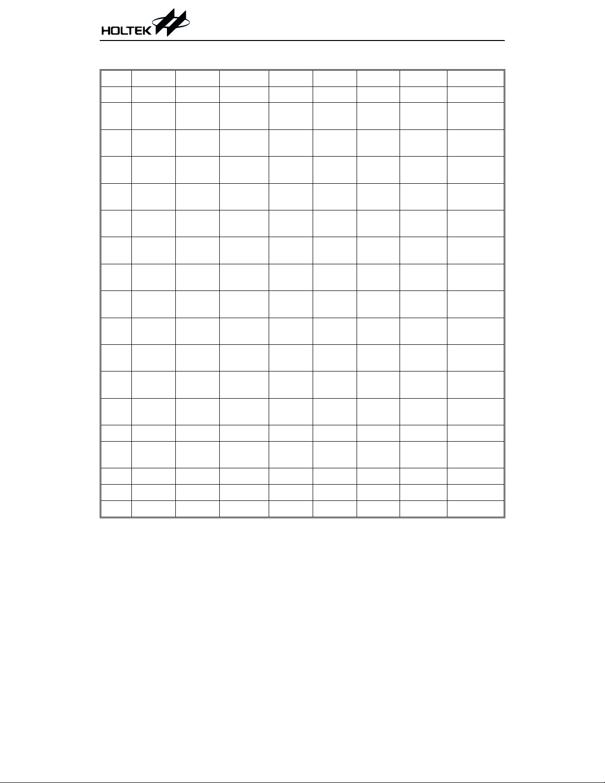
HT82K28A
Standard Holtek Win98 keyboard
C7 C6 C5 C4 C3 C2 C1 C0
R0 F5 L-CTRL WAKE-UP R-CTRL SLEEP POWER PAUSE
R1
R2
R3
R4
R5
R6
R7
R8
R9 PRINT R-ALT L-ALT
R10 F10 F9 F12 ENTER F11
R11 POWER DEL
R12 SLEEP INSERT
R13 PG DN PG UP NUM - NUM * NUM . NUM 3 NUM 6 NUM 9
R14 END HOME
R15 K94 R-SHF L-SHF WAKE UP
R16 K129 L-WIN K130
R17 K109 R-WIN
!
1
@
2
#
3
$
4
&
7
*
8
(
9
)
0
~
F1 K132 X K45 S
F2 K133 C F4 D F3 E
%
5
^
6
+
=
F8 APP
_
-
K131 Z ESC A TAB Q
CAP
LOCK
BVGFT R
NMHJY U
K56
?
/
DOWN
Arrow
RIGHT
Arrow
LEFT
Arrow
<
,
>
.
K42
NUM
LOCK
NUM / NUM 0 NUM 2 NUM 5 NUM 8
F6 K
LF7 O
"
'
SPACE NUM 1 NUM 4 NUM 7
UP
Arrow
:
;
|
\
NUM
ENTER
}
]
{
[
SCR
LOCK
BS K14
K107 NUM +
W
I
P
18 February 16, 2000

HT82K28A
The above key code is according to the Microsoft specification except for the following keys.
Key No Code Set 1 Make/Break Code Set 2 Make/Break Code Set 3 Make/Break
14 7D FD 6A F0 6A 5D F0 5D
94 7C FC 68 F0 68 68 F0 68
109 78 F8 63 F0 63 78 F0 78
129 F1 F1 F1
130 F0 F2 F2
19 February 16, 2000

HT82K28A
Holtek Semiconductor Inc. (Headquarters)
No.3 Creation Rd. II, Science-based Industrial Park, Hsinchu, Taiwan, R.O.C.
Tel: 886-3-563-1999
Fax: 886-3-563-1189
Holtek Semiconductor Inc. (Taipei Office)
5F, No.576, Sec.7 Chung Hsiao E. Rd., Taipei, Taiwan, R.O.C.
Tel: 886-2-2782-9635
Fax: 886-2-2782-9636
Fax: 886-2-2782-7128 (International sales hotline)
Holtek Semiconductor (Hong Kong) Ltd.
RM.711, Tower 2, Cheung Sha Wan Plaza, 833 Cheung Sha Wan Rd., Kowloon, Hong Kong
Tel: 852-2-745-8288
Fax: 852-2-742-8657
Copyright Ó 2000 by HOLTEK SEMICONDUCTOR INC.
The information appearing in this Data Sheet is believed to be accurate at the time of publication. However, Holtek
assumes noresponsibility arising from the use of the specifications described. The applications mentioned herein are
used solely for the purpose of illustration and Holtek makes no warranty or representation that such applications
will be suitable without further modification, nor recommends the use of its products for application that may pres
ent a risk to human life due to malfunction or otherwise. Holtek reserves the right to alter its products without prior
notification. For the most up-to-date information, please visit our web site at http://www.holtek.com.tw.
20 February 16, 2000
-
 Loading...