

Features
•
Single-chip CMOS construction
•
Measurement range: +3 2.0°C~+42.0°C
(+90.0~+108.0
Measurement accuracy:
Resolution: 0.1
•
Single 3.0V battery operation
•
Bonding option for Centigrade/Fahrenheit
measurement
°F)
±0.1°C (±0.2°F)
°C (0.1°F)
General Description
The HT7510 is a CMOS digital clinical thermometer IC for measuring body temperature in
Centigrade (
bonding option. The main function of HT7510 is
the same as HT7500. When interfaced with
°C) or Fahrenheit (°F) mode by its
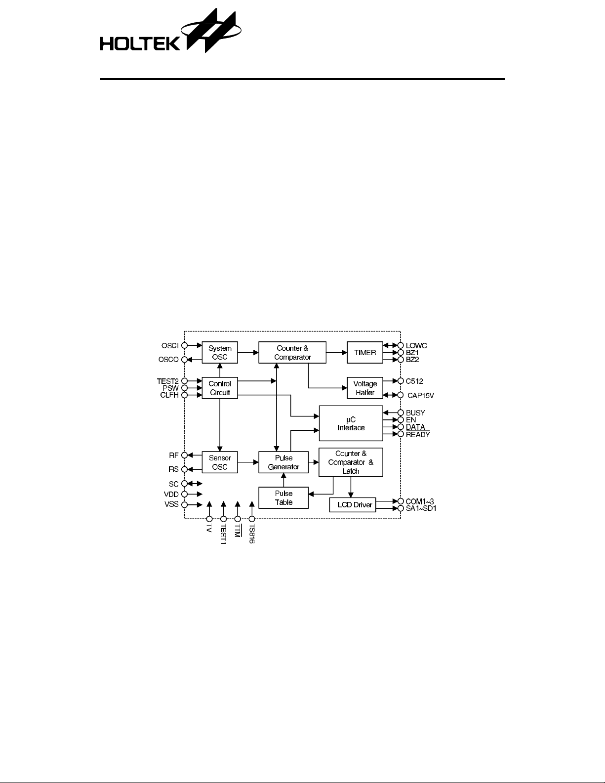
Block Diagram
HT7510
Clinic al Ther mom eter
•
Highest temperature hold
•
Auto power off after 8 min. 40 sec
•
One key input switch ON/OFF
•
Display the last measured temperature
•
Low voltage detection for 2.4V
•
Interface with HT84018-0D to provide voice
report function (Refer to HT84XXX data
sheet for detail specification)
HT84018-0D, HT7510 can provide voice report
function. It also provides alarm and auto power off
functions. The other electronic components are
LCD display, thermister, 3.0V battery, ON/OFF
switch, buzzer, resistors and capacitors.
1 10th Feb ’99
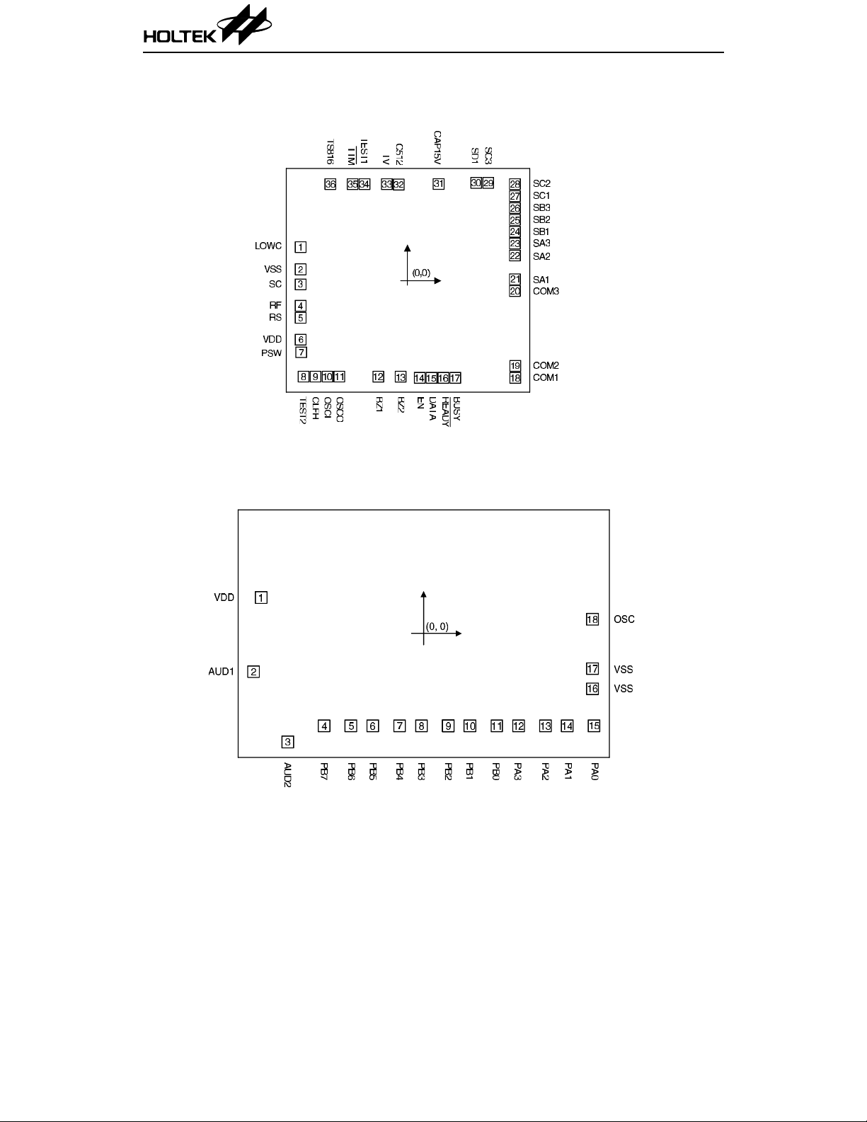
Pad Assignment
HT7510
HT7510
HT84018
Chip size: 132 × 121 (mil)
2
* The IC substrate should be connected to VDD in the PCB layout artwork.
Chip size: 2735 × 1835 (µm)
2
* The IC substrate should be connected to VSS in the PCB layout artwork.
2 10th Feb ’99

HT7510
Pad Coordinates
HT7510 Unit: mil
Pad No. X Y Pad No. X Y
1 –59.50 18.78 19 60.05 –47.43
2 –59.58 6.38 20 59.88 –5.74
3 –59.58 –2.00 21 59.88 0.89
4 –59.58 –13.98 22 59.88 14.07
5 –59.58 –20.61 23 59.88 20.70
6 –59.58 –32.81 24 59.88 27.33
7 –59.24 –39.87 25 59.88 33.96
8 –57.88 –53.42 26 59.88 40.59
9 –51.26 –53.42 27 59.88 47.22
10 –44.63 –53.42 28 59.88 53.85
11 –37.99 –53.42 29 44.9 7 54.61
12 –16.28 –53.47 30 38.33 54.61
13 –3.83 –53.47 31 17.38 53.97
14 6.80 –54.06 32 –4.89 53.63
15 13.43 –54.06 33 –11.52 53.85
16 20.06 –54.06 34 –23.93 53.85
17 26.69 –54.06 35 –30.56 53.85
18 60.05 –54.06 36 –42.97 53.85
HT84018
Pad No. X Y Pad No. X Y
1 –1125.31 249.74 10 320.15 –639.24
2 –1177.49 –263.79 11 505.75 –639.24
3 –939.68 –749.61 12 656.55 –639.24
4 –689.05 –639.24 13 842.15 –639.24
5 –503.45 –639.24 14 992.95 –639.24
6 –352.65 –639.24 15 1178.55 –639.24
7 –167.05 –639.24 16 1167.43 –382.18
8 –16.25 –639.24 17 1167.53 –242.08
9 169.35 –639.24 18 1167.53 99.04
3 10th Feb ’99
Unit: µm

HT7510
Pad Description
Pad No. Pad Name I/O Description
1 LOWC B For low voltage detector, open the pin when not in use.
2 VSS I Power supply GND
3 SC B Common point, NMOS open drain
4 RF O Connect reference resistor, PMOS open drain
5 RS O Connect sensor resistor, PMOS open drain
6 VDD I Power supply positive
7 PSW I Pull-low input pin, press switch to turn the power on or off
Pull-low test pin, for producti on, flo ating test , LCD disp lays
8TEST2 I
9 CLFH I
10 OSCI I For system oscillator in
11 OSCO O For system oscillator out
12 BZ1 O Buzzer output 1
13 BZ2 O Buzzer output 2
14 EN O Interface with HT84018-0D
15 DATA O Interface with HT84018-0D
16
17 BUSY I Interface with HT84018-0D
18~20 COM1~COM3 O LCD backplane drive, 3 level voltage out
21~23 SA1~SA3 O LCD segment drive
24~26 SB1~SB3 O LCD segment drive
27~29 SC1~SC3 O LCD segment drive
30 SD1 O LCD segment drive
31 CAP15V O 1.5V output for LCD display
32 C512 O Test pin for IC (512Hz output)
33 TV B T est pin for IC
34 TEST1 I Test pin for IC
35
36 TS816 I Test pin for IC
READY O Interface with HT84018-0D
TTM I Test pin for IC
the real time value , when connected to VDD, LCD disp lays
the highest value.
Connecting VSS for
°C, connect to VDD for °F
4 10th Feb ’99

HT7510
Absolute Maximum Ratings
Supply voltage............................... .... ....0V to 5V
Input voltage..................V
–0.5V to VDD+0.5V
SS
Note: These are stres s ratings only. Stresses exceeding the range specified under “Absolute Maxi-
mum Ratings” may cause substantial damage to the device. Functional operation of this device
at other conditions beyond those listed in the specification is not implied and prolonged
exposure to extreme condition s may affect device reliability.
Operation Temperature.............–20
Storage Temperature................–55
°C to +75°C
°Cto +125°C
Electrical Characteristics
Symbol Par ameter
V
I
I
f
R
R
DD
DD
STB
OSC
°C
°F
Operating Voltage — — 2.2 3.0 3.6 V
Operating Current 3V No load — 200 300
Standby Current 3V — — — 1.0
Oscillating Freque ncy 3V
Temperature Measurement
Accuracy at Range 35
Temperature Measurement
Accuracy at Range 95
°C~39°C
°F~102°F
Test Conditions
V
DD
Conditions
=1MΩ
R
OSC
min. Typ. Max. Unit
25.6 32 38.4
— — –0.1 — 0.1
— — –0.2 — 0.2
Ta=25°C
µA
µA
kHz
°C
°F
LCD Electrode Pattern
SA1 SA2 SA3 SB1 SB2 SB3 SC1 SC2 SC3 SD1
COM1F1A1B1F2A2B2F3A3B3A4
COM2E1G1C1E2G2C2E3G3C3B4
COM3 H1 D1 — — D2 H2 — D3 H3 C4
Note: 1/3 duty, 1/2 bias (LCD uses 3V)
Interface with HT84018-0D
5 10th Feb ’99

Functional Description
HT7510
The following description is for HT7510 only.
•
Power switch: press switch to turn the po wer
on or off.
•
When power is on: press the switch, then it will
generate a “beep” sound for 0.125 sec.
a. Displays all the segments first for 2 sec.
b. After a. shows the tempe rature of the last
reading for 2 sec.
c.
After b. shows L °C (or ° F ) for 0. 75 sec.
After c. displays the measurement tem-
d.
perature, the
speed of 1Hz.
e. If the temperature < 32
display shows L
If the tempera ture ≥ 42 °C (or 108 °F), the
f.
display shows H
g. The display always show the hi gher tem-
perature during the measurement.
h. If the measured temperature does not
change for more than 16 sec, the measurement is over an d the
stops.
When measurement is over, if the tempera-
i.
ture > 37.5
°C (or ° F) mark will flash at a
°C (or 90 °F), the
°C (or ° F) .
°C (or °F).
°C (or °F) mark flash
°C (or 99.5 °F),the buzzer alarms
j.
If the measurement is over 8 min. 40 sec.
the power will automatically turn off
When the measurement is over and the
k.
temperature rises within 8 min. 40 sec, the
°C (or °F) mark will flash again (repeat
from step 2-d), and s tarts to count again
until 8 min. 40 sec.
l.
When beep sound is on for 4 sec, the tem-
perature is not measured.
•
When power is off: the standby current ≤ 1µA.
•
The frequency of the buzzer is 5.3kHz
•
Bonding option: °C or °F.
•
Measurement to 0.1 degree in either °C or °F.
•
Sensor use 503ET.
•
Reference resistor value (sensor in 37.0 °C)
•
When battery voltage is low, the battery mark
“
∇” flashes at a sp eed of 1 H z and the m eas-
urement may not be accurate. The low voltage
detect: 2.4V
•
During the pro ces s o f ma ss prod u ctio n, in order to adjust the reference resistance (RF), let
test 2 be floati ng, the measure d tempera ture
will be the actual temp erature of the measured environmen t. It can be up or down, not
always the higher one.
± 0.05V.
“Beep-Beep-Beep---Beep-Beep-Beep---” for
4 sec, as follows:
if the temperature
the buzzer alarms “Beep-Beep-Beep -Beep” for 4 sec, as follows:
≤ 37.5 °C (or 99.5 °F),
Selection table for clinical thermometer
Part No. Voice Language
HT84018-0D English
6 10th Feb ’99

Flow Chart (HT7510/HT84018-0D)
HT7510
7 10th Feb ’99

HT7510
Application Circuits
Notes: HT7510’s substrate connected to VDD and HT84018-0D’s substrate connected to VSS.
LOWC is connected to an external resisto r for adjusting the detector level of a low voltage
detector. Open the pin when not in use.
OSCI, OSCO are connected to an external resistor, and form an RC oscillator with a built-in
capacitor for SYSTEM clock (3 2kHz)
RS, RF, SC constitute an alternating RC oscillator, which allows one oscillator, namely RS or
RF, active at a time.
REF (reference resistor) is a resistor value equal to 503ET sensor in 37.0
RENSOR is a 503ET thermistor.
S3 (open=for
°F, short=for °C)
°C or 98.6°F
8 10th Feb ’99
 Loading...