

Features
•
Single-chip CMOS construction
•
Single 1.5V battery operation
•
Measurement range: +32.00°C~+43.00°C
Measurement accuracy:
Resolution: 0.01
•
Auto self-test
°C
±0.1°C
General Description
The HT7501 is a CMOS digital clinical thermometer IC for measuring body temperature
from 32.00
self-test, auto power off and last time measured
°C~43.00°C. It also provides alarm,
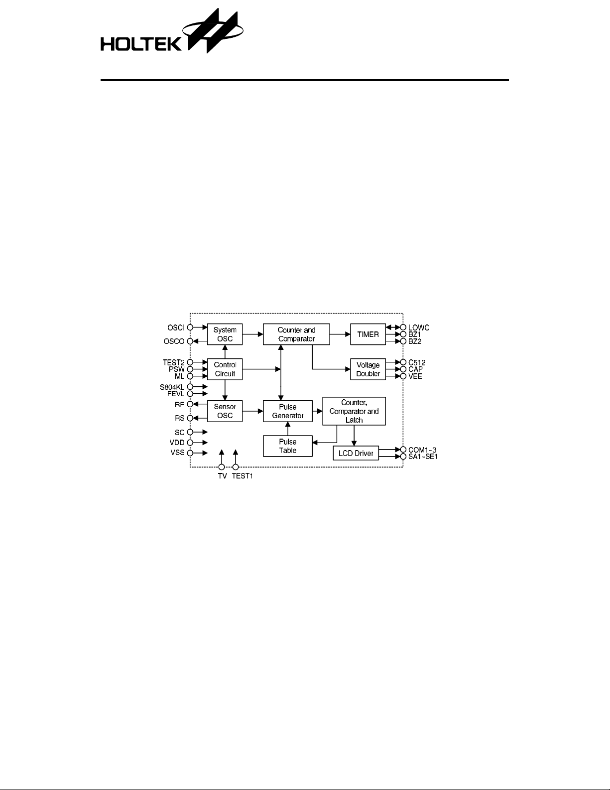
Block Diagram
HT7501
Clinic a l Thermom e ter
•
Alarm warning for fever
•
Highest temperature hold
•
Auto power off after 8 min 40 sec
•
One-key input switch for ON/OFF
•
Displays last time measured te mperatur e
temperature functions. The other electronic
components a re LCD displa y, thermister, 1.5V
battery, ON/OFF switch, buzzer, resistors and
capacitors.
1 8th Feb ’99
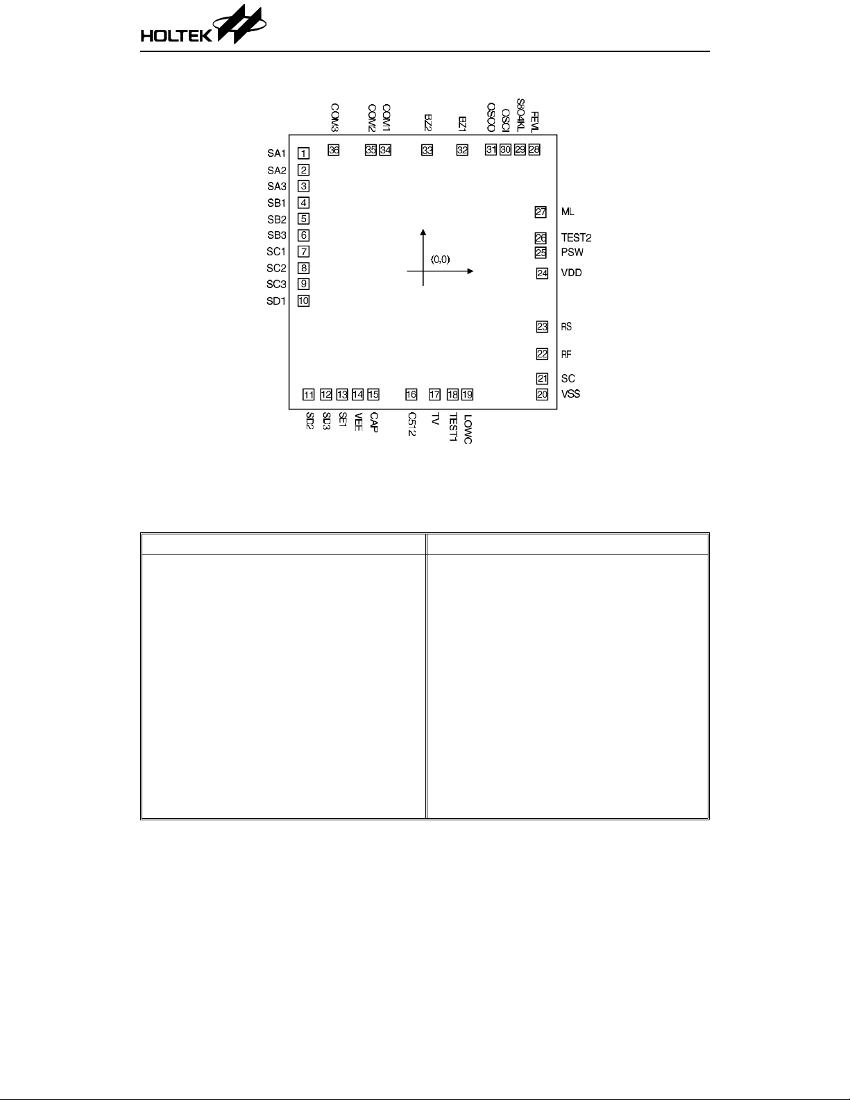
Pad Assignment
HT7501
Chip size: 121 × 124 (mil)
* The IC substrate should be connected to VDD in the PCB layout artwork.
2
Pad Coordinates Unit: mil
Pad No. X Y Pad No. X Y
1 –54.78 54.10 19 20.27 –56.53
2 –54.78 46.45 20 54.78 –56.53
3 –54.78 39.10 21 54.78 –49.30
4 –54.78 31.45 22 54.78 –37.99
5 –54.78 24.10 23 54.78 –25.58
6 –54.78 16.45 24 54.78 –1.02
7 –54.78 9.10 25 54.02 8.50
8 –54.78 1.45 26 54.02 15.13
9 –54.78 –5.91 27 54.02 27.11
10 –54.78 –13.56 28 51.13 55.85
11 –52.53 –56.53 29 44.50 55.85
12 –44.46 –56.53 30 37.87 55.85
13 –37.10 –56.53 31 31.24 55.85
14 –29.88 –56.53 32 18.02 56.61
15 –22.82 –56.53 33 1.95 56.61
16 –5.31 –56.53 34 –17.34 56.61
17 5.40 –56.53 35 –23.97 56.61
18 13.64 –56.53 36 –40.97 56.61
2 8th Feb ’99
HT7501
Pad Description
Pad No. Pad Name I/O Function
1~3 SA1~SA3 O LCD segment drive
4~6 SB1~SB3 O LCD segment drive
7~19 SC1~SC3 O LCD segment drive
10~12 SD1~SD3 O LCD segment drive
13 SE1 O LCD segment drive
14 VEE O Generate negative voltage (–1.5V)
15 CAP O For negative voltage, NMOS output
16 C512 O For negative voltage, inverter output
17 TV B Test pin for IC
18 TEST1 I Test pin for IC
19 LOWC B For the supply voltage detector. Open the pin when not in use.
20 VSS I Power supply GND
21 SC B Common point, NMOS open drain
22 RF O Connect reference resistor, PMOS open drain
23 RS O Connect sensor resistor, PMOS open drain
24 VDD I Positive power supply
25 PSW I Pull low input pin, push switch to turn the power on or off
Pull low test pin, for productio n test, floating LCD displays
26 TEST2 I
27 ML I Connect to VDD for memory function, otherwise floating.
28 FEVL I Floating with fever function, otherwise connect to VDD.
29 S804KL I Floating buzzer is 4kHz, connect to VDD if buzzer is 8kHz.
30 OSCI I For system oscillator in
31 OSCO O For system oscillator out
32 BZ1 O Buzzer output 1
33 BZ2 O Buzzer output 2
34~36 COM1~COM3 O LCD backplane drive, 3-level voltage out
the real time value , when connected to VDD, LCD disp lays
the highest value.
3 8th Feb ’99

HT7501
Absolu te Maximu m Ratings
Supply voltage................... .. .... .. .. .... .. .0V to 2.0V Input voltage...............VSS–0.5V to VDD+0.5V
Operation Temperature.............–20
Note: These are stress ratings only. Stresses exceeding the range spe cified under “Absolute Maxi-
mum Ratings” may cause substantial damage to the device. Functional operation of this device
at other conditions beyond those listed in the specification is not implied and prolonged
exposure to extreme condition s may affect device reliability.
Electrical Characteristics Ta=25°C
°C to +75°C Storage Temperature................–55°Cto +125°C
Symbol Parameter
V
I
DD
I
STB
f
OSC
R
DD
°C
Operating Voltage — — 1.3 1.5 1.65 V
Operating Current 1.5V No load — 60 100 µA
Standby Current 1.5V — — — 1.0 µA
Oscillating Freque ncy 1.5V R
Temperature Measurement
Accuracy at Range 35
°C~39°C
Test Conditions
V
DD
Conditions
=820kΩ 25.6 32 38.4 kHz
OSC
Min. Typ. Max. Unit
— — –0.1 — 0.1
°C
LCD Electrode Pattern
SA1 SA2 SA3 SB1 SB2 SB3 SC1 SC2 SC3 SD1 SD2 SD3 SE1
COM1F1A1B1F2A2B2F3A3B3F4A4B4A5
COM2E1G1C1E2G2C2E3G3C3E4G4C4B5
COM3H1D1 — —D2H2— D3 — I4 D4H4C5
Note: 1/3 duty, 1/2 bias (LCD uses 3V)
4 8th Feb ’99

Functional Description
HT7501
•
Power sw: push switch to turn the power on or
off.
•
When power on: push the switch, the n it will
generate a “beep” sound for 0.125 sec .
a. First display s all the segm ents on for 2 sec.
b. After a., as described above, then shows the
last-time measured temperature for 2.8 sec.
c. After b., shows the self-test temperature
(37.00
±0.01°C ) for 1 sec. The °C mark
will flash at a speed of 1Hz.
d. After c., displays the hig hest meas ured
temperature, then the
°C mark will flash at
a speed of 1Hz.
e. If the temperature is < 32.00
shows Lo
f. If the temperature is
shows Hi
°C.
≥ 43.00°C, the display
°C.
°C, the display
g. The display always shows the higher
temperature during the temperature
measurement.
h. If the measured temperature does not
change for more than 8 sec, the measure
ment is over and the
°C mark flash stops.
i. When measurement is over, if the
temperature > 37.50
°C the buzzer alarms
“beep-beep-beep---beep-beep-beep---” for 4 sec,
as follows:
j. It will automatically turn the power off
when measurement is over for 8 min 40 sec.
k. When measurement is over, but if the
temperature rises within 8 min 40 sec, the
°C mark will flash again ( repeat from
step 2-d), and starts to count 8 min 40 sec
again.
l. When beep sound is on for 4 sec, the
temperature is not measured.
•
When power off: the standby current ≤ 1µA.
•
The frequency of the buzzer is 4kHz or 8kHz
by pin option.
•
Fever alarm is pin option.
•
Measurement to 0.01 degree at °C.
•
Sensor use 503ET.
•
Reference res istor i s the value (senso r in 37 .00°C)
•
The low battery and “M” flag cannot display
when the temperature shows Hi or Lo.
•
When battery voltage is low, the battery mark
“
∇” flashes at a speed of 1Hz and the measure-
ment may not be accurate. The low voltage
detect: 1.35V
•
During the p roce ss o f m ass p ro ducti on , in or -
± 0.05V.
der to adjust the reference resistance (RF), let
test 2 be floatin g, the me asure d tempera ture
will be the actual tem perature of the measured environmen t. It can be up or down, not
always the higher one.
if the temperature
≤ 37.50°C, the buzzer
alarms “beep-beep-beep-beep-” for 4 sec, as
follows:
5 8th Feb ’99
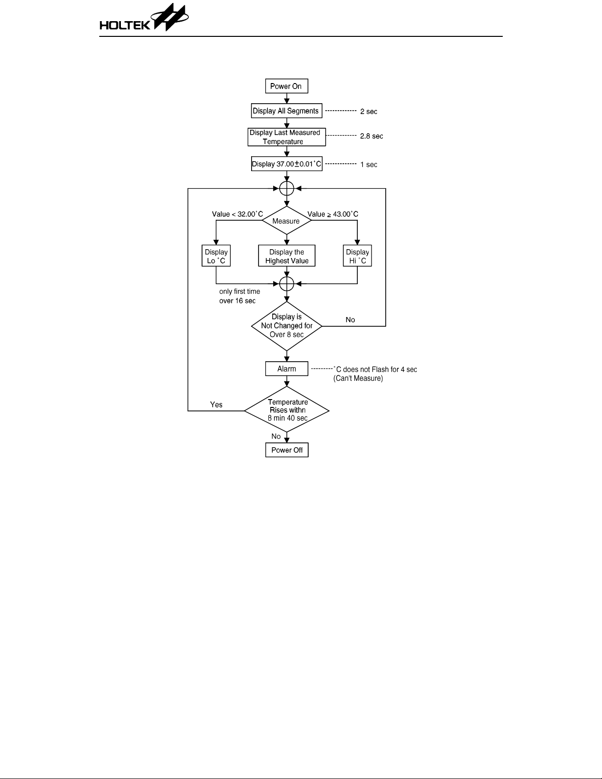
Flow Chart
HT7501
6 8th Feb ’99

Application Circuits
Notes: Substrate connect to VDD.
VEE, CAP and C512 are externally connected to capacitors for stabilizing VEE (=–1.5V).
BZ1 and BZ2 are connected to an external Buzzer for generating sounds.
LOWC is conne cted to an external re sistor for adjusti ng the detector le vel of a low voltage
detector. Open the pin when not in use.
OSCI, OSCO are con nected to an external resistor, and form an RC oscillator with a built-in
capacitor for SYSTEM clock (=32kHz)
RS, RF, SC constitute an alternating RC oscillator, which allows one oscillator, namely RS or
RF, active at a time.
REF (reference resistor) is a resistor value equal to 503ET sensor in 37 .00
SENSOR is a 503ET thermistor.
°C.
HT7501
7 8th Feb ’99
 Loading...