

Features
•
1/3 bias, 1/4 duty, 32 × 4 pattern,
3.0V LCD driver
•
Built-in sound generator which can
generate 11 kinds of sound effects
General Description
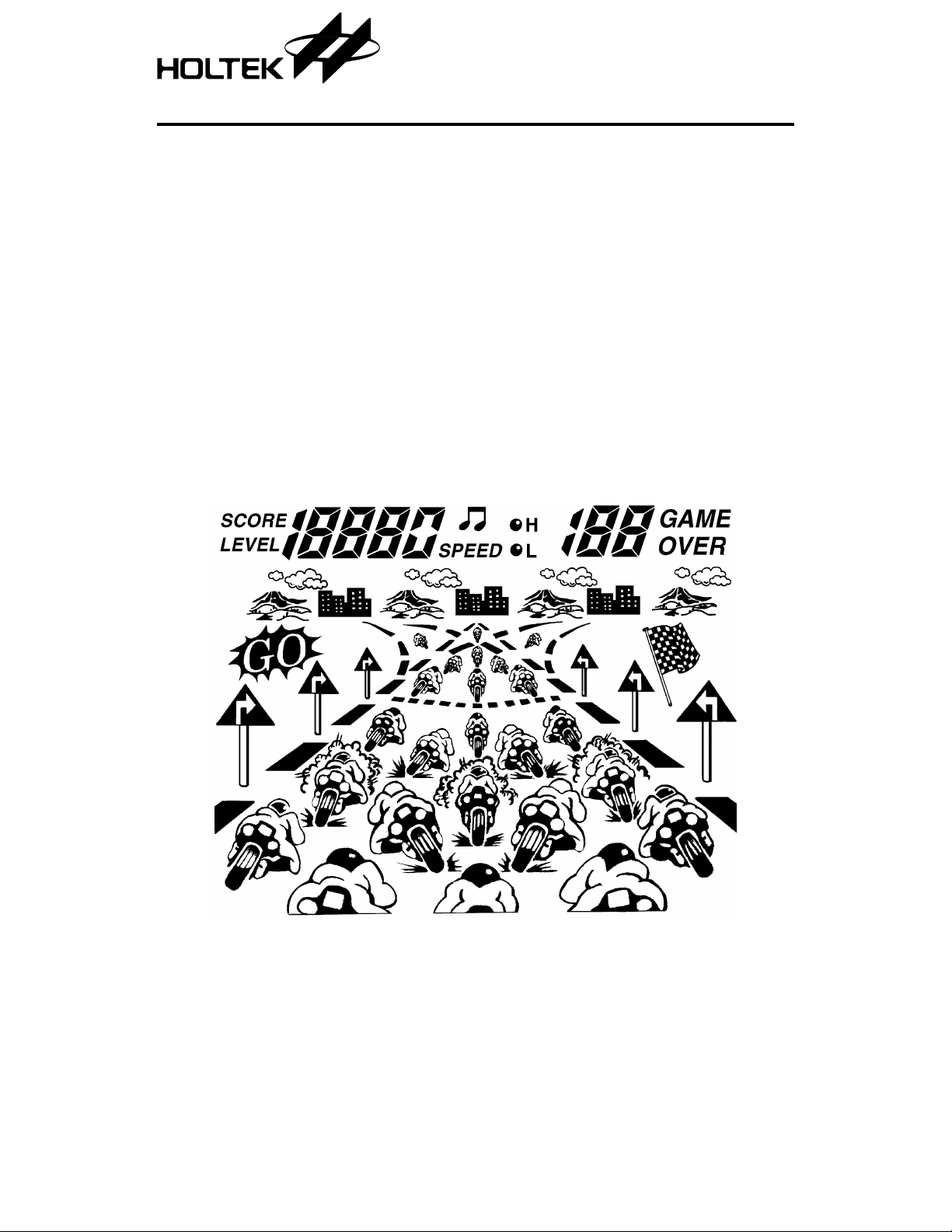
HT1137A is a motorcycle LCD game designed by
HOLTEK. The race can run over straight or
crooked roads, exercising the players skill in not
only trying to overtake other contestants but in
negotiating severe turns at high speed. The exci ting game is sensational and gripping. This game
consists of nine major stages and each major stage
contains three minor stages. Each minor stage is
different. The first minor stage is normal motor-
LCD Pattern
HT1137A
Motorcycle LCD G a m e
•
RC oscillator
•
Consists of nine major and three minor
stages
cycle racing, in which the player needs to avoid
and overtake the opponent’s motorcycle. In the
second minor stage, the opponent’s motorcycle
will change lane in different directions at different time. At the third stage, the motorcycle is on
a slippery surface. The player’s motorcycle will
slip to the left or to the right. The direction
needs to be controlled so that collisions with the
other motorcycles is avoided.
1 19th Nov ’98

Functional Description
HT1137A
Key description
•
START/ON
During power OFF state, pressing this key
turns on the power and starts the game. In the
power ON condition, pressing this key starts
a new game.
•
RESET
This key can be pressed at any time to reset
the game thus returning it to the starting
mode, and the highest score is cleared.
•
PAUSE
When the game is in progre ss, pressing this
key can temporarily stop the game. The
screen is frozen and all sound is muted. Press
it again, and the game continues. In the pause
condition, all keys are disabled except OFF,
START/ON, MUTE and PAUSE keys.
•
MUTE
This key switches the sound ON or OFF.
Sound is au tomatically on at reset or sta rt.
Press once to switch the sound off.
•
OFF
The power is switched off when this key is
pressed.
•
ACC
Relative to the current speed and present gear
setting, the motorcycle increases or maintains
its speed when the ACC or acceleration is
pressed.
•
BRAKE
Pressing this key can decrease the speed
quickly. If the ACC key and this key are
pressed at the same time, then the speed
gradually decreases.
•
Hi-Lo
In Lo gear , the hig hest speed is 150 kph. If, for
instance, you are riding at 100 kph and then
change to Hi, it’s possible to reach 300 kph.
However, if the speed drops below 100 kph
and you’re still in Hi gear, the speed will
gradually decrease to zero.
•
LEFT
Shifting to the left can balance the left bound
centrifugal force in a left turn so that the
motorcycle will not be thrown to the right side
of the road.
•
RIGHT
Shifting to the right can balance the right
bound centrifugal force in a right turn so that
the motorcycle will not be thrown to the left
side of the road.
•
RESET+ ACC+ BRAKE
Press all of these keys at the same time and
then release the RESE T key, all the patterns
will be shown.
Operational desc r i p tion
•
When START/ON is pressed, a prelude is
played and the highest reco rd and score are
shown. When “GO!” is displayed, the motorcycles are revved-up to start.
•
The time limit for each minor stage is 90
seconds. The higher the stage is, the more the
opponents appear on the road. Hence, the
player must avoid time wasting collisions and
reach the destination within the given time in
order to pass through to the next stage.
2 19th Nov ’98

HT1137A
•
When the speed is higher than 100, press the
Hi-Lo key to change the low gear to high gear
up to 300 kph. If the speed is lowe r than 1 00
kph in high gear, the speed will gradually
decrease to zero.
•
During the competition, the player mu st constantly press the ACC key to maintain or
increase the speed, otherwise the speed will
gradually decrease. In high gear the speed
will decrease to 150 kph; in low gear the speed
will decrease to 0. When the speed is lower
than 100 kph, the player should avoid a collision because the speed is slow that the othe r
opponents will catch up with him.
•
When turning to the left or to the right, press
the opposite direction key to balance the centripetal force. Otherwise, the centrifugal force
will throw the motorcycle off the road.
•
The first and second minor stage is a chasing
contest in the road. The differen ce is that in
the first stage the opponent cannot change
lane as he/she wishes. However, in the second
stage lanes can b e changed. It increas es the
difficulty and preference.
•
The third min or stage is a contest on a s lippery road. The player’s motorcycle will slip
around so that direction control is important.
•
When one of the following five situations occur, player’s motorcycle will be destroyed so
the game needs to be restarted.
♦
Hit the front motorcycle
♦
Player is hit by the opponent from the back
♦
Wrong direction so the motorcycle is off line
♦
Direction control is not good, so the motorcycle is thrown off line by centrifugal force
♦
Player’s motorcycle collided while shifting
•
At each minor stage, the number of collision is
not counted.
Counting method
•
Beating the opponent: every win over an o pponent, 10 points are scored.
•
Bonus score: when a minor s tage is over, the
number of seconds left multiplied by 10 is the
bonus score.
Sound effects
•
Brake sound
•
Low gear driving sound
•
High gear driving sound
•
Collision sound
•
Brushing past the opponent
•
Counting sound for start
•
Starting music (prelude)
•
Pass-through music
•
Game over music
•
Slip sound
•
Wrong gear sound
3 19th Nov ’98
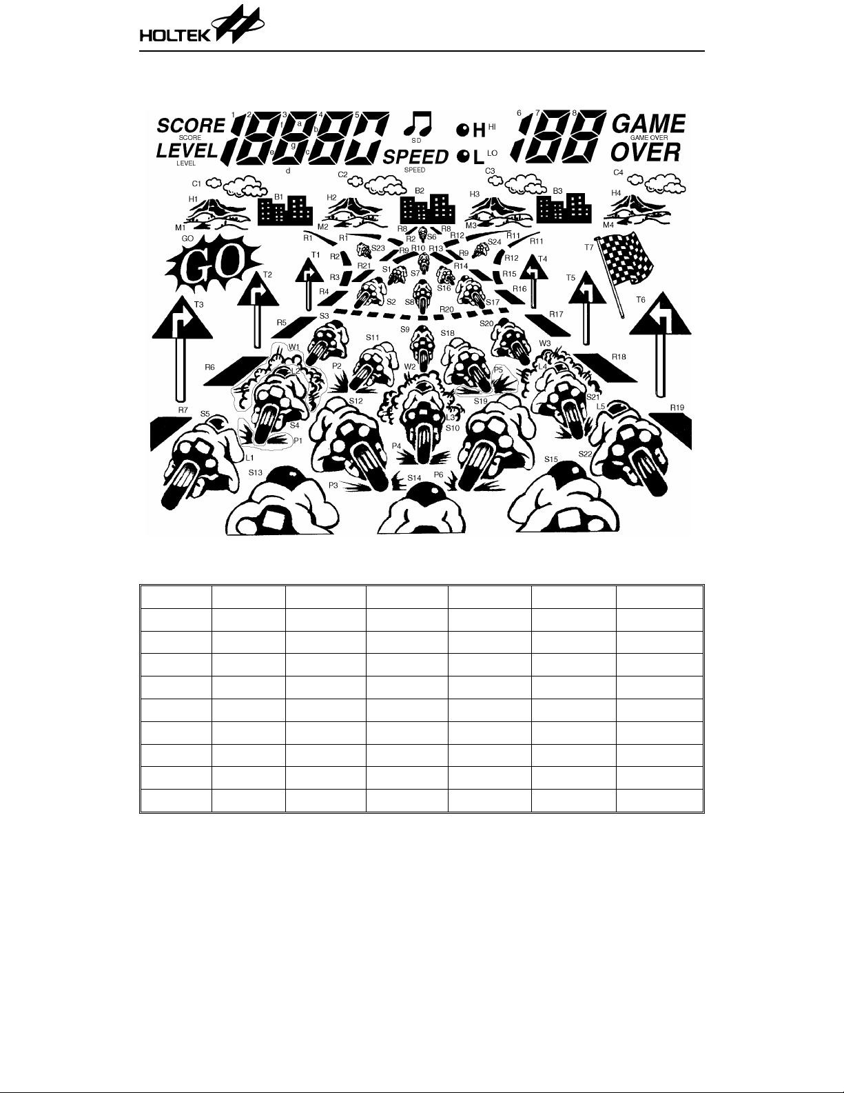
LCD Display Label
HT1137A
LCD Pattern Contrast Table
Pad No. Pin No. COM0 COM1 COM2 COM3 SEGMENT
65 1 R11 B2 SPEED S0 SEG31
64 2 S6 R8 R10 R9 SEG30
63 3 R1 M2 H2 C2 SEG29
62 4 5-0 4c 4b 4a SEG28
61 5 4d 4e 4g 4f SEG27
60 6 T1 3c 3b 3a SEG26
59 7 3d 3e 3g 3f SEG25
58 8 B1 2c 2b 2a SEG24
57 9 2d 2e 2g 2f SEG23
4 19th Nov ’98

HT1137A
Pad No. Pin No. COM0 COM1 COM2 COM3 SEGMENT
56 10 M1 H1 C1 1b,c SEG22
55 11 T3 GO LEVEL SCORE SEG21
54 12 R6 R7 L1 S5 SEG20
53 13 W1 L2 S4 P1 SEG19
52 14 T2 R5 S3 S13 SEG18
51 15 S2 3 R2 R3 R4 SEG17
50 16 S11 P2 S12 P3 SEG16
49 17 S2 S7 S1 R21 SEG15
48 18 W2 P5 S9 S18 SEG14
47 19 L3 S10 P4 S14 SEG13
46 20 S8 S17 S16 R20 SEG12
45 21 W3 S19 P6 S20 SEG11
44 22 L4 S21 P7 S15 SEG10
43 23 R17 R16 R14 R13 SEG9
42 24 T5 R18 L5 S22 SEG8
41 25 T4 R15 R12 S24 SEG7
40 26 R19 T6 C4 GAME OVER SEG6
39 27 H4 8c 8b 8a SEG5
38 28 8d 8e 8g 8f SEG4
37 29 M4 7c 7b 7a SEG3
36 30 7d 7e 7g 7f SEG2
35 31 T7 B3 C3 6b,c SEG1
34 32 M3 H3 L0 Hi SEG0
8 33 COM0 — — — COM0
7 34 — COM1 — — COM1
6 35 — — COM2 — COM2
5 36 — — — COM3 COM3
5 19th Nov ’98

HT1137A
LCD Package Outline Unit : mm
6 19th Nov ’98

Pad Assignment
HT1137A
Chip size: 2790 × 3000 (µm)
* The substrate should be connected to VSS in the PCB layout artwork.
7 19th Nov ’98
2

HT1137A
Pad Coordinates Unit: µm
Pad No. X Y Pad No. X Y
1 –1192.10 1305.20 34 1261.10 –1122.30
2 –1192.10 1169.80 35 1261.10 –979.80
3 –1196.70 1019.80 36 1261.10 –836.30
4 –1261.10 873.70 37 1261.10 –693.80
5 –1261.10 731.20 38 1261.10 –550.30
6 –1261.10 587.70 39 1261.10 –407.80
7 –1261.10 445.20 40 1261.10 –264.30
8 –1261.10 301.70 41 1261.10 –121.80
9 –1261.10 159.20 42 1261.10 21.70
10 –1261.10 15.70 43 1261.10 164.20
11 –1261.10 –126.80 44 1261.10 307.70
12 –1261.10 –270.30 45 1261.10 450.20
13 –1261.10 –412.80 46 1261.10 593.70
14 –1261.10 –556.30 47 1261.10 736.20
15 –1261.10 –698.80 48 1261.10 879.70
16 –1261.10 –842.30 49 1261.10 1022.20
17 –1261.10 –984.80 50 1261.10 1165.70
18 –1261.10 –1128.30 51 1261.10 131 1.20
19 –876.70 –1331.40 52 1001.00 1331.40
20 –719.70 –1331.40 53 858.50 1331.40
21 –542.10 –1241.00 54 715.00 1331.40
22 –406.70 –1241.00 55 572.50 1331.40
23 –276.30 –1241.00 56 429.00 1331.40
24 –140.90 –1241.00 57 286.50 1331.40
25 –10.50 –1241.00 58 143.00 1331.40
26 124.90 –1241.00 59 0.50 1331.40
27 284.90 –1331.40 60 –143.00 1331.40
28 427.40 –1331.40 61 –285.50 1331.40
29 570.90 –1331.40 62 –429.00 1331.40
30 713.40 –1331.40 63 –571.50 1331.40
31 856.90 –1331.40 64 –715.00 1331.40
32 999.40 –1331.40 65 –857.50 1331.40
33 1261.10 –1265.80 66 –990.50 1331.40
8 19th Nov ’98

HT1137A
Absolu te Maxim u m Rating s*
Supply Voltage .......................VDD–0.3V to 5.5V Storage Temperature.................–50°C to 125°C
Input Voltage................. V
*Note: These are stress ra tings on ly. Stresses exceeding the range specifie d under “Ab solute Maxi -
mum Ratings” ma y cause substantial damage to the device. Functional operation of this
device at other conditions beyond those listed in the specification is not implied and prolonged
exposure to extreme condition s may affect device reliability
Electrical Characteristics Ta=25°C
–0.3V to VDD+0.3V Operating Temperature...................0°C to 70°C
SS
Symbol Parameter
V
I
I
V
f
SYS
DD
DD
STB
LCD
Operating Voltage — — 2.4 3 3.3 V
Operating Current 3V No load, f
Standby Current 3V No load — 1 5 µA
LCD Supply Voltage 3V — — 3 — V
Operating Frequency 3V R= 36kΩ — 512 — kHz
Test conditions
V
DD
Conditions
=512kHz — 300 500 µA
SYS
Min. Typ. Max. Unit
9 19th Nov ’98

Application Circuits
Buzzer application
HT1137A
Note: The IC substrate should be connected to VSS in the PCB layout artwork.
10 19th Nov ’98

Speaker application
HT1137A
Notes: The IC substrate should be connected to VSS in the PCB layout artwork.
User can change the volume by changing the resistance 1k
11 19th Nov ’98
Ω~10kΩ.
 Loading...