

Windows 2000 USB+PS/2 Keyboard Encoder
Features
·
Operating voltage: 4.4V~5.5V
·
Operating frequency: f
·
Design for Windows 95/98/NT/2000/XP
·
Phantom key detection
·
Low voltage reset function
·
USB and PS2 modes supported
·
Auto detect USB or PS2 interface
·
USB 1.1 low speed function
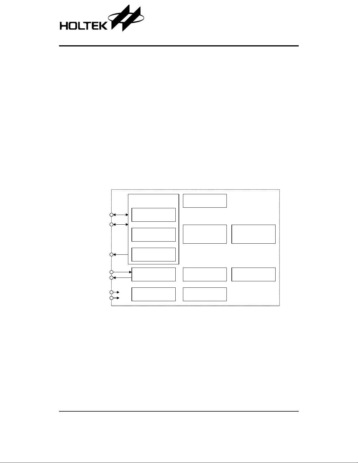
General Description
The HT82K629A can function both in USB and PS2 in
terface environment. For PS2 interface, it supports IBM
PC/AT, IBM PS/2 and all compatible machines and pro
vides a 16-character first-in-first-out buffer in which data
Block Diagram
SYS
=6M
HT82K629A
·
Supports PS2 code set 1 and code set 2
·
Supports multimedia key
·
Supports ACPI key
·
Supports mini-keyboard with Fn key
·
Built-in Watchdog Timer
·
HALT function and wake-up feature for USB mode to
reduce power consumption
·
40-pin DIP package
is stored. For USB interface, it can support the USB
standard request as well as HID class request version
1.1.
-
U S B D + / P S 2 C L K
U S B D - / P S 2 D A T A
V 3 3 O
O S C 1
O S C 2
V D D
V S S
U S B
T r a n s c e i v e r
U S B
R e c e i v e r
U S B
T r a n s m i t t e r
V o l t a g e
R e g u l a t o r
C l o c k
G e n e r a t o r
R C R e s e t
R e g i s t e r S e t
U S B S e r i a l
I n t e r f a c e E n g i n e ( S I E )
& C o n t r o l L o g i c
M a i n
S t a t e M a c h i n e
S u s p e n d
C o n t r o l
H o l t e k 8 - b i t
M i c r o c o n t r o l l e r
F I F O s
Rev. 1.40 1 September 15, 2004
HT82K629A
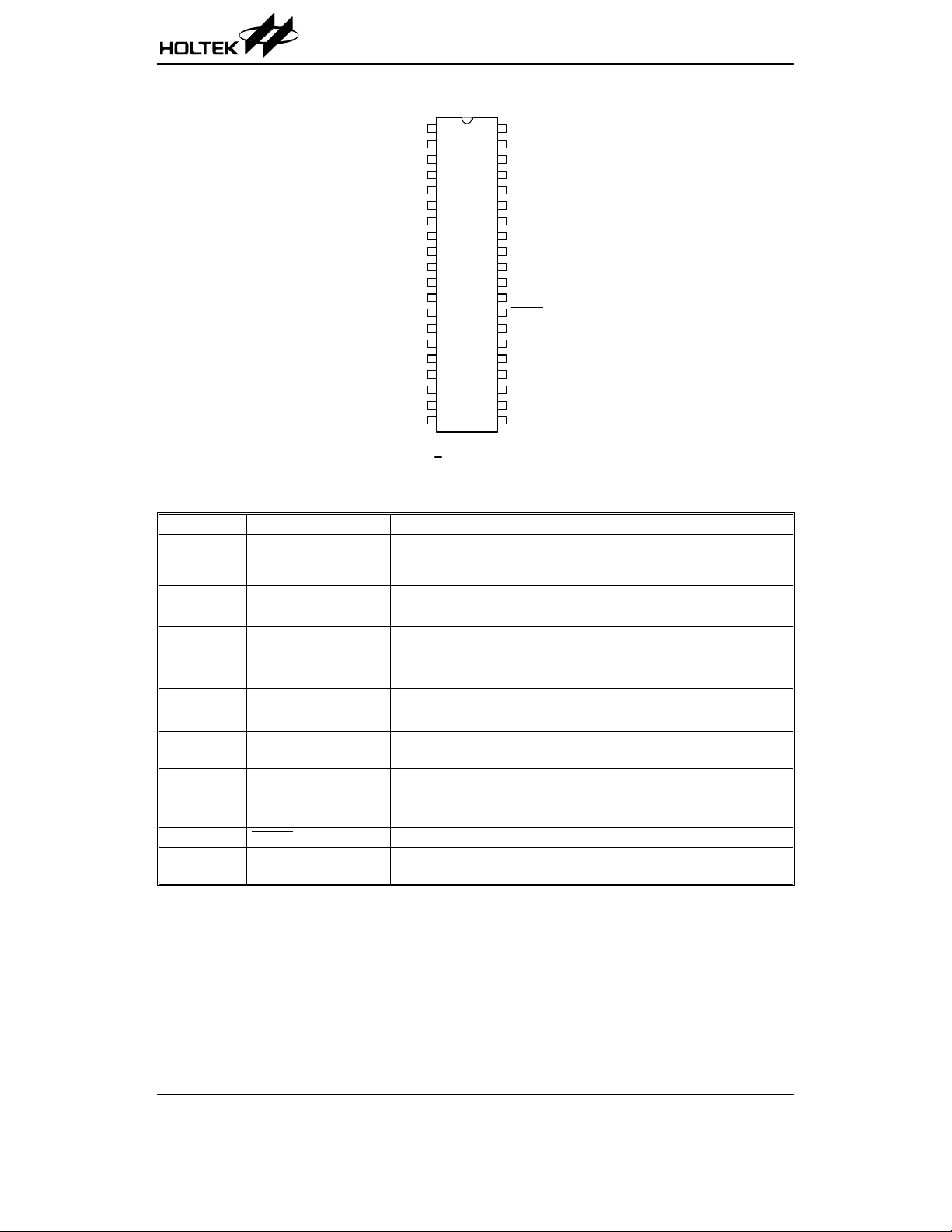
Pin Assignment
C 1 7
1
C 1 6
2
R 3
3
R 2
4
R 1
5
R 0
N U M
C A P S
C 1 2
C 1 3
C 1 4
C 1 5
V D D
V 3 3 O
C 0
C 1
6
7
8
9
1 0
1 1
1 2
1 3
1 4
1 5
1 6
1 7
1 8
1 9
2 0
F n _ S e l
S C R O L L
U S B D + / C L K
U S B D - / D A T A
H T 8 2 K 6 2 9 A
4 0 D I P - A
Pin Description
Pin No. Pin Name I/O Description
1, 2, 11~14
19~26, 31~34
39, 40
3~6, 35~38 R0~R7 I Keyboard matrix scanning input pins
7 Fn_Sel I Mini-keyboard select, the function is enabled if connected to
8 NUM O Num lock indicator
9 CAPS O Caps lock indicator
10 SCROLL O Scroll lock indicator
15 VDD
16 V33O
17 USBD+/CLK I/O
18 USBD-/DATA I/O
27 VSS
28 RESET
29
30
C0~C19 O
OSCO
OSCI
Keyboard matrix scanning output pins
Positive power supply
¾
3.3V regulator output
¾
USBD- or PS2 CLK I/O line
USB or PS2 function is controlled by software control register.
USBD- or PS2 DATA I/O line
USB or PS2 function is controlled by software control register.
¾
Negative power supply, ground
I Schmitt trigger input. Active low.
OIOSCO, OSCI are connected to a 6MHz or 12MHz crystal/resonator for
the internal system clock.
C 1 8
4 0
C 1 9
3 9
R 4
3 8
R 5
3 7
R 6
3 6
R 7
3 5
C 1 1
3 4
C 1 0
3 3
C 9
3 2
C 8
3 1
O S C I
3 0
O S C O
2 9
R E S E T
2 8
V S S
2 7
C 7
2 6
C 6
2 5
C 5
2 4
C 4
2 3
C 3
2 2
C 2
2 1
VSS
.
Absolute Maximum Ratings
Supply Voltage ..........................VSS-0.3V to VSS+6.0V
Input Voltage .............................V
3V to VDD+0.3V
SS-0.
Note: These are stress ratings only. Stresses exceeding the range specified under ²Absolute Maximum Ratings² may
cause substantial damage to the device. Functional operation of this device at other conditions beyond those
listed in the specification is not implied and prolonged exposure to extreme conditions may affect device reliabil
ity.
Rev. 1.40 2 September 15, 2004
Storage Temperature ...........................-50°Cto125°C
Operating Temperature ..............................0°Cto70°C
-
HT82K629A
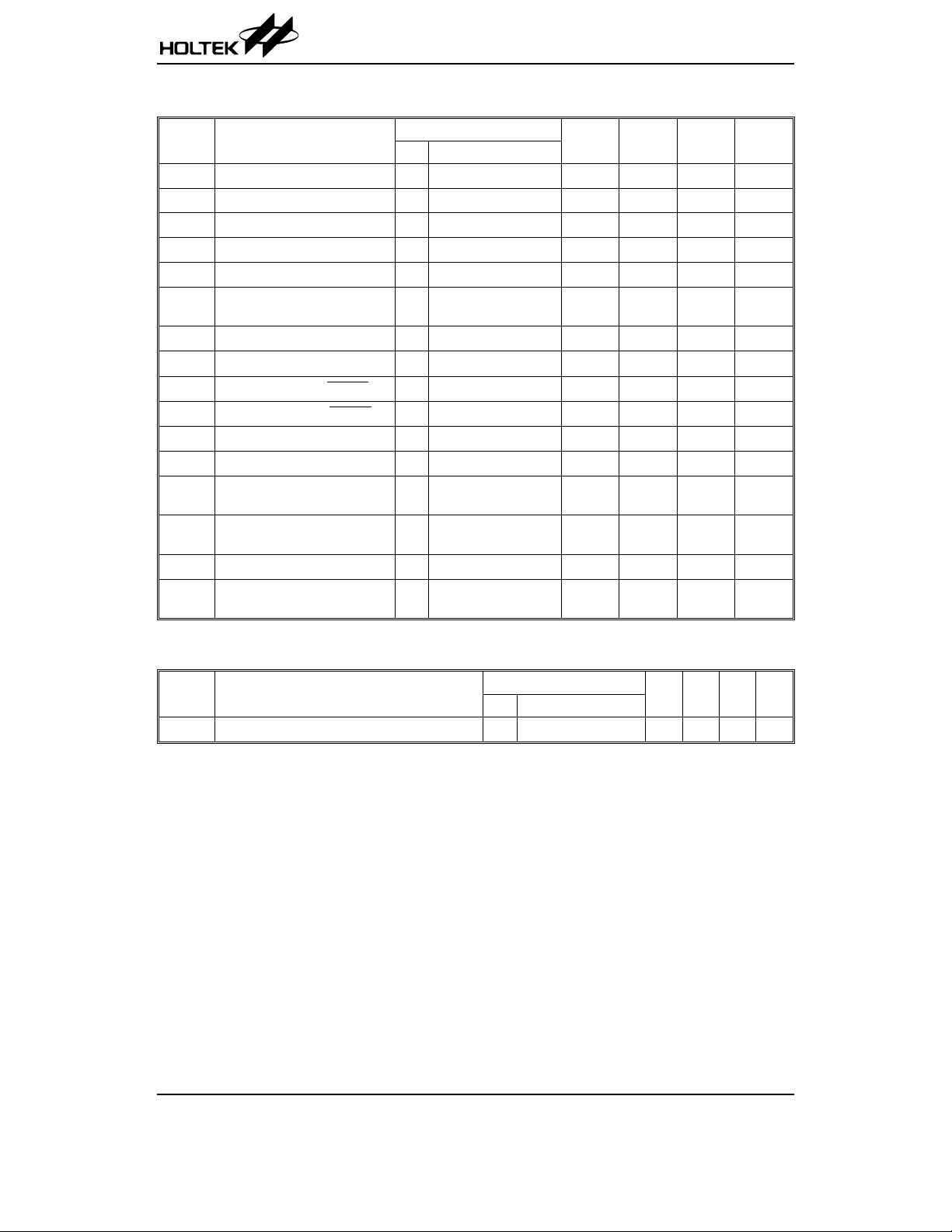
D.C. Characteristics
Symbol Parameter
V
f
I
I
V
R
V
V
V
V
I
I
I
I
I
I
DD
SYS
SB
OP
V330
ph
IL1
IH1
IL2
IH2
OL1
OL2
OL3
OL4
OH1
OH2
Operating Voltage 5V
Operating Frequency 5V f
Standby Current 5V No load,systemHALT
Operating Current 5V
3.3V Regulator Output 5V
Internal Pull-high Resistance
(C0~C19, R0~R7)
Input Low Voltage for I/O Ports 5V
Input HighVoltageforI/OPorts 5V
Input Low Voltage (RESET)5V
Input High Voltage (RESET)5V
Sink Current (Fn_sel) 5V
Sink Current (R0~R7) 5V
Sink Current (C0~C19, NUM,
CAPS, SCROLL)
Sink Current (C0~C19, NUM,
CAPS, SCROLL)
Source Current (Fn_sel) 5V
Source Current (C0~C19,
R0~R7, NUM,CAPS, SCROLL)
Test Conditions
V
DD
SYS
No load, f
I
V33O
5V
V
OL
V
OL
V
5V
OL
V
5V
OL
V
OH
V
5V
OH
Ta=25°C
Conditions
¾
Min. Typ. Max. Unit
4.4
¾
5.5 V
=6MHz 5.9747 6 6.0258 MHz
500
mA
12 mA
kW
0.8 V
5V
0.4V
V
¾
¾
¾
¾
DD
DD
V
V
mA
mA
mA
mA
mA
mA
=-5mA
=0.4V
=0.4V
=0.4V
=3.4V
=3.4V
=3.4V
SYS
¾
¾
¾
¾
¾
=6MHz
¾¾
¾¾
3 3.3 3.6 V
25 50 75
0
2
0
0.9V
DD
¾
¾
¾
¾
10 25
510
24
12 17
-8 -16 ¾
-2 -5 ¾
A.C. Characteristics
Symbol Parameter
f
WDT
Built-in 32kHz RC OSC for Watchdog Timer
Test Conditions
V
DD
Conditions
Min. Typ. Max. Unit
¾¾¾32¾
Ta=25°C
kHz
Rev. 1.40 3 September 15, 2004
Functional Description
Command from the Host
The following table shows the commands that the host
may send and their hexadecimal values.
Command Hex Value
Set/Reset Status Indicators ED
Echo EE
Invalid Command EF
Select Alternate Scan Codes F0
Invalid Command F1
Read ID F2
Set Typematic Rate/Delay F3
Enable F4
Default Disable F5
Set Default F6
Set All Keys - Typematic
Set All Keys - Make/Break
Set All Keys - Make
Set All Keys - Typematic/Make/Break
Set Key Type - Typematic
Set Key Type - Make/Break
Set Key Type - Make
Resend FE
Reset FF
The commands may be sent to the HT82K629A at any
time and the HT82K629A will respond within 25ms except whenperforming the internal diagnostics or executing a Reset command.
EDH - Set/Reset Status Indicators
Three status indicators on the keyboard-Num Lock,
Caps Lock, and Scroll Lock-are accessible by the host.
The HT82K629A activates or deactivates these indica
tors when it receives a valid command-code sequence
from the system. The command sequence begins with
the command byte (hex ED). The HT82K629A responds
to the command byte with ACK, discontinues scanning,
assignments for this option byte are as follow:
Bit Indicator
0 Scroll Lock Indicator
1 Num Lock Indicator
2 Caps Lock Indicator
3~7 Reserved (Must be 0)
If a bit for an indicator is set to 1, the indicator is turned
on. If a bit is set to 0, the indicator is turned off.
F7
F8
F9
FA
FB
FC
FD
HT82K629A
The HT82K629A responds to the option byte with ACK,
sets theindicatorsandif the HT82K629Awas previously
enabled, continues scanning. The status of the indica
tors will reflect the bits in the option byte and can be acti
vated or deactivated in any combination. If another
command is received in place of the option byte, execu
tion of the Set/Reset Mode Indicators command is
stopped, with no change to the indicator status, and the
new command is processed.
Immediately after power-on, the lights default to the off
state. If the Set Default and Default Disable commands
are received, the lamps remain in the state they were in
before the command was received.
EEH - Echo
Echo is a diagnostic aid. When the HT82K629A re
ceives this command, it issues a hex EE response and if
the HT82K629A was previously enabled, continues
scanning.
EFH and F1H - Invalid Command
EFH and F1H are invalid commands and are not sup
ported. If HT82K629A receives one of these and sends
it, the HT82K629A will not acknowledge the command,
but returns a Resend command and continues in its previous scanning state.
F0H - Select Alternate Scan Codes
This commandinstructstheHT82K629Ato select one of
the two sets of scan codes. The HT82K629A acknowledges receipt of this command with ACK, clears both
the output buffer and the typematic key. The host then
sends the option byte and the keyboard responds with
another ACK. An option byte value of hex 01 selects
scan code set 1, hex 02 selects set 2.
An option byte value of hex 00 causes the HT82K629A
to acknowledge with ACK and sends a byte telling the
host which scan code set is currently in use.
-
After establishing the new scan code set, the
HT82K629A returns to the scanning state it was in be
fore receiving the Select Alternate Scan Codes com
mand.
F2H - Read ID
This command requests identification information from
the HT82K629A. The HT82K629A responds with
discontinues scanning and sends the two keyboard ID
bytes hex 83h and ABh. After the output of the second
ID byte, the HT82K629A resumes scanning.
ACK
-
-
-
-
-
-
-
,
Rev. 1.40 4 September 15, 2004
HT82K629A
F3H - Set Typematic Rate/Delay
The host issues the Set Typematic Rate/Delay com
mand to change the typematic rate and delay. The
HT82K629A responds to the command with ACK, stops
scanning and waits for the system to issue the rate/de
lay value byte. The HT82K629A responds to the value
byte with another ACK, sets the rate and delay to the
value indicated, and continues scanning (if it was previ
ously enabled). Bits 6 and 5 indicate the delay, and bits
4, 3, 2, 1 and 0 indicate the rate. Bit7 is always 0. The
delay is equal to 1 plus the binary value bit 6 and 5, mul
tiplied by 250ms±20%.
The period (interval from one typematic output to the
next) is determined by the following equation:
Period = (8+A)*(2^B)*0.00417 seconds.
Where:
A = binary value of bits 2, 1, and 0.
B = binary value of bits 4, and 3.
The typematic rate is 1 for each period and are listed as
follows:
Bit
00000 30.0 10000 7.5
00001 26.7 10001 6.7
00010 24.0 10010 6.0
00011 21.8 10011 5.5
00100 20.0 10100 5.0
00101 18.5 10101 4.6
00110 17.1 10110 4.3
00111 16.0 10111 4.0
01000 15.0 11000 3.7
01001 13.3 11001 3.3
01010 12.0 11010 3.0
01011 10.9 11011 2.7
01100 10.0 11100 2.5
01101 9.2 11101 2.3
01110 8.0 11110 2.1
01111 8.0 11111 2.0
The default values for the HT82K629A are as follows:
Typematic rate= 10.9 characters per second ± 20%
Delay = 500ms±20%
The execution of this command stops without changes
to the existing rate if another command is received in
stead of the rate/delay value byte.
Typematic
Rate ± 20%
Bit
Typematic
Rate ± 20%
F4H - Enable
Upon receipt of this command, the HT82K629A will re
spond with ACK, clears its output buffer, clears the last
typematic key, and starts scanning.
-
F5H - Default Disable
The Default Disable command resets all conditions to
the power on default states. The HT82K629A will
respond with
fault typematic rate/delay, and clears the last typematic
key. The HT82K629A then stops scanning and awaits
further command.
F6H - Set Default
The Set Default command resets all conditions to the
power on default states. The HT82K629A will respond
with ACK, clears its output buffer, sets the default key
typematic rate/delay, and clears the last typematic key
then continues scanning.
F7H, F8H, F9H, FAH - Set All Keys
Since HT82K629A do not support keyboard code set 3
format, so it will not acknowledge the command but re
turns a Resend command and continues in its previous
scanning state.
FBH, FCH, FDH - Set Key Type
Since HT82K629A do not support keyboard code set 3
format, so it will not acknowledge the command but returns a Resend command and continues in its previous
scanning state.
FEH - Resend
The hostsendsthiscommand when it detects an error in
any transmissionfrom the HT82K629A. It is sent only af
ter a data transmission and before the host allows the
next data output. When a Resend is received, the
HT82K629A sends the previous output again (unless
the previous output was Resent, in which case the
HT82K629A sends the last byte before the Resend
command).
-
, clears its output buffer, sets the de
ACK
-
-
-
-
Rev. 1.40 5 September 15, 2004
HT82K629A
Commands to the Host
The following table shows the commands that the
HT82K629A may send to the host and their hexadeci
mal values.
Command Hex Value
Key Detection Error/Overrun 00 (Code Set 2)
Keyboard ID 83AB
Bat Completion Code AA
Bat Failure Core FC
Echo EE
Acknowledge FA
Resend FE
Key Detection Error/Overrun FF (Code Set 1)
00H or FFH - Key Detection Error
The HT82K629Asends a key detection error character if
conditions in the keyboard make it impossible to identify
a switch closure. If the HT82K629A is using scan code
set 1, the code is FFH. For sets 2, the code is 00H.
00H or FFH - Overrun
An overrun character is placed in the HT82K629A buffer
and replaces the last code when the buffer capacity has
been exceeded. The code is sent to the host when it
reaches the top of the buffer queue. If the HT82K629Ais
using scan code set 1, the code is
. For sets 2, the
FFH
code is 00H.
83AbH - Keyboard ID
The keyboard ID consists of 2 bytes, Hex 83AbH. The
HT82K629A responds to the Read ID with ACK, discontinues scanning and sends 2 ID bytes. The low byte is
sent first followed by the high byte. Following the output
of Keyboard ID, the HT82K629A begins scanning.
EEH - Echo
The HT82K629A sends this code in response to an
Echo command.
AAH - BAT Completion Code
Following a satisfactory completion of the BAT, the
HT82K629A sends AAH. Any other code indicates key
board failure.
FCH - BAT Failure Code
If a BAT failure occurs, the HT82K629A sends this code,
discontinues scanning and waits for a host response or
reset.
FEH - Resend
The HT82K629A issues a Resend command following
receipt of an invalid input or any input with incorrect par
ity. If the host sends nothing to the HT82K629A, no re
sponse is required.
Data Communications
·
Data output
-
¨
If CLK=0, no transmission (keyboard is inhibited).
¨
If CLK=1, DATA=0, no transmission (system re
quest to send).
¨
If CLK=1, DATA=1, transmission permitted.
¨
Data will be valid before the trailing edge and be
yond the leading edge of the clock.
¨
The KB checks the clock line for an active level ev
ery 60ms.
¨
If line contention occurs (system brings the clock
low before the tenth clock), set clock=data=high.
·
Data input
¨
The system overrides the clock line for at least
60ms.
¨
The keyboard checks the clock line state at inter
vals of 10ms.
¨
If a system request-to-send is detected, the key
board counts 11 data bits.
¨
Data will be valid before the rising edge and beyond
the falling edge.
¨
After the 10th bit, the keyboard checks for an active
level onthe ²data² line. If the line isactive it is forced
to be inactive, and counts one more bits.
Note: This action signals the system that the
keyboard has received its data. Upon
reception of thissignal, the system returns
to the ready state, in which it can accept
keyboard outputs or goes to the inhibit
state until it is ready.
If the keyboard ²data² line is found to be at an inactive
level followingthe 10th bit, a frame error has occurred,
and the keyboard continues to count until the ²data²
line becomes active. The keyboard then makes the
²data² line inactive and sends a Resend.
Data Stream
Mode 1,2,3
B1
B2
B3
B4
B5
B6
-
B7
B8
B9
B10
B11
Start bit (always 0)
Data bit 0
Data bit 1
Data bit 2
Data bit 3
Data bit 4
Data bit 5
Data bit 6
Data bit 7
Parity bit (odd par)
Stop bit (always 1)
Note: The parity bit is either 1or 0, and the 8 data bits,
plus the parity bit, always have an odd number
of 1ms.
-
-
-
-
-
-
-
Rev. 1.40 6 September 15, 2004
HT82K629A
Key Code Set 1
Key Number
and Symbol
1 ~ ' 29/A9 47 X 2D/AD
2 ! 1 02/82 48 C 2E/AE
3 @ 2 03/83 49 V 2F/AF
4 # 3 04/84 50 B 30/B0
5 $ 4 05/85 51 N 31/B1
6 % 5 06/86 52 M 32/B2
7 ^ 6 07/87 53 < , 33/B3
8 & 7 08/88 54 > . 34/B4
9 * 8 09/89 55 ? / 35/B5
10 ( 9 0A/8A 57 Shift (R) 36/B6
11 ) 0 0B/8B 58 Ctrl (L) 1D/9D
12 _ - 0C/8C 60 Alt (L) 38/B8
13 + = 0D/8D 61 Space 39/B9
14 Keycode14 (*J) 7D/FD 62 Alt (R) E0 38/E0 B8
15 Back Space 0E/8E 64 Ctrl (R) E0 1D/E0 9D
16 Tab 0F/8F 90 Num Lock 45/C5
17 Q 10/90 91 7 Home 47/C7
18 W 11/91 92 4
19 E 12/92 93 1 End 4F/CF
20 R 13/93 96 8
21 T 14/94 97 5 4C/CC
22 Y 15/95 98 2
23 U 16/96 99 0 Ins 52/D2
24 I 17/97 100 * 37/B7
25 O 18/98 101 9 PgUp 49/C9
26 P 19/99 102 6
27 { [ 1A/9A 103 3 PgDn 51/D1
28 } ] 1B/9B 104 . Del 53/D3
29 Keycode29 (*4) 2B/AB 105 - 4A/CA
30 Caps Lock 3A/BA 106 + 4E/CE
31 A 1E/9E 107 Keycode107 (*B) 7E/FE
32 S 1F/9F 108 Enter_R E0 1C/E0 9C
33 D 20/A0 110 ESC 01/81
34 F 21/A1 112 F1 3B/BB
35 G 22/A2 113 F2 3C/BC
36 H 23/A3 114 F3 3D/BD
37 J 24/A4 115 F4 3E/BE
38 K 25/A5 116 F5 3F/BF
39 L 26/A6 117 F6 40/C0
40 : ; 27/A7 118 F7 41/C1
41
²¢
Make/Break Code
28/A8 119 F8 42/C2
Key Number
and Symbol
Make/Break Code
¬
¯
®
4D/CD
4B/CB
48/C8
50/D0
Rev. 1.40 7 September 15, 2004

HT82K629A
Key Number
and Symbol
42 Keycode42 (*5BJ) 2B/AB 120 F9 43/C3
43 Enter_L 1C/9C 121 F10 44/C4
44 Shift (L) 2A/AA 122 F11 57/D7
45 Keycode45 (*5B) 56/D6 123 F12 58/D8
46 Z 2C/AC 125 Scroll Lock 46/C6
Key Number
and Symbol
75
76
79
80
81
83
84
85
86
89
When both shift keys are held down:
key number 75
Insert
Delete
¬
Home
End
¯
PgUp
PgDn
®
Make/Break Code
Base Case
Shift+Num
E0 52
/E0 D2
E0 53
/E0 D3
E0 4B
/E0 CB
E0 47
/E0 C7
E0 4F
/E0 CF
E0 48
/E0 C8
E0 50
/E0 D0
E0 49
/E0 C9
E0 51
/E0 D1
E0 4D
/E0 CD
Left-Shift Right-Shift Num Lock
E0 AA E0 52
/E0 D2 E0 2A
E0 AA E0 53
/E0 D3 E0 2A
E0 AA E0 4B
/E0 CB E0 2A
E0 AA E0 47
/E0 C7 E0 2A
E0 AA E0 4F
/E0 CF E0 2A
E0 AA E0 48
/E0 C8 E0 2A
E0 AA E0 50
/E0 D0 E0 2A
E0 AA E0 49
/E0 C9 E0 2A
E0 AA E0 51
/E0 D1 E0 2A
E0 AA E0 4D
/E0 CD E0 2A
Both Shift
E0 AA E0 B6 E0 52/E0 D2 E0 2A E0 36
Key Number
and Symbol
E0 B6 E0 52
/E0 D2 E0 36
E0 B6 E0 53
/E0 D3 E0 36
E0 B6 E0 4B
/E0 CB E0 36
E0 B6 E0 47
/E0 C7 E0 36
E0 B6 E0 4F
/E0 CF E0 36
E0 B6 E0 48
/E0 C8 E0 36
E0 B6 E0 50
/E0 D0 E0 36
E0 B6 E0 49
/E0 C9 E0 36
E0 B6 E0 51
/E0 D1 E0 36
E0 B6 E0 4D
/E0 CD E0 36
Make/Break Code
E0 2A E0 52
/E0 D2 E0 AA
E0 2A E0 53
/E0 D3 E0 AA
E0 2A E0 4B
/E0 CB E0 AA
E0 2A E0 47
/E0 C7 E0 AA
E0 2A E0 4F
E0 CF E0 AA
E0 2A E0 48
E0 C8 E0 AA
E0 2A E0 50
/E0 D0 E0 AA
E0 2A E0 49
/E0 C9 E0 AA
E0 2A E0 51
E0 D1 E0 AA
E0 2A E0 4D
E0 CD E0 AA
Key Number
and Symbol
95 / E0 35/E0 B5 E0 AA E0 35/E0 B5 E0 2A E0 B6 E0 35/E0 B5 E0 36
When both shift keys are held down: key number 95
Key Number
and Symbol
124 Print Screen E0 2A E0 37/E0 B7 E0 AA E0 37/E0 B7 54/D4
Key Number
and Symbol
126 Pause E1 1D 45 E1 9D C5 E0 46 E0 C6
This key is not typematic, all associated scan codes occur on the make code.
Key Number
and Function
56 (*BJ) Brazil BA0 73/F3 Make/Break/Typematic
131 (*J) Japanese J131 7B/FB Make/Break/Typematic
132 (*J) Japanese J132 79/F9 Make/Break/Typematic
133 (*J) Japanese J133 70/F0 Make/Break/Typematic
150 Korea KC-L
151 Korea KC-R
Base Left-Shift Right-Shift
Both Shift
E0 AA E0 B6 E0 35/E0 B5 E0 2A E0 36
Base Shift/Ctrl Alt
Base Ctrl
Make/Break Code Default
F1/-
F0/-
Make
Make
Rev. 1.40 8 September 15, 2004

HT82K629A
Key Number
and Function
ACPI Power E0 5E/E0 DE Make/Break
ACPI Sleep E0 5F/E0 DF Make/Break
ACPI Wake-up E0 63/E0 E3 Make/Break
Windows Key L Win
Windows Key R Win
Windows Key APP
Multimedia Key E-Mail E0 6C/E0 EC Make/Break
Multimedia Key WWW Home E0 32/E0 B2 Make/Break
Multimedia Key WWW Favorites E0 66/E0 E6 Make/Break
Multimedia Key WWW Search E065/E0 E5 Make/Break
Multimedia Key WWW Refresh E0 67/E0 E7 Make/Break
Multimedia Key WWW Stop E0 68/E0 E8 Make/Break
Multimedia Key WWW Forward E0 69/E0 E9 Make/Break
Multimedia Key WWW Back E0 6A/E0 EA Make/Break
Multimedia Key Media E0 6D/E0 ED Make/Break
Multimedia Key Play/Pause E0 22/E0 A2 Make/Break
Multimedia Key Stop E0 24/E0 A4 Make/Break
Multimedia Key Prev Track E0 10/E0 90 Make/Break
Multimedia Key Next Track E0 19/E0 99 Make/Break
Multimedia Key Volume+ E0 30/E0 B0 Make/Break/Typematic
Multimedia Key
Multimedia Key Mute E0 20/E0 A0 Make/Break
Multimedia Key My Computer E0 6B/E0 EB Make/Break
Multimedia Key Calculator E0 21/E0 A1 Make/Break
Multimedia Key Screen save E0 26/E0 A6 Make/Break
Multimedia Key Rec E0 1E/E0 9E Make/Break
Multimedia Key Rew E0 17/E0 97 Make/Break
Multimedia Key Minimize E0 2D/E0 AD Make/Break
Multimedia Key Eject E0 11/E0 91 Make/Break
*4- 104 Keyboard Only
*5- 105 Keyboard Only
Volume-
Make/Break Code Default
E0 5B
/E0 DB
E0 5C
/E0 DC
E0 5D
/E0 DD
E0 2E/E0 AE Make/Break/Typematic
*B - 107 Keyboard Only
*J - 109 Keyboard Only
Make/Break/Typematic
Make/Break/Typematic
Make/Break/Typematic
Rev. 1.40 9 September 15, 2004

HT82K629A
Key Code Set 2
Key Number
and Symbol
1 ~ ' 0E/F0 0E 47 X 22/F0 22
2 ! 1 16/F0 16 48 C 21/F0 21
3 @ 2 1E/F0 1E 49 V 2A/F0 2A
4 # 3 26/F0 26 50 B 32/F0 32
5 $ 4 25/F0 25 51 N 31/F0 31
6 % 5 2E/F0 2E 52 M 3A/F0 3A
7 ^ 6 36/F0 36 53 < , 41/F0 41
8 & 7 3D/F0 3D 54 > . 49/F0 49
9 * 8 3E/F0 3E 55 ? / 4A/F0 4A
10 ( 9 46/F0 46 57 Shift (R) 59/F0 59
11 ) 0 45/F0 45 58 Ctrl (L) 14/F0 14
12 _ - 4E/F0 4E 60 Alt (L) 11/F0 11
13 + = 55/F0 55 61 Space 29/F0 29
14 Keycode14 (*J) 6A/F0 6A 62 Alt (R) E0 11/E0 F0 11
15 Back Space 66/F0 66 64 Ctrl (R) E0 14/E0 E0 F0 14
16 Tab 0D/F0 0D 90 Num Lock 77/F0 77
17 Q 15/F0 15 91 7 Home 6C/F0 6C
18 W 1D/F0 1D 92 4
19 E 24/F0 24 93 1 End 69/F0 69
20 R 2D/F0 2D 96 8
21 T 2C/F0 2C 97 5 73/F0 73
22 Y 35/F0 35 98 2
23 U 3C/F0 3C 99 0 Ins 70/F0 70
24 I 43/F0 43 100 * 7C/F0 7C
25 O 44/F0 44 101 9 PgUp 7D/F0 7D
26 P 4D/F0 4D 102 6
27 { [ 54/F0 54 103 3 PgDn 7A/ F0 7A
28 } ] 5B/F0 5B 104 . Del 71/F0 71
29 Keycode29 (*4) 5D/F0 5D 105
30 Caps Lock 58/F0 58 106 + 79/F0 79
31 A 1C/F0 1C 107 Keycode107 (*B) 6D/F0 6D
32 S 1B/F0 1B 108 Enter_R E0 5A/E0 F0 5A
33 D 23/F0 23 110 ESC 76/F0 76
34 F 2B/F0 2B 112 F1 05/F0 05
35 G 34/F0 34 113 F2 06/F0 06
36 H 33/F0 33 114 F3 04/F0 04
37 J 3B/F0 3B 115 F4 0C/F0 0C
38 K 42/F0 42 116 F5 03/F0 03
39 L 4B/F0 4B 117 F6 0B F0 0B
40 : ; 4C/F0 4C 118 F7 83/F0 83
41
²¢
Make/Break Code
52/F0 52 119 F8 0A/F0 0A
Key Number
and Symbol
Make/Break Code
¬
¯
®
-
6B/F0 6B
75/F0 75
72/F0 72
74/ F0 74
7B/F0 7B
Rev. 1.40 10 September 15, 2004

HT82K629A
Key Number
and Symbol
42 Keycode42 (*5BJ) 5D/F0 5D 120 F9 01/F0 01
43 Enter_L 5A/F0 5A 121 F10 09/F0 09
44 Shift (L) 12/F0 12 122 F11 78/F0 78
45 Keycode45 (*5B) 61/F0 61 123 F12 07/F0 07
46 Z 1A/F0 1A 125 Scroll Lock 7E/F0 7E
Key Number
and Symbol
75
76
79
80
81
83
84
85
86
89
When both Shift keys are held down:
key number 75
Insert
Delete
¬
Home
End
¯
PgUp
PgDn
®
Make/Break Code
Base Case
Shift+Num
E0 70
/E0 F0 70
E0 71
/E0 F0 71
E0 6B
/E0 F0 6B
E0 6C
/E0 F0 6C
E0 69
/E0 F0 69
E0 75
/E0 F0 75
E0 72
/E0 F0 72
E0 7D
/E0 F0 7D
E0 7A
/E0 F0 7A
E0 74
/E0 F0 74
Left-Shift Right-Shift Num Lock
E0 F0 12 E0 70
/E0 F0 70 E0 12
E0 F0 12 E0 71
/E0 F0 71 E0 12
E0 F0 12 E0 6B
/E0 F0 6B E0 12
E0 F0 12 E0 6C
/E0 F0 6C E0 12
E0 F0 12 E0 69
/E0 F0 69 E0 12
E0 F0 12 E0 75
/E0 F0 75 E0 12
E0 F0 12 E0 72
/E0 F0 72 E0 12
E0 F0 12 E0 7D
/E0 F0 7D E0 12
E0 F0 12 E0 7A
/E0 F0 7A E0 12
E0 F0 12 E0 74
/E0 F0 74 E0 12
Both Shift
E0 AA E0 B6 E0 52/E0 D2 E0 2A E0 36
Key Number
and Symbol
E0 F0 59 E0 70
/E0 F0 70 E0 59
E0 F0 59 E0 71
/E0 F0 71 E0 59
E0 F0 59 E0 6B
/E0 F0 6B E0 59
E0 F0 59 E0 6C
/E0 F0 6C E0 59
E0 F0 59 E0 69
/E0 F0 69 E0 59
E0 F0 59 E0 75
/E0 F0 75 E0 59
E0 F0 59 E0 72
/E0 F0 72 E0 59
E0 F0 59 E0 7D
/E0 F0 7D E0 59
E0 F0 59 E0 7A
/E0 F0 7A E0 59
E0 F0 59 E0 74
/E0 F0 74 E0 59
Make/Break Code
E0 12 E0 70
/E0 F0 70 E0 F0 12
E0 12 E0 71
/E0 F0 71 E0 F0 12
E0 12 E0 6B
/E0 F0 6B E0 F0 12
E0 12 E0 6C
/E0 F0 6C E0 F0 12
E0 12 E0 69
/E0 F0 69 E0 F0 12
E0 12 E0 75
/E0 F0 75 E0 F0 12
E0 12 E0 72
/E0 F0 72 E0 F0 12
E0 12 E0 7D
/E0 F0 7D E0 F0 12
E0 12 E0 7A
/E0 F0 7A E0 F0 12
E0 12 E0 74
/E0 F0 74 E0 F0 12
Key Number
and Symbol
95 / E0 4A/E0 F0 4A E0 F0 12 E0 4A/E0 F0 4A E0 12 E0 F0 59 E0 4A/E0 F0 4A E0 59
When both Shift keys are held down:
key number 95
Key Number
and Symbol
124 Print Screen E0 12 E0 7C/E0 F0 7C E0 F0 12 E0 7C/E0 F0 7C 84/F0 84
Key Number
and Symbol
126 Pause E1 14 77 E1 F0 14 F0 77 E0 7E E0 F0 7E
This key is not typematic, all associated scan codes occur on the make code.
Key Number
and Function
56 (*BJ) Brazil BA0 51/F0 51 Make/Break/Typematic
131 (*J) Japanese J131 67/F0 67 Make/Break/Typematic
132 (*J) Japanese J132 64/F0 64 Make/Break/Typematic
133 (*J) Japanese J133 13/F0 13 Make/Break/Typematic
150 Korea KC-L
151 Korea KC-R
Base Left-Shift Right-Shift
Both Shift
E0 F0 12 E0 F0 59 E0 4A/E0 F0 4A E0 12 E0 59
Base Shift/Ctrl Alt
Base Ctrl
Make/Break code Default
F1/-
F2/-
Make
Make
Rev. 1.40 11 September 15, 2004

HT82K629A
Key Number
and Function
ACPI Power E0 37/E0 F0 37 Make/Break
ACPI Sleep E0 3F/E0 F0 3F Make/Break
ACPI Wake-up E0 5E/E0 F0 5E Make/Break
Windows Key L Win
Windows Key R Win
Windows Key APP
Multimedia Key E-Mail E0 48/E0 F0 48 Make/Break
Multimedia Key WWW Home E0 3A/E0 F0 3A Make/Break
Multimedia Key WWW Favorites E0 18/E0 F0 18 Make/Break
Multimedia Key WWW Search E0 10/E0 F0 10 Make/Break
Multimedia Key WWW Refresh E0 20/E0 F0 20 Make/Break
Multimedia Key WWW Stop E0 28/E0 F0 28 Make/Break
Multimedia Key WWW Forward E0 30/E0 F0 30 Make/Break
Multimedia Key WWW Back E0 38/E0 F0 38 Make/Break
Multimedia Key Media E0 50/E0 F0 50 Make/Break
Multimedia Key Play/Pause E0 34/E0 F0 34 Make/Break
Multimedia Key Stop E0 3B/E0 F0 3B Make/Break
Multimedia Key Prev Track E0 15/E0 F0 15 Make/Break
Multimedia Key Next Track E0 4D/E0 F0 4D Make/Break
Multimedia Key Volume+ E0 32/E0 F0 32 Make/Break/Typematic
Multimedia Key
Multimedia Key Mute E0 23/E0 F0 23 Make/Break
Multimedia Key My Computer E0 40/E0 F0 40 Make/Break
Multimedia Key Calculator E0 2B/E0 F0 2B Make/Break
Multimedia Key Screen save E0 4B/E0 F0 4B Make/Break
Multimedia Key Rec E0 1C/E0 F0 1C Make/Break
Multimedia Key Rew E0 43/E0 F0 43 Make/Break
Multimedia Key Minimize E0 22/E0 F0 22 Make/Break
Multimedia Key Eject E0 1D/E0 F0 1D Make/Break
*4- 104 Keyboard Only
*5- 105 Keyboard Only
Volume-
Make/Break code Default
E0 1F
/E0 F0 1F
E0 27
/E0 F0 27
E0 2F
/E0 F0 2F
E0 21/E0 F0 21 Make/Break/Typematic
*B - 107 Keyboard Only
*J - 109 Keyboard Only
Make/Break/Typematic
Make/Break/Typematic
Make/Break/Typematic
Rev. 1.40 12 September 15, 2004

Timing Diagrams
Data Output
( 1 ) ( 3 ) ( 3 )
C L K
( 2 )
D A T A S t a r t B i t B i t 0 P a r i t y B i t S t o p B i t
1 s t
C L K
T 3 T 4
T 1 T 2
2 n d
C L K
HT82K629A
( 3 )
( 3 ) ( 4 )
1 0 t h
C L K
1 1 t h
C L K
( 5 ) ( 7 )
T 5
( 6 )
Keyboard Data Input
( 1 )
C L K
D A T A S t a r t B i t B i t 0 P a r i t y B i t S t o p B i t
T i m i n g P a r a m e t e r
T 1
D A T A t r a n s i t i o n t o t h e f a l l i n g e d g e o f C L K
T 2
R i s i n g e d g e o f C L K t o D A T A t r a n s i t i o n
T 3
D u r a t i o n o f C L K i n a c t i v e
T 4
D u r a t i o n o f C L K a c t i v e
T 5
T i m e t o a u x i l i a r y d e v i c e i n h i b i t a f t e r c l o c k 1 1 t o e n s u r e t h a t
t h e a u x i l i a r y d e v i c e d o e s n o t s t a r t a n o t h e r t r a n s m i s s i o n .
( 4 )
( 2 )
I / O
I n h i b i t
T i m i n g P a r a m e t e r
D u r a t i o n o f C L K i n a c t i v e
T 7
T 8
D u r a t i o n o f C L K a c t i v e
T 9 T i m e f r o m i n a c t i v e t o a c t i v e C L K t r a n s i t i o n , u s e d t o t i m e
w h e n t h e a u x i l i a r y d e v i c e s a m p l e s D A T A
1 s t
C L K
T 7 T 8
( 3 )
2 n d
C L K
T 9
( 5 ) ( 7 )
C L K
9 t h
( 5 )
1 0 t h
C L K
( 6 )
M i n / M a x
s e c
5 / 2 5
m
5 / T 4 - 5 ms e c
3 0 / 5 0
m
3 0 / 5 0
m
> 0 / 5 0
m
1 1 t h
C L K
M i n / M a x
3 0 / 5 0 ms e c
3 0 / 5 0 ms e c
s e c
5 / 2 5
m
s e c
s e c
s e c
( 8 )
Rev. 1.40 13 September 15, 2004

HT82K629A
USB Interface
HT82K629A has one control pipe for USB configuration, command and status type communication flows between cli
ents software (BIOS, Win 98, Win 2K, Win ME and Win XP etc.) and HT82K629A keyboard encoder device. It also has
two interrupt pipes to send the HID page 7 Standard keyboard code and ACPI, multimedia key correspondingly to cli
ents software. For LED output, it comes from the control pipe.
HT82K629A can support USB standard request and HID class request. It is shown in the following table:
Item Command Description Support
USB get endpoints status such as
STALL, wake-up, power information
USB clear device STALL, or remote
wake-up function.
USB set device STALL, or remote
wake-up function.
USB get HT82K629A device, configura
tion information
USB get HT82K629A string descriptor
(option command)
USB set device descriptor data
(option command)
USB get HT82K629A HID, report
information
USB set device descriptor data
(option command)
USB get keyboard, ACPI, multimedia
data
USB get boot or report protocol for
endpoint
USB set boot or report protocol for end
point
Yes
Yes
Yes
Yes
No, response STALL
No, response STALL
Yes
No, response STALL
Yes
Yes (default report
protocol)
Yes
USB1.1 Standard Request
HID1.1 Class Request
Get_Status
Clear Feature
Set Feature
Set Address USB set device address Yes
Get_Descriptor
Set_Descriptor
Get_Configuration USB get device, configuration value Yes (default 0 value)
Set_Configuration USB set device, configuration value Yes
Get_Interface USB get device, interface No, response STALL
Set_Interface USB set device, interface No, response STALL
SYNCH_Frame USB output frame number No, response STALL
Get_Descriptor
Set_Descriptor
Get_Report
Set_Report Set keyboard LED Yes
Get_Protocol
Set_Protocol
Get_Idle USB set keyboard idle rate Yes (default 500ms)
Set_Idle USB get keyboard idle rate Yes
-
-
Keyboard Output Format for USB Interface
·
Endpoint1 - standard keyboard endpoint
The Endpoint1 of HT82K629Ais used to send standard keyboard key code and is configured asinterrupt pipe. It con
tain 8 bytes data. The first byte is a modified byte to send the left and right of the (Shift, ALT, CTRL and WIN) key sta
tus. It is in bitmap format. The second byte is a reserved byte. The third to eight bytes are used to send the other HID
page7 key codes (except for the above modified key). The key code list is shown as the USB HID standard keyboard
code table.
Bit 7 Bit 6 Bit 5 Bit 4 Bit 3 Bit 2 Bit 1 Bit 0
R_Win R_ALT R_Shift R_Ctrl L_Win L_ALT L_Shift L_Ctrl
1: Key is pressed
0: Key is released
The Modified Byte Definition
Rev. 1.40 14 September 15, 2004
-
-

HT82K629A
·
Endpoint2 - ACPI, multimedia key endpoint
The Endpoint2 of the HT82K629A is used to send ACPI and multimedia key and is configured as interrupt pipe. For
ACPI, there are two bytes data, the first byte is report ID byte = 01H, the second is ACPI key status.
Byte No. Bit 7 Bit6 Bit 5 Bit 4 Bit 3 Bit 2 Bit 1 Bit 0
1 00000001b
2 00000b Wake-up Sleep Power
1: Key is pressed
0: Key is released
The ACPI Key Byte Definition
For multimedia keys, there are four bytes data, the first byte is report ID byte = 02H,
The second to fourth is the multimedia key status.
Byte No. Bit 7 Bit6 Bit 5 Bit 4 Bit 3 Bit 2 Bit 1 Bit 0
1 00000010b
2 Eject CD Stop
3
4 Rewind Record Minimize
1: Key is pressed
0: Key is released
·
USB LED output
Client Software Output one byte LED data to HT82K629A, to control the LED status, through Endpoint0. The format
is shown in the following table:
Bit 7 Bit 6 Bit 5 Bit 4 Bit 3 Bit 2 Bit 1 Bit 0
1: LED on
0: LED off
Refresh
WWW
Stop
00000b Scroll Lock Cap Lock Num Lock
Prev.
Track
WWW
Forward
The Multimedia Key Bytes Definition
Next
Track
WWW
Back
My
Computer
Play/Pause Mute Volume- Volume+
WWW
Home
Screen
Save
WWW
Favorites
Calculator Explorer Media
WWW
Search
E-Mail
USB HID Standard Keyboard Code Table
Key Number and Symbol HID Page HID Code Key Number and Symbol HID Page HID Code
1 ~ ` 073554> . 0737
2! 1071E55? / 0738
3 @ 2 07 1F 56 Keycode56 (*BJ) 07 87
4 # 3 07 20 57 Shift (R) 07 E5
5 $ 4 07 21 58 Ctrl (L) 07 E0
6 % 5 07 22 60 Alt (L) 07 E2
7 ^ 6 07 23 61 Ctrl (L) 07 2C
8 & 7 07 24 62 Alt (R) 07 E6
9 * 8 07 25 64 Ctrl (R) 07 E4
10 ( 9 07 26 75 Insert 07 49
11 ) 0 07 27 76 Delete 07 4C
12 _ - 07 2D 79 Left Arrow 07 50
13 + = 07 2E 80 Home 07 4A
Rev. 1.40 15 September 15, 2004

HT82K629A
Key Number and Symbol HID Page HID Code Key Number and Symbol HID Page HID Code
14 Keycode14 (*J) 07 89 81 End 07 4D
15 Back Space 07 2A 83
16 Tab 07 2B 84
17 Q 07 14 85 PgUp 07 4B
18 W 07 1A 86 PgDn 07 4E
19 E 07 08 89
20 R 07 15 90 Num Lock 07 53
21 T 07 17 91 7 Home 07 5F
22 Y 07 1C 92 4
23 U 07 18 93 1 End 07 59
24 I 07 0C 95 / 07 54
25 O 07 12 96 8
26 P 07 13 97 5 07 5D
27 { [ 07 2F 98 2
28 } ] 07 30 99 0 Ins 07 62
29 Keycode29 (*4) 07 31 100 * 07 55
30 Caps Lock 07 39 101 9 PgUp 07 61
31 A 07 04 102 6
32 S 07 16 103 3 PgDn 07 5B
33 D 07 07 104 . Del 07 63
34 F 07 09 105 - 07 56
35 G 07 0A 106 + 07 57
36 H 07 0B 107 Keycode107 (*B) 07 85
37 J 07 0D 108 Enter_R 07 58
38 K 07 0E 110 ESC 07 29
39 L 07 0F 112 F1 07 3A
40 : ; 07 33 113 F2 07 3B
41
42 Keycode42 (*5BJ) 07 32 115 F4 07 3D
43 Enter_L 07 28 116 F5 07 3E
44 Shift (L) 07 E1 117 F6 07 3F
45 Keycode45 (*5B) 07 64 118 F7 07 40
46 Z 07 1D 119 F8 07 41
47 X 07 1B 120 F9 07 42
48 C 07 06 121 F10 07 43
49 V 07 19 122 F11 07 44
50 B 07 05 123 F12 07 45
51 N 07 11 124 Print Screen 07 46
52 M 07 10 125 Scroll Lock 07 47
53 < , 07 36 126 Pause 07 48
²¢
07 34 114 F3 07 3C
¯
®
¬
¯
®
07 52
07 51
07 4F
07 5C
07 60
07 5A
07 5E
Rev. 1.40 16 September 15, 2004
HT82K629A
Key Number and Symbol HID Page HID Code Key Number and Symbol HID Page HID Code
*4- 104 Keyboard Only
*5- 105 Keyboard Only
Key Number and Symbol HID Page HID Code
131 (*J) Japanese J131 07 8B
132 (*J) Japanese J132 07 8A
133 (*J) Japanese J133 07 88
150 Korea KC-L, Key_Hangul 07 90
151 Korea KC-R, Key_Hanja 07 91
ACPI Power 01 81
ACPI Sleep 01 82
ACPI Wake-up 01 83
Windows Key L WIN 07 E3
Windows Key R WIN 07 E7
Windows Key APP 07 65
Multimedia Key Number and Symbol HID Page HID Code
E-Mail 0C 018A
WWW Home 0C 0223
WWW Favorites 0C 022A
WWW Search 0C 0221
WWW Refresh 0C 0227
WWW Stop 0C 0226
WWW Forward 0C 0225
WWW Back 0C 0224
Media 0C 0183
Play/Pause 0C 00CD
CD Stop 0C 00B7
Prev Track 0C 00B6
Next Track 0C 00B5
Volume+ 0C 00E9
Volume- 0C 00EA
Mute 0C 00E2
My Computer 0C 0194
Calculator 0C 0192
The following keys need a driver
Explorer (Internet Browser) 0C 0196
Screen Save 0C 019E
Record 0C 00B2
Rewind 0C 00B4
Minimize 0C 0206
*B - 107 Keyboard Only
*J - 109 Keyboard Only
Rev. 1.40 17 September 15, 2004

Function Key Usage
Status
Key
Location
7 &7 Home 7 7
Fn
OFF OFF ON OFF OFF ON ON ON
Num
Lock
Fn
Num
Lock
Fn
Num
Lock
HT82K629A
Fn
Num
Lock
8*8
9 (9 PgUp 9 9
0)0 * * 0
UU
II 5 I
OO
PP - - P
J J End 1 J
KK
L L PgDn 3 L
:; :; + + :;
M M Ins 0 M
>. >. Del . >.
?/ ?/ / / ?/
Enter Enter (L) Enter(R) Enter(R) Enter(L)
F1/F11 F1 F11 F1 F11
F2/F12 F2 F12 F2 F12
¬
®
¯
88
4U
6O
2K
F10/
ScrLock
/PgUp
¯/PgDn ¯
¬/Home ¬
®/End ®
Rev. 1.40 18 September 15, 2004
F10 ScrLock F10 ScrLock
Page Up
Page Down
Home
End
¯
¬
®
Page Up
Page Down
Home
End

Key Matrix
C0/PB0
C1/PB1
C2/PB2
C3/PB3
C4/PB4
C5/PB5
C6/PB6
C7/PB7
C8/PD0
C9/PD1
C10/PD2
C11/PD3
C12/PD4
C13/PD5
C14/PD6
C15/PD7
C16/PC4
C17/PC5
C18/PC6
C19/PC7
HT82K629A
R0/PA0 R1/PA1 R2/PA2 R3/PA3 R4/PA4 R5/PA5 R6/PA6 R7/PA7
PAUSE
126
Q
17
W
18
E
19
R
20
U
23
24
O
25
7(Home)
91
|(\)
14
SCROLL
125
P
26
Screen
Save
KC-L
150
Media E-mail
My
Computer
Wake-up
+
106
9(PgUp)
101
8()
96
Pre Track Stop Play/Pause CTRL-R64Next Track CTRL-L
I
TAB
16
CAPS
30
F3
114
T
21
Y
22
](})
28
F7
118
4(¬)
92
BACK
15
[({)
27
WIN-L Rec Rew Min Eject
Calculator
SHIFT-L44SHIFT-R
.
107
6(®)
102
5
97
A
31
S
32
D
33
F
34
J
37
K
38
L
39
1(End)
93
\(|)
29
Vol- ALT-L
;(:)
40
WIN-R 00 000 F2/F12 KC-R
WWW
Home
/
Page Up¯/Page Down
57
ENTER-R
108
3(PgDn)
103
2(¯)
98
ESC
110
|(\)
45
F4
115
G
35
H
36
F6
117
SPACE61NUM LOCK
F11
122
60
'(²)
41
WWW
Back
WWW
Search
83
.(Del)
104
0(Ins)
99
46
47
48
49
52
,(<)
53
.(>)
54
90
ENTER-L
43
Vol+ ALT-R
42
WWW
Forward
Home
100
95
|(\)
¬/
Z
X
C
V
M
*
/
N-CHG
131
CHG
132
ROMA
133
50
51
56
84
123
62
55
WWW
Stop
END
79
105
89
B
N
\(-)
APP
¯
F12
/(?)
®/
¬
-
®
58
1
112
113
5(%)
6
7
=(+)
13
119
DEL76POWER
120
Mute
12
WWW
Refresh
Explorer
F1/F11 FN
HOME
80
PgUp
85
75
¢(~)
F1
F2
6(^)
F8
F9
_(-)
INS
116
2
2(@)
3
4
5
8
9
10
121
PRINT
SCREEN
11
Scroll
151
WWW
Bkmk
END
81
PgDn
86
SLEEP
F5
1(!)
3(#)
4($)
7(&)
8(*)
9(¢(¢)
F10
0(¢)¢)
F10/
Rev. 1.40 19 September 15, 2004
The following table shows which key needs a driver in the different OS
OS Key Need Drive
·
Media, My computer, Calculator
·
E-mail, WWW Home, WWW Back, WWW Forward, WWW Stop, WWW Refresh,
MS DOS, Win95
Win 98
Win ME,Win 2K, Win XP
WWW Favorite, WWW Search
·
Vol-, Vol+, Mute, Pre Track, CD Stop, Play/Pause, Next Track
·
Rec, Rew, Min, Eject, Screen Save, Explorer
·
Power, Wake-up, Sleep
·
Media, My computer, Calculator
·
E-mail, WWW Home, WWW Back, WWW Forward, WWW Stop, WWW Refresh,
WWW Favorite, WWW Search
·
Vol-, Vol+, Mute, Pre Track, CD Stop, Play/Pause, Next Track
·
Rec, Rew, Min, Eject, Screen Save, Explorer
·
Rec, Rew, Min, Eject, Screen Save, Explorer
HT82K629A
Rev. 1.40 20 September 15, 2004

Application Circuits
HT82K629A
O S C I
O S C O
R E S E T
V S S
C 1 8
C 1 9
C 1 1
C 1 0
R 4
R 5
R 6
R 7
C 9
C 8
C 7
C 6
C 5
C 4
C 3
C 2
4 0
3 9
3 8
3 7
3 6
3 5
3 4
3 3
3 2
3 1
6 M H z
3 0
2 9
2 8
2 7
2 6
2 5
2 4
2 3
2 2
2 1
F 0 . 1mF
0 . 1
m
1 0 0 k
W
1 0 k
W
V D D
U S B -
U S B +
V S S
U S B C O N
1
C 1 7
2
C 1 6
3
R 3
4
R 2
5
R 1
6
R 0
7
F n S e l e c t
8
N U M
9
C A P S
1 0
S C R O L L
1 1
C 1 2
1 2
C 1 3
1 3
C 1 4
1 4
C 1 5
1 5
V D D
1 6
V 3 3 O
1 7
U S B D + / C L K
1 8
U S B D - / D A T A
1 9
C 0
2 0
C 1
H T 8 2 K 6 2 9 A
F n _ S e l = 1 o r f l o a t i n g : d i s a b l e s M i n i - k e y b o a r d f u n c t i o n
F n _ S e l = 0 : e n a b l e s M i n i - k e y b o a r d f u n c t i o n
V D D
3 3 p F
N u m L o c k
D 1
D 3
S c r o l l L o c k
M C U V D D
1 . 5 k
W
3 3 p F
2 2
W
F 0 . 1mF
0 . 1
m
2 2
W
M C U V D D
0 . 0 1mF1 0mF
C a p s L o c k
D 2
2 2
W
1
2
3
4
Note: For single side PCB, the GND should be routed first. Avoid routing the GND line and VDD line with jumping
wires.
The GND and VDD lines should be as wide as possible, also it is recommended that the GND and VDD lines
are placedin an empty area, in order to increase their area. Wherever possiblethe GND plane should surround
pins such as OSCI, OSCO, VDD, V330, RESET
etc and other related circuits to minimize the noise effects.
The GND/VDD loop area should be minimized. Try to keep GND and VDD lines parallel.
The external 22W resistor and 0.01mF capacitor connected to the VDD pin should be placed as close as possible to the VDD pin.
Allow room in the layout for the 0.1mF capacitor that is connected to the VDD pin. This capacitor should be con
nected as closeas possible to the VDD pin. The function of this capacitor isto filter out high frequency noise.
The lines connecting the OSCI and OSCO pins to the crystal must be kept as short as possible to minimize any
cross coupling of noise from these pins.
The 0.1mF capacitor connected to the RESET
pin should be placed as close as possible to the RESET pin. The
function of this capacitor is to filter out high frequency noise to minimize the possibility of a glitch on this line
causing a false reset.
The 0.1mF capacitor connected to the V33O pin should be placed as close as possible to the V33O pin.
The USBD+ and USBD- lines to the USB connector should be kept as short as possible and should not be
placed close to the other lines to reduce the possibility of noise coupling into other lines. The externally con
nected 1.5kW resistor connected to the USBD- pin should be placed as close to as possible the USBD- pin.
The USB cable should preferably have proper shielding.
-
-
Rev. 1.40 21 September 15, 2004

Package Information
40-pin DIP (600mil) outline dimensions
HT82K629A
A
4 0
B
1
C
D
E
Symbol
F G
Min. Nom. Max.
A 2045
B 535
C 145
D 125
E16
F50
G
¾
H 595
I 635
2 1
2 0
Dimensions in mil
¾
¾
¾
¾
¾
¾
100
¾
¾
H
a
I
a 0°¾15°
2065
555
155
145
20
70
¾
615
670
Rev. 1.40 22 September 15, 2004

Holtek Semiconductor Inc. (Headquarters)
No.3, Creation Rd. II, Science Park, Hsinchu, Taiwan
Tel: 886-3-563-1999
Fax: 886-3-563-1189
http://www.holtek.com.tw
Holtek Semiconductor Inc. (Taipei Sales Office)
4F-2, No. 3-2, YuanQu St., Nankang Software Park, Taipei 115, Taiwan
Tel: 886-2-2655-7070
Fax: 886-2-2655-7373
Fax: 886-2-2655-7383 (International sales hotline)
HT82K629A
Holtek Semiconductor Inc. (Shanghai Sales Office)
7th Floor, Building 2, No.889, Yi Shan Rd., Shanghai, China 200233
Tel: 021-6485-5560
Fax: 021-6485-0313
http://www.holtek.com.cn
Holtek Semiconductor Inc. (Shenzhen Sales Office)
5/F, Unit A, Productivity Building, Cross of Science M 3rd Road and Gaoxin M 2nd Road, Science Park, Nanshan District,
Shenzhen, China 518057
Tel: 0755-8616-9908, 8616-9308
Fax: 0755-8616-9533
Holtek Semiconductor Inc. (Beijing Sales Office)
Suite 1721, Jinyu Tower, A129 West Xuan Wu Men Street, Xicheng District, Beijing, China 100031
Tel: 010-6641-0030, 6641-7751, 6641-7752
Fax: 010-6641-0125
Holtek Semiconductor Inc. (Chengdu Sales Office)
709, Building 3, Champagne Plaza, No.97 Dongda Street, Chengdu, Sichuan, China 610016
Tel: 028-6653-6590
Fax: 028-6653-6591
Holmate Semiconductor, Inc. (North America Sales Office)
46729 Fremont Blvd., Fremont, CA 94538
Tel: 510-252-9880
Fax: 510-252-9885
http://www.holmate.com
Copyright Ó 2004 by HOLTEK SEMICONDUCTOR INC.
The information appearing in this Data Sheet is believed to be accurate at the time of publication. However, Holtek as
sumes no responsibility arising from the use of the specifications described. The applications mentioned herein are used
solely for the purpose of illustration and Holtek makes no warranty or representation that such applications will be suitable
without further modification, nor recommends the use of its products for application that may present a risk to human life
due to malfunction or otherwise. Holtek¢s products are not authorized for use as critical components in life support devices
or systems. Holtek reserves the right to alter its products without prior notification. For the most up-to-date information,
please visit our web site at http://www.holtek.com.tw.
-
Rev. 1.40 23 September 15, 2004
 Loading...