


e-ICE Users Guide
August, 2012
Copyright © 2011 by HOLTEK SEMICONDUCTOR INC. All rights reserved. Printed in Taiwan. No part of
this publication may be reproduced, stored in a retrieval system, or transmitted in any form by any means,
electronic, mechanical photocopying, recording, or otherwise without the prior written permission of
HOLTEK SEMICONDUCTOR INC.

e-ICE User’s Guide
2
e-ICE Introduction ....................................................................................................................... 3
e-ICE Naming Rules .................................................................................................................... 3
e-ICE Actual Picture .................................................................................................................... 4
MEV Board ............................................................................................................................................4
DEV Board............................................................................................................................................. 4
PEV Board .............................................................................................................................................5
e-ICE Operation ........................................................................................................................... 6
IDE3000 Software Update .....................................................................................................................6
Accompanying MCU Tools.....................................................................................................................6
DEV Power Supply Options...................................................................................................................7
Connect the EV Board ........................................................................................................................... 8
Connect to the USB Port and Simulation will begin Using the IDE3000 ................................................7
e-ICE Operating Notes ................................................................................................................ 9
HT-IDE3000 Version ..............................................................................................................................9
System Frequency................................................................................................................................. 9
Voltage and Current............................................................................................................................. 10
e-ICE Counting Cycle, Interrupt Points, Halt Instruction and Trace ..................................................... 11
e-ICE Reset ......................................................................................................................................... 11
ADC Sampling .....................................................................................................................................12
WDT Overflow Reset ........................................................................................................................... 12
PRM Register ......................................................................................................................................12
e-ICE HIRC Trim Operating Description .................................................................................. 12
After Manufacture with no Prior Frequency Calibration then Manual Adjustment will be Required......12
After Manufacture if Calibration is Implemented by the DEV then no Manual Adjustment is Required 15
M1001A Limited Version Operating Limitations..................................................................... 15
Stack Overflow.....................................................................................................................................15
Halt Instruction.....................................................................................................................................16
Configuration Option IO/RES Setting................................................................................................... 16
DEV Board.................................................................................................................................. 17
128-Pin DEV Board .............................................................................................................................17
208-Pin DEV Board .............................................................................................................................18
PEV Board .................................................................................................................................. 19

e-ICE User’s Guide
3
e-ICE User’s Guide
e-ICE Introduction
The e-ICE is Holtek’s new generation MCU hardware emulator which provides
considerable enhancements over its predecessors. Some features include:
Uses a Real Chip structure to provide simulation results much closer to that of an
actual MCU device
Can setup up to 64K of easily adjusted breakpoints
Simulation hardware can be powered using a variable power supply with a range of
2.2V~5.5V allowing pin voltage levels to be compatible with actual device.
Simplified emulator circuitry, facilitates easier maintenance and greater stability
Uses a USB interface for PC communication with greater ease of use
e-ICE Naming Rules
The e-ICE is comprised of an MEV Board, DEV Board and Peripheral Board. The
following is the naming rules for each part:
MEV Board Part No. Naming Rule
Naming Rules have six digits, e.g. M1001C M 1 001 C
type code No. version
DEV Board Part No. Naming Rule
Naming Rules have six digits, e.g. D1001C D 1 001 C
type code No. version
Peripheral Board Part No. Naming Rule
Naming Rules have six digits, e.g. P1001B P 1 001 B
type code No. version
e-ICE User’s Guide
4
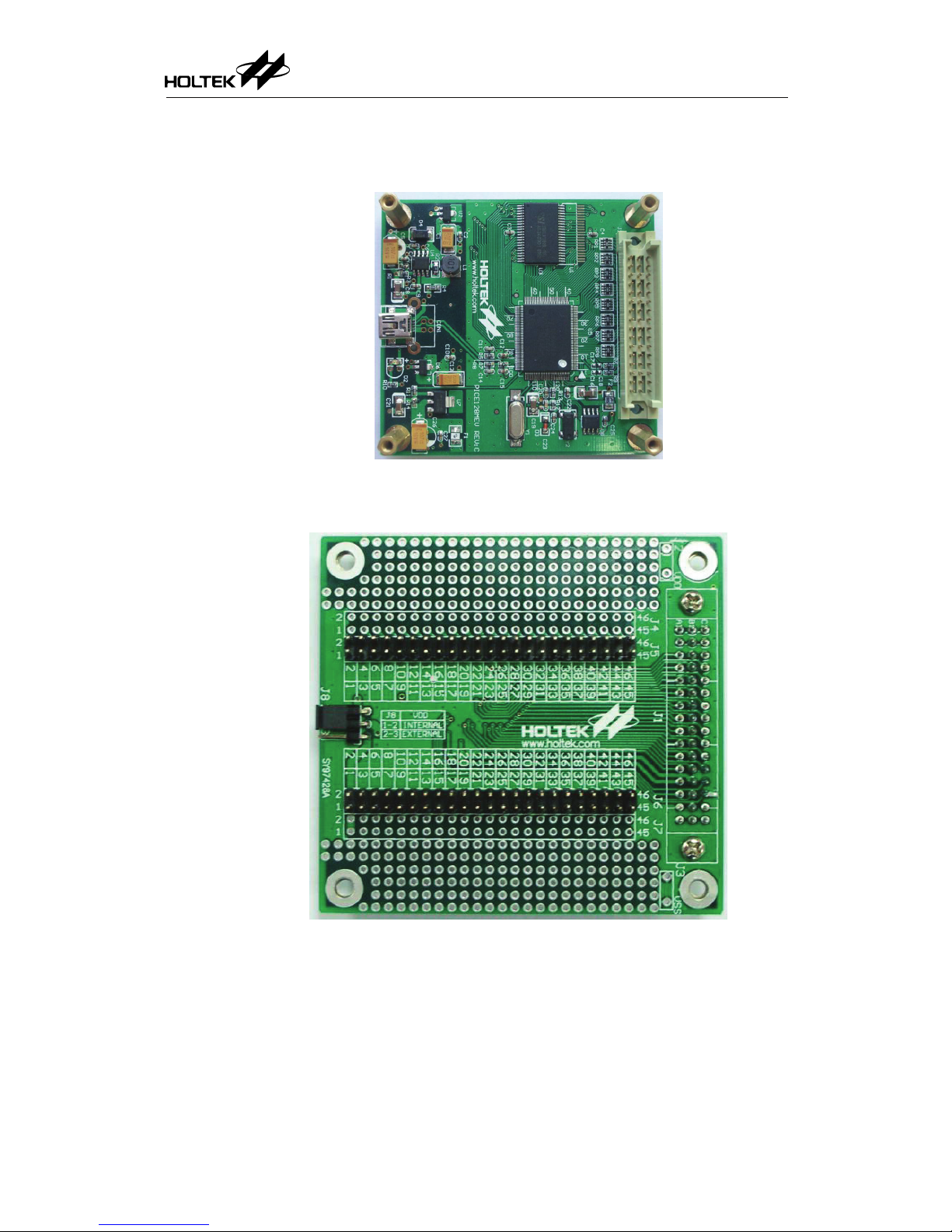
e-ICE Actual Picture
MEV Board
Figure 1 M1001C MEV Board
DEV Board
Figure 2 D1001A Top Layer
e-ICE User’s Guide
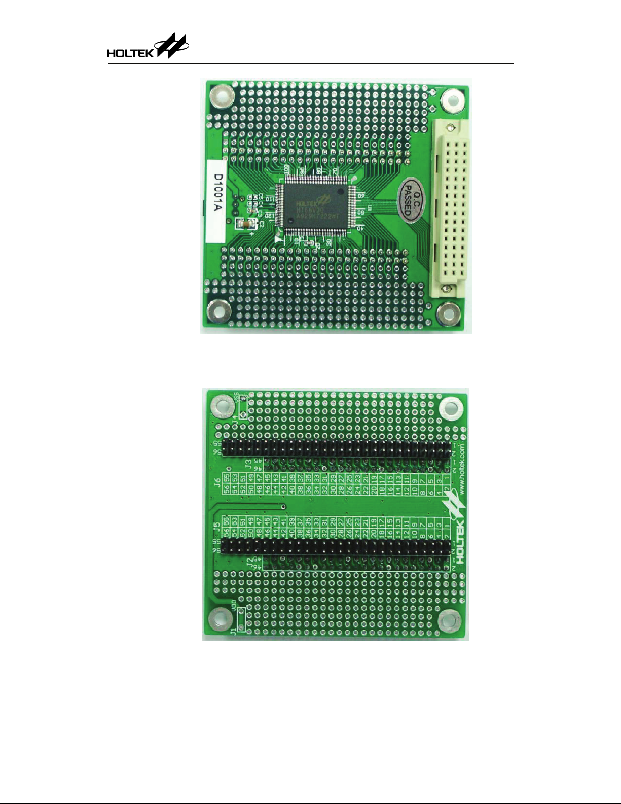
5
Figure 3 D1001A Bottom Layer
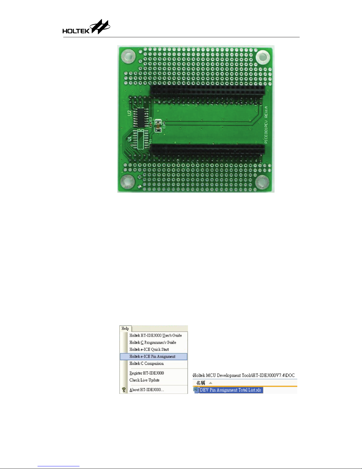
PEV Board
Figure 4 P1001A Top Layer
e-ICE User’s Guide
6
Figure 5 P1001A Bottom Layer
e-ICE Operation
IDE3000 Software Update
The new emulator continues to use the original HT-IDE3000 software, however it should
be upgraded to at least Version V7.1 which offers support for the e-ICE.
This can be downloaded at the Holtek official website.
Download the latest IDE3000 ensuring that is the correct version.
Accompanying MCU Tools
Open the accompanying MCU tools Excel table.
There are two options provided:
1. Execute the HT-IDE3000 V7.4, click “menu/help/Holtek e-ICE pin mapping table.”
2. Open the “DOC\DEV Pin Assignment Total List.xls” under HT-IDE3000.
Figure 6 Open the DEV Pin Assignment Total List.xls table
In the Excel table, press “DEV name” or “MCU name” to check.

e-ICE User’s Guide
7
Figure 7 Partial DEV Total List
Example: HT66F50 Emulator: M1001C, D1003C.
HT66FU50 Emulator: M1001C, D1003C + P1001B
Note: M1001C is the upgraded version of the M1001B and M1001A.
D1003C is the upgraded version of the D1003A and D1003B.
P1001B is the upgraded version of the P1001A.
Check the User Guide
Click the User Guide hyperlink to jump to the related User Guide text file.
Eg: Click and the HT66F50 User Guide will pop up.
Check the Pin Assignment
Click the link under the DEV Board No. for the corresponding PIN assignment table.
Eg: Click and the HT66F50 DEV PIN assignment will appear as shown
in the table below.
Figure 8 HT66F50 Pin Assignment
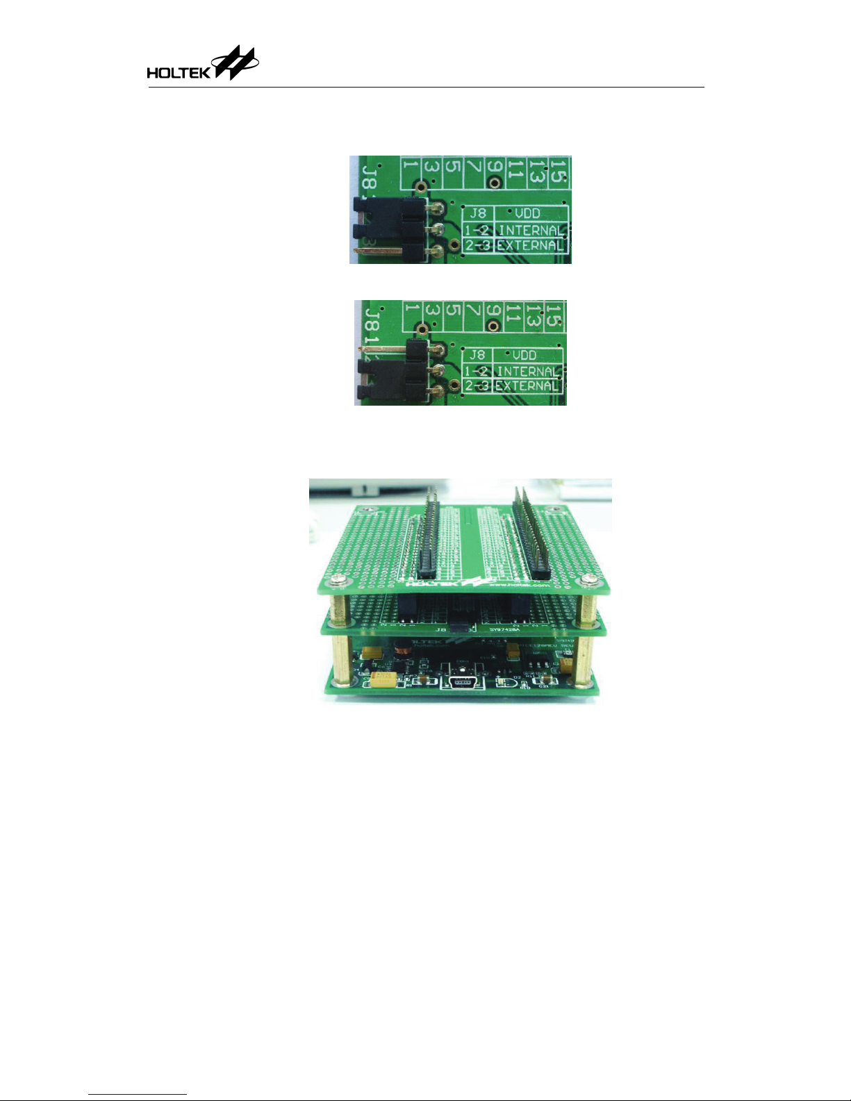
DEV Power Supply Options
Jumper J8 on the DEV is used to select the VDD power supply:
e-ICE User’s Guide
8
1-2 selects the internal VDD (Figure 9)
2-3 selects an external power supply provided on VEXT (Figure 10)
Figure 9 Connect jumper between 1-2 for internal VDD power supply
Figure10 Connect jumper between 2-3 for external VEXT power supply
Connect the EV Board
Figure 11 MEV Board+DEV Board+PEV Board
Layer Order:
Bottom Layer: MEV Board
Middle Layer: DEV Board
Top Layer: PEV Board -- not always necessary
Ensure screws are firmly secured for good contact.
Connect to the USB Port and Simulation will begin Using the
IDE3000

e-ICE User’s Guide
9
e-ICE Operating Notes
HT-IDE3000 Version
Make sure the IDE3000 in use is the latest version before using the e-ICE.
Check the e-ICE version from “Help\About HT-IDE3000…” in the IDE3000 function list.
If the version is V7.4 or above, when the IDE3000 is activated, the IDE will auto-detect
the version info and suggest if it is necessary to upgrade, or click “Help\Check Live
Update…” for a manual upgrade.
Figure 12 About HT-IDE3000
Figure 13 Help
System Frequency
For simulation convenience, check the red box as shown in the figure below to select
an MEV board supplied DEV operating frequency source. During e-ICE simulation an
externally connected HXT, ERC or LXT oscillator is not permitted. However, the
required oscillator should be connected for actual IC applications.
Figure 14 SysFreq Frequency Setup Window

e-ICE User’s Guide
10
If the red frame is unchecked, the DEV operating frequency will not be supplied by the
MEV Board.
If the red frame is checked, the MEV Board provides frequencies as listed in the following table.
The MEV Board provided frequencies are integer divisions of 24MHz : 24 / N (N=2, 3, 4 … 60) and
32.768kHz.
Divider 24/2 24/3 24/4 24/5 24/6
Frequency 12MHz 8 MHz 6 MHz 4.8 MHz 4MHz
Divider 24/7 24/8 24/9 24/10 24/11
Frequency 3.428571MHz 3 MHz 2.666666MHz 2.4 MHz 2.181818MHz
Divider 24/12 24/13 24/14 24/15 24/16
Frequency 2 MHz 1.846153MHz 1.714285MHz 1.6MHz 1.5 MHz
Divider 24/17 24/18 24/19 24/20 24/21
Frequency 1.411764MHz 1.333333MHz 1.263157MHz 1.2 MHz 1.142857MHz
Divider 24/22 24/23 24/24 24/25 24/26
Frequency 1.090909MHz 1.043478MHz 1MHz 960kHz 923.077kHz
……
Divider 24/57 24/58 24/59 24/60 RTC
Frequency 421.052kHz 413.793kHz 406.779kHz 400kHz 32.768kHz
Table 1 MEV Board provided frequencies
The MEV Board can offer frequency division ratios as listed in Table 1. For other
frequency selections an external oscillator is required.
The e-ICE can support a max system frequency of 20MHz. However as the MEV Board
is unable to divide a 20MHz frequency, external components will be required.
Voltage and Current
The e-ICE operating voltage can be set freely to a range of 2.2V~5.5V which is
different from the HT-ICE which can only operate at either 5V or 3.3V.
As the figure below shows, ensure that the emulator operates at the correnct voltage
using the SysVolt setting.
Figure 15 SysVolt Frequency Setup Window
When the e-ICE uses an external VDD as the power supply, ensure that the external
power is stable and is not greater than 5.5V before connecting it to the VEXT and VSS
pins of the DEV Board. The J8 jumper should be connected between pins 2-3. When
switching the external power supply on or off, it is possible that instantaneous large
voltages or currents may be generated. Therefore remember to remove the external
power from the DEV Board before shutting down the power.
When jumper J8 is connected between pins 1-2, then power will be supplied by the
internal VDD. Here the maximum current consumption is 300mA. If the power
consumption exceeds this value, then jumper J8 must be connected between pins 2-3
and power supplied on VEXT using an external power supply.

e-ICE User’s Guide
11
e-ICE Counting Cycle, Interrupt Points, Halt Instruction and Trace
HT-ICE e-ICE
Cycle count 2 Bytes 4 Bytes
Breakpoint Setup
Max of three
Can be set during free run
Can be setup in Data and Program Memory
No restriction for the number
Cannot be set during free run
Can be setup only in Program Memory
Writer Function Supported Not Supported
HALT Instruction
Can be located anywhere Cannot be located at the last address (0x1fff)
of the Program Memory Bank0
Trace Function
Can select Normal Mode (INT+Main) or
execute independently in the INT/Main mode
With Trigger and Qualify functions
Only Normal mode selectable. No Trigger and
Qualify function
Table 2 HT-ICE and e-ICE Differences
e-ICE Reset
Taking the HT66F50 device as an example, when using the e-ICE, the configuration
options related to the reset function is: “ICE_Reset” and “I/O or RESB Function”.
The conditions are as follows.
ICE_Reset
Note 1
I/O or RESB Function Pin Function
1
SYSTEM
RESB
None
Note 2
2
SYSTEM
I/O
IO
3
IC_RESET_PIN RESB
Reset
Note 3
4
IC_RESET_PIN I/O
IO
Table 3 Reset & IO Configuration
Note1: A connection must be made to the e-ICE for the IC_Reset option to be shown.
Note2: In this condition, it is not necessary for the Reset pin to be connected to an
external Reset circuit. To implement a reset select the IDE3000
icon.
Note3: In this condition, the Reset pin must be connected to an external Reset circuit or
the IDE3000 will show the following message during compilation:
Error (D1014): Unable to write resource option
Reset pin circuit:
Figure 16 Reset Circuit

e-ICE User’s Guide
12
ADC Sampling
In order to increase ADC sampling stability, it is recommended to add a 0.1F
non-polarized capacitor between each ADC channel and GND. The capacitor should be
located as closed to the DEV as possible.
If this capacitor is not connected, there may be 0~5 data value errors between the
sampled and the expected value which accounts for about 0~7mV.
Additionally, it is recommended to use an external power supply for VDD instead of using
the internal power. To do this, set jumper J8 to position 2-3 and connect an accurate
external power supply which will help to increase the ADC sample accuracy.
WDT Overflow Reset
If the WDT, in the normal mode, is required to overflow repeatedly, it may stop
overflowing after a period of time and the following condition may occur:
Reset and power on reset may fail.
Unable to STOP
These are ICE restrictions. To rectify, re-plug the USB interface and re-compile the
program to continue operation.
PRM Register
For those MCUs with the PRM registers, the MCUs with the pin switch function can be
applied with more flexibility. If no pin function should be changed, the PRM register
setting can be ignored and it default value is 00H. If the pin function is to be changed,
enable the pin switch function and give values according to actual needs. For details refer
to the datasheet on Holtek’s official website.
e-ICE HIRC Trim Operating Description
After Manufacture with no Prior Frequency Calibration then Manual
Adjustment will be Required
In this situation, after connecting to the e-ICE, the final configuration option selection is
“ICE_HIRC_Trim”. The IDE3000 provides a trimming interface for users to execute an
HIRC Trim function.
Note:
1. Each time a Project Rebuild is executed, a HIRC Trim should be re-executed.
2. Each time the HIRC frequency is changed, a HIRC Trim should be re-executed.
3. Each time the DEV Board is changed, a HIRC Trim should be re-executed.
4. After the Trim process has completed, if the HIRC frequency and DEV Board are not
changed, then the relevant information regarding the Trim will be stored automatically
without needing to re-trim again.

e-ICE User’s Guide
13
HIRC Trim Operating Procedures:
Connect the e-ICE to a PC, execute IDE3000.exe and start a new operation with Trim
HIRC.
The Configuration Options include setting the operating voltage and the HIRC as the
system frequency using the following steps:
Set the operating voltage SysVolt according to actual requirements.
Configure the SysFreq to have the system frequency provided by the internal DEV
or by an external oscillator supplied by the user
Set V
DD
(for Internal RC selections) according to actual requirements
Set the Internal RC according to actual requirements
Configure OSC to have a system frequency to be provided by the internal DEV HIRC

e-ICE User’s Guide
14
Click the “ICE_HIRC Trim” from the Option menu, then scroll and use an oscilloscope
to check that Fsys is the desired HIRC frequency.
The Flat Tuning is the HIRC coarse adjustment while the Fine tuning is the HIRC
fine adjustment as shown as figure 17.
As scrolling approaches the Max value the frequency will increase
The present HIRC frequency can be measured on the Fsys pin on the DEV (A13 of
J1) as shown in figure 18.
The oscilloscope detection method is shown in figure 19.
Figure 17 HIRC Trimming Interface
Figure 18 f
SYS
Measuring Point
Every time the Trim value is adjusted
the IDE3000 will download the
temporary operating file to the e-ICE
A13: f
SYS
Coarse adjustment
Fine adjustment

e-ICE User’s Guide
15
Figure 19 Oscilloscope Detection
After Manufacture if Calibration is Implemented by the DEV then no
Manual Adjustment is Required
In this situation, after connecting to the e-ICE, the final configuration option selection is
not “ICE_HIRC_Trim.”
If it is necessary to check the present HIRC frequency accuracy, then set the options to
HIRC and measure according to figure 18 and 19 after downloading the compiled data.
M1001A Limited Version Operating Limitations
The following operating limitations only occur on the M1001A. The present MEV Board
has corrected these issues.
Stack Overflow
When an interrupt occurs, two false levels will be added to the stack which will create an
erroneous stack display. However it will not affect the program execution. To resolve this
issue, turn off the Detect Stack Overflow in the IDE3000 to close the message box.
[Options] [Project Settings] [Debu g Option]

e-ICE User’s Guide
16
Figure 20 Debug Option
Halt Instruction
The Halt instruction cannot be located at the last address (0x1fff) of Program Memory
ROM Bank0.
If a WDT overflow occurs during a Halt condition, it is possible that an erroneous stack
overflow may occur.
Pressing Stop during a Halt condition may result in incorrect PC values.
The first instruction after waking up from a Halt condition may execute correctly. To
resolve this issue add a NOP instruction to avoid this problem.
Executing a HALT instruction using Single Step may cause an immediate wake up.
Configuration Option IO/RES Setting
When the “PXn/RES Pin Option in the Configuration Options is set as an I/O PIN, the I/O
Reset, Poweron Reset, and Stop will all be invalid.

e-ICE User’s Guide
17
DEV Board
128-Pin DEV Board

e-ICE User’s Guide
18
208-Pin DEV Board

e-ICE User’s Guide
19
PEV Board

e-ICE User’s Guide
20
Holtek Semiconductor Inc. (Headquarters)
No.3, Creation Rd. II Science Park. Hsinchu, Taiwan
Tel: 886-3-563-1999
FAX: 886-3-563-1189
http://www.holtek.com
Holtek Semiconductor Inc. (Taipei Sales Offeice)
4F-2, No. 3-2, YuanQu St., Nankang Software Park, Taipei 115, Taiwan
Tel: 886-2-2655-7070
FAX: 886-2-2655-7373
FAX: 886-2-2655-7383 (International sales hotline)
Holtek Semiconductor Inc. (Shenzhen Sales Offeice)
5F, Unit A, Productivity Building, No.5 Gaoxin M 2nd Road, Nanshan District, Shenzhen, China 518057
Tel: 86-755-8616-9908
FAX: 86-755-8616-9722
Holmate Semiconductor(USA), Inc. (North America Sales Office)
46712 Fremont Blvd., Fremont, CA 94538
Tel: 1-510-252-9880
FAX: 1-510-252-9885
Http:// www.holmate.com
Copyright 2011 by HOLTEK SEMICONDUCTOR INC.
The information appearing in this Data Sheet is believed to be accurate at the time of publication. However, Holtek
assumes no responsibility arising from the use of the specifications described. The applications mentioned herein are used
solely for the purpose of illustration and Holtek makes no warranty or representation that such applications will be suitable
without further modification, nor recommends the use of its products for application that may present a risk to human life
due to malfunction or otherwise. Holtek’s products are not authorized for use as critical components in life support devices
or systems. Holtek reserves the right to alter its products without prior notification. For the most up-to-date information,
please visit our web site at http://www.holtek.com
 Loading...