

Page 1

AN-6131API Rev. A Holt Integrated Circuits
HI-6131 API
Application Development Kit
December 2018
Page 2
AN-6131API
2 Holt Integrated Circuits
REVISION HISTORY
Revision
Date
Description of Change
AN-6131API, Rev. New
06-07-16
Initial Release
AN-6131API, Rev. A
12-12-18
Rename API Library file to coincide with software update.
HI-613x API LIB.a
Page 3
AN-6131API
3 Holt Integrated Circuits
Introduction
The Holt ADK-6131API Application Development Kit demonstrates the broad feature set of the HI-6131
Multi Terminal IC for MIL-STD-1553. The 2-board assembly and C project software reference design
provide a ready-to-run evaluation platform demonstrating concurrent operation for any combination of
Bus Controller, Bus Monitor and one or two Remote Terminals. For convenience, this kit includes IAR
Systems Embedded Workbench® for ARM, and a fully integrated debug interface for the ARM Cortex M3
microcontroller.
This guide describes how to set up and run the board. Additional support material and all required project
software are found in the included Holt CD-ROM. A version of the demonstration software is already
programmed into the microcontroller flash; the board is operational right out of the box without installing
or running the provided software development tools.
The ADK-6131API ADK demonstrates the Holt API library on the same hardware as the ADK-6131
development kit. The ADK-6131 kit development uses low level 6131 drivers and demonstration code
written in ANSI ‘C’ without high level APIs. See document AN-6131.pdf for more information on this kit.
This guide describes how to set up and run the board. Additional support material and all required project
software are found in the included Holt CD-ROM. A version of the demonstration software is already
programmed into the microcontroller flash; the board is operational right out of the box without installing
or running the provided software development tools.
Page 4
AN-6131API
4 Holt Integrated Circuits
Evaluation Kit Contents
This User Guide.
Holt Demo and Holt API Software Projects and Documentation CD.
o HI-613x API LIB runtime library
o HI-6131 API Demo example project
Installation CD for IAR Systems Embedded Workbench® for ARM, version 7.1 or greater. See
installation guide “Holt HI-6131 API project installation guide” for important instructions.
Plug-in 5V DC power supply and USB debug interface cable.
RS-232 serial cable, DB-9M to DB-9F for console I/O using a connected computer.
2-board assembly comprised of:
o Upper TARGET board with HI-6131 device and dual transformer-coupled MIL-STD-1553 bus
interfaces. Numerous DIP switches configure board operation.
o Lower MCU board with ARM Cortex M3 16-/32-bit microprocessor, debug interface and
regulated 3.3VDC power supply
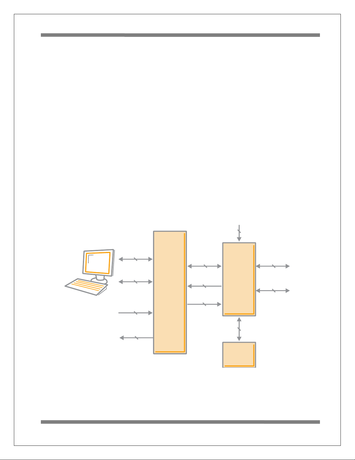
Hardware Block Diagram
MIL-STD-1553
Bus A
MIL-STD-1553
Bus B
Serial Peripheral
Interface
4 Signals
DIP Switches
Status Signals,
Interrupts, Etc.
USB
Debug Port
RS-232 Serial
Console I/O
User
Pushbuttons (3)
Status
LEDs (2)
Control
Signals
64K Byte
Serial
EEPROM
HOLT
HI-6131
ARM
Cortex M3
MCU
Page 5

AN-6131API
5 Holt Integrated Circuits
Hardware Design Overview
Separate schematics and BOM’s documents are included on the Holt CD-ROM.
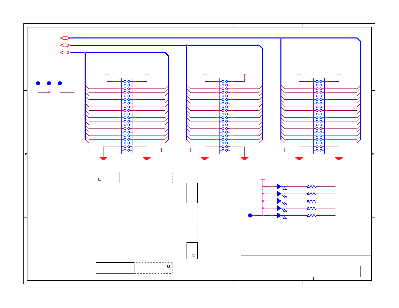
The detachable HI-6131 board can be separated from the provided MCU board for connection to a usersupplied alternate microprocessor or FPGA board. The inter-board headers are located on 0.1” (2.54 mm)
grid for compatibility with generic prototyping boards. All host interface signals go through the inter-board
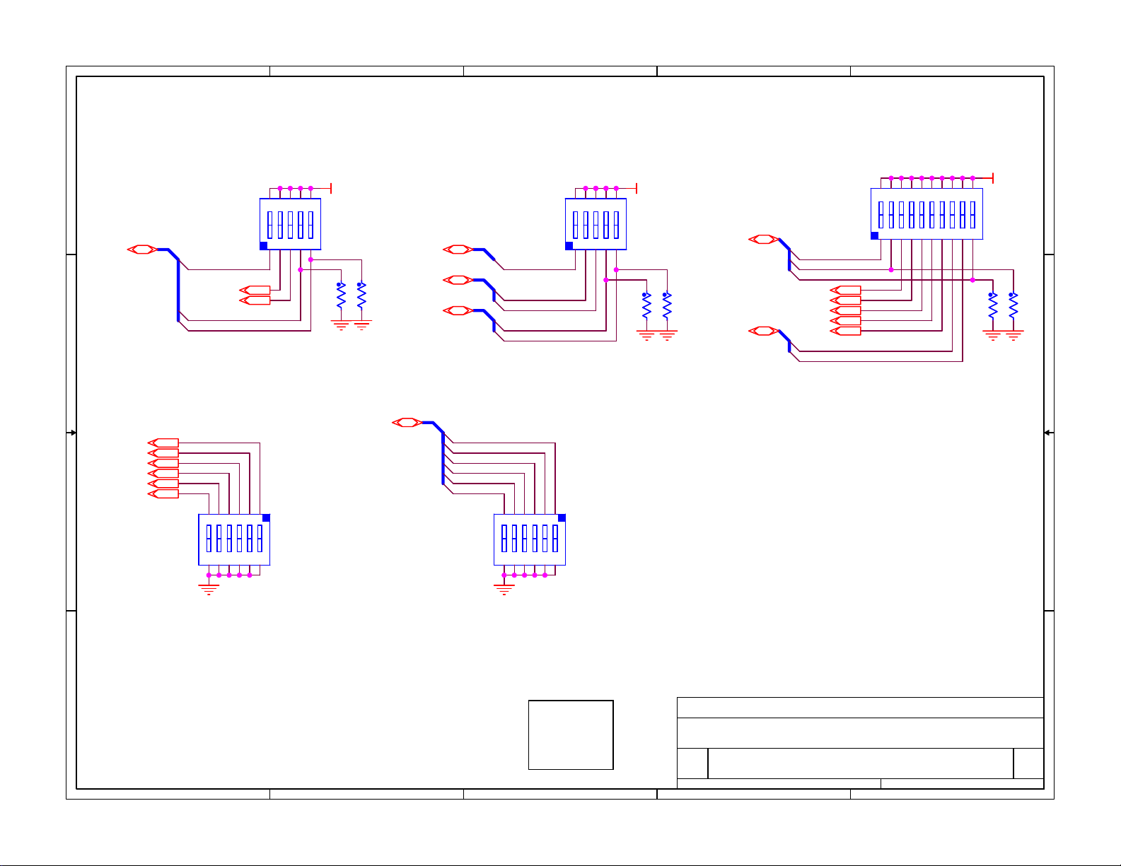
headers. Numerous HI-6131 configuration pins (and the Remote Terminal address setting pins) are
controlled by DIP switches on the upper HI-6131 board; these signals are not available on the inter-board
headers.
The lower ARM Cortex M3 board is based on the flash-programmable Atmel AT91SAM3U-EK
microprocessor. A 4-signal Serial Peripheral Interface (SPI) clocked at 16MHz (20MHz is possible) connects
to the HI-6131. A UART-based serial port provides RS-232 console I/O (optional). An uncommitted USB
2.0 port is available for future expansion. Two pushbuttons are available for software interaction. A RESET
pushbutton resets the ARM microprocessor, which in turn controls the HI-6131 Master Reset signal.
The ARM Cortex M3 board includes “J-Link On Board” debug interface, licensed from www.segger.com,
providing out-of-box readiness without having to buy a costly JTAG debug cable. The kit includes a simple
USB cable for connecting the board’s debug interface to your computer. (For users already owning an
ARM debug interface with ribbon-cable connector, an ARM-standard 2x10 debug connector provides
debug connectivity. In this case, jumper JP2 on the bottom of the lower board should be soldered closed
to disable “J-Link On Board”.)
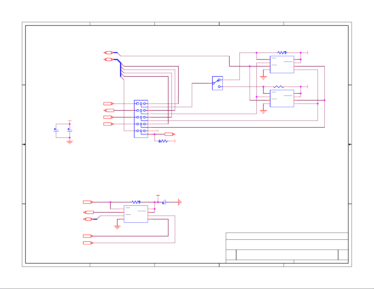
The 64K serial EEPROM is not demonstrated on this kit. For information on the AUTO initialization feature
of the HI-6131 using the EPPROM see document AN-6131.pdf for the non Holt API version of the demo kit
software.
Holt API Host Memory Considerations
Holt API uses C malloc() functions to allocate memory from ARM Cortex M3 internal SRAM for API host
buffers. The total amount of SRAM available on the selected Atmel ARM Cortex M3 MCU is 48K bytes.
This SRAM is shared for all C code static, dynamic variables including the stack and heap. The 48K bytes
are adequate for the demonstrations in this software. User SRAM requirements depend on number of
enabled 1553 terminal modes and buffer size(s) needed for the application.
If more memory is required, choose a processor with more SRAM or augment the processor with external
SRAM. The Holt ADK-6130-2 board is an example that uses the same Atmel ARM Cortex M3 processor
with an additional 256K byte external SRAM memory. See AN-6130-2.pdf for this example. Note: The ADK6130-2 uses a Holt HI-6130 protocol IC with parallel bus interface (not SPI) and the SRAM memory
expansion also uses the MCU external bus interface.
Page 6

AN-6131API
6 Holt Integrated Circuits
There are alternative MCUs with more internal SRAM. For example NXP offers “Kinetis” ARM Cortex M4
microcontrollers with up to 256K bytes internal SRAM. NXP offers the Kinetis ARM Cortex M4 in SPI-only
(as well as SPI and External Bus Interface) configuration. A SPI-only selection could replace the ARM Cortex
M3 on the board we are using here, with up to 256K bytes internal SRAM.
Initial Kit Set Up
The Application Development Kit is pre-programmed to concurrently operate as a Bus Controller, SMT
Bus Monitor and two independent Remote Terminals. Terminal addresses for the two RTs are preset using
DIP switches, before applying power. The two 6-position DIP switches should already be set with these
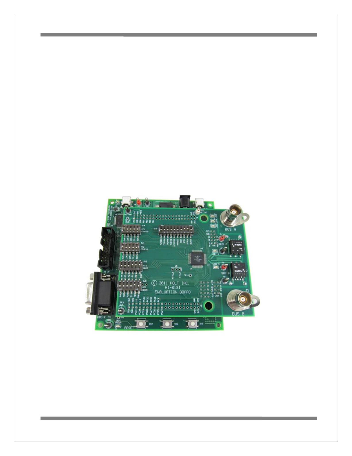
address values, plus odd parity. The RT1 DIP switches should be set to RT address 3 (0-0-0-1-1-parity 1),
RT2 should be set to RT address 1 (0-0-0-0-1-parity 0), to work with the demonstration program utilized
by the preprogrammed Bus Controller message repertoire. The two 6-position DIP switches should
already be set with these address values, plus odd parity and match the board photo on page 2. The user’s
guide, source code and software documentation sometimes refers RT1 as just RT.
1. The PC will need a serial (COM) port and a “terminal emulation” program like TeraTerm. Most
computers no longer have RS232 com ports so will require a serial-to-USB adapter, supplied with
the ADK. Connect this to the computers USB port and the 9 pin connector to the ADK board.
2. If using Windows 2000 or Windows XP, you can use HyperTerminal for terminal emulation. Open
HyperTerminal by clicking Start then All Programs; click the Windows Accessories then
Communications program group. Double-click HyperTerminal to run it. Skip the next paragraph.
If using Vista or Windows 7…
HyperTerminal is not included with these versions of Windows. Install the free open-source
terminal emulation program, TeraTerm 4.71, by running the provided teraterm-4.71.exe installer
program from the Holt CD. Accept the license agreement stating redistribution is permitted
provided that copyright notice is retained. The notice can be displayed from the TeraTerm window
by clicking Help then clicking About TeraTerm. Continuing to install…
Accept the default install destination and click Next.
At the Select Components screen, unselect all options except Additional Plug-in =
TTXResizeMenu and click Next.
Select the installed language, then click Next.
Accept the default Start Menu folder, then click Next.
Select any desired shortcuts, then click Next.
At the Ready to Install screen, click Install.
Page 7

AN-6131API
7 Holt Integrated Circuits
Run the TeraTerm program. At the New Connection screen, select (x)Serial and choose the
selected COM port. Click Setup then Serial Port to open the serial port setup window. Choose
these settings: Baud Rate: 115200, Data: 8 bits, Parity: none, Stop: 1 bit, Flow Control: none.
3. After configuring the Console port, connect the DB-9 serial cable to the PC.
4. Do not connect the included USB debugger cable between the DEBUG port on the lower (MCU)
board and the PC until instructed to, later.
5. To observe bus activity, connect an oscilloscope to the red test points labeled BUS A and BUS B.
The test point labeled ACTIVE is a convenient scope trigger signal that goes high at start of
message and goes low at message completion.
6. If not connected by cable to actual MIL-STD-1553 buses, provide resistive dummy loads for buses
A and B by connecting a 75 Ω 1/2 Watt (or any value between 70-80 Ω) resistor across each pair
of red and black Bus test points. (For this demonstration, half-Watt resistors are adequate
because duty cycle is sufficiently low. When using the on-chip HI-6131 to generate BC messages
directed to on-chip RTs, use external 75 Ω resistor loads. When using a bus coupler to connect to
actual MIL-STD-1553 buses, do not use the 75 Ω dummy load resistors.
7. Set SW8 configuration DIP switches labeled AUTOEN and COPYREQ off (down position). These
switches are not used by this version of the demo program so they can be repurposed by the user.
8. Plug-in the provided 5V DC power supply and connect the cable to the power input jack on the
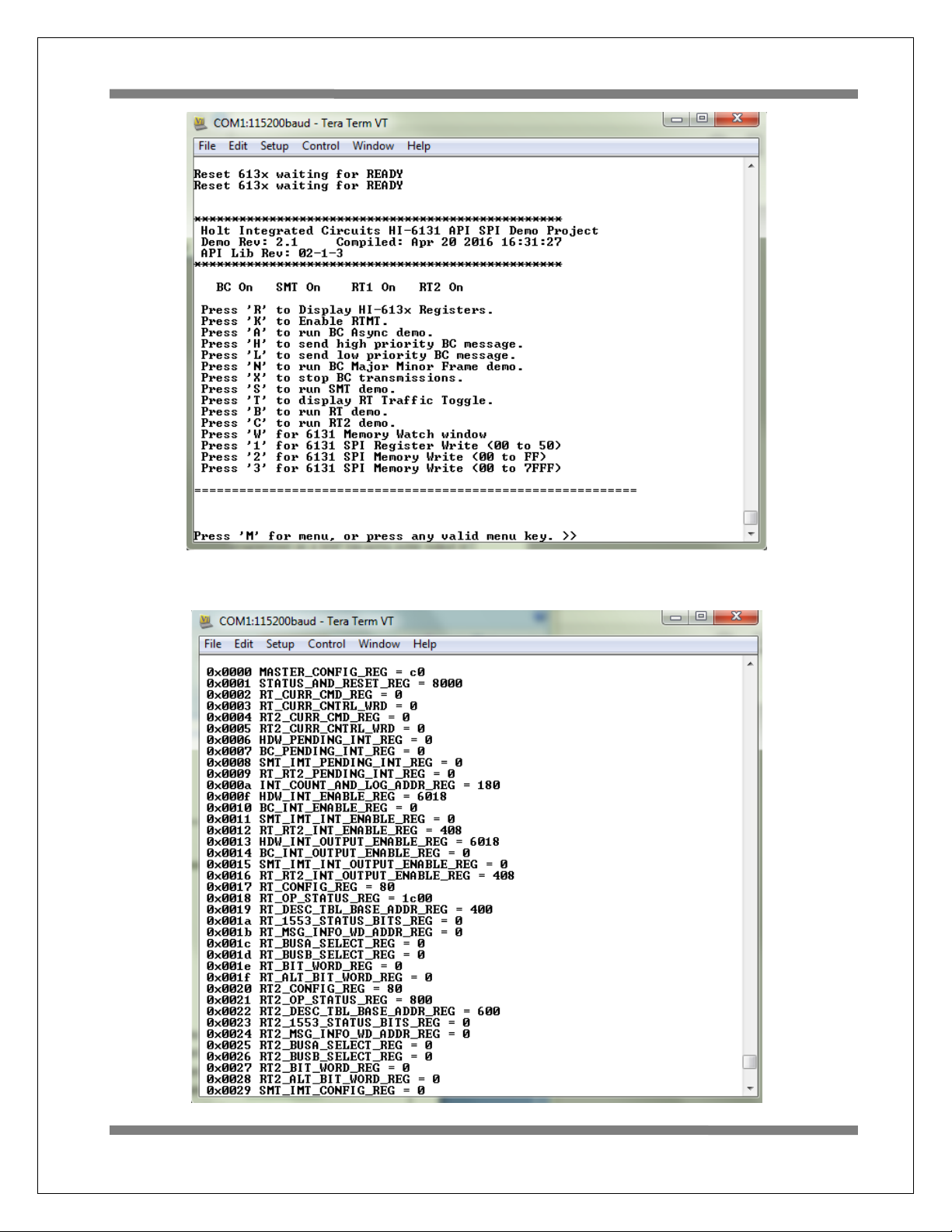
lower circuit board. If TeraTerm is running and configured correctly, the command menu below
should appear in the console window.
9. This menu appears and three green LEDs will flash momentarily whenever the board power is
applied, or when the RESET pushbutton is pressed. After verifying correct TeraTerm
communication with the evaluation board, the terminal set up can be saved by clicking Setup then
Save Setup.
The dates and times shown will differ from the screen captures shown below.
Page 8
AN-6131API
8 Holt Integrated Circuits
Press ‘R’ or ‘r’ to display the HI-613x registers.
Page 9

AN-6131API
9 Holt Integrated Circuits
General Structure of Demo Functions
The Holt API demonstration program is contained in module demos.c. The Holt API runtime library is
contained in the library file “HI-613x API LIB.a” as executable object code. File demos.c
contains the demo initialization API function calls supporting demonstrations executed from the console
menu to initialize the BC, RT,RT2 and monitor terminals. Key presses are detected in console.c
which is called from the main loop in main.c and executes demo functions in demos.c.
Commands ‘A’ and ‘N’ transmit BC commands can be viewed on an oscilloscope and optionally display
the message traffic data on the console using the ‘K’ and ‘T’ command sequence. These demos
demonstrate how Holt API’s are used to generate BC Asynchronous messages, Major/Minor frames, low
priority and high priority messages. View these messages with external MIL-STD-1553 test equipment or
view them with an oscilloscope.
This exercise uses the internal BC to transmit messages, so message traffic data is displayed on the
console. Since the internal BC, RTs and SMT share the same bus pins, the RT’s and SMT monitor
terminals receive the BC messages. If an external BC is already connected to the bus jack though a bus
coupler, it is okay to leave it connected, but disable any external BC transmissions that will conflict with
the on-chip BC transmissions.
For the following demonstrations all four terminals in the HI-6131 API demo program are enabled and
initialized by console commands.
BC and RT MT Mode.
This demonstrates BC, RT and MT all together and displays the traffic data on the console.
1. Press command ‘B’ to enable the RT.
2. Press command ‘K’ to enable the RTMT demo.
3. Press command ‘T’ (or spacebar) to display RT traffic on the console. Command ‘T’ toggles on
and off alternately to enable or disable the RT traffic shown on the console. Using the ‘T’
command relies on prior execution of command ‘K’.
4. Press command ‘A’ to start the BC transmitting messages.
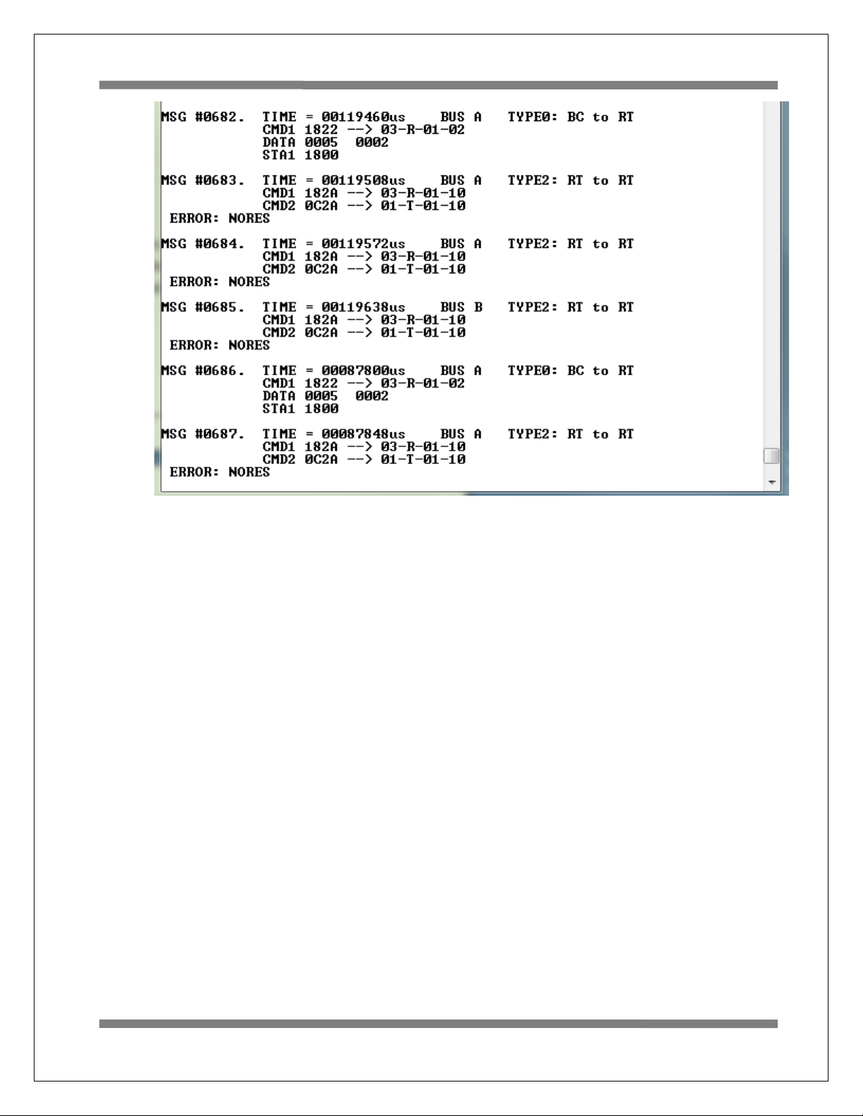
Messages will display rapidly on the screen, Press the space bar to stop the console output. The
console should freeze and look similar to the screen below. Press space bar again to restart the
console output. Using the space bar does not stop BC transmission or prevent RT or MT message
reception; it only stops console output.
Page 10
AN-6131API
10 Holt Integrated Circuits
Some of the BC commands are RT to RT. The BC commands to RT3 only shows no errors but RT
to RT commands to RT1 and RT3 will show “ ERROR: NORES” (no response) since there’s no RT
at address 1.
To see these same messages without the “ERROR:NORES” enable RT2 by pressing the ‘C’
command and repeat the messages. RT2 will now receive and acknowledge the messages to RT2
which is set to RT address 1 by DIP switches.
The Bus A green LED flashes rapidly (but appears continuously lit) with this demo.
5. BC Low Priority Asynchronous Message Insertion
Command ‘L’ inserts a low priority message into the scheduled BC message list. Low priority Inserted
messages occur upon completion of any BC minor frame in-process when insertion is requested.
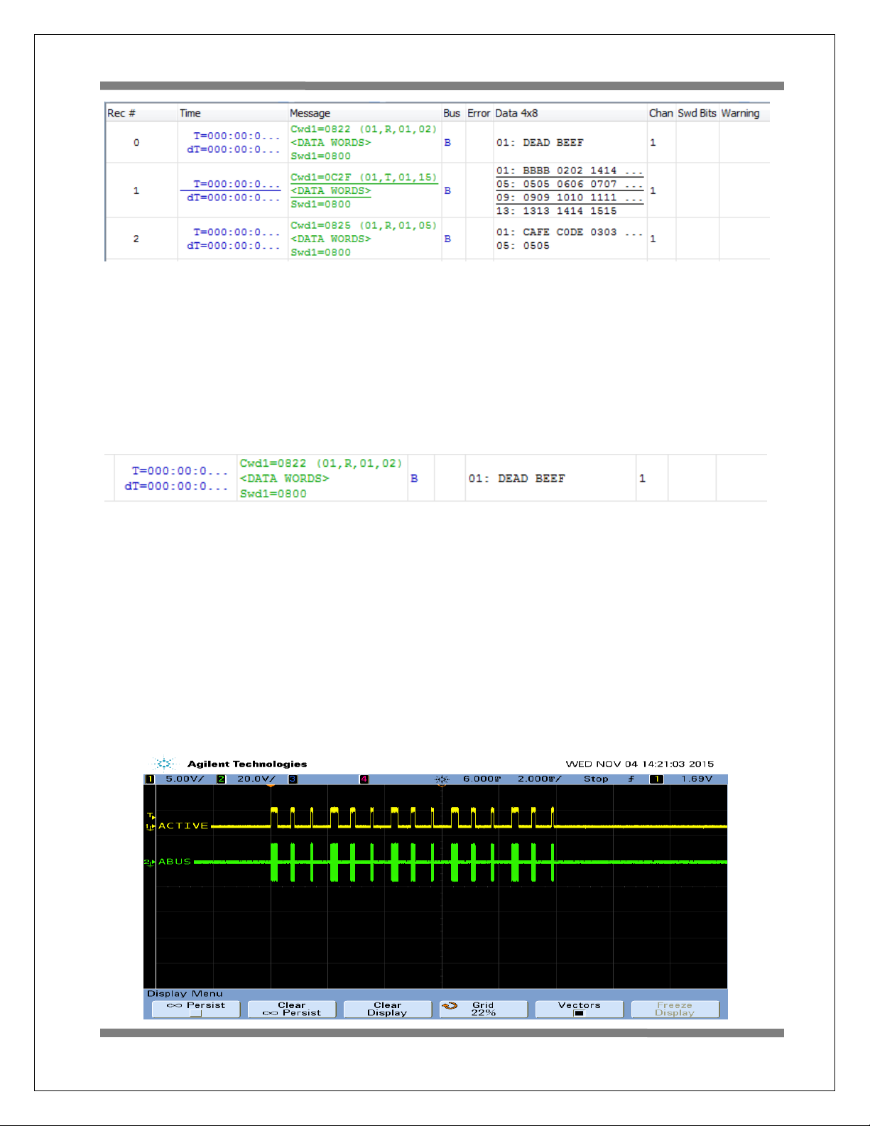
First, enable the RT by pressing ‘B’ then Press ‘A’ to enable the BC transmission. Press ‘L’ to transmit
three extra messages on Bus B. Bus B is used to make it easier to see on the scope and the Bus B LED
should flash. If the RT is not enabled, retry messages appear on Bus B; this makes it difficult to see
the three inserted messages. This will only work once after a power up or RESET.
The screen shot of these three messages are shown below captured by a Ballard USB UA1133 tester.
Page 11
AN-6131API
11 Holt Integrated Circuits
6. BC High Priority Asynchronous Message Insertion.
Follow the same steps as the previous BC low priority message example but this time Press ‘H’ to
insert a single high priority message. This command is repeatable and the Bus B LED will flash with
each command. Inserted High Priority messages occur upon completion of any in-process message
when insertion is requested.
7. Command ‘E’ Enumerate Card is reserved for future use.
8. From a RESET, if the BC is started before enabling the ‘K’ and ‘T’ sequence to display message
traffic, the first message may contain an error. This is normal; this occurs because the RT and MT
are enabled midstream of a message in progress.
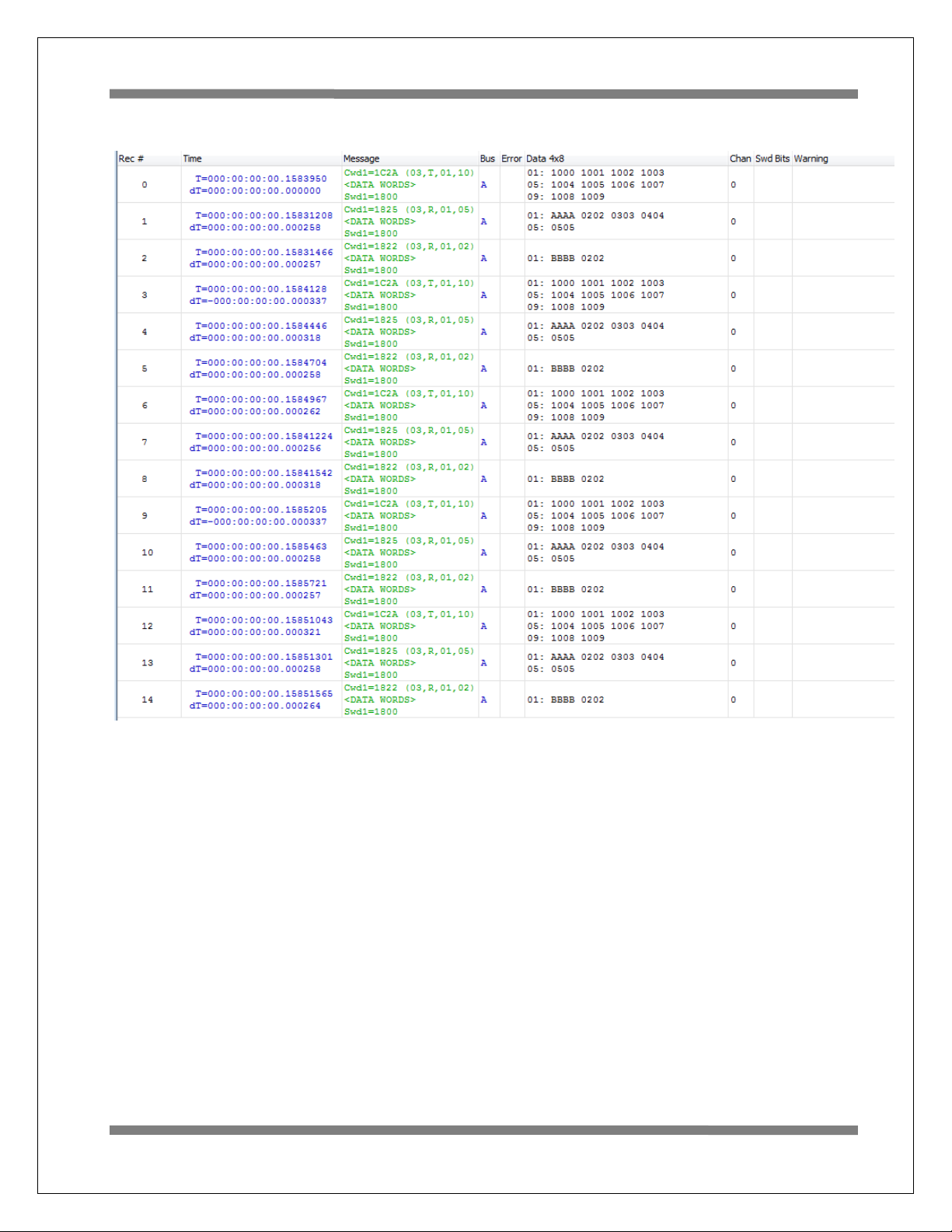
9. The ‘N’ command transmits fifteen commands to RT address 3. Press ‘B’ to enable the RT.
Press ‘N’ to execute the BC transmissions (15 messages are transmitted) which will appear on the
bus as shown below. To optionally see the message traffic on the console, enable the RT message
traffic by pressing ‘T’ if it hasn’t already been enabled.
Page 12
AN-6131API
12 Holt Integrated Circuits
Command ‘N’ (15 message) Traffic capture using a Ballard USB 1553 monitor.
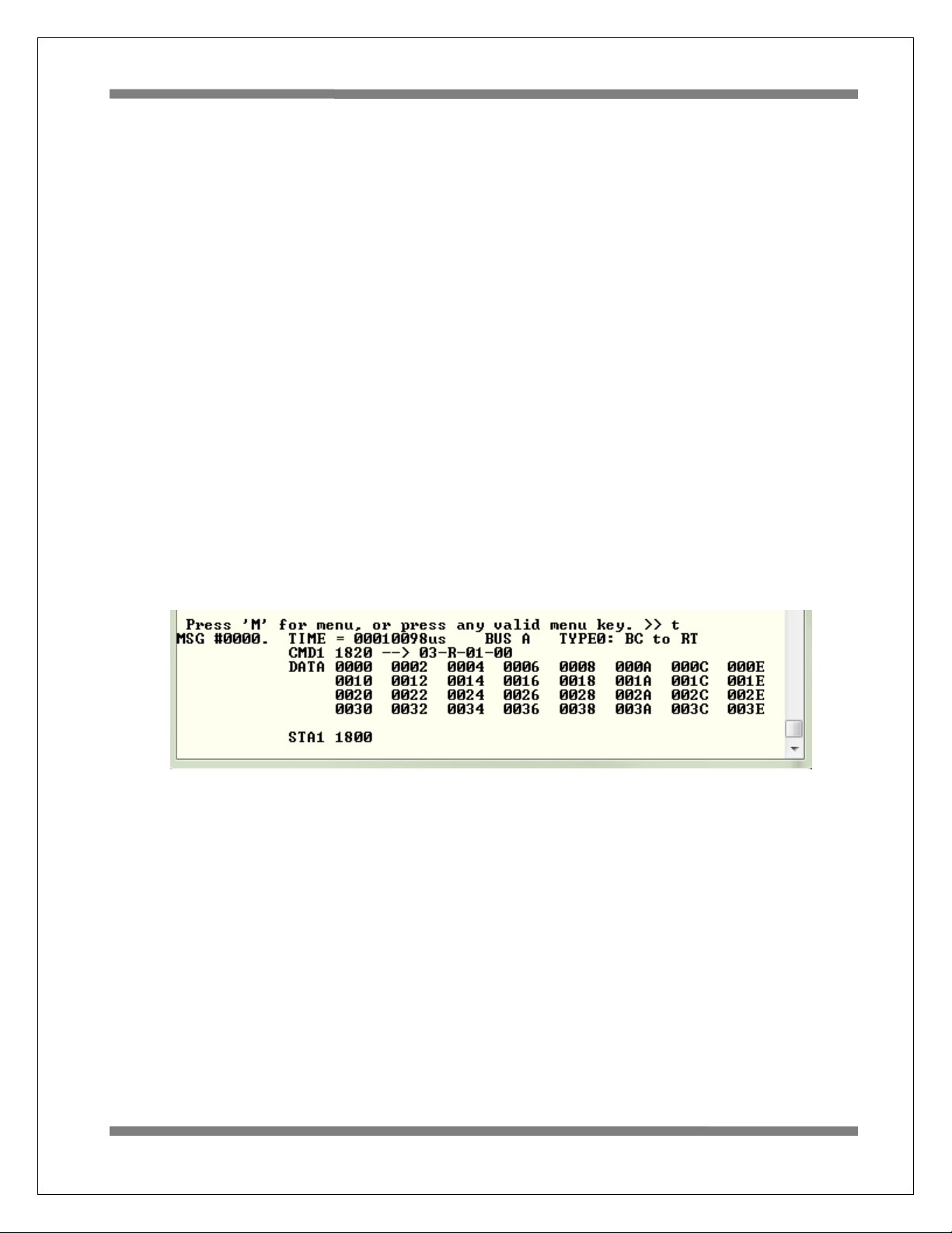
When a BC message is transmitted to a RT that is not enabled, “RT no response” (NORES) error is
indicated.
MSG #0170. TIME = 00086918us BUS A TYPE2: RT to RT
CMD1 182A --> 03-R-01-10
CMD2 0C2A --> 01-T-01-10
ERROR: NORES
Page 13
AN-6131API
13 Holt Integrated Circuits
RT Mode using external BC
Using an external BC tester (such as Ballard USB 1553) to transmit messages to the demo
board.
1. When an external BC is connected using conventional 1553 buses, use cables to connect the
demo board circular tri-axial bus jacks to bus coupler ports on the A and B bus networks. In this
case any external bus load 70 Ω resistors should be disconnected.
If bus couplers are not readily available, bench testing can be done by connecting external
dummy bus load 70 Ω resistors and connecting BC tester cables directly to the demo board triaxial jacks for buses A and B.
2. Press the RESET button and then Press ‘B’ to enable the RT (RT1) then Press ‘K’ and ‘T’ to
activate the RT traffic on the console. Compose a BC to RT message with SA=1 and 32 data
words similar to the message shown below using external BC tester equipment.
3. The console should show the message transmitted by the BC, after the transaction.
4. When transmitting repeating messages at a high rate typical of MIL-STD 1553, the RT Traffic
shown on the console may not keep pace due to limitations of the console 115,200 baud rate
and the prolific use of slow-to-execute printf function calls in the C program’s console user
interface. Depending on the message content and repetition rate, some messages may not show
on the console. All messages are transacted properly and captured by enabled RT and MT, some
messages simply will not be shown on the console.
Page 14
AN-6131API
14 Holt Integrated Circuits
MT Mode
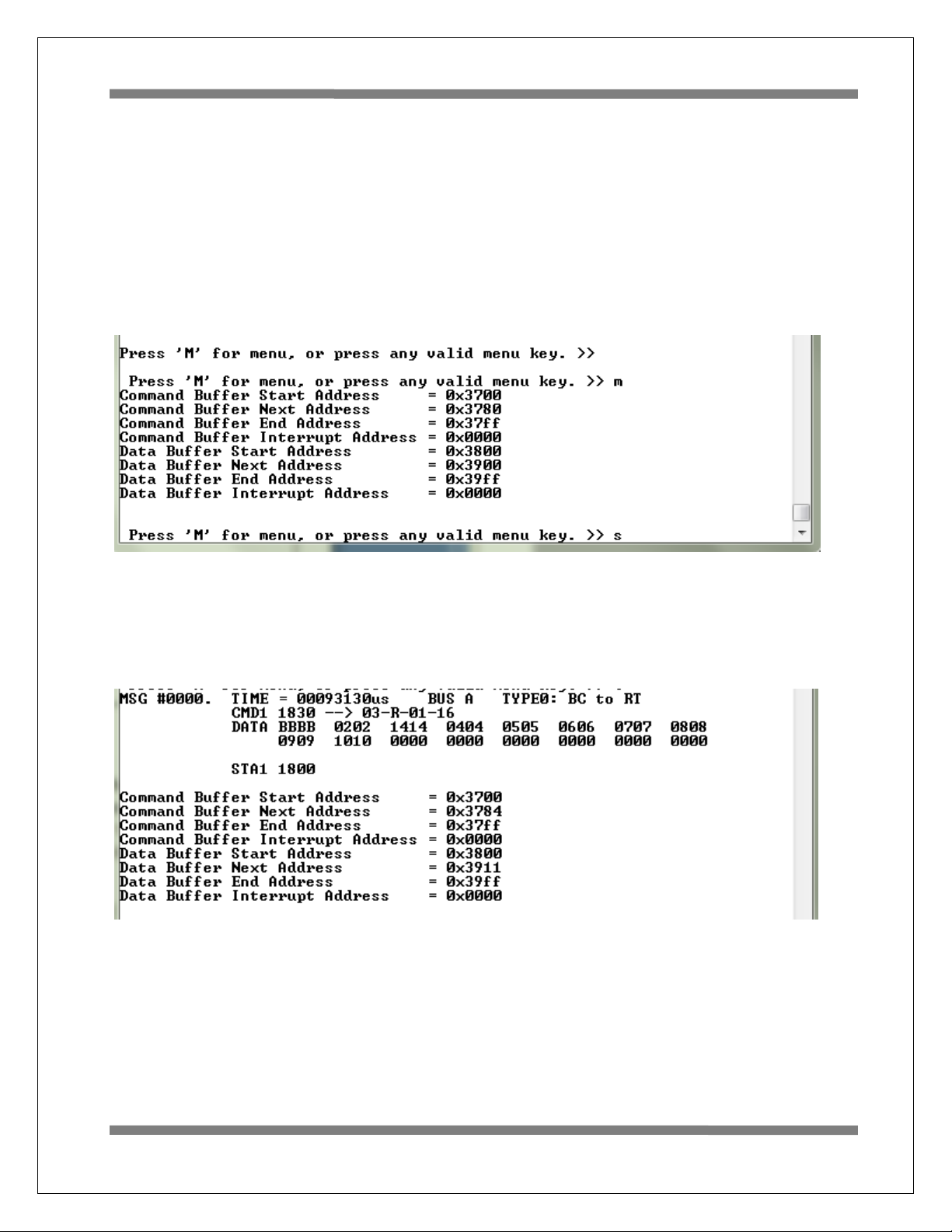
Press ‘S’ to enable SMT simple monitor. No other terminal is required; ‘S’ can be used after board reset.
A list of addresses shows the Command Stack and Data Stack buffer start address and end address. After
sending some messages to the monitor use this command to display the addresses and use the Memory
Watch window to view the Command and Data in memory. The SMT is also initialized with the ‘K’
command that provides message details. The ‘T’ RT Traffic feature toggles display of formatted RT
message data on the console. The data shown below is the default values after a board reset.
After one message transmitted by an external BC as shown will produce the following results.
Page 15

AN-6131API
15 Holt Integrated Circuits
Getting Started with the Holt API demo software project and installing
IAR Systems Embedded Workbench for ARM Compiler
1. Installed IAR Systems Embedded Workbench for ARM (EWARM ) compiler is required BEFORE
adding the Holt demo projects, so all Atmel board library files and the demo project folder are
created in the proper location. Follow the “Holt HI-6131 API Demo Project Installation Guide”
found in the Project folder on the Holt CD-ROM. Before proceeding to the next steps IAR must
be installed and the two Holt project folders must be in the proper folder locations, according to
that guide. Instructions beyond this point assume you have completed the above installation
tasks.
2. Launch IAR Embedded Workbench from the Windows Start menu. A blank screen should appear.
Open the Holt HI-6131 API Demo Project from the IAR File pull-down menu, click on
File/Open/Workspace and navigate to the project folder location and select “HI-6131 API
Demo.eww” and click the Open button.
3. An IAR Workspace window should appear on the left side as shown below. If the Workspace
directory pane is missing, select “Workspace” from the View pull-down menu. Make any
window adjustments or open any of the folder groups to view included files to suit your
preferences.
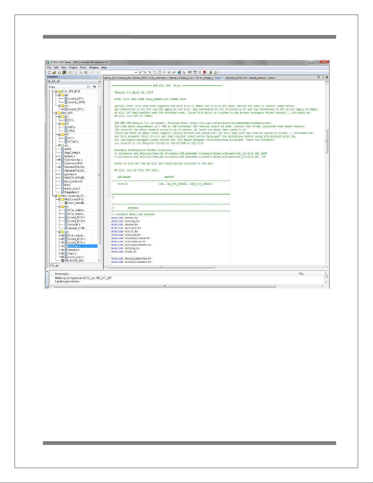
4. Double click the main.c file, it should appear in the text editor pane, similar to the screen
capture shown on the next page.
5. The first time a project is unzipped and installed in the appropriated folder a Rebuild All should
be performed (from Project pull down menu).
6. IAR getting started, project management and other guides are available from the IAR
Workbench Help pull down menu.
Mode Holt Project Configurations
IAR project configurations are used to reconfigure the demo software using preprocessor macros.
Configurations are selectable from the Workspace pull-down menu using macros defined in the project
options C/C++ preprocessor tab. The three macros IAR, IAR_SPI_ENABLE and IAR_HI-6131_ENABLE
control which sections of code are compiled for the demo project. Other macros are used to enable BC,
RT or SMT sections of code. Holt uses a common code base for multiple projects. This means there are
functions not used in this project but are left in the C and H files. The IAR compiler uses the macros to
select sections of code to build and link. Some references to HI-6130 or HI-6138 MAMBA™ are to be
expected. In some cases some functions are simply not used or macros are used inside a function to select
appropriate code.
Page 16
AN-6131API
16 Holt Integrated Circuits
Main Project demo screen (move and size the windows according to preference):
Page 17
AN-6131API
17 Holt Integrated Circuits
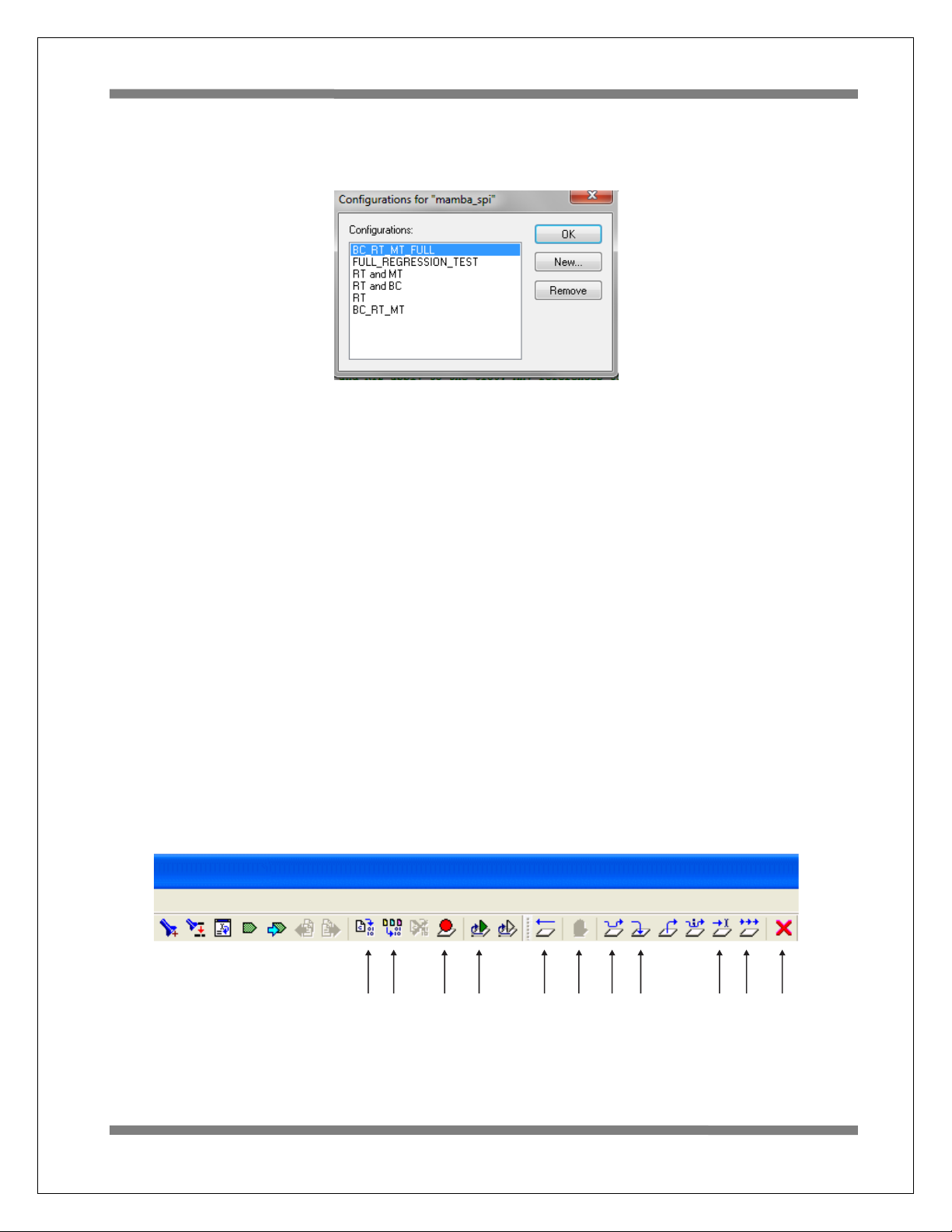
The configuration list may vary slightly from the list shown.
Project configurations with “FULL” required the Holt API library source code. The API library source code
is not provided in the standard ADK. The full API source code is available with a signed Holt software
license agreement (SLA). The standard ADK demos are fully functional otherwise, and API projects can
be built without the API C source code. Contact Holt sales for the SLA for the optional API C source code.
The “FULL REGRESSION_TEST” is for Holt testing only and can be deleted by the user.
A simple way to create a new configuration is to select Project/Edit Configurations and then select New.
The dialog box will allow a new configuration based on an existing configuration with a new
configuration name. Select the new configuration and edit the preprocessor labels as desired then save
the new configuration. The new configuration will now appear in the pull down menu. Project file
613x_initialization.h configures other critical project settings, including the time tag
resolution and console I/O on-off.
The IAR embedded workspace provides may of the commonly used tasks as short-cut buttons on the top
as shown.
Stop
Debug
Toggle
Brkpoint
Restart
Make
Reset
Break
Step
Into
Run to
Cursor
Go
Step
Over
Compile
IMPORTANT EMBEDDED WORKBENCH BUTTONS
Page 18

AN-6131API
18 Holt Integrated Circuits
Project File List with Selected Descriptions
Most of the function names are self-explanatory, some functions retain the names from the original 61302 or MAMBA™ (HI-6138) project they were written for, don’t worry about this they work fine with the HI6131 API demo.
device_SPI.h
Macro definitions for register addressing.
board_SPI.c, board_SPI.h
SPI configuration, SPI read/write and Memory watch functions. SPI frequency selection.
613x_initialization.h
Definitions for important configuration settings.
613x_Interrupts.h
Provides interrupt related prototypes for API use.
main.c
The primary program entry portal, main()demonstrates initialization sequence used of enabled
terminals. After initialization is complete, function calls demonstrate powerful addressing
methods for all RAM structures used by the enabled terminal modes. Demo initialization and
execution uses Holt high-level API in this demo kit.
board_613x.c, board_613x.h
Contains ARM MCU SPI i/o definitions and macro definitions for
SPI commands
SPIopcode(opcode) ;
Write_6131LowReg(reg_number, data, irq_mgmt) ;
Read_6131LowReg(reg_number, irq_mgmt) ;
Write_6131_1word(data, irq_mgmt) ;
Read_6131_1word(irq_mgmt) ;
Write_6131(write_data[], inc_pointer_first, irq_mgmt) ;
Read_6131(number_of_words, irq_mgmt) ;
Write_6131_Buffer(write_data[], inc_pointer_first, irq_mgmt) ;
Read_6131_Buffer(number_of_words, inc_pointer_first, irq_mgmt) ;
Read_Current_Control_Word(rt_num, irq_mgmt) ;
getMAPaddr() ;
enaMAP(map_num) ;
Read_Current_Control_Word(rt_num, irq_mgmt);
Read_RT1_Control_Word(txrx, samc, number, irq_mgmt);
Read_RT2_Control_Word(txrx, samc, number, irq_mgmt);
ReadWord_Adv4(irq_mgmt) ;
Page 19

AN-6131API
19 Holt Integrated Circuits
Read_Last_Interrupt(irq_mgmt) ;
Fill_6131RAM_Offset() ;
Fill_6131RAM(addr, num_words, fill_value) ;
Memory_watch(address);
Configure_ARM_MCU_SPI();
Spi_register_write();
Spi_memory_write_ff();
Spi_memory_write_1fff();
board_613x.c
ConfigureGpio(); initializes ARM MCU general purpose I/O
reset_613x();
init_timer();
Delay_us(num_us);
Delay_ms(num_ms);
Delay_x100ms(num);
Flash_Red_LED();
Flash_Green_LED();
board_613x.h;
Contains ARM MCU i/o definitions controlled by macros. The SPI pins
are common between MAMBA™ and HI-6131 since both use a SPI
interface.
BC.h
BC.h has macros, C structures and prototypes for API use.
MT.h
MT.h has macros, C structures and prototypes for API use.
RT.h, RTMT.h
Has macros, C structures and prototypes for API use.
console.c
Console functions used by all terminal modes:
ConfigureUsart1();
Show_menu();
chk_key_input();
list_all_regs();
Console functions used by Bus Controller (BC) mode:
bcAsync();
MajorMinorframe();
Page 20

AN-6131API
20 Holt Integrated Circuits
Console functions used by Remote Terminal RT:
RTDemo();
Rt_mt();
Console functions used by SMT or IMT bus monitor modes:
SMTDemo();
Primitive console functions that "printf" redundant char strings to reduce program size:
print_null(), print_sp1sp(),print_b1sp(), print_b0sp();
print_dddn(), print_dd0n(), print_dd1n();
print_menuprompt(), print_line();
Console function called by the Memory_watch() function
Manual SPI write utilities
ascii2int();
demos.c
Provides all demo functions that are called by the console menu.
DisplayDecodedMsg(); used to display 1553 formatted data to the
console when the ‘T’ command is used.
displayRTTraffic(); called from main; calls DisplayDecodedMsg()
board_lowlevel.c
This is an Atmel board file that changes the flash memory wait
states to 3WS.
Flash_MAMBA.icf - Project Linker File SAME one used for MAMBA™ for
this HI-6131 API demo project.
HI-613x API LIB.a – Precompiled Holt API library.
Holt API Library files
The standard API kit does not include the Holt API source files
although the API header files are included and grouped in the
workspace Holt_API/src sub-folder.
Page 21
AN-6131API
21 Holt Integrated Circuits
HI-6131 SPI Interface
The HI-6131 was designed for compatibility with microcontrollers having a Serial Peripheral Interface (SPI).
RAM and register locations are written or read with the help of 8-bit SPI commands. Most read or write
operations use one of four Memory Address Pointers (MAPs) to designate the address of the next location
accessed. To speed up a multiword transfers, the enabled Memory Address Pointer automatically
increments to the next address after each read or write is performed. Register addresses 0-15 decimal
can be read directly, without using a memory address pointer. Register addresses 0-63 decimal can be
written directly without using a memory address pointer.
When debugging, a memory watch utility may be helpful for observing register or RAM values. However
SPI-accessed memory cannot be viewed from an IAR Embedded Workbench debug memory display
window. The demonstration program provides memory watch capability via SPI, by using a C function
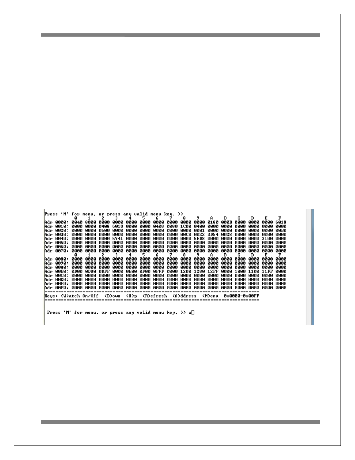
called Memory_watch(). This function call only works when Console I/O is enabled. It displays 256
consecutive register or RAM values, starting with the provided memory address parameter. The entire
memory address space 0 to 0x7FFF is accessible in 256 word increments. The demonstration program
polls for keyboard input, and must be running. When the console menu “W” command is entered, the
memory address space from 0x0000 to 0x00FF is displayed:
Be mindful that each displayed location is rescanned when Memory_watch( ) executes. Some register or
RAM structure bits automatically reset after read occurs. This includes bits in the Pending Interrupt
registers, and DBAC Data Block Accessed bits for RT Descriptor Table Control Words in RAM. For these,
the Memory Watch window reflects the value in effect when the function executed.
The console I/O option using TeraTerm includes several menu options that read and display Pending
Interrupt register status. Remember that Pending Interrupt bits automatically reset after read occurs. For
these registers, the Memory Watch window reflects the value in effect when execution stopped.
Page 22

AN-6131API
22 Holt Integrated Circuits
The HI-6131ADK demonstration program is set up with Bus Controller, Remote Terminal 1, Remote
Terminal 2 and Simple Monitor all enabled. Enabling or disabling any of these terminal functions is a twostep process: the software configuration (controlled C/C++ preprocessor macros) must match the
hardware configuration DIP switches (BCENA, RT1ENA, RT2ENA and MTRUN) or a software error trap
occurs. The preprocessor macros settings are set in the Project pull-down menu/Options/CC++/Preprocessor tab.
The sub-menu at the bottom of the screen lists available Memory Watch options. Pressing ”D” (DOWN
command) changes the displayed address range to 0x0100-0x01FF. Pressing ”U” (UP command) from the
above screen wraps around the device address space, changing the displayed address range to 0x1F00-
0x1FFF. Repeating UP or DOWN commands moves through the address range. Pressing “R” refreshes the
currently selected address range, while pressing “A” (ADDRESS command) allows you to enter four
hexadecimal characters to select any Memory Watch start address. Pressing “W” (WATCH) or “M” (MENU)
toggles off Memory Watch display, restoring the menu shown on page 5.
For advanced users, other utilities available on the console (commands ‘1’, ‘2’ and ‘3) menu are also
supplied for SPI writing to registers and memory addresses.
Page 23

AN-6131API
23 Holt Integrated Circuits
Summary
With just 4 host interface signals for accessing RAM or registers, the HI-6131 SPI interface simplifies MILSTD-1553 terminal hardware design and saves considerable board space over a similar 16-bit parallel
address and data bus interface.
The Holt 1553 API Runtime Library simplifies HI-6131 programming by providing high level C function calls
that greatly accelerate project development.
Page 24

Bill of Materials HI-6131 Evaluation Board, To
p
m
p
n
e
N
Revised: July 19, 2011
Ite
Qty
Descri
tio
Referenc
DigiKey Mfr P/
1 1 PCB, Bare, Eval Board N/A -------- -------2 9 Capacitor, Ceramic 0.1uF 20%
50V Z5U 0805
C1,C2,C5,
C6,C7,C8,
399-1176-1-ND Kemet C0805C104M5UACTU
C9,C10,C11
3 1 Capacitor, Ceramic 4.7uF 10%
C5 399-3134-1-ND Kemet C0805C475K9PACTU
6.3V X5R 0805
4 1 Capacitor 68uF 10% 6.3V
C3 495-1507-1-ND Kemet B45197A1686K309
Tantalum 400 mOhm SMD EIA
6032-28
5 2 Connector 3-Lug Concentric
Triax Bayonet Jack, Panel
J1,J2 MilesTek 10-06570 Trompeter Electronics BJ77
Use 0.469" Round Hole
Front Mount TRB (BJ77)
6 1 Header, Male 2x10 0.1" Pitch,
J3 S2012E-10-ND Sullins
0.230" Pins, 0.120" Tails
7 1 Header, Male 2x7 0.1" Pitch,
J4 S2012E-07-ND Sullins
0.230" Pins, 0.120" Tails
8 1 Header, Male 2x4 0.1" Pitch,
J5A S2012E-04-ND Sullins
0.230" Pins, 0.120" Tails
9 1 Header, Male 2x5 0.1" Pitch,
J5B S2012E-05-ND Sullins
0.230" Pins, 0.120" Tails
10 ------ Header, 1x3, 0.1" pitch J6 DO NOT STUFF -------11 ------ Header, 1x8, 0.1" pitch J7 DO NOT STUFF -------12 1 Header, 5x3, 0.1" pitch JP1 Samtec Samtec TSW-105-07-T-T
13 5 Jumper, shorting, w/ grip, 0.1" JP1 S9341-ND Sullins NPC02SXON-RC
14 Solder Jumper JP2,JP3 DO NOT SOLDER -------15 1 LED Yellow 0805 LED5 160-1175-1-ND Lite On LTST-C170YKT
16 3 LED Green 0805 LED1 - LED3 160-1179-1-ND LiteOn LTST-C170GKT
17 1 LED Red 0805 LED4 160-1176-1-ND LiteOn LTST-C170CKT
18 1 Osc, 50.00MHz 25ppm 3.3V
OSC1 CTX328LVCT-ND CTX CB3LV-3I-64M0000-T
SMD 5mm x 7mm
19 5 Resistor, 150 5% 1/8W 0805 R8,R9,R10,
P150ACT-ND Any
R11,R12
20 1 Resistor, 1.0K 5% 1/8W 0805 R1 P1.0KACT-ND Any
21 1 Resistor, 2.2K 5% 1/8W 0805 R17 P2.2KACT-ND Any
22 2 Resistor, 10K 5% 1/8W 0805 R30,R31 P10KACT-ND Any
23 6 Resistor, 47K 5% 1/8W 0805 R13,R14,R15
P47KACT-ND Any
R16,R18,R19
24 2 DIP Switch 5-Position SMD SW1,SW4 CT2195LPST-ND CTS 219-5LPST
25 2 DIP Switch 6-Position SMD SW5,SW6 CT2196LPST-ND CTS 219-6LPST
26 1 DIP Switch 10-Position SMD SW8 CT21910LPST-ND CTS 219-10LPST
27 1 Slide Switch SPDT SMD SW2 563-1022-1-ND Copal CJS-1200TB
28 2 Transformer MIL-STD-1553
Single, 1:2.50, PM-DB2791S
T1,T2 Holt PM-DB2791S Premier Magnetics
PM-DB2791S
29 ------ Test Point, pad w/ plated hole TP1,TP9 ------ -------30 2 Test Point, Red Insulator,
TP4,TP6 5010K-ND Keystone 5010
0.062" hole
31 3 Test Point, Black Insulator,
0.062" hole
32 1 Test Point, White Insulator,
TP2,TP3,TP5,
5011K-KD Keystone 5011
TP7
TP8 5012K-KD Keystone 5012
0.062" hole
33 1 IC HI-6131 Holt 64-PQFP U1 ------ -------34 2 IC, Serial EEPROM 512Kbit
U2, U3 25LC512T-I/SNCT-ND Microchip 25LC512T-I/SN
20MHz SPI 8-SOIC, Microchip
Page 25
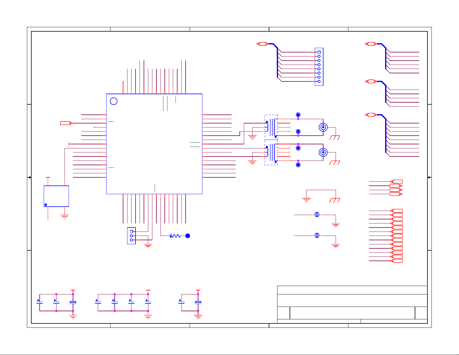
5
D D
TXINHA
TXINHB
U1
U1
62
63
64
NC
BCTRG
RAMEDC
OSC1
OSC1
50.0MHz
50.0MHz
OUT
3V3
MCLK
GND
RT1A0
RT1A1
RT1A2
nMR
RT1A3
RT1A4
nCE
MOSI
SCK
MISO
nCE
C C
3V3
3V3
4
3
VCC
1
2
3
4
5
6
7
8
9
10
11
12
13
14
15
16
BCTRIG
RAMEDC
CE
MODE
SI
SCK
SO
VDD
MCLK
GND
RT1A0
RT1A1
RT1A2
MR
RT1A3
RT1A4
TXINHB
RT1ENA17RT1APAR18MISO19MOSI20VDD21GND22TTCLK23MTTCLK24ECS25EECOPY
OE1GD
2
B B
EMISO
RT1AP
RT1ENA
J6
J6
Header 1x3
Header 1x3
AUTOEN
61
TXINHA
AUTOEN
EMOSI
1
2
3
3V3
60
VDD
3V3
4
GND
RT1SSF
ACTIVE
READY
PKTRDY
56
59
57
58
55
GND
READY
ACTIVE
RT1SSF
HI-6131 PQFP
HI-6131 PQFP
26
nECS
MTTCLK
TTCLK
EECOPY
GND
3V3
ACKIRQ
nRT1MC8
nRT2MC8
nIRQ
51
53
54
52
50
IRQ
ACKIRQ
RT1MC8
RT2MC8
MTPKRDY
ESCLK27MTRUN28RT2SSF29RT2LOCK30RTAPAR31RT2A4
ESCK
MTRUN
RT2LOCK
RT2SSF
RT2AP
R11KR1
1K
GND
49
VDD
GND
BENDI
TEST
RT1LOCK
MTSTOFF
BCENA
BUSA
VDD
BUSA
BUSB
VDD
BUSB
RT2ENA
RT2A0
RT2A1
RT2A2
RT2A3
32
RT2A4
COMP TEST PIN
IS MUXED WITH
EECOPY PIN
TP1
TP1
EECOPY/COMP
EECOPY/COMP
3
TEST BUS, MULTI-FUNCTION
T0 RT2A0
T1 RT2A1
T2 RT2A2
T3 RT2A3
T4 RT2A4
T5 RT2AP
T6 RT2LOCK
T7 RT2SSF
T1
48
47
46
45
44
43
42
41
40
39
38
37
36
35
34
33
BENDI
TEST
RT1LOCK
MTSTOFF
BCENA
BUSA
3V3
nBUSA
nBUSB
3V3
BUSB
RT2ENA
RT2A0
RT2A1
RT2A2
RT2A3
T1
PM-DB2791S
PM-DB2791S
1
2
3
1
2
3
T2
T2
PM-DB2791S
PM-DB2791S
8
7
6
5
4
8
7
6
5
4
TP4TP4
TP5TP5
TP6TP6
TP7TP7
nABUS
nBBUS
2
J7
J7
1
2
3
4
5
6
7
8
Header 1x8
Header 1x8
RED
ABUS
BLK
nABUS
BBUS
RED
nBBUS
BLK
TRANSFORMER
COUPLED BUS
JP2
JP2
Solder Jumper
Solder Jumper
JP3
JP3
Solder Jumper
Solder Jumper
1
3
2
1
3
2
J1
BJ77J1BJ77
J2
BJ77J2BJ77
PA[31:0]T[7:0]
PB[31:0]
PC[31:0]
1
SIGNALS SHARED
WITH MCU
PA0 nRT1MC8
PA1 nRT2MC8
PA13 MISO
PA14 MOSI
PA15 SCK
PA16 nPCS0
PB0 PKTRDY
PB1 nIRQ
PB4 AUTOEN
PB2 READY
BENDIPB16
PC11 RT1ENA
PC10 ACKIRQ
PC9 ACTIVE
PC24 EECOPY
PC25 nMR
PC26 RT2ENA
PC27 MTRUN
PC28 BCENA
PC29 BCTRG
SERIAL EEPROM SIGNALS
EMISO
EMOSI
ESCK
nECS
EMISO
EMOSI
ESCK
nECS
DIP SWITCH SIGNALS
RT1A0
RT1A1
RT1A2
RT1A3
RT1A4
RT1AP
RT1LOCK
RT1SSF
TXINHA
TXINHB
TEST
RAMEDC
MTSTOFF
RT1A0
RT1A1
RT1A2
RT1A3
RT1A4
RT1AP
RT1LOCK
RT1SSF
TXINHA
TXINHB
TEST
RAMEDC
MTSTOFF
HI-6131 PQFP & 1553 BUS
HOLT INTEGRATED CIRCUITS, Mission Viejo, CA, USA
Title
Title
Title
HI-6131 EVAL PCB (Use With Std ARM CM3 Lower PCB)
HI-6131 EVAL PCB (Use With Std ARM CM3 Lower PCB)
HI-6131 EVAL PCB (Use With Std ARM CM3 Lower PCB)
Size Document Number Rev
Size Document Number Rev
Size Document Number Rev
A
A
A
6131 EVAL TOP.DSN A
6131 EVAL TOP.DSN A
6131 EVAL TOP.DSN A
Date: Sheet
Date: Sheet
Date: Sheet
2
14Thursday, October 06, 2011
14Thursday, October 06, 2011
14Thursday, October 06, 2011
of
of
of
1
C9
100nFC9100nF
DECOUPLING
OSC1
C4
100nFC4100nF
3V3
+
+
C5
C5
4.7uF
4.7uF
3
DECOUPLING
U1 PINS 39, 42
A A
+
+
C3
C2
100nFC2100nF
C3
68uF
68uF
5
C1
100nFC1100nF
DECOUPLING
U1 PINS 8, 21, 50, 60
C7
C6
100nFC7100nF
100nFC6100nF
C8
100nFC8100nF
3V33V3
4
Page 26
5
4
3
2
1
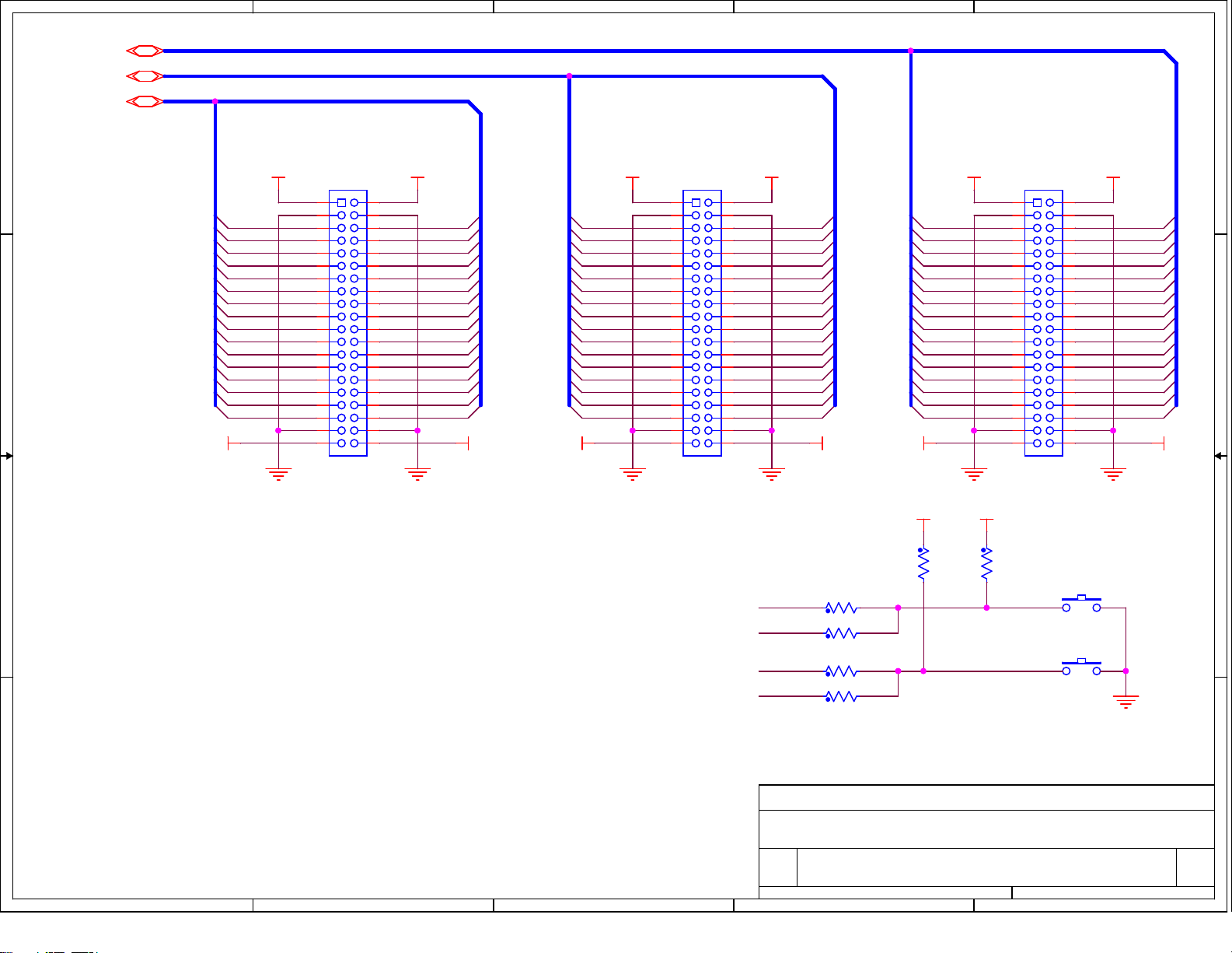
MICROPROCESSOR GPIO PORT CONNECTORS
PA[31:0]
PB[31:0]
PC[31:0]
D D
TP3
TP3
TP8
GND
GND
TP8
ACTIVE
ACTIVE
ACTIVE
3V3 3V3 3V3 3V33V33V3
TP2
TP2
GND
GND
C C
B B
3V3
GND
PC0
PC1
PC2
PC3
PC4
PC5
PC6
PC7
PC8
PC9 ACTIVE
PC10 ACKIRQ
PC11 RT1ENA
PC12 RT1TF
PC13 RT1BSY
PC14 RT2TF
PC15 RT2BSY
GND
PIN 1
1 2
3 4
5 6
7 8
9 10
11 12
13 14
15 16
17 18
19 20
21 22
23 24
25 26
27 28
29 30
31 32
33 34
35 36
37 38
39 40
Header 2x20
Header 2x20
J4
J3
J3
HEADER ORIENTATION
ON THE CIRCUIT BOARD
3V3 3V33V3 3V33V3
GND GNDGND
THIS PART OF
J4 IS NOT USED
PC16
PC17
PC18
PC19 PA3
PC20
PC21
PC22
PC23
PC24EECOPY
PC25nMR
PC26RT2ENA
PC27MTRUN
PC28BCENA
PC29BCTRG
PC30nLED1
PC31nLED2
PB0 PKTRDY
PB1 nIRQ
PB2 READY
PB3 CPYRQ
PB4 AUTOEN
PB5
PB6
PB7
PB8
PB9
PB10
PB11
PB12
PB13
PB14
PB15
J5B
J4
J4
1 2
3 4
5 6
7 8
9 10
11 12
13 14
15 16
17 18
19 20
21 22
23 24
25 26
27 28
29 30
31 32
33 34
35 36
37 38
39 40
Header 2x20
Header 2x20
GNDGND
TP10
TP10
3V3
3V3
PB16BENDI
PB17
PB18
PB19
PB20
PB21
PB22
PB23
PB24
PB25
PB26
PB27
PB28
PB29
PB30
PB31
3V3
LED1LED1
LED2LED2
LED3LED3
LED4LED4
LED5LED5
PA0 nRT1MC8
PA1 nRT2MC8
PA2
PA4
PA5
PA6
PA7
PA8
PA9
PA10
PA11
PA12
PA13 MISO
PA14 MOSI
PA15 SCK
STATUS LEDS
J5
J5
1 2
3 4
5 6
7 8
9 10
11 12
13 14
15 16
17 18
19 20
21 22
23 24
25 26
27 28
29 30
31 32
33 34
35 36
37 38
39 40
Header 2x20
Header 2x20
RL1 nLED1
R8
RL2
R9
R10
R10
RL4
R11
R11
RL5 nLED5
R12
R12
150R8150
150R9150
150
150
150
150
150
150
nLED2
nLED3RL3
nLED4
PA16nPCS0
PA17nTSTSS
PA18
PA19
PA20
PA21
PA22
PA23
PA24
PA25
PA26
PA27
PA28
PA29nLED3
PA30nLED4
PA31nLED5
GREEN - BUS A
GREEN - BUS B
GREEN
RED
AMBER
THIS PART OF
J5 IS NOT USED
MCU I/O HEADERS & LEDS
A A
PIN 1
J3
5
THIS PART OF
J3 IS NOT USED
4
J5A
PIN 1
3
HOLT INTEGRATED CIRCUITS, Mission Viejo, CA, USA
Title
Title
Title
HI-6131 EVAL PCB (Use With Std ARM CM3 Lower PCB)
HI-6131 EVAL PCB (Use With Std ARM CM3 Lower PCB)
HI-6131 EVAL PCB (Use With Std ARM CM3 Lower PCB)
Size Document Number Rev
Size Document Number Rev
Size Document Number Rev
A
A
A
6131 EVAL TOP.DSN A
6131 EVAL TOP.DSN A
6131 EVAL TOP.DSN A
Date: Sheet
Date: Sheet
Date: Sheet
2
24Thursday, October 06, 2011
24Thursday, October 06, 2011
24Thursday, October 06, 2011
of
of
of
1
Page 27
5
4
3
2
1
D D
3V3 3V3
RT1 CONFIG
SMD 5-POS DIP Switch
SMD 5-POS DIP Switch
CT2195LPST-ND
PC[31:0]
PC16 RT1ENA
RT1LOCK
RT1SSF
PC12 RT1TF
PC13 RT1BSY
C C
ON (CLOSED)
ON (CLOSED)
3
2145
3
2145
R13
R13
47K
47K
SW4
SW4
R14
R14
47K
47K
PC[31:0]
T[7:0]
PC[31:0]
SMD 5-POS DIP Switch
SMD 5-POS DIP Switch
CT2195LPST-ND
PC26 RT2ENA
T6 RT2LOCK
T7 RT2SSF
PC14 RT2TF
RT2BSYPC15 RT2BSY
FOR ALL DIP SWITCHES
UP = LOGIC-1
ON (CLOSED)
ON (CLOSED)
3
2145
3
2145
R15
R15
47K
47K
SW1
SW1
R16
R16
47K
47K
PB[31:0]
PC[31:0]
CONFIGURATION
CT21910LPST-NDRT2 CONFIG
SMD 10-POS DIP Switch
SMD 10-POS DIP Switch
PB4 AUTOEN
PB3 CPYRQ
BENDIPB16
TXINHA
TXINHB
MTSTOFF
RAMEDC
TEST
PC28 BCENA
PC27 MTRUN
ON (CLOSED)
ON (CLOSED)
3
21 456
3
21 456
87 109
87 109
3V3
SW8
SW8
R17
R17
2.2K
2.2K
R17 SMALL
VALUE TO
SWAMP OUT
INTERNAL
50K PULL-UP
R18
R18
47K
47K
T[7:0]
RT1AP
RT1A0
RT1A1
RT1A2
RT1A3
RT1A4
3
21 456
3
SW5
B B
SW5
21 456
REMOTE
TERMINAL 1
ADDRESS
ON (CLOSED)
ON (CLOSED)
SMD 6-POS DIP Switch
SMD 6-POS DIP Switch
T5 RT2AP
RT2A0T0
RT2A1T1
RT2A2T2
RT2A3T3
RT2A4T4
SW6
SW6
3
21 456
3
21 456
REMOTE
TERMINAL 2
ADDRESS
ON (CLOSED)
ON (CLOSED)
SMD 6-POS DIP Switch
SMD 6-POS DIP Switch
CT2196LPST-ND CT2196LPST-ND
DIP SWITCHES & SERIAL EEPROM
A A
5
4
ALL DIP SWITCH
SIGNALS WITH
A PULL-UP OR
A PULL-DOWN
GO TO THE MCU.
3
HOLT INTEGRATED CIRCUITS, Mission Viejo, CA, USA
Title
Title
Title
HI-6131 EVAL PCB (Use With Std ARM CM3 Lower PCB)
HI-6131 EVAL PCB (Use With Std ARM CM3 Lower PCB)
HI-6131 EVAL PCB (Use With Std ARM CM3 Lower PCB)
Size Document Number Rev
Size Document Number Rev
Size Document Number Rev
A
A
A
6131 EVAL TOP.DSN A
6131 EVAL TOP.DSN A
6131 EVAL TOP.DSN A
Date: Sheet
Date: Sheet
Date: Sheet
2
34Thursday, October 06, 2011
34Thursday, October 06, 2011
34Thursday, October 06, 2011
of
of
of
1
Page 28
5
4
3
2
1
DUAL EEPROM CIRCUIT FOR EVALUATION BOARD ONLY. SW2 SELECTS EEPROM.
JP1 JUMPER ALSO PROVIDES MCU READ/WRITE ACCESS TO SELECTED EEPROM.
D D
JUMPERS NORMALLY
SPAN COLUMNS A-B
FOR HI-613X CONTROL
OF SERIAL EEPROM.
FOR DIAGNOSTIC TESTS,
JUMPERS SPAN COLUMNS
B-C SO THE MCU SPI CAN
READ/WRITE THE SERIAL
EEPROM. THE C PROGRAM
CONTROLS TEST SLAVE
SELECT SIGNAL, nTSTSS.
C C
DECOUPLING
U2 & U3
C10
C10
100nF
100nF
3V3
C11
C11
100nF
100nF
PC[31:0]
PA[31:0]
nECS
EMISO
EMOSI
ESCK
HOST
SPI PORT
HI-6120
SPI TO
EEPROM
PC25 nMR
PA17 nTSTSS
PA13 MISO
PA14 MOSI
PA15 SCK
PA16nPCS0
A1
A2
A3
A4
Header 5x3
Header 5x3
JP1
JP1
A B C
C1
B1
C2
B2
C3
B3
C4
B4
C5A5
B5
R19 47KR19 47K
AUTO-INIT
SELECT
------- DEMO
EEPROM
2
USER
EEPROM
IN DIAGNOSTIC MODE, HI-6131
nCE
CHIP ENABLE IS DISABLED.
3V3
SW2
SW2
Switch SPDT
Switch SPDT
nECS1
1
nECS2
3
MEM_MISO
MEM_MOSI
MEM_SCK
R30 10KR30 10K
1
CS
SO
WP
GND
CS
SO
WP
GND
U2
U2
U3
U3
VCC
HOLD
SCK
VCC
HOLD
SCK
SI
SI
2
3
4
EEPROM 25LC512 8-SOIC
EEPROM 25LC512 8-SOIC
R31 10KR31 10K
1
2
3
4
EEPROM AT25512 8-SOIC
EEPROM AT25512 8-SOIC
3V3
8
7
6
5
3V3
8
7
6
5
TYPICAL APPLICATION REPLACES ABOVE EEPROM
B B
CIRCUIT WITH THIS SIMPLE CONFIGURATION
HI-6120
SPI TO
EEPROM
nECS
EMISO
PC[31:0]
A A
EMOSI
ESCK
5
PC25 nMR
R30 10KR30 10K
1
CS
2
SO
3
WP
4
GND
EEPROM 25LC512 8-SOIC
EEPROM 25LC512 8-SOIC
4
U2
U2
VCC
HOLD
SCK
3V3
C10
C10
100nF
8
7
6
5
SI
100nF
HI-6131 PQFP & 1553 BUS
HOLT INTEGRATED CIRCUITS, Mission Viejo, CA, USA
Title
Title
Title
HI-6131 EVAL PCB (Use With Std ARM CM3 Lower PCB)
HI-6131 EVAL PCB (Use With Std ARM CM3 Lower PCB)
HI-6131 EVAL PCB (Use With Std ARM CM3 Lower PCB)
Size Document Number Rev
Size Document Number Rev
Size Document Number Rev
A
A
A
6131 EVAL TOP.DSN A
6131 EVAL TOP.DSN A
6131 EVAL TOP.DSN A
Date: Sheet
Date: Sheet
3
Date: Sheet
2
44Thursday, October 06, 2011
44Thursday, October 06, 2011
44Thursday, October 06, 2011
of
of
of
1
Page 29
Bill of Materials
p
ARM Cortex M3 MCU Board
Item Qty
1
2 1 PCB, Bare, Evaluation Board N/A -------3 1 Ferrite Bead, 220 Ohm @ 100MHz 300mA DC 0805 FB1 732-1602-1-ND Wurth 742792034
4 2 Capacitor, Ceramic 10nF 10% 50V X7R 0603 C1,C42 490-1512-1-ND Murata GRM188R71H103KA01D
5 2 Capacitor, Ceramic 10pF 10% NP0 C0G 0V 0603 C23,C34 490-1403-1-ND Murata GRM1885C1H100JA01D
6 4 Capacitor, Ceramic 20pF 5% NP0 C0G 0V 0603 C14,C21,C25, C27 490-1410-1-ND Murata GRM1885C1H200JA01D
7 29 Capacitor, Ceramic 100nF 10% 25V Y5V 0603 C2,C4,C6-C11, C13,C15-C19,C22,C24,C26,C28,C29,C33,
8 4 Capacitor, Tantalum 4.7uF 10% 10V Low ESR SMD 1206 C5,C20,C31, C32 478-2391-1-ND AVX TPSA475K010R1400
9 4 Capacitor, Tantalum 10uF 10% 10V Low ESR SMD 1206 C3,C12,C30,C41 478-3317-1-ND AVX TPSA106K010R1800
10 1 Capacitor 22uF 10% 6.3V Tantalum Low ESR SMD C C43 399-10521-1-ND Kemet T495C226K006ATE380
11 1 Capacitor 100uF 10% 6.3V Tantalum Low ESR SMD C C44 495-1509-1-ND Kemet T495C107K006ZTE150
12 1 Header, Male Shrouded 2x10, 0.1" Pitch J1 HRP20H-ND Assmann AWHW20G-0202-T
13 1 Connector, Receptacle USB Mini B Rt-Angle PCB Mount J2 H2959CT-ND Hirose UX60-MB-5ST
14 1 Connector DB9F, Right-Angle PCB Short Body, Board Lock J6 AE10924-ND Assman A-DF-09-A/KG-T4S
15 1 Jack, DC Power, 2.5mm ID x 2.1mm pin J7 CP-102AH-ND Cui PJ-102AH
16 3 Receptacle, Female 2x20, 0.1" Pitch, 8.5mm Height, 3.2mm Solder Tails J3,J4,J5 S6104-ND Sullins PPTC202LFBN-RC
17 1 Solder Jumper JP1 SOLDER OPEN
18 2 Inductor, 10uH,100mA 0805 L1,L2 490-4029-1-ND Murata LQM21FN100M70L
19 1 LED Green 0805 LED1 160-1179-1-ND LiteOn LTST-C170GKT
20 0 Resistor, Prov 1/8W 0805 R1,R15,R16, R44,R45 DO NOT STUFF
21 7 Resistor, 0 ohm 1/8W 0805 R9,R12,R13, R14,R22,R23, R29 P0.0ACT-ND Panasonic ERJ-6GEY0R00V
22 2 Resistor, 1.0 5% 1/8W 0805 R7,R8 P1.0ACT-ND Panasonic ERJ-6GEYJ1R0V
23 2 Resistor, 39 5% 1/8W 0805 R4,R5 P39ACT-ND Panasonic ERJ-6GEYJ390V
24 1 Resistor, 150 5% 1/8W 0805 R17 P150ACT-ND Panasonic ERJ-6GEYJ151V
25 1 Resistor, 4.7K 5% 1/8W 0805 R3 P4.7KACT-ND Panasonic ERJ-6GEYJ472V
26 1 Resistor, 6.8K 5% 1/8W 0805 R6 P6.8KACT-ND Panasonic ERJ-6GEYJ682V
27 0 Resistor, 47K 5% 1/8W 0805 R18 DO NOT STUFF Panasonic ERJ-6GEYJ473V
28 0 Resistor, 68K 5% 1/8W 0805 R19 DO NOT STUFF Panasonic ERJ-6GEYJ683V
29 11 Resistor,100K 5% 1/8W 0805 R2,R10,R11, R20,R21,R24, R25,R26,R27, R28,R42 P100KACT-ND Panasonic ERJ-6GEYJ104V
30 3 Switch Tactile SPST 6 x 6 mm SMT SW1,SW2,SW3 P12932SCT-ND Panasonic EVQ-Q2B03W
31 2 Test Point, Black Insulator, 0.062" hole TP2,TP3 5011K-ND Keystone 5011
32 1 Test Point, Red Insulator, 0.062" hole TP1 5010K-ND Keystone 5010
33 1 IC, MCU 32-Bit 256KB Flash, 144-LQFP U1 ATSAM3U4EA-AU-ND Atmel ATSAM3U4EA-AU
34 1 4-Ch TVS ESD Protection SOT23-6 U2 296-28203-1-ND TI TPD4E001DBVR
35 1 IC, RS232 Driver/Receiver 3.0 to 5.5VDC 16-SOIC (3.9mm wide) U3 296-19752-1-ND Texas Inst MAX3232EIDR
36 1 IC Voltage Regulator 3.3V 1A LDO, SOT-223 U5 497-1228-1-ND ST Micro LD1117AS33TR
37 1 PolyZen 5.6V PPTC protected Zener SMD U6 ZEN056V130A24LSCT-ND TE ZEN056V130A24LS
38 1 Filter, EMI 35dB 10A 1MHz-1GHz SMD U7 490-5052-1-ND Murata BNX022-01L
39 1 IC Voltage Ref 2.5V 1% Micropower SOT-23 VR1 576-1047-1-ND Micrel LM4040DYM3-2.5
40 1 Crystal 12.00MHz, 50ppm 20pF, HC-49US leaded Y1 631-1105-ND Fox FOXSLF/120-20
41 1 Crystal, 32768 Hz 12.5pF cylinder leaded Y2 535-9033-1-ND Abracon AB26TRB-32.768KHZ-T
42 5 Rubber Foot, Bumpon Black Hemisphere, .312 X.200 H Place at 4 corners and center SJ5746-0-ND 3M SJ61A1
47 1 Capacitor, Ceramic 100nF, -20% / +80% 25V Y5V 0603 C66 490-1575-1-ND Murata GRM188F51E104ZA01D
48 1 Capacitor, Ceramic 33pF, 5% 50V C0G 0603 C59 490-1415-1-ND Murata GRM1885C1H330JA01D
49 2 Capacitor, Ceramic 15pF, 5% 50V C0G 0603 C60,C61 490-1407-1-ND Murata GRM1885C1H150JA01D
54 1 Ferrite Bead, 220 Ohm @ 100MHz 300mA DC 0805 FB2 732-1602-1-ND Wurth 742792034
55 1 Solder Jum
56 1 Connector, Receptacle USB Mini B Rt-Angle PCB Mount J8 H2959CT-ND Hirose UX60-MB-5ST
57 1 LED Green 0805 LED2 160-1179-1-ND LiteOn LTST-C170GKT
59 1 Resistor, 220 ohm 5% 1/10W 0603 R31 P220GCT-ND Panasonic ERJ-3GEYJ221V
63 2 Resistor, 27 ohm 5% 1/10W 0603 R36,R38 P27GCT-ND Panasonic ERJ-3GEYJ270V
66 1 4-Ch TVS ESD Protection SOT23-6 U4 296-28203-1-ND TI TPD4E001DBVR
Description Reference DigiKey Mfr P/N
C35-C40,C45-46,C54
er JP2 SOLDER OPEN
Rev. E
490-1575-1-ND Murata GRM188F51E104ZA01D
Page 30
5
4
3
2
1
D D
USB2.0
POWER SUPPLY
PORT
J4
J5
J4
J5
USB
DEBUG
PORT
ARM
CORTEX M3
HI-6XXX
MCU
JTAG/
DEBUG
PORT
C C
J3
J3
SERIAL
PORT
BUTTONS
LOWER CIRCUIT BOARD STACKING UPPER CIRCUIT BOARD
B B
J3,J4 & J5 ARE DUAL-ROW STACKING
RECEPTACLES (LOWER BOARD) AND
HEADERS (UPPER BOARD).
A A
5
4
3
HOLT INTEGRATED CIRCUITS, Mission Viejo, CA, USA
Title
Title
Title
ARM CORTEX M3 MICROCONTROLLER BOARD
ARM CORTEX M3 MICROCONTROLLER BOARD
ARM CORTEX M3 MICROCONTROLLER BOARD
Size Document Number Rev
Size Document Number Rev
Size Document Number Rev
Date: Sheet of
Date: Sheet of
Date: Sheet of
CM3 BOARD REV E.DSN E
A
CM3 BOARD REV E.DSN E
A
CM3 BOARD REV E.DSN E
A
1 7Wednesday, June 01, 2016
1 7Wednesday, June 01, 2016
2
1 7Wednesday, June 01, 2016
1
Page 31
5
4
3
2
1
PA[31:0]
PA0
PA1
PA2
D D
PA3
PA4
PA5
PA6
PA7
PA8
PA9
PA10
PA11
PA12
PA13
PA14
PA15
PA16
PA17
PA18
PA19
PA20
C C
PA21
PA22
PA23
PA24
PA25
PA26
PA27
PA28
PA29
PA30
PA31
PC[31:0]
U1A
SAM3U
109
111
113
115
117
119
121
123
128
130
132
133
134
87
88
91
93
95
99
100
101
102
77
103
105
106
107
64
45
46
78
48
PA0/WKUP0
PA1/WKUP1
PA2/WKUP2
PA3/CK
PA4/CDA
PA5/DA0
PA6/DA1
PA7/DA2
PA8/DA3
PA9/TWD0
PA10/TWCK0
PA11/URXD
PA12/UTXD
PA13/MISO
PA14/MOSI
PA15/SPCK
PA16/NPCS0
PA17/WKUP7
PA18/WKUP8
PA19/WKUP9
PA20/TXD1
PA21/RXD1
PA22/RTS1
PA23/CTS2
PA24/WKUP11
PA25/WKUP12
PA26/TD
PA27/PCK0
PA28/TK
PA29/PWMH1
PA30/TF
PA31/RF
PB0/PWMH0
PB1/PWMH1
PB2/PWMH2
PB3/AD12BAD2
PB4/AD12BAD3
PB5/AD1
PB6/D15
PB7/A0/NBS0
PB8/A1
PB9/D0
PB10/D1
PB11/D2
PB12/D3
PB13/D4
PB14/D5
PB15/D6
PB16/D7
PB17/NANDOE
PB18/NANDWE
PB19/NRD
PB20/NCS0
PB21/A21/NANDALE
PB22/A22/NANDCLE
PB23/NWR0/NWE
PB24/NANDRDY
PB25/D8
PB26/D9
PB27/D10
PB28/D11
PB29/D12
PB30/D13
PB31/D14
53
55
57
79
80
65
66
67
68
31
30
59
61
62
29
97
96
26
25
24
23
21
20
19
15
14
13
12
10
8
6
5
PB[31:0]
PB0
PB1
PB2
PB3
PB4
PB5
PB6
PB7
PB8
PB9
PB10
PB11
PB12
PB13
PB14
PB15
PB16
PB17
PB18
PB19
PB20
PB21
PB22
PB23
PB24
PB25
PB26
PB27
PB28
PB29
PB30
PB31
PC[31:0]
PC0
PC1
PC2
B B
PC3
PC4
PC5
PC6
PC7
PC8
PC9
PC10
PC11
PC12
PC13
PC14
PC15
110
PC0/A2
112
PC1/A3
114
PC2/A4
116
PC3/A5
118
PC4/A6
120
PC5/A7
122
PC6/A8
124
PC7/A9
129
PC8/A10
131
PC9/A11
89
PC10/A12
92
PC11/A13
94
PC12/NCS1
98
PC13/RXD3
28
PC14/NPCS2
81
PC15/NWR1/NBS1
PC16/NCS2
PC17/AD12BAD6
PC18/AD12BAD7
PC19/NPCS1
PC20/A14
PC21/A15
PC22/A16
PC23/A17
PC24/A18
PC25/A19
PC26/PWMH2
PC27/A23
PC28/DA4
PC29/DA5
PC30/DA6
PC31/DA7
82
83
84
32
108
22
47
49
54
56
58
63
69
70
71
72
PC16
PC17
PC18
PC19
PC20
PC21
PC22
PC23
PC24
PC25
PC26
PC27
PC28
PC29
PC30
PC31
ARM CORTEX M3 PIO
A A
5
4
3
HOLT INTEGRATED CIRCUITS, Mission Viejo, CA, USA
Title
Title
Title
ARM CORTEX M3 MICROCONTROLLER BOARD
ARM CORTEX M3 MICROCONTROLLER BOARD
ARM CORTEX M3 MICROCONTROLLER BOARD
Size Document Number Rev
Size Document Number Rev
Size Document Number Rev
Date: Sheet of
Date: Sheet of
Date: Sheet of
CM3 BOARD REV E.DSN E
A
CM3 BOARD REV E.DSN E
A
CM3 BOARD REV E.DSN E
A
2 7Wednesday, June 01, 2016
2 7Wednesday, June 01, 2016
2
2 7Wednesday, June 01, 2016
1
Page 32
5
4
3
2
1
U1B
+3V3
JP1
+3V3
R1 PROV
R2 100K
D D
C1
10nF
nRST
NRSTB
TDI
TDO
TMS
TCK
DHSDP
DHSDM
R4 39R
R5 39R
C C
C14
20pF
DFSDM
DFSDP
XIN32
XOUT32
XIN
Y1
C21
20pF
12.000MHz
XOUT
VBG
B B
R6
6.8K 1%
C23
10pF
SAM3U
137
ERASE
138
TEST
142
JTAGSEL
135
FWUP
136
SHDN
11
NRST
141
NRSTB
1
TDI
4
TDO/TRACESWO
7
TMS/SWDIO
9
TCK/SWCLK
37
DHSDP
38
DHSDM
41
DFSDM
42
DFSDP
144
XIN32
143
XOUT32
36
XIN
35
XOUT
39
VBG
R3 4.7K
VOUT
+
+3V3
C12
10uF
ADVREF
AD12BVREF
VDDIN
VDDOUT
VDDCORE1
VDDCORE2
VDDCORE3
VDDCORE4
VDDCORE5
VDDCORE6
VDDPLL
74
76
3
2
16
27
44
50
86
125
34
VREF
VOUT
C4
100nF
VOUT
C5
4.7uF
C6
100nF
C2
100nF
C7
100nF
+3V3
C8
100nF
+
C3
10uF
VR1
LM4040-2.5
SOT-23
C9
100nF
3
2 1
AVX TPSA106K010R1800
C10
100nF
C11
100nF
C13
100nF
VDDIO1
VDDIO2
VDDIO3
VDDIO4
VDDIO5
VDDUTMI
17
51
85
104
127
40
VUTMI
C15
100nF
C16
100nF
C17
100nF
C18
100nF
C19
100nF
+3V3
C20
4.7uF
C22
100nF
VANA
C24
XIN32
C25
20pF
VDDANA
73
100nF
GND1
GND252GND3
18
60
90
GNDPLL
GNDUTMI
GND4
GND5
126
GNDANA
GNDBU
33
43
75
140
VDDBU
139
+3V3
C26
100nF
Y2
32.768KHz
XOUT32
3
C27
1 2
20pF
+3V3 VUTMI VANA+3V3
+
A A
C30
10uF
L1
10uH/100mA
R7
1R
C28
0805 MURATA LQM21FN100M70
100nF
C31
4.7uF
5
4
L2
10uH/100mA
R8
1R
C32
4.7uF
C29
100nF
3
ARM CORTEX M3 MCU
HOLT INTEGRATED CIRCUITS, Mission Viejo, CA, USA
Title
Title
Title
ARM CORTEX M3 MICROCONTROLLER BOARD
ARM CORTEX M3 MICROCONTROLLER BOARD
ARM CORTEX M3 MICROCONTROLLER BOARD
Size Document Number Rev
Size Document Number Rev
Size Document Number Rev
Date: Sheet of
Date: Sheet of
Date: Sheet of
CM3 BOARD REV E.DSN E
A
CM3 BOARD REV E.DSN E
A
CM3 BOARD REV E.DSN E
A
3 7Wednesday, June 01, 2016
3 7Wednesday, June 01, 2016
2
3 7Wednesday, June 01, 2016
1
PROVISIONAL
Page 33
5
4
3
2
1
PA[31:0]{1,4}
PB[31:0]{1,3,5}
PC[31:0]{1,3}
D D
+3V3
J3
1 2
3 4
PC0
PC1
PC2
PC3
PC4
PC5
PC6
PC7
PC8
PC9
C C
PC10
PC11
PC12
PC13
PC14
PC15
+3V3 +3V3 +3V3 +3V3 +3V3+3V3
5 6
7 8
9 10
11 12
13 14
15 16
17 18
19 20
21 22
23 24
25 26
27 28
29 30
31 32
33 34
35 36
37 38
39 40
Header 2x20
+3V3 +3V3 +3V3 +3V3+3V3
J4
1 2
3 4
PC16
PC17
PC18
PC19
PC20
PC21
PC22
PC23
PC24
PC25
PC26
PC27
PC28
PC29
PC30
PC31
PB0
PB1
PB2
PB3
PB4
PB5
PB6
PB7
PB8
PB9
PB10
PB11
PB12
PB13
PB14
PB15
5 6
7 8
9 10
11 12
13 14
15 16
17 18
19 20
21 22
23 24
25 26
27 28
29 30
31 32
33 34
35 36
37 38
PB16
PB17
PB18
PB19
PB20
PB21
PB22
PB23
PB24
PB25
PB26
PB27
PB28
PB29
PB30
PB31
PA0
PA1
PA2
PA3
PA4
PA5
PA6
PA7
PA8
PA9
PA10
PA11
PA12
PA13
PA14
PA15
39 40
Header 2x20
J5
1 2
3 4
5 6
7 8
9 10
11 12
13 14
15 16
17 18
19 20
21 22
23 24
25 26
27 28
29 30
31 32
33 34
35 36
37 38
39 40
Header 2x20
PA16
PA17
PA18
PA19
PA20
PA21
PA22
PA23
PA24
PA25
PA26
PA27
PA28
PA29
PA30
PA31
+3V3+3V3
R10
B B
PB17
PA7
R12
R44 PROV
0
100K
R11
100K
SW1
nSW1
SW2
PB18
PA8
R13
R45 PROV
0
nSW2
BOARD I/O HEADERS, BUTTONS
A A
5
4
3
HOLT INTEGRATED CIRCUITS, Mission Viejo, CA, USA
Title
Title
Title
ARM CORTEX M3 MICROCONTROLLER BOARD
ARM CORTEX M3 MICROCONTROLLER BOARD
ARM CORTEX M3 MICROCONTROLLER BOARD
Size Document Number Rev
Size Document Number Rev
Size Document Number Rev
Date: Sheet of
Date: Sheet of
Date: Sheet of
CM3 BOARD REV E.DSN E
A
CM3 BOARD REV E.DSN E
A
CM3 BOARD REV E.DSN E
A
4 7Wednesday, June 01, 2016
4 7Wednesday, June 01, 2016
2
4 7Wednesday, June 01, 2016
1
Page 34
5
4
3
2
FB1
BN03K314S300R
1
6
5
GND
4
NC
D D
DHSDP
DHSDM
3
2
1
R18 47K
VBUS_USB
DNI
R19
68K
DNI
C34
10pF
U2
TPD4E001DBVR
1
IO1
GND
IO2
IO4
VCC
IO3
2
3
DNI
C33
+3V3
100nF
6
USB Mini B Recept
5
4
C54
100nF
D+
DVBUS
J2
CASE
PA[31:0]
C C
+3V3
PA0
+3V3 +3V3
C35
100nF
R20
100K
TXD1
RXD1
RTS1
CTS1
UTXD
URXD
B B
PA20
PA21
PA22
PA23
PA12
PA11
R21
100K
R9 0R
R22 0R
R14 0R
R23 0R
R15 PROV
R16 PROV
C37
100nF
TP4
SMD
C38
100nF
RXDIN
TXDOUT
TP6
SMD
U3
MAX3232CSE
16
VCC
2
V+
6
V-
15
GND
11
T1IN
12
R1OUT
10
T2IN
9
R2OUT
C1+
C1-
C2+
C2-
T1OUT
R1IN
T2OUT
R2IN
1
3
4
5
14
13
7
8
C36
100nF
C39
100nF
TXD
RXD
RTS
CTS
J6
FEMALE RIGHT ANGLE
1
6
2
7
3
8
4
9
5
10
11
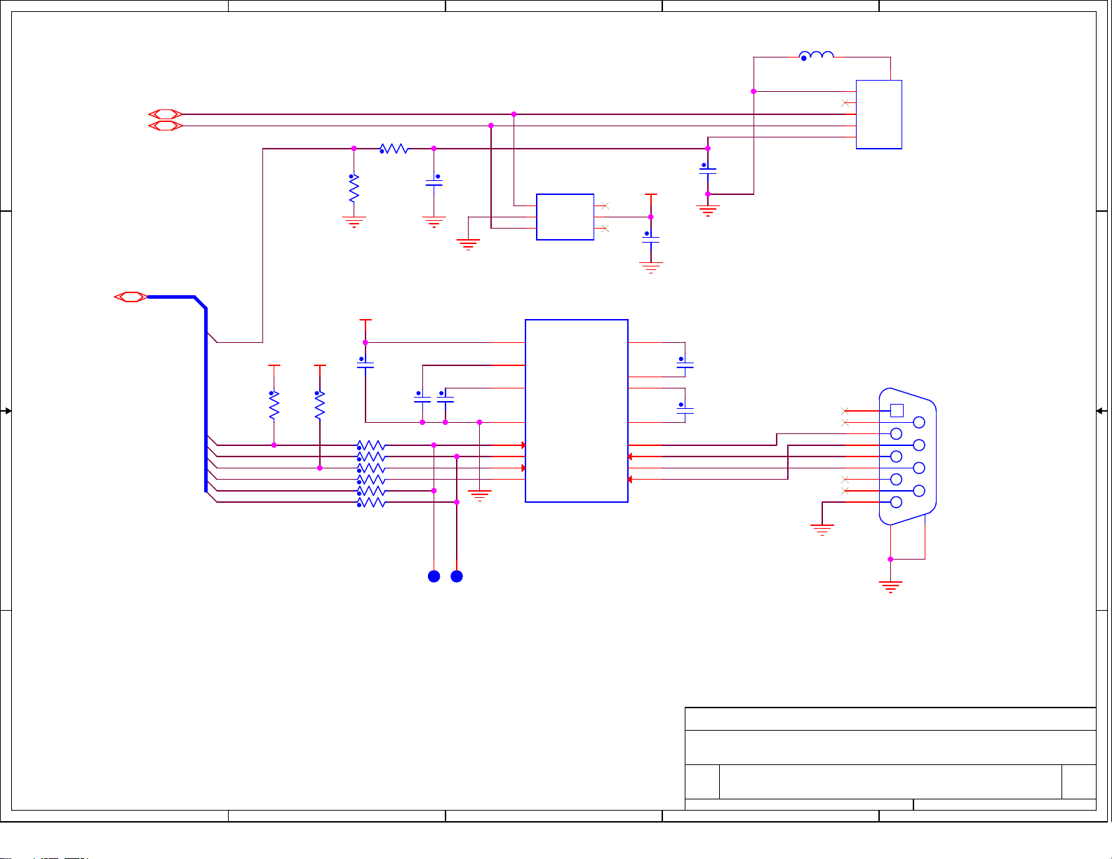
USB & RS-232 SERIAL
A A
5
4
3
HOLT INTEGRATED CIRCUITS, Mission Viejo, CA, USA
Title
Title
Title
ARM CORTEX M3 MICROCONTROLLER BOARD
ARM CORTEX M3 MICROCONTROLLER BOARD
ARM CORTEX M3 MICROCONTROLLER BOARD
Size Document Number Rev
Size Document Number Rev
Size Document Number Rev
Date: Sheet of
Date: Sheet of
Date: Sheet of
CM3 BOARD REV E.DSN E
A
CM3 BOARD REV E.DSN E
A
CM3 BOARD REV E.DSN E
A
5 7Wednesday, June 01, 2016
5 7Wednesday, June 01, 2016
2
5 7Wednesday, June 01, 2016
1
Page 35
5
D D
C C
J7 POWER JACK
U6
ZEN056V130A24LS
1
3
2
4
C45
100nF
U7
BNX022-01
1
SV
3
SG
CV
CG
3
SOT-223
U5
NCP1117ST33T3
3
IN
OUT
2
GND
2
+
C43
1
22uF
4
+
C44
100uF
2
+3V3+5V
POWER
1
TP1
+3V3
LED1
green-led
C46
R17
100nF
150R
TP2
GND
TP3
GND
B B
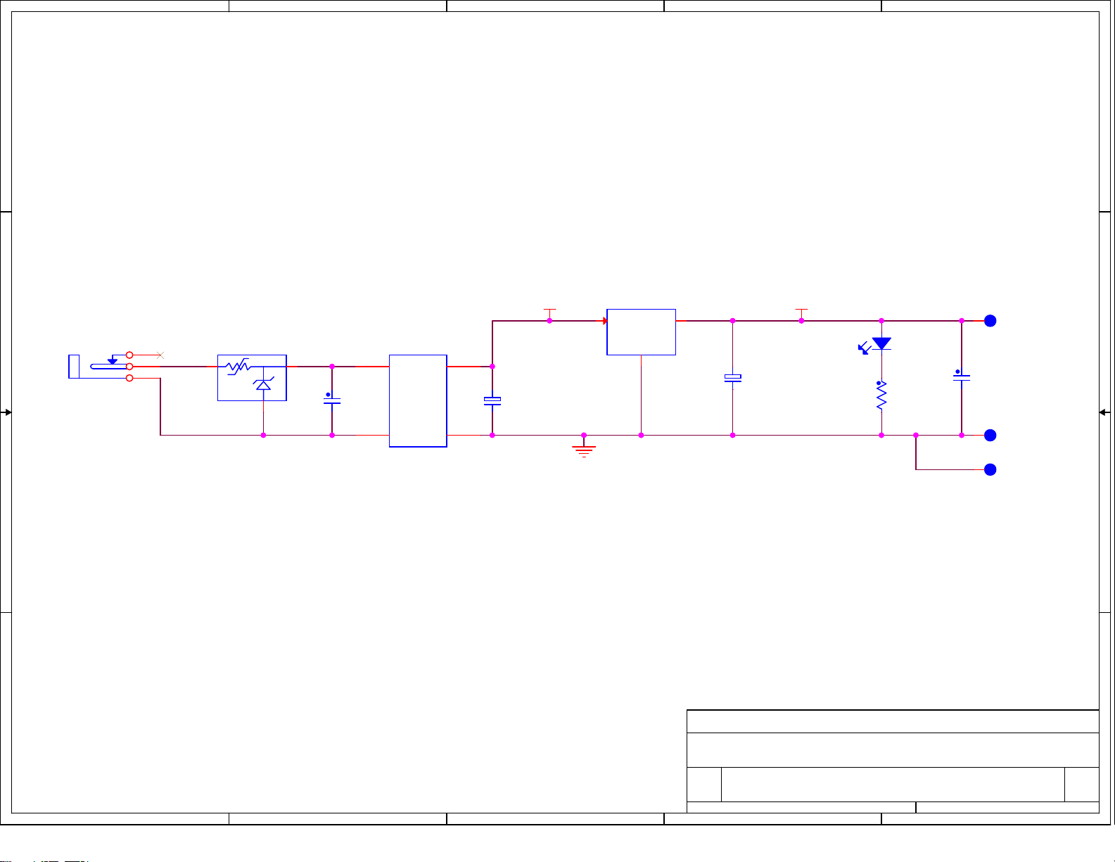
POWER SUPPLY
A A
5
4
3
HOLT INTEGRATED CIRCUITS, Mission Viejo, CA, USA
Title
Title
Title
ARM CORTEX M3 MICROCONTROLLER BOARD
ARM CORTEX M3 MICROCONTROLLER BOARD
ARM CORTEX M3 MICROCONTROLLER BOARD
Size Document Number Rev
Size Document Number Rev
Size Document Number Rev
Date: Sheet of
Date: Sheet of
Date: Sheet of
CM3 BOARD REV E.DSN E
A
CM3 BOARD REV E.DSN E
A
CM3 BOARD REV E.DSN E
A
6 7Wednesday, June 01, 2016
6 7Wednesday, June 01, 2016
2
6 7Wednesday, June 01, 2016
1
Page 36
5
4
3
2
1
LED2
C60
15pF
DISABLE J-LINK
R31 220
C61
15pF
JP2
R36 27
R38 27
C59
33pF
+3V3
green-led
D D
C C
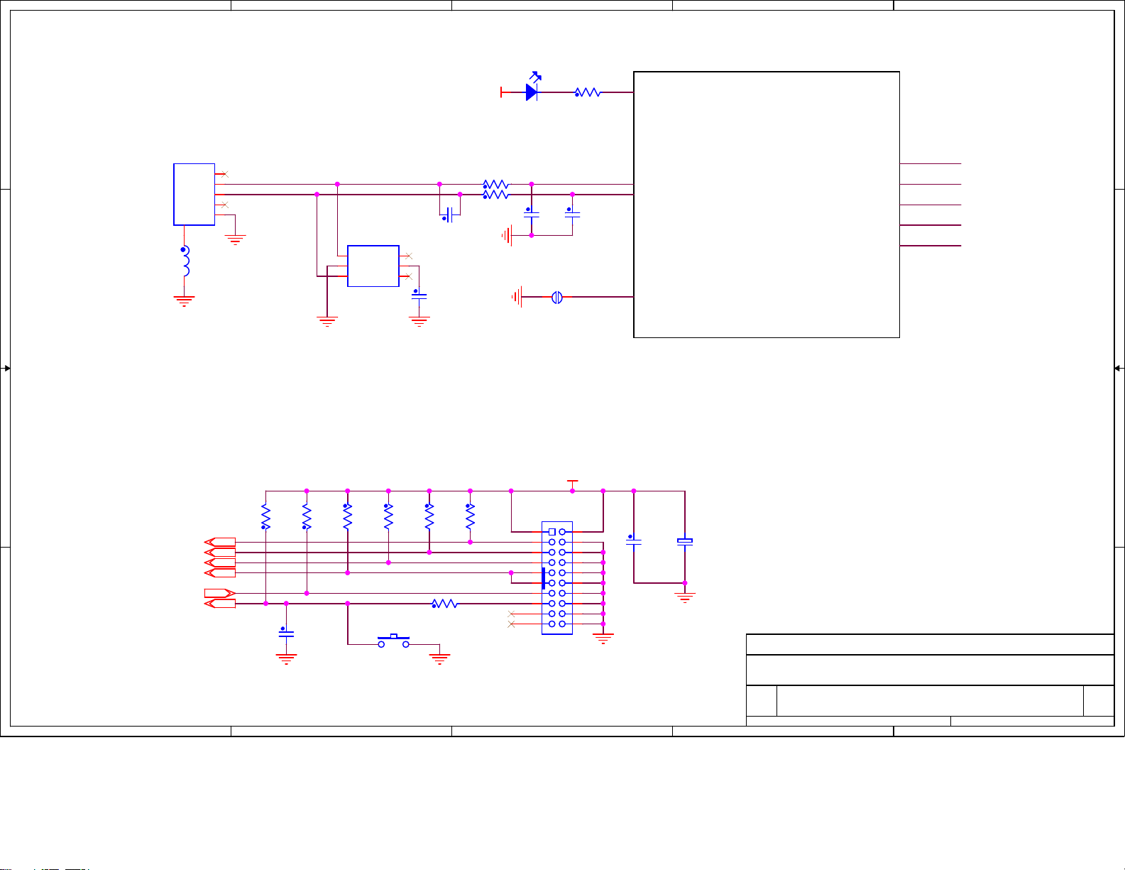
USB DEBUG INTERFACE
J8
USB Mini B Recept
1
VBUS
2
D-
3
D+
4
NC
5
GND
CASE
6
FB2
BN03K314S300R
U4
TPD4E001DBVR
1
IO1
GND
IO2
IO4
VCC
IO3
2
3
6
5
4
C66
100nF
SEGGER J-LINK ON-BOARD
DEBUGGER INTERFACE
(CONFIDENTIAL)
NOT PART OF A CUSTOMER DESIGN,
THIS BLOCK IS COMPRISED OF U8,
Y3, C47-C53, C55-C58, C62-C65, R30,
R32-R35, R37, R39-R41 AND R43.
TDI
TMS
TCK
TDO
nRST
DEBUGGER INTERFACE COPIED
FROM ATMEL ARM CORTEX M3
USE THIS TO CONNECT J-LINK IF ABOVE
CIRCUITRY IS NOT POPULATED OR WHEN
B B
IT IS DISABLED BY JUMPER JP2.
+3V3
100K
100K
R25
R26
R27
R24
R42
100K
100K
PARALLEL
DEBUG INTERFACE
A A
5
nTRST
TDI
TMS
TCK
TDO
nRST
C42
10nF
R29 0R
SW3
RESET
4
100K
R28
100K
nTRST
TDI
TMS
TCK
TDO
nSRST
J1
1 2
3 4
5 6
7 8
9 10
11 12
13 14
15 16
17 18
19 20
Header 2 x 10, Shrouded
3
C40
100nF
+
C41
10uF
HOLT INTEGRATED CIRCUITS, Mission Viejo, CA, USA
Title
Title
Title
ARM CORTEX M3 MICROCONTROLLER BOARD
ARM CORTEX M3 MICROCONTROLLER BOARD
ARM CORTEX M3 MICROCONTROLLER BOARD
Size Document Number Rev
Size Document Number Rev
Size Document Number Rev
CM3 BOARD REV E.DSN E
Custom
CM3 BOARD REV E.DSN E
Custom
CM3 BOARD REV E.DSN E
Custom
Date: Sheet of
Date: Sheet of
Date: Sheet of
2
7 7Wednesday, June 01, 2016
7 7Wednesday, June 01, 2016
7 7Wednesday, June 01, 2016
1
 Loading...