

HOLT ADK-8400 Quick Start Manual

QSG-8400 Rev. New Holt Integrated Circuits
ADK-8400 Evaluation Board
Quick Start Guide:
HI-8400 Isolated Discrete Sensor
with ±800V Isolation
July 2018
REVISION HISTORY
Revision
Date
Description of Change
QSG-8400, Rev. New
07-25-18
Initial Release
Holt Integrated Circuits
3
Introduction
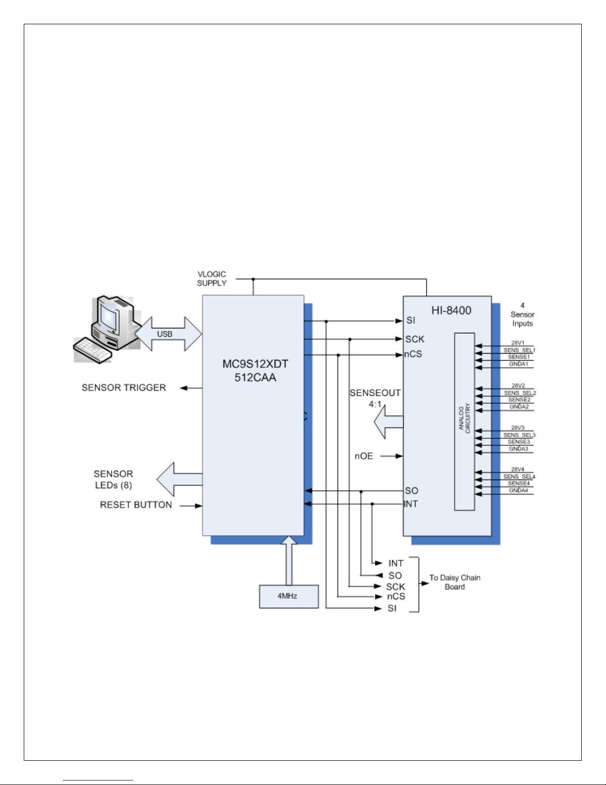
This board allows the customer to evaluate the features of the galvanically isolated HI-8400 four channel
discrete sensor IC. Each input has full isolation from the digital domain and from the other sensor inputs.
The HI-8400 logic is powered from a single 3.3V ±5% or 5V ±5% supply voltage. The isolated analog
sensor input is supplied from a 16 to 36VDC supply. Each input channel can be individually configured as
a GND/Open or Supply/Open Sensor type using hardware pins. Sensor thresholds are internally set at
Airbus ABD0100H levels, an SPI port is used to read sensor data. A second board is also included to allow
users to evaluate the daisy chain feature.
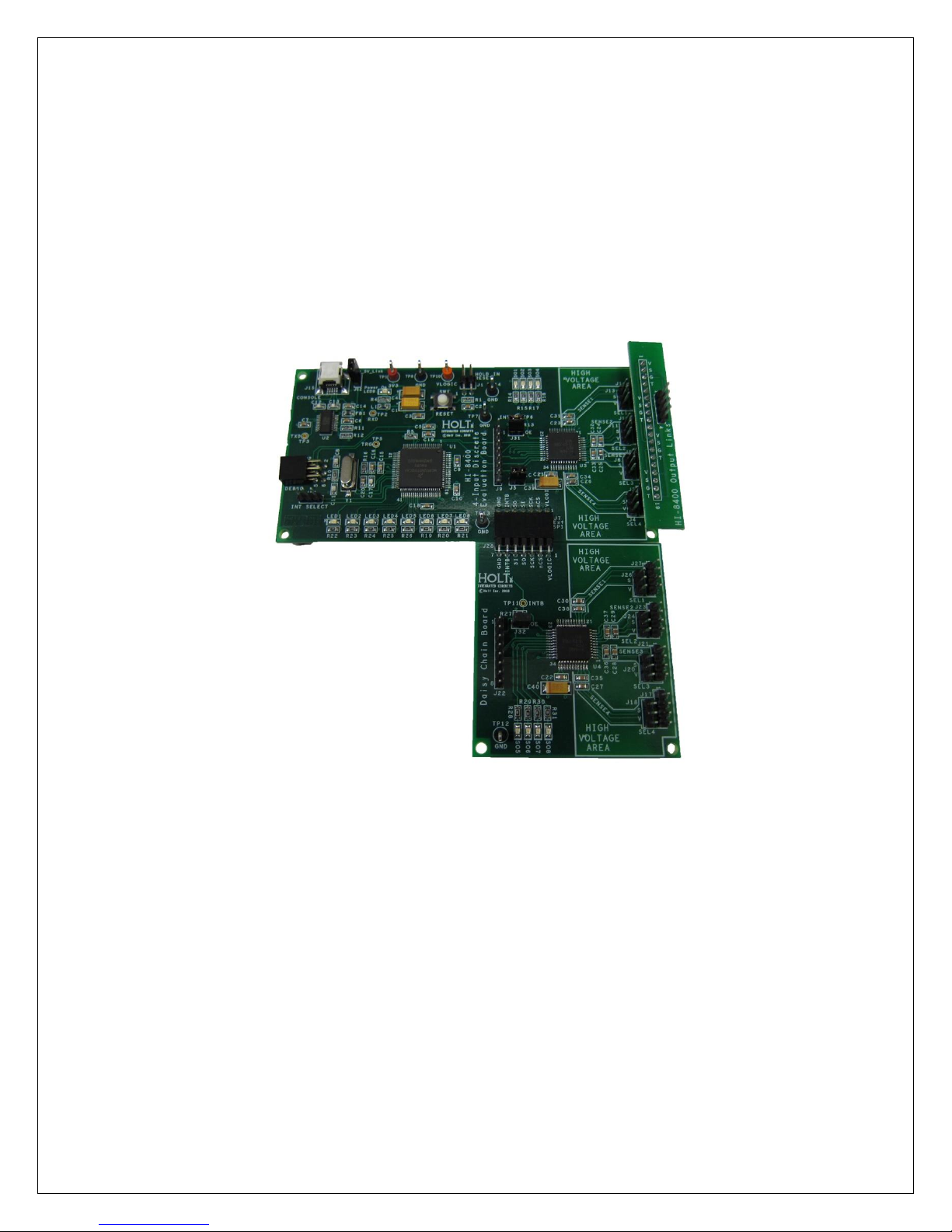
Figure 1 – Top View of HI-8400 Evaluation Set Up including Daisy Chain Board

Holt Integrated Circuits
4
WARNING – Before using High Voltage equipment ensure that you use
the best safety operating practices, including, but not limited to the
following precautions :
Do NOT work with high voltage by yourself, have another person (safety
observer), qualified in first aid for electrical shock, present at all times.
Use rubber gloves where applicable and stand on approved
rubber matting. Note that not all so-called rubber mats are good isolators.
Always discharge the high voltage from components or terminals by using
a safety probe. Do NOT hold the test probe when circuits over 300 volts
are tested.
Always use equipment certified for operation at or above the peak
voltages being tested.
Holt Integrated Circuits
5
KIT CONTENTS
● This User Guide.
● HI-8400 Evaluation Board.
● USB Flash drive with HI-8400 software
● USB to Mini USB Serial Cable.
Demonstration Set-up

Holt Integrated Circuits
6
Initial Board Set up
1. Make sure the board jumpers and switch positions match the default settings listed earlier.
The VLOGIC supply can also use a 3.3V or 5V supply, in the case of 5V there is the option of
using the USB supply by linking jumper J12 (this is the default set up), if you are not using
the USB supply J12 should be open. If using an external supply then connect a +3.3V or +5V
power supply to VLOGIC (RED) and 0V to GND terminals making sure J12 is open.
2. Each input channel of the HI-8400 is in its own isolated domain, the sensor type for each
input is set by control pins, these are referenced only to the GND of that input; there is no
common ground for the sensors inputs. Of course if desired all the sensor grounds of the
device can be connected together. To set an input to GND/Open the SENS_SELx input for
channelx must be connected to the GNDAx of that same channel. To set an input to
Supply/Open the SENS_SELx input for that channel must be connected to the 28Vx of that
same channelx. Jumpers J4, 6, 11, 13 on the board are provided to do this.
3. Reading of the sense data can be on the dedicated hardware pins SENSEOUT[1:4] or through
the on board MCU, and interfacing with a terminal emulator. When using the
SENSEOUT[1:4] pins, the nOE pin has to be low to enable the outputs. LEDS SO[1:4] are
used to monitor these sensor outputs. In GND/Open an illuminated LED means that sensor
is Open (High). In Supply/Open sensor mode an illuminated LED means that sensor is closed
or at Supply level (High).
4. Each channel requires its own 28V supply, the positive and negatives of each supply should
be connected to the 28Vx and GNDAx to pins on J3, J8, J10 and J14. Alternatively, the
breakout board supplied with the kit can be used if a common GND and 28V is to be used
for all four sense channels.
Software Control
1. Connect the mini USB lead to your PC and then to the console connector J15 on the HI-8400
board; your PC should automatically install the driver. If not the driver FT231 can be installed
from the Holt Flash drive. If you have problems installing the driver, please refer to the FTDI
website below:
2. http://www.ftdichip.com/Documents/InstallGuides.htm
 Loading...