

Page 1
Owner’s
Guide
HASF1521GRC
☎
INFO HOT-LINE: If, after reading this owner’s guide you
have any questions or comments, please call
1-800-5-HOLMES and a Consumer Service
Representative will be happy to assist you.
PLEASE READ AND SAVE THESE IMPORTANT INSTRUCTIONS
1166”
”
ST
ST
AND F
AND F
AN
AN
WITH
REMOTE CONTROL
Page 2
PLEASE READ AND SAVE
HASF 1522RC 9/00
THESE IMPORTANT
SAFETY INSTRUCTIONS
When using electrical appliances, basic safety precautions should always
be followed to reduce the risk of fire, electric shock, and injury to persons, including the following:
1) Read all instructions before using the appliance.
2) To avoid fire or shock hazard, plug the appliance directly into a 120 V
AC electrical outlet.
3) Keep the cord out of heavy traffic areas. DO NOT let the cord hang
over the edge of a table or counter. To avoid fire hazard, NEVER put
the cord under rugs, near heat registers, radiator, stoves, or heaters.
4) To protect against electrical hazards, DO NOT immerse in water or
other liquids. Do not use near water.
5) Close supervision is necessary when any appliance is used by or near
children, or by disabled people.
6) Always unplug the fan before moving it, putting on or taking off
parts, cleaning, or whenever the fan is not is use. Be sure to pull by
the plug and not the cord.
7) Avoid contact with moving parts. DO NOT operate without fan grills
properly in place.
8) DO NOT operate any appliance with a damaged cord or plug, if motor
fan fails to rotate, after the appliance malfunctions, or if it has been
dropped or damaged in any manner. Return appliance to manufacturer for examination, electrical or mechanical adjustment, or repair.
9) DO NOT operate in the presence of explosive and/or flammable
fumes.
10) Use appliance only for intended household use as described in this
manual. Any other use not recommended by the manufacturer may
cause fire, electric shock, or injury to persons. The use of attachments not recommended or sold by The Holmes Group (or Bionaire)
may cause hazards.
11) DO NOT use outdoors.
12) Always use on a dry, level surface.
13) Keep unit away from heated surfaces and open flames.
14) WARNING: To reduce the risk of fire or electric shock, DO NOT use
this fan with any solid-state speed control device.
15) DO NOT attempt to repair or adjust any electrical or mechanical functions on this unit. Doing so will void your warranty. The inside of the
unit contains no user serviceable parts. All servicing should be performed by qualified personnel only.
PLEASE READ AND SAVE
THESE IMPORTANT
SAFETY INSTRUCTIONS
THIS PRODUCT IS EQUIPPED WITH A POLARIZED AC
(Alternating Current)PLUG (a plug having one blade wider
than the other). This plug will fit into the power outlet
only one way. If the plug does not fit fully into the outlet,
reverse the plug. If it still does not fit, contact qualified
personnel to install the proper outlet.
DO NOT DEFEAT THE SAFETY PURPOSE OF THIS
POLARIZED PLUG IN ANY WAY.
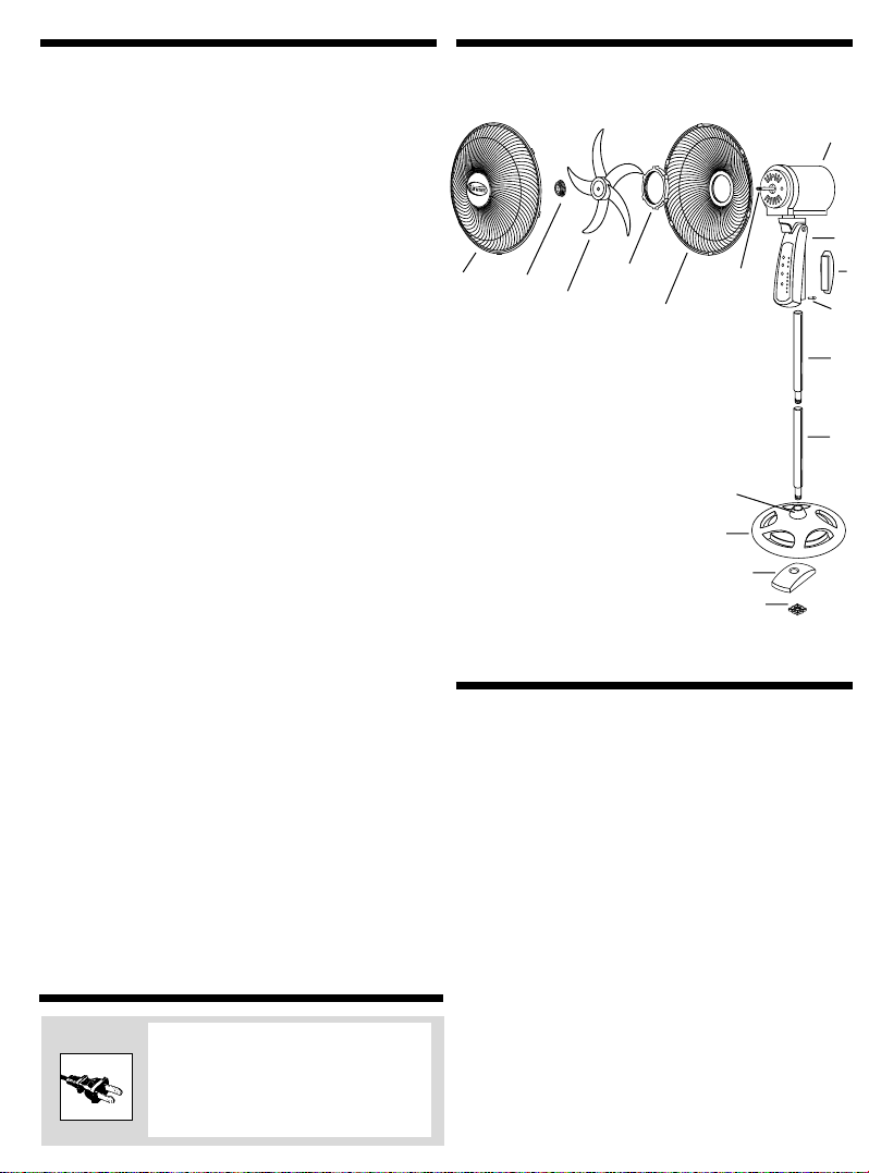
ILLUSTRATIONS
FIGURE 3
G
A
B
C
A. FRONT GRILL
B. FAN BLADE CAP
C. FAN BLADE
D. REAR GRILL NUT
E. REAR GRILL
F. MOTOR SHAFT
G. MOTOR HOUSING
H. REMOTE CONTROL HOUSING
I. REMOTE CONTROL
J. LOCKING NUT
K. UPPER EXTENSION POLE
L. LOWER EXTENSION POLE
M. BASE
N. WEIGHTED INSERT
O. BASE NUT
P. DECORATION COVER
D
E
F
P
M
N
O
ASSEMBLY INSTRUCTIONS
Base / Pole Assembly
Step 1: Insert the lower extension pole through the base cover and twist
the pole clockwise to lock in position. Be careful to align the cut-away
grooves on the threaded joint (male end) with the two protruding
raised pieces inside the hollow end of the base cover, See (figure #1).
Step 2: Turn the base cover upside down (with the lower extension pole
facing the floor) and place the weighted insert into the base cover.
The pole threads will be exposed as they protrude through the insert.
Step 3: Place the base nut on the threaded section and hand-tighten the
base nut to securely fasten the lower extension pole to the base.
NOTE: DO NOT USE A TOOL TO TIGHTEN THE BASE NUT
Step 4: Insert the upper extension pole with the threaded joint (male
end) into the hollow end of the lower extension pole (female end) –
See figure #2, until both poles meet. Be careful to align the cutaway
/ grooves on the threaded joint (male end) with the two protruding
pieces inside the hollow end of the lower extension pole (female
end).
Step 5: Turn the upper extension pole with the threaded joint clockwise
to lock it securely in place. (See figure #2).
G
H
I
J
K
L
Page 3

ASSEMBLY INSTRUCTIONS(CONT.)
Fan Head Assembly
You are now ready to assemble the fan head (See figure #3)
Step 1: Position the rear grill over the motor shaft, making certain the 2
notches at the top and bottom of the rear grill fit over the 2 protruding notches on the motor housing. Please make sure the rear grill fits
securely against the motor housing.
Step 2: Fasten the rear grill in place using the rear grill nut. Turn the nut
clockwise and tighten firmly.
Step 3: Slide the fan blade, with the hollowed interior of the fan blade
facing toward the rear grill firmly onto the motor shaft. Make sure
that the pin on the motor shaft lines up with the recessed grooves in
the back of the fan blade. Also, be sure to the shaft protrudes from
the front of the blade.
Step 4: Secure the fan blade onto the motor shaft by turning the blade
cap counter-clockwise (make sure the blade is firmly in position.)
Step 5: Snap the logo plate on to the front grill, making sure the clips on
the logo plate, fit into the openings on the front grill.
NOTE: SHOULD ANY GRILL CLIPS BREAK; THERE ARE EXTRAS IN THE BOX.
Step 6: Center the front grill, aligning the Holmes logo so it is horizontal
and parallel to the floor, place onto the rear grill, and snap in place
by pushing front grill onto clips while holding clips.
Final Assembly
Step 1: Place the hollow end of the remote control housing (female end)
on to the upper extension pole until it will not go down any further.
Step 2: Tighten the locking nut on the back of the remote control housing
by turning it clockwise until it doesn’t turn any further.
OPERATING INSTRUCTIONS
STEP 1: Set fan on a dry, level surface.
STEP 2: Plug cord into any standard 120V AC outlet.
STEP 3: The speed is adjustable by pushing either the SPD button on the
remote control, or the ON/SPEED button on the touch-key pad. Push
this button first for LOW, again for MEDIUM, and a third time for HIGH.
Push a fourth time to repeat the sequence. To turn the fan OFF, push
the OFF button on the remote control, or on the touch-key pad.
STEP 4: To oscillate the fan head, push the button marked OSC on the
remote, or OSCILLATE on the touch-key pad. Push a second time to stop
OSCILLATION.
STEP5: For a natural breeze movement, push the button marked
BRZ/SLP, or BREEZE on the touch-key pad. This will vary the fan speeds
faster and slower. By pressing the BRZ/SLP button a second time, or
the SLEEP button on the touch-key pad, you activate the SLEEP setting.
This function slows the fan speed down, and when used in conjunction
with the timer settings, will ultimately turn the fan off.
NOTE: Both the BREEZE and SLEEP functions can be used with or without
OSCILLATION, and start off of any initial fan speed.
STEP 6: This fan is equipped with a 4-setting stop timer. (8 hrs, 4 hrs, 2
hrs, and 1 hr) To activate the timer, push the TMR button on the remote
control, or the TIMER button on the touch-key pad. One push will set
the 1 hr, the next push sets the 2 hr, the third push activates the 4 hr,
and the fourth push sets the 8 hr. Push again to begin repeating this
sequence.
NOTE: The timer can be used in conjunction with several other functions.
For example: SLEEP + 4HR. TIMER causes the fan to gradually slow
down over 4 hours and eventually turn off.
(fig 1)
POLE
THREADED JOINT
(male end)
HOLLOW END OF
BASE COVER
ON TOP
BASE
COVER
WEIGHTED
INSERT
BASE NUT
CUTAWAY/
GROOVES
▼
CUTAWAY/ GROOVES
HOLLOW END
(female end)
THREADED JOINT
(male end)
(fig 2)
ADJUSTMENT INSTRUCTIONS
Height Adjustment
This fan is equipped with two poles, which allow you to adjust the height
of the fan for three height settings.
• Small Pole Only 30"
• Larger Pole Only 35"
• Both Poles 50"
Tilt Adjustment
To change the tilting angle of the fan head, move the fan head to the
desired angle.
Remote Control Handheld Unit:
Your remote control requires 2 AAA batteries
for operation. To install the batteries, simply
depress the back of the remote with your
thumb on the spot marked OPEN. Insert batteries according to the diagram shown inside.
Replace cover.
ILLUSTRATIONS
Page 4

Your fan can be stored in the off-season either partially disassembled or
assembled. It is important to keep it in a safe, dry location
• If stored disassembled, we recommend using the original (or appropriately sized)box.
• If stored assembled or partially, remember to protect the fan head
from dust.
SAVE THIS WARRANTY INFORMATION
A. The quality controls used in the manufacture of this Holmes product are to
ensure your satisfaction.
B. This Warranty applies only to the original purchaser of this product.
C. This Warranty applies ONLY to repair or replacement of any supplied or manu-
factured parts of this product that, upon inspection by Holmes authorized per-
sonnel, proves to have failed in normal use due to defects in material or work-
manship. Holmes will determine whether to repair or replace the unit. This
Warranty does not apply to installation expenses.
D. Operating this unit under conditions other than those recommended or at volt-
ages other than the voltage indicated on the unit, or attempting to service or
modify the unit, will render this WARRANTY VOID.
E. Unless otherwise proscribed by law, Holmes shall not be liable for any personal
injury, property or any incidental or consequential damages of any kind
(including water damage) resulting from malfunctions, defects, misuse,
improper installation or alteration of this product.
F. All parts of this Holmes product are guaranteed for a period of 5 years as fol-
lows:
1. Within the first 30 days from date of purchase, the store from which you pur-
chased your Holmes product should replace this product if it is defective in
material or workmanship (provided the store has in-stock replacement.)
2. Within the first 5 years from date of purchase, subject to the conditions in
paragraph H, Holmes will repair or replace the product if it is defective in
material or workmanship providing it is returned to Holmes, freight prepaid,
with PROOF OF PURCHASE date, together with $12.50 for handling and return
packing/shipping charges.
G. If you have any problem with this product, please call or write our Consumer
Service Dept.
H. IMPORTANT Return INSTRUCTIONS Your warranty depends on your following
these instructions if you are returning the unit more than 30 days after
the date of purchase:
1. Carefully pack the item in its original carton or other suitable box to avoid
damage in shipping.
2. Before packing your unit for return; be sure to enclose:
a) your name, full address with zip code and telephone number,
b) a dated sales receipt or PROOF OF PURCHASE,
c) your $12.50 check for return packaging, and
d) The model number of the unit and the problem you are having. (Enclose in
an envelope and tape directly to the unit before the box is sealed.)
3. Holmes recommends you insure the package (as damage in shipment is not
covered by your warranty).
4. All shipping charges must be prepaid by you (as noted in paragraph F).
5. Mark the outside of your package:
THE HOLMES GROUP, INC.
CONSUMER RETURNS
2 PULLMAN STREET
WORCESTER, MA 01606
SHIPPING AND HANDLING CHARGES: $12.50
This warranty gives you specific legal rights, and you may have other rights which
vary from state to state. The provisions of this warranty are in addition to, and not
a modification of, or subtraction from, the statutory warranties and other rights
and remedies contained in any applicable legislation. To the extent that any provision of this warranty is inconsistent with any applicable law, such provision shall be
deemed voided or amended, as necessary, to comply with such law.
HASF1521GRC00UM1 Printed in China
11/21/00 last update
1. Do NOT attempt to repair or adjust any electrical or mechanical functions on this unit. Doing so will void the warranty.
2. If you have any questions regarding this unit’s operation or believe
any repair is necessary, please call our 1-800 number to speak with
a Consumer Service Representative.
3. If you need to exchange the unit, please return it in its original carton, with a sales receipt, to the store you purchased it. If you are
returning the unit more than 30 days after the date of purchase,
please see the enclosed warranty.
4. If you have any other questions or comments, see our correspondence below:
Please call 1-800-5- HOLMES or write to
The Holmes Group, Inc.
P.O. Box 769, Milford, MA 01757-0769
For your own records, staple or attach your sales receipt to this manual.
Also, please take a moment to write the store name/location and date
purchased below.
STORE NAME:
LOCATION:
DATE PURCHASED:
(STAPLE RECEIPT HERE)
SERVICE INSTRUCTIONS
FIVE (5) YEAR LIMITED WARRANTY
CLEANING/MAINTENANCE
Follow these instructions to correctly and safely care for your Holmes
stand fan. Please remember:
• Always unplug the fan before cleaning or disassembling.
• Do not allow water to drip on or into the fan motor housing.
• Do not use any of the following as a cleaner: gasoline, thinner, benzine
(See instructions for fan head assembly)
Step 1: To access the fan blade, remove the front grill and the fan blade
nut.
Step 2: Clean the fan blade, both front and rear grills with a soft cloth
moistened with a mild soap solution.
Step 3: Replace blade, tighten the fan blade nut, and securely fasten
the front grill.
Fan Head, Base, and Pole Cleaning
Using a soft, moist cloth, with or without a mild soap solution, carefully
clean the fan base, pole, and head. Please use caution around the
motor housing area. Do not allow the motor or other electrical components to be exposed to water.
FAN STORAGE
 Loading...