

Page 1

WS5090W
1 of 12
User Guide
Page 2

Contents
Introduction 2
Overview 3
Main Console 3
6-in-1 Wireless Outdoor Sensor 4
Installation and Setup 5
6-in-1 Wireless Outdoor Sensor 5
Main Console 6
Wi-Fi Connection Setup 6
Wi-Fi Connection Setup 7
Barometric Pressure Setup 8
Set UV Index Gain 8
Pointing 6-in-1 Wireless Outdoor Sensor to South 8
Viewing Live Weather Data 8
Maintenance 9
Cleaning the Rain Collector 9
Cleaning the Outdoor Thermo-Hygro Sensor 9
Cleaning the UV Sensor and Calibration 9
Main Console Firmware Update 9
Precautions 10
Specifications 11
Introduction
Thank you for choosing our Aspect Wi-Fi Solar. This
system gathers and automatically uploads accurate and
detailed weather data to Weather Underground, which
allows weather observers to upload their local weather
data. This product offers professional weather observers
or serious weather enthusiasts robust performance with
a wide range of options and sensors.
2 of 12
Aspect Wi-Fi Solar includes a
6-in-1 Wireless Outdoor Sensor which transmits
outdoor temperature, humidity, wind speed, wind
direction, rainfall and UV with solar power. A high-speed
processor is embedded in the Main Console, which
analyses the received weather data. This real-time data
can be published to Weather Underground through
your home Wi-Fi router.
This instruction manual contains useful information
on the proper use and care of this product. Please
read this manual to fully understand and enjoy its
features, and keep it handy for future use.
Page 3

Overview
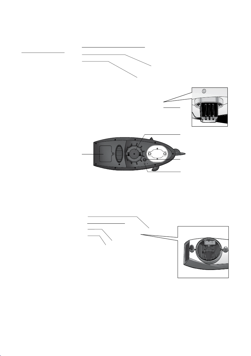
Main Console
1. Wi-Fi/SENSOR
2. REFRESH/UPLOAD
3. 6-in-1 Wireless Outdoor Sensor status LED
4. Wireless Indoor Sensor status LED
5. Status LED
6. RESET
7. USB socket
(for firmware update only)
8. Power jack
3 of 12
Page 4
Overview (continued)
6-in-1 Wireless Outdoor Sensor
1. Wind vane
2. Wind cups
3. Antenna
4. Louvre shield
5. Pole mount
(fit 35~40mm
pole, not included)
6. Hygro-Thermo
sensor
7. Batter y door
8. RESET
9. Transmission
status LED
10. Level gradienter
11. Rain collector
12. UV sensor
13. Solar panel
1
2
3
4
6
6
5
7
8
9
10
11
12
13
4 of 12
Page 5

Installation and Setup
MOUNTING ON POLE OR POST
MOUNTING POLE
MIN 1.5m
6-in-1 Wireless Outdoor Sensor
The 6-in-1 Wireless Outdoor Sensor
measures Wind-Speed, Wind-Direction, Rainfall,
UVIndex, Temperature and Humidity.
Pairing the 6-in-1 Wireless Outdoor Sensor
with the Main Console:
1. Unscrew the battery door at the bottom of the
6-in-1 Wireless Outdoor Sensor and insert
the batteries according to the polarity information
marked on the battery compartment.
2. Screw on tightly.
3. Once the batteries are installed, the
transmission status LED will begin to flash.
Ensure the battery door screw is locked well.
Ensure the transmission status LED
is flashing every 12 seconds.
Installing the wireless outdoor sensor:
Install the wireless outdoor sensor in an open
location with no obstructions above and around the
sensor for accurate rain and wind measurement.
Mounting guideline:
AND STAND
NOT INCLUDED
1. Install the 6-in-1 Wireless Outdoor Sensor
at least 1.5m off the ground for better and
more accurate wind measurements.
2. Choose an open area within 150m
from the Main Console.
3. Install the 6-in-1 Wireless Outdoor Sensor
as level as possible to achieve accurate rain
and wind measurements. Use the level indicator
on the top to ensure a level installation.
4. Mount the 6-in-1 Wireless Outdoor Sensor
with the solar panel end pointing to North to
correctly orient the direction of the wind vane.
To insure a tight grip, apply the rubber pads
provided before fastening the mounting
base to the pole or post (not included).
N
ADD RUBBER PADS BEFORE
5 of 12
Page 6

Installation and Setup (continued)
Main Console
Powering up the Main Console:
1. Plug the adaptor into the DC jack.
2. Once the power is connected, the
Main Console status LED will be in red
and after few seconds, it will show the Wi-Fi
connection status of the Main Console:
If the Main Console hasn't connected to the router
before, it will enter AP (Access Point) Mode
and the status LED will turn to green.
If the Main Console has connected to
the router before, it will try to reconnect
and the status LED will flash blue.
The Main Console LED can show the following:
Red light, solid: Start up
Green light, flashing: AP Mode
Blue light, solid: Connected to Wi-Fi
Blue light, flash: Searching for Wi-Fi
Red light, flash: Firmware update
Purple light, flash: Data refreshing
The Main Console can back up the router and
weather server settings. The wireless sensor
connection status is also stored here.
Wi-Fi connection status: As soon as the
Main Console successfully connects to the Wi-Fi
router, the status L ED will change to blue. If the Wi-Fi
signal is not stable or the Main Console is trying to
connect to the router, the status LED will flash blue.
During AP Mode the status L ED will flash green.
To search for the 6-in-1 Wireless Outdoor Sensor:
The Main Console will automatically search and
connect to the 6-in-1 Wireless Outdoor Sensor.
You can also press Wi-Fi/SENSOR to search for
it manually. Once they are paired successfully,
the sensor status LED will turn to blue.
Wireless outdoor sensor status LED:
Blue light, flash Searching for sensor
Orange light: Low battery
Light off: No signal for over 48hrs
Wi-Fi Connection Setup
To connect the Aspect Wi-Fi Solar to Wi-Fi, it
must be registered with Weather Underground.
Weather Underground setup instructions
are correct as of January 2019. Refer to
https://www.wunderground.com/ for details
if their registration process has changed.
6 of 12
Register with Weather Underground:
1. Visit https://www.wunderground.com/ and click
JOIN in the top right corner and follow the prompts
to create an account. Note that your email address
must be validated by Weather Underground before
proceeding. If you already have an account with
Weather Underground you can simply LOG IN.
Page 7

Installation and Setup (continued)
Wi-Fi Connection Setup
2. After logging in to your account, click MYPROFILE
and select MYWEATHERSTATIONS in the menu.
On the following page, click ADDANEWPWS.
On the next page, note it is essential to jot down
the LONGITUDE/LATITUDE for your reference later.
3. After noting the LONGITUDE/LATITUDE, follow
the prompts to complete registration of the
Aspect Wi-Fi Solar with Weather Underground.
After submitting your details, note it is
essential to jot down your STAT IO N ID
and STATION K EY/PA SSWORD.
Connect Main Console to Weather Underground:
4. Plug the adaptor into the DC jack to power up the
Main Console for initial star t-up. The status LED
will flash green to signify it has entered AP Mode.
You can also access AP Mode by holding
Wi-Fi/SENSOR for 6 seconds in Normal Mode.
5. Use your Wi-Fi enabled device to connect to
the Main Console SSID: PWS-XXXXXX.
6. Once connected, open the web browser
on your device, type 19 2 .16 8.1.1 into the
address bar and press ENTER to access
the Main Console setup interface.
7. Fill in the connection information (see below)
for the setup interface. The Main Console
will use this to connect your Wi-Fi router.
Interface will differ depending on your web browser.
8. Select the time zone, which is based on
the location of your Main Console.
7 of 12
Page 8

Installation and Setup (continued)
Barometric Pressure Setup
Barometric Pressure: Or atmospheric pressure, the
pressure at any location of the Earth caused by the
weight of the column of air above it. One atmospheric
pressure refers to the average pressure and gradually
decreases as altitude increases. Meteorologists use
barometers to measure atmospheric pressure.
Absolute Pressure: Absolute atmospheric
pressure of your location.
Relative Pressure: Relative atmospheric
pressure base on sea level.
Setting Relative Atmospheric Pressure Value:
1. Obtain the atmospheric pressure data of the sea
level (it is also the relative atmospheric pressure
data of your home area) through the local weather
service, internet or any weather information source.
2. In setup interface, select required pressure
unit and enter the relative pressure value.
The built-in barometer detects the absolute
atmospheric pressure and show on the
setup interface for your reference.
The relative atmospheric pressure is based on the
sea level pressure you entered but it will still change
with the absolute atmospheric pressure change.
Set UV Index Gain
The UV sensor manufacturer may have included a
gain or adjustment for a specific sensor technology or
build. Please reference your 6-in-1 outdoor weather
sensor battery compartment for any reference to
gain adjustment. In the below example, a gain of
1.7 must be entered into the Main Console.
In Main Console setup
interface, enter the
desire UV magnification
factor at the blank of
UV gain section.
Pointing 6-in-1 Wireless Outdoor Sensor to South
The 6-in-1 Wireless Outdoor Sensor is calibrated
to point to Nor th for the maximum accuracy. However,
for users in the Southern hemisphere, it is possible to
use the sensor with the wind vane pointing South .
1. Install the 6-in-1 Wireless Outdoor Sensor
with the wind meter end pointing South.
2. In the web browser setup interface, select S
in the Point Outdoor Sensor section.
8 of 12
Viewing Live Weather Data
1. To view live data from the wireless
outdoor sensor in a web browser, visit
https://www.wunderground.com/, and enter
your STATION ID & KEY in the search box.
Weather information will show on the next page.
Page 9

Maintenance
Cleaning the Rain Collector
1. Unscrew the rain collector by turning it 30°
anti-clockwise.
2. Gently remove the rain collector and clean and
remove any debris or insects.
3. Install the collector when it is clean and fully dried.
Cleaning the Outdoor Thermo-Hygro Sensor
1. Remove the two screws at the
bottom of the louvre shield.
2. Gently pull out the shield and carefully remove
any dirt or insects on the sensor casing
(do not let the sensors inside get wet).
3. Clean the shield with water to
remove any dirt or insects.
4. Install all the parts back when they
are clean and fully dried.
Cleaning the UV Sensor and Calibration
Cleaning the UV sensor cover lens
For precise UV measurement, gently clean
the UV sensor cover lens with water.
UV Sensor Degradation
Over time, the UV sensor will naturally degrade. The UV
sensor can be calibrated with a utility grade UV meter.
Main Console Firmware Update
1. Unzip the Update.zip file and copy the
unzipped Update folder to a USB drive.
Use a USB drive which is in FAT32
format. The Update folder must be in
the root directory of the USB drive.
2. Disconnect the Main Console DC power from
the power outlet. Plug the USB drive to the USB
socket on the back of the Main Console.
3. Reconnect the Main Console DC power to star t the
firmware update process. During the update process
the status L ED on the bottom side will flash red.
4. Once the update is complete, the Main Console
will restart and the status LED will return to blue
and connect to your previous connected router.
5. Remove the USB from the Main Console.
The USB port is for firmware update only.
Please keep the power on and do not press any
button during the firmware update process.
During the update process, do
not remove the USB drive.
If the firmware update does not start, you can try to
press the reset key to trigger the update process.
During the firmware update process, Wi-Fi
will be disabled until the update completes.
It will reconnect to your Wi-Fi router
and upload the data automatically. If the
Main Console cannot connect to your router,
you will need to re-enter the router and
Weather Underground connection information.
9 of 12
Page 10

Maintenance (continued)
Precautions
Read and keep these instructions.
Do not subject the unit to excessive
force, shock, or dust.
Do not cover the ventilation holes with any
items such as newspapers, curtains etc.
Do not immerse the unit in water. If you spill liquid
over it, dry it immediately with a soft, lint-free cloth.
Do not clean the unit with abrasive
or corrosive materials.
Do not tamper with the unit’s internal
components. This will void the warrant y.
Only use fresh batteries. Do not
mix new and old batteries.
Only use attachments/accessories
specified by the manufacturer.
Images shown in this manual may
differ from the actual display.
Placement of this product on certain types of
wood may result in damage to its finishing for
which manufacturer will not be responsible.
The contents of this manual may not be reproduced
without the permission of the manufacturer.
When replacement parts are required, be sure
the service technician uses replacement parts
specified by the manufacturer that have the
same characteristics as the original parts.
Unauthorised substitutions may result in
fire, electric shock, or other hazards.
Do not dispose old batteries as unsor ted
municipal waste. Collection of such waste
separately for special treatment is necessary.
The socket outlet shall be installed near the
equipment and shall be easily accessible.
Technical specifications and user manual contents
for this product are subject to change without notice.
Place the Main Console at least
20cm from nearby persons.
10 of 12
Page 11

Specications
Main Console
General
Dimensions (W×H×D) 79 × 157 × 41mm
Weight 130g
Main power DC 5V 1A adaptor
Weather data Barometric pressure
Operation range - 5˚C ~ 50˚C
Wi-Fi Communication
Wi-Fi standard 80 2.11 b/ g/n
Wi-Fi operating
frequency
Supported device
for setup U I
Recommended web
browser f or setup U I
Wireless Sensor Side Communication
Support sensors 1 Wireless 6-in-1 weather outdoor sensor
RF frequency
RF tran smissio n range 150m
Time
Time synchronise
method
Hour offset +12 ~ -12 hour
Barometer
Measuring range
Accuracy
Resolution 1hPa/0.01inHg/0.1mmHg
Outdoor Temperature
Measuring range -40 ~ 60°C (-40 ~ 140°F)
Accuracy
Resolution 0.1°C/0.1°F
2.4GHz
Built-in Wi-Fi with AP M ode function
smart devices, laptops or deskto ps:
Android smart phone, Android pad,
iPhone, iPad or Windows laptop
Web browsers that support HTML 5
(Chrome, Safari, IE, Edge, Firefox, Opera)
915Mhz (US version)/868Mhz (EU or
UK version)/917Mhz (AU version)
Through Internet time server
to synchronise the UTC
540 ~ 1100hPa (relative setting
range 930 ~ 1050hPa)
(700 ~ 1100hPa ± 5hPa)/
(540 ~ 696hPa ± 8 hPa)
(20.67 ~ 32.48inHg ± 0.15inHg)/
(15.95 ~ 20.55inHg ± 0. 24inHg)
(525 ~ 825mmHg ± 3. 8mmHg)/
(405 ~ 522mmHg ± 6mmHg)
Typical at 25°C (77°F)
-20 ~ 10°C ± 1.3°C
(-4 ~ 50°F ± 2.3°F)
-40 ~ -20°C ± 1.9°C (-40 ~ -4°F ± 3.4°F)
Outdoor Humidity
Measuring range 1 ~ 99%
Accuracy
Resolution 1%
Wind Speed and Direction
Measuring range 0 ~ 112mph, 50m/s, 180km/h, 97knots
Resolution 0.1m ph, 0 .1m/s , 0 .1km/h , 0.1k no ts
Speed accuracy ±2.2 mph or ±10% (whichever is greater)
Wind dire ction
resolutions
Rain
Accuracy for rainfall ± 7%
Range for rainfall 0 ~ 19999mm (0 ~ 787.3 in)
Resolution 0.254mm (0.01in)
UV
UV index r ange 1 ~ 16
1 ~ 90% RH ± 2.5% RH @ 25°C (77°F)
90 ~ 99% RH ± 3. 5% RH @ 25°C (77°F)
1º
Wireless 6-in-1 Outdoor Sensor
General
Dimensions (W×H×D) 392.5 × 326 × 14 4.5 mm
Weight 1096g (with batteries)
Main power
Auxiliary powe r Solar panel
Weather data
RF tran smissio n range 150m
RF frequency 915Mhz (US )/868Mhz ( EU, UK)/917Mhz (AU)
Transmission interval
Operation range
3 × AA size 1.5V batteries
(Alkaline batteries recommended)
Temperature, Humidity, Wind speed,
Wind direction, Rainfall and UV index
12 seconds for wind spe ed and wind direction
data 24 seconds for tem perature, humidity, UV
and rain data
-40 ~ 60°C (-40 ~ 140°F)
Lithium batteries required
Weather U ndergro und is a registered tr ademar k of The Weat her
Channel, L LC. both in the Uni ted Sta tes and int ernationally. The W eather
Underground Logo is a trademark of Weather Underground, LLC.
11 of 12
Page 12

Should you have any questions about this product or its operation
please telephone our customer service helpline on 1300 716 188.
Head Office/Service
11 Walters Drive, Osborne Park WA 6017
Ph: +61 8 9416 9999 Fax: +61 8 9416 9920
service@holmanindustries.com.au
www.holmanindustries.com.au
Copyright 2019 Holman Industries
 Loading...