

Page 1
®
®
®®®
GAS
CONVEYOR OVEN
MODEL
UM1854-NATCE
Installation and
Operation
Instructions
2M-Z6832 Rev. i 8/25/2011
UM1854
Page 2

2
These symbols are intended to alert the user to the presence of
important operating and maintenance instructions in the manual
accompanying the appliance.
RETAIN THIS MANUAL FOR FUTURE REFERENCE
NOTICE
Using any part other than genuine Star factory supplied parts relieves the
manufacturer of all liability.
Star reserves the right to change specifi cations and product design without
notice. Such revisions do not entitle the buyer to corresponding changes,
improvements, additions or replacements for previously purchased
equipment.
Due to periodic changes in designs, methods, procedures, policies and
regulations, the specifi cations contained in this sheet are subject to change
without notice. While Star Manufacturing exercises good faith efforts to provide
information that is accurate, we are not responsible for errors or omissions
in information provided or conclusions reached as a result of using the
specifi cations. By using the information provided, the user assumes all risks in
connection with such use.
MAINTENANCE AND REPAIRS
Contact your local dealer for service or required maintenance. Please record the model number, serial
number, voltage and purchase date in the area below and have it ready when you call to ensure a faster
service.
SAFETY SYMBOL
Model No.
Serial No.
Voltage
Purchase Date
Page 3
SPECIFICATIONS
UM1854-NATCE
Gas Rating/Connection: 11.72kW (40,000 BTU/hr), 1/2" BSP female pipe connection
Country: AT, DK, FI, IE, HU, PT NL LU, DE BE, FR
ES, SE, GB, IT, CH, CR
Gas Category: I2H I2L I2E 12E+
Pressure (mBar): G20@20 G25@25 G20@20 G20@20/25
Electrical Supply: 220-240v, single phase, 1.2A (max), 50Hz
Approximate Weight (Single Oven with Cart): Installed - 280 Lbs (127.27 kg), Shipping - 350 Lbs (159.09 kg)
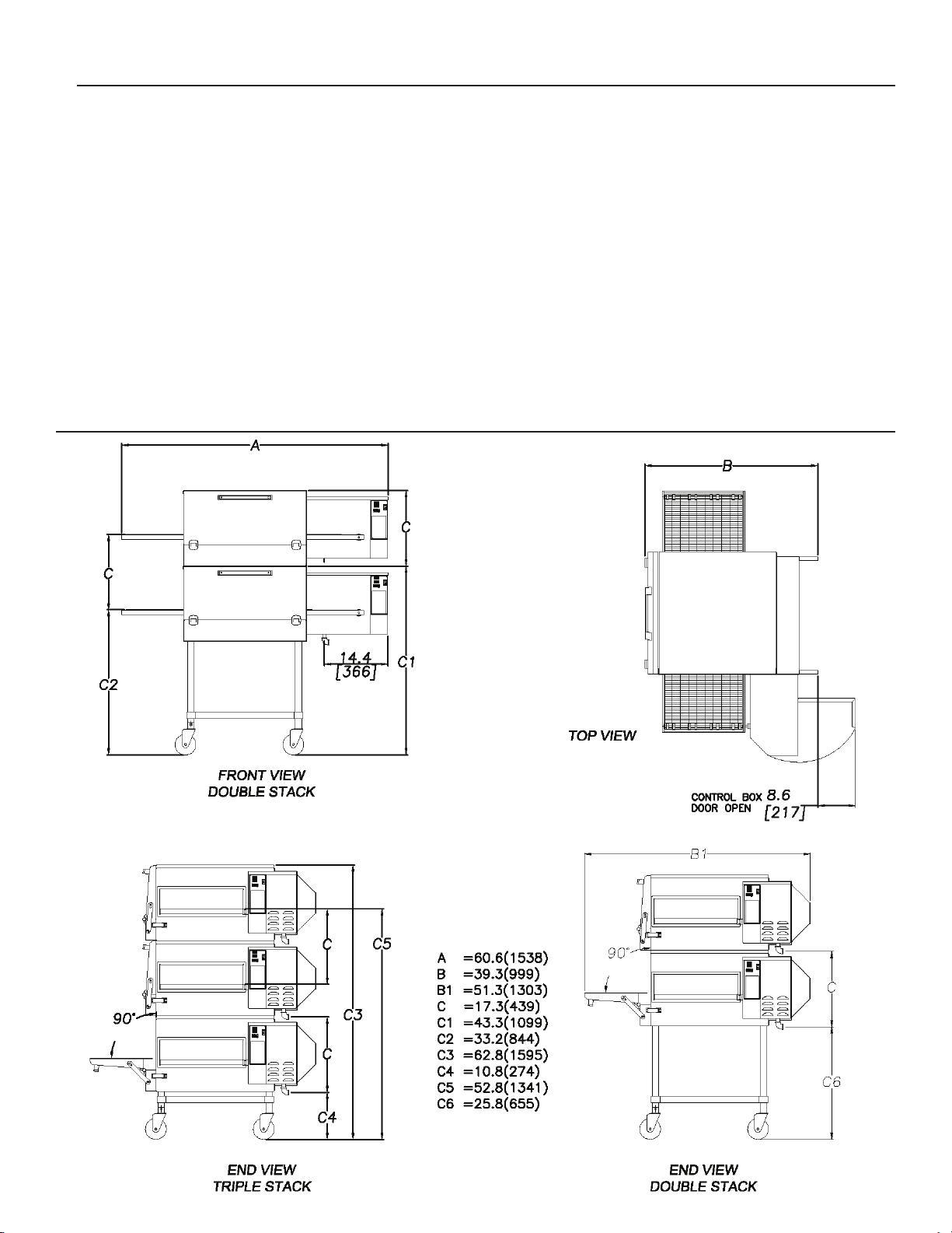
Dimensions: Width: 60.6" (153.9 cm)
Depth: 39.9" (99.82 cm) - Front Door(s) Closed
51.3" (130.3 cm) - Front Door(s) Open
Height: 43.3" (110.0 cm) - Single Oven with Stand
60.6" (153.9 cm) - Double Oven with Stand
62.8" (159.5 cm) - Triple Oven with Dolly
Recommended Minimum Clearances:
Rear of Oven to Wall 0" (0 cm)
3
Page 4
GENERAL INFORMATION
This equipment is designed and sold for commercial
use only by personnel trained and experienced in its
operation and is not sold for consumer use in and
around the home nor for use directly by the general
public in food service locations.
First and foremost, each crate should be examined
before signing the Bill of Lading to report any visible
damage by the trucker in transit and to account for the
proper number of crates. If there is apparent damage,
arrangements should be made to le a claim against the
carrier
the claim must be initiated by the consignee. Proper
and secure storage facilities should be arranged for
the oven(s) if necessary to protect it from outdoor or
damp conditions at all times before installation.
-IMPORTANT-
When you have all the crates unloaded, open the
crates and remove all plastic covers. Inspect at once
for concealed damage. If anything appears to be
damaged, contact the appropriate persons immediately
to le a damage claim. After completing this inspection,
nish unpacking the oven. Be sure to remove all paper
protection and packing material from the unit prior to
lighting.
CAUTION
. Interstate Commerce Regulations require that
NOTICE
This appliance must be installed with a stand and
casters designed by Star Manufacturing as part of a
complete installation. The installation must also include
a connector complying with either ANSI Z21.69 or CAN/
CGA-6.16 and a quick-disconnect device complying
with either ANSI Z21.41 or CAN1-6.9. It must also
be installed with restraining means to guard against
transmission of strain to the connector as specied in
the appliance manufacturer's instructions.
For your protection, we recommend a qualied
installing agency install this appliance in
accordance with the rules in force within
the country of destination. They should be
familiar with gas installations and your local
gas requirements. In any case, your gas
company should be called to approve the nal
installation.
This appliance, its pressure regulator, and its individual
shutoff valve must be disconnected from the gas supply
piping system during any pressure testing of that system
at test pressures in excess of 1/2 PSIG. This appliance
and its pressure regulator must be isolated from the gas
supply piping system by closing its individual manual
shutoff valve during any pressure testing of the gas
supply piping system at test pressures equal to or less
than 1/2 PSIG.
FOR YOUR SAFETY DO NOT STORE OR USE
GASOLINE OR OTHER FLAMMABLE VAPORS
AND LIQUIDS IN THE VICINITY OF THIS OR
ANY OTHER APPLIANCE.
The installation of the Appliance must conform to
"ANSI Z223.1 - LATEST EDITION" AND ALL LOCAL
GAS COMPANY RULES AND REGULATIONS.
IN CANADA INSTALLATION SHALL BE IN
ACCORDANCE WITH THE CURRENT CAN/CGAB149.1 NATURAL GAS INSTALLATION CODE OR
CAN/CGA-B149.2 PROPANE INSTALLATION CODE
AND LOCAL CODES WHERE APPLICABLE.
PURCHASER'S RESPONSIBILITY
It is the responsibility of the purchaser:
1. To see that the gas and electric services for
the oven are installed on site in accordance
with the manufacturer's specications.
2. To unload, uncrate, and install the oven in its
proper location and in accordance with this
installation operation manual.
3. To see that all gas and electric services are
connected properly by a qualied installer
of your choice. All such connections must
be in accordance with applicable code
requirements.
4. To arrange for inspection and operation checkout by an authorized service technician. The
warranty becomes effective upon verication
of proper installation.
4
Page 5
IMPORTANT SAFETY INFORMATION
Do not attempt to operate the oven until connection of
utility service has been fully inspected by an authorized
service technician or a Star Service Representative.
This service is required by Star in order to assist the
purchaser in proper start-up of the oven on site. Please
note the specic details on the Warranty and make
certain
utility services.
The warranty shall not apply if the oven is started
up and operated prior to the utilities and oven being
inspected and check-out made by an authorized service
technician or a Star Service Representative.
that service connections are made to proper
CAUTION
IMPROPER INSTALLATION, ADJUSTMENT,
ALTERATION, SERVICE, OR MAINTENANCE
CAN CAUSE PROPERTY DAMAGE, INJURY,
OR DEATH. READ ALL INSTRUCTIONS
THOROUGHLY BEFORE INSTALLING OR
SERVICING THIS EQUIPMENT.
CAUTION
Post in a prominent location the emergency telephone
number of your local gas supplier and instructions to
be followed in the event you smell gas. If the smell
of gas is detected, immediately call the emergency
phone number of your local gas company. They will
have personnel and provisions available to correct
the problem.
CAUTION
It is required that the oven be placed under a
ventilation hood to provide for adequate air supply
and ventilation.
CAUTION
Adequate clearance for air openings to the combustion
control chamber on the right side of the oven is required.
Do not obstruct the ventilation holes in the control panels
as these provide the combustion air for the burner and
cooling air for the controls.
CAUTION
The oven is to be operated only on the type of gas
and electricity shown on the specication plate. The
burner will not operate and gas will not ow through
the burner without electric power.
INSTALLATION INFORMATION
THE INSTALLATION INSTRUCTIONS
CONTAINED HEREIN ARE FOR THE USE OF
QUALIFIED INSTALLATION AND SERVICE
PERSONNEL ONLY. INSTALLATION OR
SERVICE BY OTHER THAN QUALIFIED
PERSONNEL MAY RESULT IN DAMAGE TO THE
OVEN AND/OR INJURY TO THE OPERATOR.
Qualied installation personnel are individuals, a rm,
a corporation, or a company which either in person
or through a representative are engaged in and
responsible for:
1. The installation or replacement of gas piping and
the connection, installation, repair, or servicing of
equipment.
2.
The installation of electrical wiring from the electric
meter, main control box, or service outlet to the
electric appliance.
Qualied installation personnel must be experienced in
such
work, familiar with all precautions required, and
have complied with all requirements of state or local
authorities having jurisdiction.
CAUTION
Minimum clearances must be maintained from all walls
and combustible materials. Minimum clearances for
this unit should be 0 inches from the rear (rear bumpers
provided must be in place) and 6 inches from both
sides. Keep the oven free and clear of all combustible
material.
5
Page 6
LOCATION
The well-planned and proper placement of your oven
will result in long-term operator convenience and
satisfactory performance.
NOTE:
usually be accomplished within the limited movement
provided by the gas hose restraint. If the oven needs
to be moved further from the wall, the gas must rst
be
removing the restraint. Reconnect the restraint after
the oven has been returned to its regular position.
It is essential that an adequate air supply to the oven
be maintained to provide a sufcient ow of combustion
and
1. Place the oven in an area that is free of drafts.
2. Keep the oven area free and clear of all combustibles
3.
4. On all models, tripping of the blower motor's thermal
On gas conveyor ovens, routine servicing can
turned off and disconnected from the oven before
ventilation air. Follow these guidelines:
such as paper, cardboard, ammable liquids, and
solvents.
Do not place the oven on a curb base or seal to a
wall. This will restrict the ow of air and prevent
p
roper ventilation to the blower motors. This
condition must be corrected to prevent permanent
damage to the oven.
overload device indicates an excessive ambient
temperature at the back of the oven. This condition
must be corrected to avoid permanent damage to
the oven.
CAUTION
VENTILATION
A VENT IS REQUIRED: Local codes prevail. These
are the "authority having jurisdiction" as stated by the
National Fire Protection Association, Inc. in NFPA
96-Latest Edition. For further ventilation information
see below.
A ventilation hood is required to remove heat and
cooking odors. For gas ovens, a ventilation hood is
also required to remove the products of combustion.
The hood and HVAC installation must meet local codes
to gain approval by the authority having jurisdiction.
Requirements may vary throughout the country
depending on the location by city, county, and state.
Obtain information from the authority having jurisdiction
to determine the requirements for your installation.
Obtain information and review copies of codes or
documents that will be used to inspect and approve your
installation. Your ventilation hood supplier and HVAC
contractor should be contacted to provide guidance.
A properly engineered and installed ventilation hood
and HVAC system will expedite approval and reduce
oven maintenance costs. Proper ventilation is the
responsibility of the oven's owner.
The ventilation hood must operate in harmony with the
building HVAC system. It typically requires between
750 and 2500 CFM exhaust. (The efciency of various
hood
designs makes it necessary to specify such a
wide range of ventilator CFM.) Make-up air must be
supplied by either a hood design or the HVAC system
to avoid a negative pressure condition. This will vary
with hoods from various manufacturers.
Failure to properly vent the oven can be
hazardous to the health of the operator
and may result in operational problems,
unsatisfactory baking, and possible damage
to the equipment.
Damage sustained as a direct result of improper
ventilation will not be covered by the warranty.
CAUTION
Prevent airow through the cooking tunnel. Air
must NOT be directed onto the oven's front or
rear or to the sides of the cooking area.
6
Page 7
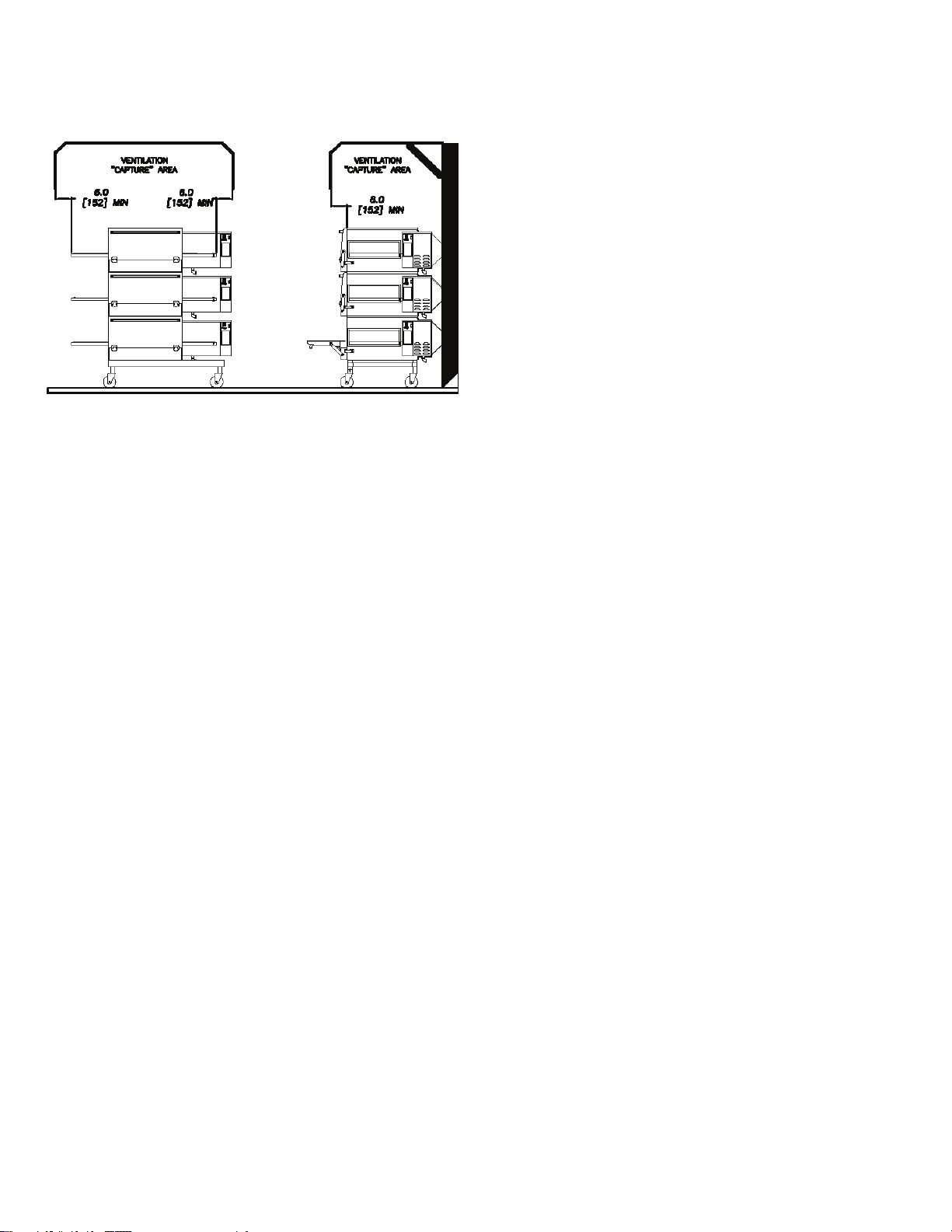
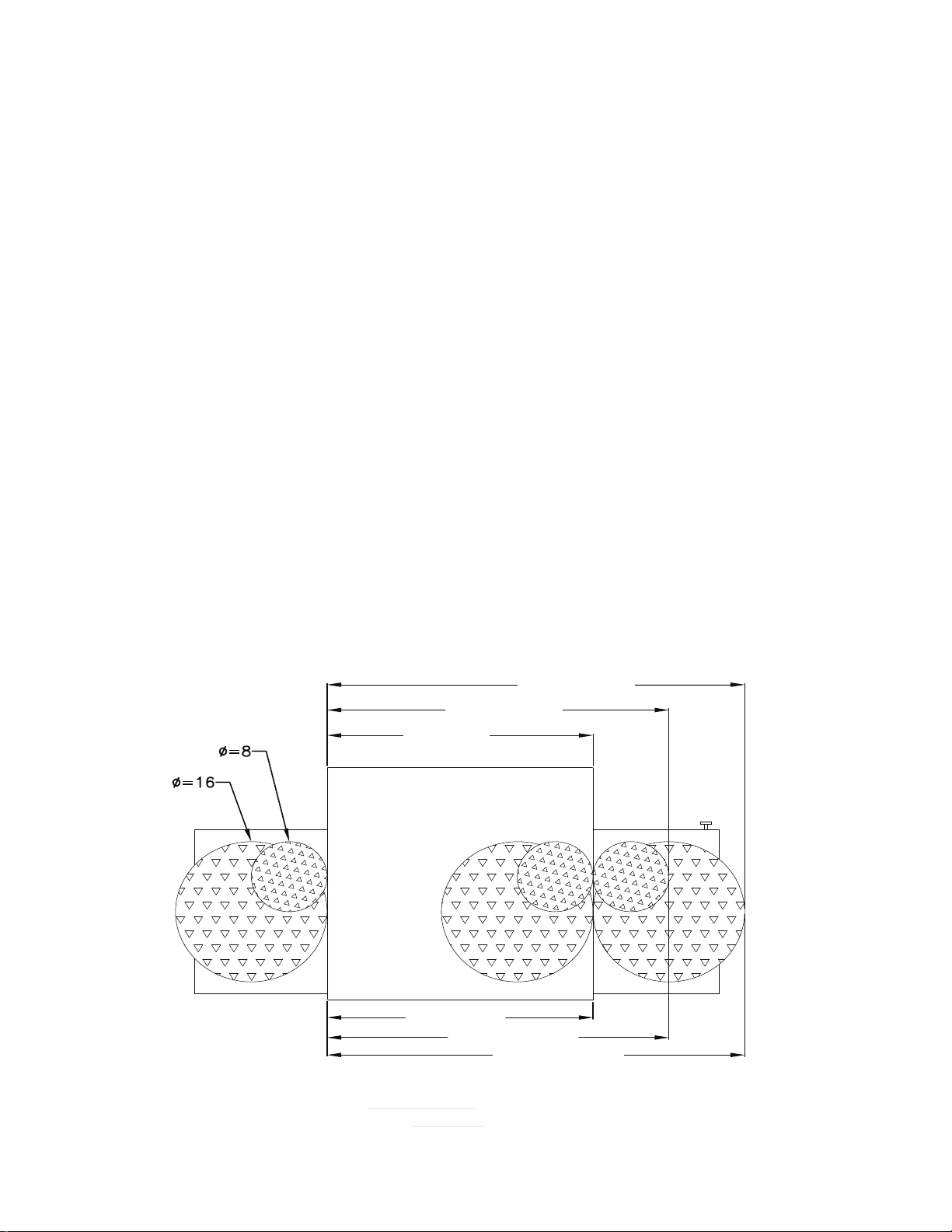
The following drawing shows a typical installation
and is intended to be a guideline. This is not a rigid
specication. Hood dimensions and positioning over
the oven will vary with hood manufacturer.
SMOKE CANDLE TEST
In order to verify the proper function of your ventilation
system, a smoke candle test should be done. If testing
a multiple oven system, this test should be done on
the bottom oven. The conveyor coupling should be
disconnected and the oven temperature must be set
and operating at a minimum of 480°F (249°C).
Test Procedure:
1. Wear heat-resistant gloves to prevent burns.
2. Put the smoke candle in an 8"x8"x2" cake pan.
3. Insert candle through conveyor tunnel or oven door.
(Use Star Smoke Candle 2W-Z5668.)
4. Light the fuse of the smoke candle and immediately
center the pan in the oven cavity on the conveyor
belt (keeping the oven door closed).
5. Observe the smoke pattern coming out of all oven
openings and the collection of this smoke by the
ventilation system.
6. All smoke from the oven must be captured by the
ventilation system.
GAS SUPPLY RATING AND SIZING
Calculations for pipe sizing must take into account
the maximum usage rate of all other appliances in the
kitchen or one or more of the appliances will suffer from
inadequate or dangerous performance. The 1/2" BSP
connection for the oven is generously sized for use
in the control box of the oven. However, unless the
oven installation is within 10 feet of the main building
gas supply, the supply must be larger. For each oven,
a 3/4" exible quick connect hose and full port gas
shut-of
main pipe supplying each oven branch may need to be
larger depending on the number of appliances serviced,
the number of elbows in the piping, and the pressure.
This should be sized and installed by a professional
familiar with any local codes that may also affect the
installation.
f valve is recommended as a MINIMUM. The
ACCESS CONSIDERATIONS
Locating the gas valve(s), quick connect hose(s) and
electrical outlet(s) at the control box end of the oven will
allow easier access for any service visits. This improved
access should make any necessary service quicker
resulting in less kitchen disruption. It will also allow
easier disconnection of electricity, gas, and restraints
for cleaning around and behind the oven.
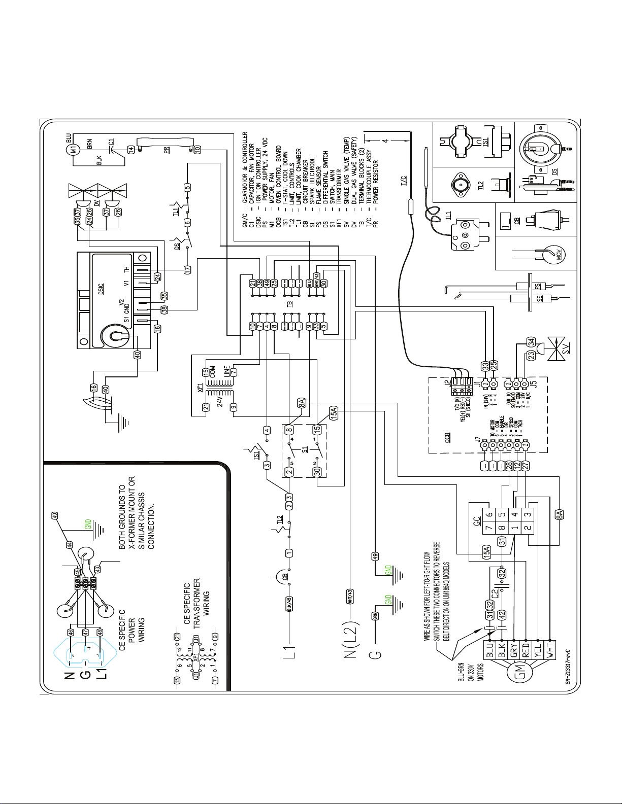
ELECTRICAL CONNECTION
Before making any electrical connections to this unit,
check that the power supply is adequate for the voltage,
amperage, and phase requirements stated on the rating
plate. A wiring diagram is included herewith.
When installed, this appliance must be electrically
grounded and its installation must comply with IEC
codes, manufacturer's installation instructions, and
applicable local municipal building codes.
PRESSURE REGULATION AND TESTING
Each oven is supplied with a regulator to maintain
the proper gas pressure. The regulator is essential
to the proper operation of the oven and should not
be removed. A pressure reading can be taken at the
9mm test port on the rear of the combination valve.
The reading should be taken while the oven is heating
up. The regulator is located on the bottom of the gas
combination valve, just inside the control box. There
is no need to install an additional regulator where the
oven connects to the gas supply unless the supply
exceeds the maximum.
NOTE: The supplied regulator is evaluated for a
maximum gas supply pressure of 14" water column
(34.5 mBar). The recommended maximum gas supply
pressure is 12" water column (29.9 mBar).
7
Page 8
Installation must conform with local codes or, in the
absence of local codes, with NFPA54/ANSI Z223.1
- Latest Edition.
CAUTION
During pressure testing note the following:
1. The oven and its individual manual shut-off valve
must be disconnected from the gas supply piping
system during any pressure testing of that system
at test pressures in excess of 1/2 psig (3.45 kPa).
Turn OFF main gas shut-off valve or main gas
supply line.
2. The oven must be isolated from the gas supply
piping system by closing its individual manual
shut-off valve during any pressure testing of the
gas supply piping system at test pressures equal
to or less than 1/2 psig (3.45 kPa).
3. If incoming pressure is over 14" water column, a
separate regulator for the oven must be installed
before the gas supply to the oven. It must
regulate pressure to 11" water column (27.1 mBar)
maximum.
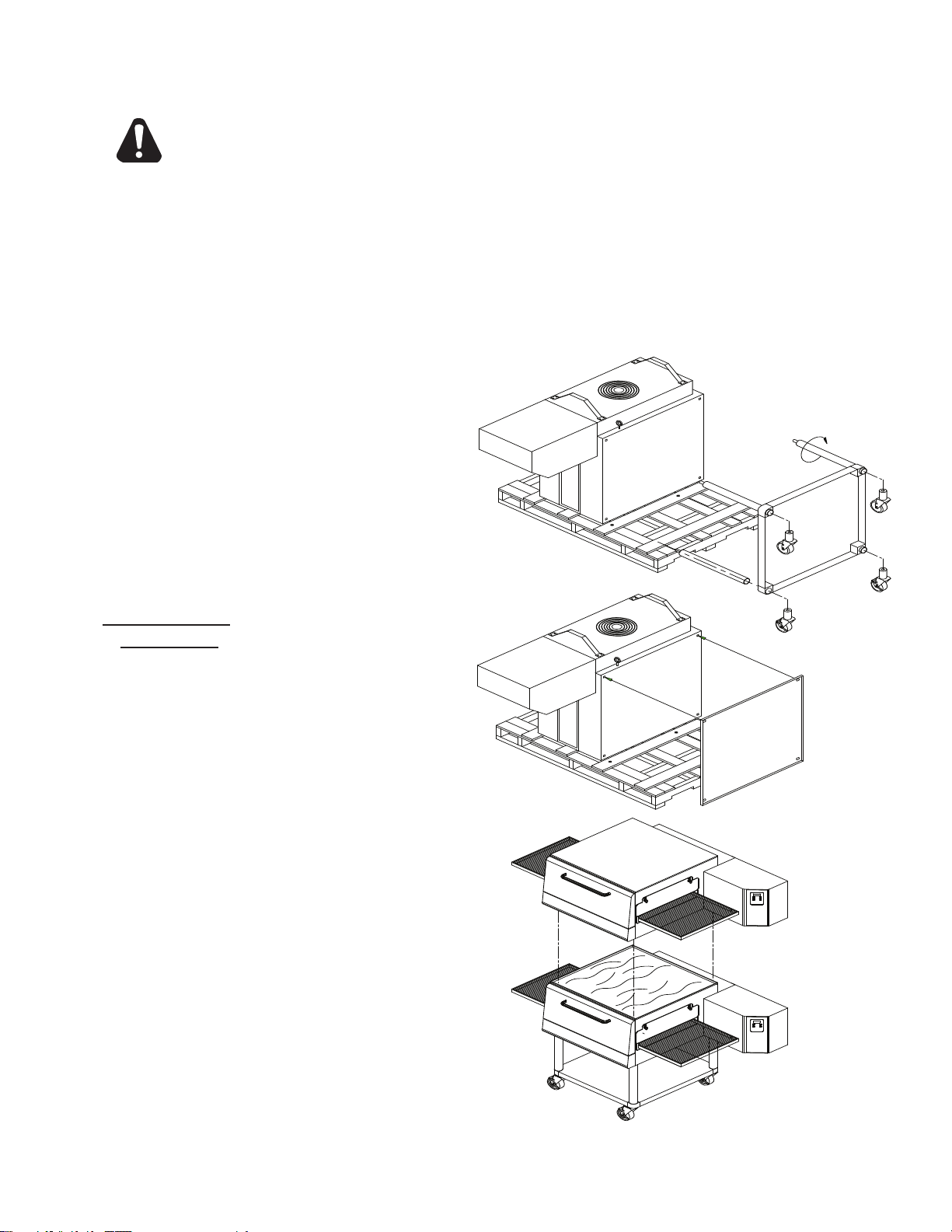
Stacked Oven Install Preparation:
1. Remove door, conveyor, and nger assemblies.
2. Unbolt unit from shipping crate (4 bolts).
3. Turn unit on front as shown.
4. Remove top of lower oven (4 screws total, 2 each
front and rear) and bolt to stacked oven base using
5/8 - 11 bolts (4 each, included).
5. Place top oven on lower unit and re-attach with
screws for top of lower oven.
6. Use restraint on lowest oven to prevent any high
loads that could tip the oven stack.
WARNING: To prevent damage to the control
valve regulator during the initial turn-on of gas,
it is very important to open the manual shut-off
valve very slowly. After the initial gas turn-on,
the manual shut-off valve must remain open
except during pressure testing as outlined in
the above steps or when necessary during
service maintenance.
STACKING INSTRUCTIONS
The following instructions should be followed when
stacking more than one unit.
Single Oven (or Bottom) Cart Install:
1. Remove door, conveyor, and nger assemblies.
2. Unbolt unit from shipping crate (4 bolts).
3. Turn unit on front as shown.
4. Slide legs into stand shelf and thread legs into
bottom of oven.
5. Install casters into bottom of legs. Place casters
with brakes to the front.
6. Position shelf as desired and fasten to legs.
7. CAREFULLY lift oven upright.
8
Page 9
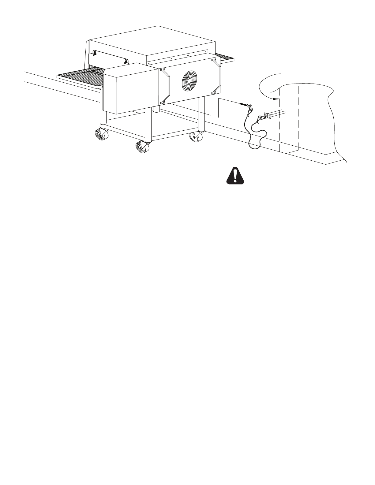
RESTRAINT REQUIREMENT
HOLLOW WALL STUD
OR MASONRY WALL
A
B
C
CAUTION
1. The installation shall be made with a gas connector
that complies with local codes for connectors for
movable gas appliances and a quick-disconnect
device that complies with local codes for such
devices in use with gas fuel.
2. The installation of the restraint must limit the
movement of the oven(s) without depending on
the connector, the quick disconnect device, or
associated piping to limit the oven movement.
3. If the restraint must be disconnected during
maintenance or cleaning, it must be reconnected
after the oven has been returned to its originally
installed position.
OPERATING INSTRUCTIONS
DO NOT ATTEMPT TO OPERATE THE OVEN until
connection of utility service and installation has been
fully inspected (start-up check-out) by an authorized
service technician or your dealer/distributor in order to
assure the oven is properly installed and in working
order. The warranty becomes effective upon
verication of proper installation.
DO NOT WORK AROUND THE CONVEYOR
BELT WITH LONG HAIR, LOOSE CLOTHING, OR
DANGLING JEWELRY. GETTING CAUGHT IN
THE BELT COULD RESULT IN DISMEMBERMENT
OR FATAL INJURY.
Unless specied otherwise, conveyor travel is factory
set for left to right operation when facing the front of
the oven. If a direction change is required, refer to
"DISPLAY INFORMATION," section 3 for instructions
on how to program the controller for a direction change.
In addition, the conveyor belt must be changed to travel
in the new direction.
SAFETY OPERATING INSTRUCTIONS
The information contained in this section is provided
for the use of qualied operating personnel. Qualied
operating
read the information contained in this manual, are
familiar with the functions of the oven and/or have
had previous experience with the operation of the
equipment described. Adherence to the procedures
recommended herein will assure the achievement of
optimum performance and long, trouble-free service.
personnel are those who have carefully
9
Page 10
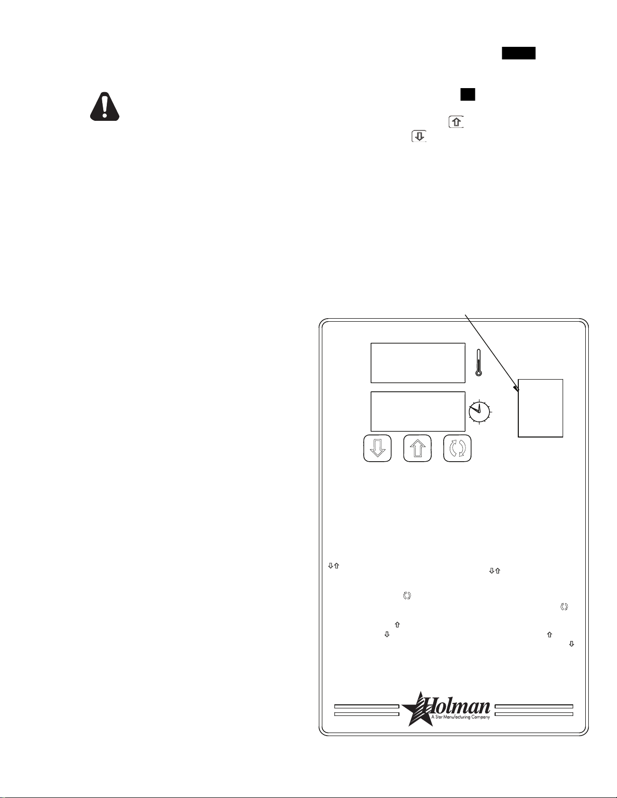
3) Press the up button ( ) to increase
or the down button ( ) to decrease
TIME or TEMPERATURE. Hold
button down for faster display
changes.
4) After five seconds, the new numbers
will be saved and the oven will display
new settings.
4) Après cinq secondes, les nouveaux
nombres seront sauvés et le four montrera
de nouveaux arrangements.
3) Tenez "vers le haut" bouton ( ) pour
augmenter ou "vers le bas" boutonnez ( )
pour diminution de le TEMPS ou
TEMPÉRATURE. Maintenez le bouton pour
des changements plus rapides.
1) Press the up and down buttons
( ) at the same time, hold for four
seconds until TIME display is blank.
2) Press the enter button ( ) to
switch between TIME and
TEMPERATURE.
Adjusting TIME and TEMPERATURE:
If burner does not light in one minute
push the power switch to the "OFF"
position and wait five minutes.
After five minutes, retry.
Push power switch "ON."
To Start:
2) Appuyez sur le bouton de "entrée" ( )
pour commuter entre le TEMPS et la
TEMPÉRATURE.
1) Tenez "vers le haut" et "vers le bas"
boutonne ( ) en même temps. Tenez
les boutons pendant quatre secondes
jusqu'à ce que l'affichage de la
TEMPS soit blanc.
Après cinq minutes, nouvelle tentative.
Si le brûleur n'allume pas en une minute,
poussée le commutateur de puissance dans
la position de "ARRÊTE" et attend 5 minutes.
Poussez le commutateur de puissance à
"MARCHE."
OFF / ARRÊTE
Ajustement du TEMPS et de la
TEMPÉRATURE:
Pour Commencer:
ON / MARCHE
SWITCH CUTOUT
IL1050
Please take time to read the following safety
operating instructions. They are the key to the
successful operation of your Ultra-Max Conveyor
Oven.
SAFETY TIPS
For your safety, read before operating.
If you smell gas:
1. DO NOT try to light any appliance.
2. DO NOT touch any electrical switches.
3. Use an exterior phone to call your gas supplier
immediately.
4. If you cannot reach your gas supplier, call the re
department.
In the event of a power failure:
1. Turn all switches off.
2. DO NOT attempt to operate the oven until the power
is restored.
NOTE: In the event of a shut-down of any kind, allow
a ve (5) minute shut-off period before attempting
to
restart the oven.
General Safety Tips:
To adjust the time and temperature:
1. Press the DOWN and UP arrows ( ) at the
same time. Hold for four seconds until the TIME
display goes blank.
2. Press the ENTER button (
) to switch between
TIME and TEMPERATURE.
3. Press the UP arrow (
DOWN arrow (
) to decrease the TIME or
) to increase or the
TEMPERATURE. Hold either button down for
faster display changes.
4. After ve seconds, the new numbers will be saved
and the oven will display the new settings.
To turn the oven off:
1. Push the power switch to "OFF." The oven is
equipped with a cool-down feature for motor shaft
and bearing protection. This enables the blower
motor(s) to run regardless of the controller status.
The blower(s) continue to run until the oven cools
to a safe temperature.
1. DO NOT use tools to turn off the gas control. If
the gas cannot be turned off manually do not try
to repair it. Call a qualied service technician.
2. If the oven needs to be moved for any reason, the
gas must be turned off and disconnected from the
unit before moving the restraint cable. Reconnect
the restraint after the oven has been returned to
its original location.
3. DO NOT remove the control box cover unless
theoven is unplugged.
OPERATION
To turn the oven on:
1. Push the power switch to "ON."
2. If the burner does not light in one minute, push the
power switch to the "OFF" position and wait ve
minutes.
3. After ve minutes, retry.
10
Page 11
DISPLAY INFORMATION
When operating the oven, there are three levels
of access:
1. Store Level - General employees would know these
functions and how to change them. While the oven
is running, enter this mode by holding the DOWN
and UP arrows (
seconds. The TIME display goes blank and the
TEMP setpoint is displayed. Adjust with the DOWN
or UP arrows. The ENTER button (
between TIME and TEMP. The parameter that can
be adjusted is displayed, the other is blank. When
TIME and TEMP are adjusted as needed, wait
ve seconds and SAVE is displayed. The values
are accepted and the controller begins controlling
to these new values. The conveyor continues to
operate at the same speed until a new value is
accepted. The temperature control output should
be OFF during changes.
2. Manager Level - This is a lock so that TIME and
TEMP cannot be changed even at the Store Level.
While the oven is running, enter this mode by
holding the DOWN and UP arrows simultaneously
for 4 seconds. The TIME display goes blank and
the TEMP setpoint is displayed. Release the
UP arrow and continue to hold the DOWN arrow
for an additional 4 seconds. The TEMP display
shows LOC as the TIME display shows nO, which
indicates that the TIME/TEMP parameters can be
changed
) simultaneously for four
) toggles
after reaching the STORE level. yES indicates
that the parameters cannot be changed even after
entering the STORE level. The LOC setting can
be toggled using the ENTER button (
).
ADDITIONAL FUNCTIONS
The conveyor belt direction and the temperature
display can be changed on the conveyor oven
by a qualied technician. To change the belt
direction, the technician must reverse the motor
direction and rotate the conveyor belt for proper
oven function. A technician can also change the
temperature display from Fahrenheit to Celsius.
These changes can be made by the technician
during the start-up/check-out or at a later date.
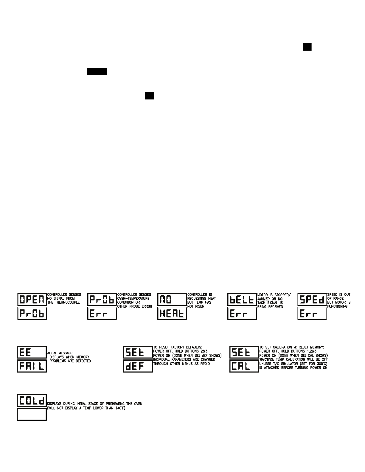
ERROR CODES
Error codes will display as ashing text messages for
diagnostic purposes. Any temperature or thermocouple
error should turn the temperature output OFF and leave
the conveyor running at the same speed. The belt error
should turn the temperature output OFF. The speed
error should display when the motor is unable to settle
at the chosen speed. This might occur if a fast speed
is chosen that the motor is unable to spin fast enough
to achieve. The speed signal output will remain the
same but the display will ash the error message.
11
Page 12
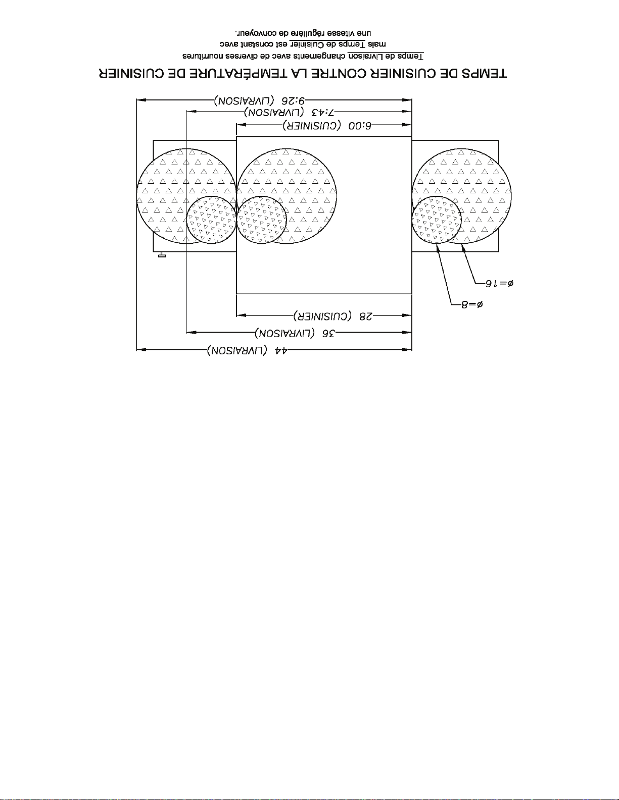
BAKE TIME VERSUS TEMPERATURE
BAKE vs. DELIVERY TIME
Time to Delivery changes with product
but
Bake Time remains constant
at a steady conveyor speed.
28 (BAKE)
36 (DELIVERY)
44 (DELIVERY)
6:00 (BAKE)
7:43 (DELIVERY)
9:26 (DELIVERY)
1. Bake time is actually conveyor speed and is dened
as the time the product is actually in the oven. This
is measured by noting the time when the leading
edge of the product enters the oven and the time
the leading edge of the product leaves the oven.
This is adjusted by using the conveyor speed
controller.
2. Bake temperature is adjusted by changing the
setpoint of the temperature controller to the desired
bake temperature. When the oven reaches the
desired temperature, the red dot in the lower right
corner of the temperature display will turn off and
on as the controller maintains the temperature.
3. When establishing a bake time and temperature
for a given product, the general rule shall be as
the bake time increases the bake temperature
decreases and the reverse is also true; increase
temperature, decrease time. However, there are
limits to the above rule. Going to extremes will result
in a burnt exterior and raw interior or it will result
in a very light color but over-baked product.
4. Once a good bake has been established, the ne
adjustments should be made by holding either
the bake time or bake temperature constant, then
varying the other.
CONVEYOR SPEED
Bake Time (Conveyor Speed) - As stated previously,
bake time (conveyor speed) is dened as the amount
of time elapsed between the time the leading edge of
the product enters the oven and the leading edge of
the product exits the oven. Bake time is controlled by
adjusting the digital speed controller. The setting on
the control panel indicates the actual bake time.
Bake time will be the same for any size product.
TIME OF DELIVERY
The time of delivery is the amount of elapsed time
between the period when the leading edge of the
product enters the oven and the trailing edge of the
product is fully discharged and is ready to be delivered
to the customer.
Time of delivery changes if the product size
changes.
Tip: Train yourself not to pull the product out of the
oven when the leading edge comes out. Always wait
until the entire product is out - the product needs this
time to fully bake.
12
Page 13

MAINTENANCE INSTRUCTIONS
Follow this recommended cleaning schedule for proper
oven performance:
CAUTION
DISCONNECT THE POWER SUPPLY BEFORE
SERVICING OR CLEANING THIS OVEN.
SAFEGUARD THE POWER SO IT CANNOT BE
ACCIDENTALLY RESTORED. FAILURE TO
DO SO COULD RESULT IN DISMEMBERMENT,
ELECTROCUTION, OR FATAL INJURY.
THERE IS MORE THAN ONE POWER SUPPLY
CONNECTION POINT WHEN OVENS ARE
STACKED, SO MAKE SURE THAT ALL
SWITCHES ARE IN THE OFF POSITION BEFORE
CLEANING OR MAINTENANCE.
No electrical components should be subjected to
moisture. It is therefore important that the oven is wiped
down carefully. NEVER throw buckets of water over
the oven or subject it to pressure washing from a hose
or a pressure spray. If water or other liquid is spilled
on the oven, make sure that none of it has entered the
control box area before switching the oven ON. If in
doubt, call your service company.
CAUTION
Adhere to the following warnings when cleaning or
maintaining your gas conveyor oven:
1. The oven must be cool. Do not use power cleaning
equipment, steel wool, or wire brushes on stainless
steel surfaces.
2. Do not use a caustic or an alkaline base cleaner on
the interior of the oven. This will ruin the aluminized
nish of the oven interior.
3.
When using cleaning solutions, be sure they meet
local and national health standards.
DAILY
1. Clean the conveyor belt using a nylon brush. Allow
any foreign material to drop into the crumb pans.
2. Empty and clean the crumb pans. Use a hot water
and detergent mix. Rinse with clean water.
EVERY MONTH
1. Brush and clean the guard on the motor cooling
fan.
EVERY THREE MONTHS
1. Unplug the oven and disconnect gas
connections.
2. Remove the crumb pans.
3. Remove the conveyor assembly.
4. Unlatch and remove the front door. Remove all
internal airow components.
5.
Clean the oven interior with an appropriate oven
cleaner.
6. Clean the conveyor assembly, crumb pans, and
other removable components. Wash in a hot
water, detergent mix and rinse with clean water.
For difcult cleaning areas, use a heavy-duty de-
greaser or oven cleaner.
7. Move the oven and clean under it. Be careful not
to damage the oven's gas hose or electrical cords
when moving.
8. Reassemble the oven.
EVERY TWELVE MONTHS
A factory authorized service person should:
1. Open and clean the inside of the control box.
2. Check and tighten all electrical components.
If maintenance is required, contact your local
service company, a factory representative, or Star
Manufacturing.
CAUTION
If the gas oven needs to be moved, the gas must be
turned off and disconnected from the unit before
moving the restraint. Reconnect the restraint
after the oven has been returned to its original
location.
13
Page 14

DIRECTIONS FOR DISASSEMBLY
1. Remove crumb trays and
shelves from both ends.
4. Finish removing the conveyor
assembly from the right end
of the oven.
2. Push the spring-loaded
coupling in to disengage the
pin in the shaft. Rotate the
shaft so the pin will not go
back in the coupling slots.
5. Upper nger assembly can
be removed complete or
the small handle (left) can
be used to slide nozzle and
columnating plate out before
removing the main body.
3. Lift up the left end of the
conveyor frame so the crumb
tray supports clear the tunnel
opening. Push the conveyor
frame through the tunnel
opening.
6. Upper nozzle (with slot) and
columnating plates (with tab).
Extruded holes all point in the
same direction (down toward
the conveyor).
7. The lower nger assembly can
be removed complete or the
nozzle can be slid off to reveal
the recessed columnating
plate.
8. The columnating plate also
has a slot that must align with
a tab on the nger to ensure
proper orientation. Extruded
holes point up toward the
bottom of the conveyor.
14
9. The oven body is now ready to
be wiped clean. Reassemble
the nger and conveyor parts
in the reverse order after
cleaning.
Page 15

CONVEYOR BELT TENSION
The conveyor belt of the Ultra-Max Gas Conveyor
Oven does not have a tension adjustment. If the belt
becomes too loose, a link will have to be removed to
tighten. A belt that is too tight will also cause operational
problems due to excessive drag. We suggest that
you have a qualied service technician perform this
adjustment.
CAUTION
Careful consideration should be exercised prior
to removing a belt link because a belt that is
too tight will impede the smooth operation of
the conveyor.
CONVEYOR BELT LINK REMOVAL
An entire link can be removed with the conveyor
assembly either in or out of the oven. This may be
necessary as the belt stretches after continuous
use. Following are the necessary steps for removing
links:
1. Move the splice clips to either end of the oven for
easy access.
2. Unhook the splice clips using long nose pliers.
3. Unhook the full link to be removed and slide it out.
Do not discard the link removed as it may be used
for making spare splice clips.
4. Reconnect the inside splice clips.
5. Reconnect the outside splice clips.
6. Replace all parts removed from the oven.
7. Straighten any bent wires to ensure smooth sprocket
engagement.
Remove the outside master links on the right and left
sides of the conveyor belt. Remove the center splice
clips next.
Unhook the end loop and pull up on the link section.
Save this link as it may be used for making splice
clips.
Check
should be up). The belt shown is the top section,
ready for left-to-right travel.
the orientation of the splice clips (the hooks
15
Page 16

INTERNATIONAL ONE (1) YEAR EQUIPMENT WARRANTY
All workmanship and materials in “STAR” products are warranted for a period of one year from the date shipped from the factory or
one year from the date shown on the proof of purchase of the end-user when purchased through an authorized “STAR” dealer/dis-
tributor in a commercial foodservice location.
“STAR’s” obligation under this warranty is limited to the replacement of the defective part(s) only without charge. This warranty is
void if damage occurs from improper installation, misuse or abuse, disassembly or tampering of unit for any purpose other than repair
by a qualifi ed service agent, wrong voltage, incorrect or fl uctuating voltage conditions, wrong gas, improper gas or gas conditions,
operated contrary to the installation and operating instructions, operated in an application for which the unit is not suited, or if the unit
is not maintained and/or cleaned in a suitable manner.
Any expense in connection with installation, or any cost of making adjustments on a unit to conform to electric or gas service at the
point of installation, are not covered by this warranty.
* The warranty period for the JetStar series six (6) ounce popcorn machines is two (2) years.
* The warranty period for the Chrome-Max Griddles is fi ve (5) years on the griddle surface. See detailed warranty provided with unit.
* The warranty period for Tefl on/Dura-Tec coatings is one year under normal use and reasonable care. This warranty does not
apply if damage occurs to Tefl on/Dura-Tec coatings from improper cleaning, maintenance, use of metallic utensils, or abrasive
cleaners. This warranty does not apply to the “non-stick” properties of such materials.
* This warranty is not valid on Conveyor Ovens
unless a “start-up/check-out has been performed by a Factory Authorized Technician.
In order to make a claim under this warranty; a warranty report must be fi led with Star Manufacturing International Inc. in St. Louis,
Missouri, U.S.A. by the dealer/distibutor through which product was purchased. All details, including serial number and model number of the defective unit, must be included. Failure to fi le a claim within a 120 Day time period may result in the claim being refused.
“STAR” may forego the necessity of returning the part for inspection dependent upon the expense involved. However, “STAR”
requires defective parts to be held in the claimant’s possession for a period of ninety (90) days for possible inspection by a “STAR”
representative or designated inspector .
The foregoing warranty is lieu of any and all other warranties, expressed or implied, and constitutes the entire warranty.
PARTS WARRANTY
Parts that are sold for out-of-warranty repair are warranted for a period of ninety days. The part only is warranted; no labor.
SERVICES NOT COVERED BY WARRANTY
1. Labor
2. Mileage and/or travel time
3. Installation and/or adjustment of equipment
4. Operation contrary to the installation and operating instructions
5. Cleaning of equipment
6. Seasoning of griddle plates
7. Voltage conversions/adjustments
8. Gas conversions
9. Pilot light conversion/adjustments
10. Thermostat calibration/adjustments
11. Resetting of circuit breakers or safety controls
12. Replacement of bulbs/lamps
13. Replacement of fuses
14. Damages due to improper installation
15. Damages from abuse or misuse
16. Damage created by acts of God, Acts of War, or Civil Disturbance
08-05 rms
Page 17
Page 18

1678 2345
1
8
10
29
36
26
23
22
25
27
21
24
23
13
20
17
18
16
15
14
3
4
6
9
5
7
11
12
19
31
32
2
34
33
37
38
39
40
35
41
THIS DRAWING CONTAINS INFORMATION CONFIDENTIAL TO STAR MANUFACTURING
INTERNATIONAL, INC. NO REPRODUCTION OR DISCLOSURE OF ITS CONTENTS IS
PERMITTED.
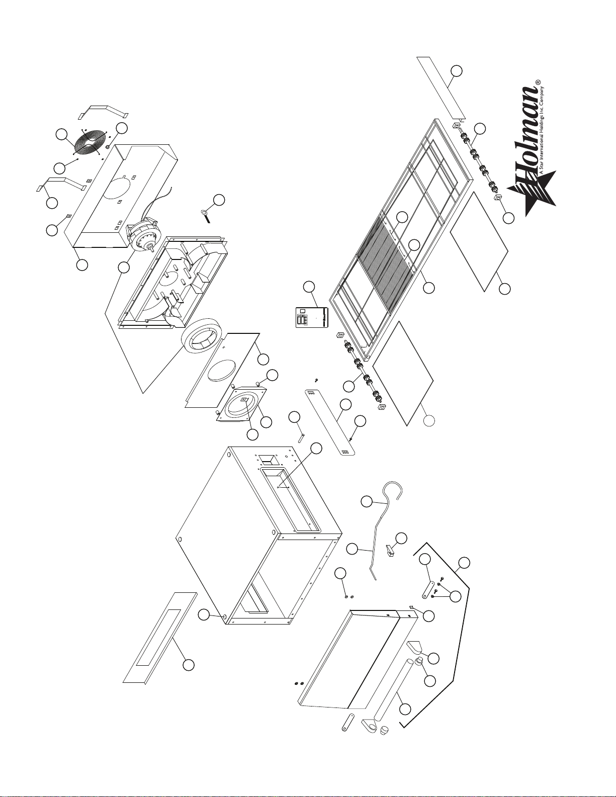
MODEL - UM1854-CE, CONTROL BOX ASSEMBLY
CERTAIN INSTANCES MAY NOT BE AVAILABLE
ILLUSTRATIVE PURPOSES ONLY AND IN
SOME ITEMS ARE INCLUDED FOR
SK2004 REV. - 8/22/03
Page 19

PARTS LIST August 25, 2011, Rev I
Ultra-Max Gas Conveyor Oven
UM1854-NATCE - Control Box
MODEL
Key
Number
1 G9-GC0013 1 CONTROL BOX DOOR
2 G9-Z6606 1 TIME & TEMP CONTROLLER (GAS OVEN, 230V)
3 G9-Z5250 1 POWER SUPPLY BRACKET
4 G9-Z5251 1 GEARMOTOR BRACKET
5 G9-Z5249 1 CONTROL BOX LID
6 2T-Z5175 1 THERMOSTAT, COOL DOWN, 120°F
7 2T-Z5176 1 THERMOSTAT, HI-LIMIT, 140°F
8 2T-Z5177 1 HIGH TEMPERATURE LIMIT
9 2E-Z5206 1 10AMP
10 2E-Z5683 1 VACUUM SWITCH
11 2E-Z1858 1 LIGHTED SWITCH
12 2E-Z5642 1 POWER RESISTOR
2E-Z5663 2 POWER RESISTOR BRACKETS
13 2J-Z5189 1 THERMOCOUPLE
14 G9-Z6610 1 POWER SUPPLY - 24VDC (230V INPUT), MANUFACTURED BEFORE OCT. 2010
15 2E-Z6828 1 TRANSFORMER
16 2E-Z11786 1 IGNITION CONTROL, OVEN
17 G9-Z5661 1 ELECTRODE SET
18 2U-Z5171 1 GEARMOTOR, 500:1, 24V, DC
2U-Z8629 1 GEARMOTOR, 240:1 230VAC
19 2A-Z5164 1 COUPLING
20 2F-Z5173 1 BURNER - NATURAL
G9-Z5670 1 #33 ORIFICE (HI NATURAL) (INCLUDED IN BURNER)
G9-Z5671 1 #56 ORIFICE (LO NATURAL) (INCLUDED IN BURNER)
21 2K-2667 1 PIPE ELBOW (NPT)
22 2K-Z3381 1 PIPE NIPPLE
23 2K-Z5105 1 COMPRESSION ELBOW
24 2K-Z5106 1 COMPRESSION ELBOW
25 2V-Z6825 1 GAS COMBINATION VALVE - NATURAL - 24VAC
26 2V-Z5104 1 GAS SOLENOID VALVE - 24VAC
27 G9-GC0001 1 BULKHEAD FITTING
28 2V-Z5194 2 STAINLESS FLEX TUBE
29 2C-Z5195 1 CONDUIT HANGER
30 2E-Z6826 1 WIRING KIT (COMPLETE)
31 2K-Z1971 4 SPACER (.188)
32 2K-Z5427 4 SPACER (.120)
33 2C-Z0216 2 SCREW M4 (METRIC)
34 2E-Z4597 2 TERMINAL BLOCK
35 2E-Z3034 1 POWER CORD INLET
36 2E-Z5711 1 CAPACITOR - FAN MOTOR (INCLUDED WITH FAN MOTOR)
37 2E-Z5375 1 TERMINAL BLOCK
38 2E-Z6827 2 TERMINAL BLOCK MOUNTING PIN
39 2K-Z7221 1 GAS PRESSURE TEST NIPPLE
40 2K-Z7220 1 ADAPTER 1/2 NPT TO 1/2 BSP (FEMALE)
41 2E-Z6875 3 METAL OXIDE VARISTOR
NI 2N-Z5668 1 CANDLE, WHITE SMOKE, CONVEYOR OVEN START UP
Part
Number
Per
Unit
Description
CIRCUIT BREAKER
Number
1
IMPORTANT: WHEN ORDERING, SPECIFY VOLTAGE OR TYPE GAS DESIRED PAGE
1
INCLUDE MODEL AND SERIAL NUMBER OF
Some items are included for illustrative purposes only and in certain instances may not be available.
Page 20
1
2
3
41
4
5
6
8
7
16
17
18
19
20
21
22
23
24
25
26
30
31
32
33
34
35
36
40
38
A Star Manufacturing Company
4) After five seconds, the new numbers will be saved and the oven
will display new settings.
If burner does not lght in one minute push the power
Adjusting TIME and TEMPERATURE:
2) Press the enter button ( ) to switch between TIME
1) Press the up and down buttons (
Ý ß
) at the same time,
hold for four seconds until TEMPERATURE display goes blank.
3) Press the up button (
Ý
) to increase or the down button (
ß
) to
decrease TIME or TEMPERATURE. Hold button down for
switch to the"OFF" position and wait five minutes.
To Start:
Push power switch "ON".
After five minutes, retry.
and TEMPERATURE.
faster display changes.
ON
OFF
39
9
10
15
11
13
14
27
28
29
SOME ITEMS ARE INCLUDED FOR ILLUSTRATIVE
PURPOSES ONLY AND IN CERTAIN
INSTANCES MAY NOT BE AVAILABLE.
THIS DRAWING CONTAINS INFORMATION CONFIDENTIAL
TO STAR MANUFACTURING INTERNATIONAL, INC.
NO REPRODUCTION OR DISCLOSURE OF ITS CONTENTS IS PERMITTED.
MODEL UM1854
SK1906 Rev. E 8-25-11
MAIN ASSEMBLY
Page 21

PARTS LIST August 25, 2011, Rev I
Ultra-Max Gas Conveyor Oven
UM1854-NATCE - Main Assembly
MODEL
Number
Key
Number
1 2C-Z3780 4 CONDUIT RETAINER
2 2R-Z5188 2 LATCH KEEPER
3 2R-Z5174 2 LATCH
4 G9-Z5309 2 DOOR
5 2P-09-WB-0003 4 PLUG CAP
6 2V-Z5293 1 HANDLE TUBE
7 2R-Z5279 1 HANDLE SUPPORT (PAIR)
8 2P-Z5303 2 HANDLE INSERT PLUG
9 G9-GC0024 1 CONVEYOR WELDMENT
10 2A-Z6538 1 DRIVE SHAFT ASSY Serial Number COG450107B0011 or after
2A-Z6539 1 DRIVE SHAFT ASSY Serial Number Before: COG450107B0011
11 2A-Z5586 1 IDLER SHAFT ASSY
13 2B-Z5169 1 BELT - 10' SECTION
14 2B-Z5170 4 BELT SPLICE CLIP
15 2P-Z5168 4 BEARING
16 G9-GC0040 1 FAN INLET PLATE
17 G9-Z5338 1 FAN INLET BELL
18 2A-Z5551 4 FAN INLET SPACER
19 G9-Z5549 2 REAR BUMPER
20 G9-GC0041 1 REAR COVER
21 PS-Z8750 1 BLOWER MOTOR HEAT SHIELD KIT 230V
22 2R-Z11567 1 REAR FAN GUARD
23 2C-Z5380 1 RESTRAINT EYEBOLT
24 2C-Z3350 2 HALF CLAMP
25 2C-Z5427 4 SPACER
26 2K-H5417 1 BUSHING
27 G9-Z5281 1 PAN STOP
28 G9-Z11231 1 CRUMB TRAY, NARROW on or after Serial No. COG541007B0011
G9-Z5282 1 CRUMB TRAY, NARROW before Serial No. COG541007B0011
29 G9-Z11232 1 CRUMB TRAY, WIDE on or after Serial No. COG541007B0011
G9-Z5283 1 CRUMB TRAY, WIDE before Serial No. COG541007B0011
30 G9-Z5219 2 TUNNEL SHROUD
31 G9-Z5573 1 DRAFT TUBE
32 G9-Z5574 1 DRAFT TUBE HOSE
33 G9-Z5575 1 HIGH LIMIT TUBE
34 G9-Z5618 1 DRAFT TUBE CLAMP
35 G9-GC0045 1 FLAME BAFFLE
36 2C-Z5182 4 THUMB SCREW
37 2C-Z5179 1 PLUNGER SETSCREW
38 2P-Z1735 1 PLUG CAP
39 2M-Z5569 1 INSTRUCTION LABEL
40 2C-6349 4 SCREW #8X3/8 B THP STL NP
41 G9-GC0029 1 DOOR ASSEMBLY FRONT
Part
Number
Per
Unit
Description
BRACE
1
IMPORTANT: WHEN ORDERING, SPECIFY VOLTAGE OR TYPE GAS DESIRED PAGE
1
INCLUDE MODEL AND SERIAL NUMBER OF
Some items are included for illustrative purposes only and in certain instances may not be available.
Page 22

3
6
7
8
1
2
4
5
SOME ITEMS ARE INCLUDED FOR ILLUSTRATIVE
PURPOSES ONLY AND IN CERTAIN
INSTANCES MAY NOT BE AVAILABLE.
THIS DRAWING CONTAINS INFORMATION CONFIDENTIAL
TO STAR MANUFACTURING INTERNATIONAL, INC.
NO REPRODUCTION OR DISCLOSURE OF ITS CONTENTS IS PERMITTED.
MODEL UM1854
SK1908 Rev. A 3/5/07
FINGER ASSEMBLY
Page 23

PARTS LIST August 25, 2011, Rev I
Ultra-Max Gas Conveyor Oven
UM1854-NATCE - Finger Assembly
MODEL
Number
Key
Number
1 G9-Z5516 1 LOWER FINGER BAFFLE
2 G9-GC0037 1 LOWER FINGER DIVERTER ASSEMBLY
3 G9-GC0035 1 LOWER FINGER WELDMENT
4 G9-GC0043 1 LOWER COLUMNATING PLATE
5 G9-GC0042 1 LOWER NOZZLE
6 G9-Z5433 1 UPPER NOZZLE
7 G9-Z5431 1 UPPER COLUMNATING PLATE
8 G9-GC0036 1 UPPER
9 G9-Z5648 1 UPPER
Part
Number
Per
Unit
Description
FINGER WELDMENT
FINGER BAFFLE
1
IMPORTANT: WHEN ORDERING, SPECIFY VOLTAGE OR TYPE GAS DESIRED PAGE
1
INCLUDE MODEL AND SERIAL NUMBER OF
Some items are included for illustrative purposes only and in certain instances may not be available.
Page 24

Page 25

16
voyage de gauche à droite.
montrée est la section supérieure, préparent pour le
devraient être vers le haut). La ceinture
crochets
Vériez l'orientation des épissure attaches (les
être employé pour faire des épissure attaches.
la section de lien. Économiser ce lien comme il peut
Décrochez la boucle extrémité et tirez vers le haut sur
rendez tous les ls égaux.
7. Pour assurer l'enclenchement doux de pignon,
6. Remplacez toutes les pièces enlevées du four.
5. Rebranchez les épissure attaches d’extérieur.
4. Rebranchez les épissure attaches d'intérieur.
attaches.
peut être employé pour faire des rechange épissure
dehors. Ne jetez pas le lien enlevé en tant que lui
3. Décrochez le plein lien à enlever et glissez-le
longues nez pinces.
2. Décrochez les épissure attaches en utilisant de
extrémité du four pour l'accès facile.
1. Déplacez les épissure attaches à n'importe quelle
étapes nécessaires pour des liens d’enlèvement:
la ceinture s’étend après utilisation continue. Suivre les
ou hors du four. Ceci peut être nécessaire pendant que
Un lien entier peut être enlevé avec le convoyeur dans
CONVEYEUR
centrales épissure attaches après.
gauches et droits de la conveyeur bande. Enlevez les
Enlevez les maillons de jonction extérieurs des côtés
DÉPLACE MENT D'UN BANDE DE
l'opération du convoyeur.
ceinture qui est volonté trop serrée empêchent
avant d'enlever un lien de ceinture parce qu'une
La considération soigneuse devrait être exercée
ATTENTION
à un technicien qualié de service cet ajustement.
excessive. Nous proposons que vous fassiez effectuer
posent des problèmes opérationnels dus à la drague
Une ceinture qui est volonté trop serrée également
devient trop lâche, un lien devra être enlevé pour serrer.
Four n'a pas un ajustement de tension. Si la ceinture
La bande de conveyeur du Ultra-Max Gaz Convoyeur
TENSION DE COURROIE DE CONVOYEUR
Page 26

15
convoyeur.
vers le haut vers le fond du
nettoyage.
l’ordre d’inversion après
doigt et de convoyeur dans
Rassemblez les pièces de
maintenant prêt à être essuyé.
9. Le corps de four est
convoyeur).
direction (vers le bas vers le
trous tout point dans la même
plat d’alignement). Évier
et plats columnating (avec
6. Bec supérieur (avec la fente)
trous expulsés se dirigent
l’orientation appropriée. Les
sur le doigt pour assurer
aligner avec une étiquette
également une fente qui doit
8. Le plat columnating a
principal.
avant d’enlever le corps
le plat columnating dehors
utilisée pour glisser le bec et
poignée (gauche) peut être
complet enlevé ou la petite
5. Le doigt supérieur peut être
columnating enfoncé plat.
être enlevé pour indiquer le
enlevé complet ou le bec peut
7. Le doigt inférieur peut être
extrémité du four.
convoyeur de la droite
4. Finissez d'enlever le
de four.
de convoyeur par l’ouverture
de four. Poussez l’armature
miette clairement l’ouverture
ainsi des appuis de plateau de
l’armature de convoyeur
l’extrémité gauche de
3. Soulevez vers le haut
d'accouplement..
de nouveau dans les fentes
ainsi la goupille n'ira pas
dans l'axe. Tournez l'axe
désengager la goupille
à ressort dedans pour
2. Poussez l'accouplement
extrémités.
étagères de miette des deux
1. Enlevez les plateaux et les
DIRECTIONS POUR LE DÉMONTAGE
Page 27
14
à son endroit original.
la contrainte après que le four ait été retourné
avant de déplacer la contrainte. Rebranchez
doit être arrêté et démonté à partir de l’unité
Si le four de gaz doit être déplacé, le gaz
d'usine, ou Star Manufacturing.
compagnie de services locale, un représentant
Si l'entretien est exigé, entrez en contact avec votre
ATTENTION
électriques.
2. Vérifiez et serrez tous les composants
commande.
1. Ouvert et nettoyez l'intérieur de la boîte de
faire ce qui suit:
Une personne de service autorisée par usine devrait
TOUS LES DOUZE MOIS
8. Rassemblez le four.
ou les cordes électriques en se déplaçant.
attention à ne pas endommager le tuyau de gaz
7. Déplacez le four et nettoyez sous lui. Faites
"solvant de graisse "ou le détergent de four.
secteurs difciles de nettoyage, employez un
rincent alors par de nettoyez l’eau. Pour des
dans un mélange de détersif et l'eau chaude,
et d’autres composants démontables. Lavez
6. Nettoyez le convoyeur, les casseroles de miette,
approprié de four.
Nettoyez l’intérieur de four avec un détergent
5.
les composants internes de ux d'air.
4. Délacez et enlevez la porte avant. Enlevez tous
3. Enlevez le convoyeur.
2. Enlevez les casseroles de miette.
raccordements de gaz.
1. Débranchez le four et débranchez les
TOUS LES TROIS MOIS
de moteur.
1. Balayez et nettoyez la garde sur le ventilateur
CHAQUE MOIS
avec de l'eau propre.
une eau chaude et un mélange détersif. Rinçage
2. Nettoyez les casseroles de miette. Employez
casseroles de miette.
matériel étranger de se laisser tomber dans les
brosse en nylon. Permettez à n’importe quel
1. Nettoyez la bande de conveyeur en utilisant une
CHAQUE JOUR
nationales de santé.
sûr qu’elles répondent à des normes locales et
En utilisant des solutions de nettoyage, soyez
3.
nition aluminisée de l’intérieur de four.
ou alkalin sur l’intérieur du four. Ceci ruinera la
2. N’employez pas un décapant bas caustique
des surfaces d’acier inoxydable.
laines en acier, ou les brosses métalliques sur
l’équipement de nettoyage de puissance, les
1. Le four ne doit pas être chaud. N’employez pas
ou en maintenant votre four de convoyeur de gaz:
Adhérez aux avertissements suivants en nettoyant
ATTENTION
doute, appelez votre compagnie de services.
commande avant de brancher le four. En cas de
de lui n’est entrée dans le secteur de boîte de
tout autre liquide sur le four, assurez-vous qu’aucune
pulvérisateur de pression. Si on renverse l’eau ou
à la pression délogeant un d’une d’une tuyau ou un
les seaux eau au-dessus du four ou soumettez-les
essuyé vers le bas soigneusement. Ne jetez jamais
à l’humidité. Il est donc important que le four soit
Aucun composant électrique ne devrait être soumis
AVANT LE NETTOYAGE OU L’ENTRETIEN.
MULTIPLES, AINSI ARRÊTEZ TOUS LES FOURS
IL Y A LES RACCORDEMENTS DE PUISSANCE
COURANT. QUAND DES FOURS SONT EMPILÉS
SE PRODUIRE SI VOUS NE COUPEZ PAS LE
L’ELECTROCUTION, OU LA MORT PEUVENT
RECONSTITUÉE. LE DÉMEMBREMENT,
NE PEUT PAS ÊTRE ACCIDENTELLEMENT
SAUVEGARDEZ LA PUISSANCE AINSI ELLE
D'ENTRETENIR OU NETTOYER LA FOUR.
DÉBRANCHEZ LA PUISSANCE AVANT
ATTENTION
maintenir de four:
Suivez ces recommandations pour nettoyer et
INSTRUCTIONS D’ENTRETIEN
Page 28
13
l’autre.
température de cuisinier, changeant alors
temps de cuisinier ou la constante de la
entièrement.
- les besoins de produit cette fois de faire cuire
toujours jusqu’à ce que le produit entier soit dehors
hors du four quand le principal bord sort. Attendez
Note: Rappelez-vous de ne pas tirer le produit
de produit change.
La temps de la livraison change si la taille
livré au client.
produit est entièrement déchargé et est prêt à être
produit entre dans le four et le rebord arrière du
écoulé entre la période où le principal bord du
La temps de la livraison est la quantité de temps
s'allumera au loin et comme le
TEMPS DE LA LIVRAISON
n’importe quel produit de taille.
Le temps de cuisinier sera le même pour
indique le temps réel de cuisinier.
vitesse. L’arrangement sur le panneau de commande
commandé en ajustant le contrôleur numérique de
bord du produit sort le four. Le temps de cuisinier est
principal bord du produit écrit le four et le principal
de temps s’est écoulée entre le moment le
quantité
temps (vitesse de convoyeur) est déni comme la
Comme indiqué précédemment, le cuisinier que le
Temps de Cuisinier (Vitesse De Convoyeur) -
VITESSE DE CONVOYEUR
le
ajustements ns devrait être fait en jugeant
4. Une fois un bon cuisinier a été établi, les
avoir comme conséquence un produit brûlé.
ci-dessus. La trop de chaleur ou temps peut
temps. Cependant, il y a des limites à la règle
vrai: Augmentez la température, diminuez le
la température diminue. L'inverse est également
est que quand le temps de cuisinier augmente
température pour un produit, la règle générale
3. En établissant un temps de cuisinier et une
contrôleur maintient la température.
température
dans le bon coin inférieur de l'afchage de la
atteint la température désirée, le point rouge
font la température au four cuire. Quand le four
setpoint du contrôleur de température en désiré
2. La température est ajustée en changeant le
le contrôleur de vitesse de convoyeur.
produit part du four. Ceci est ajusté en employant
entre dans le four et le temps le principal bord du
notant le moment où le principal bord du produit
est réellement dans le four. Ceci est mesuré en
convoyeur et est déni car le temps le produit
1. Le temps de cuisinier est réellement vitesse de
TEMPÉRATURE DE CUISINIER
TEMPS DE CUISINIER CONTRE LA
Page 29

12
pendant que l'afchage de TEMPS montre "nO,"
mais l’afchage clignotera le message d’erreur.
rendement de signal de vitesse demeurera le même
pas tourner assez rapidement pour réaliser. Le
choisit une vitesse rapide que le moteur ne peut
à la vitesse choisie. Ceci pourrait se produire si on
devrait montrer quand le moteur ne peut pas arranger
la température produite au loin. L’erreur de vitesse
même vitesse. L’erreur de ceinture devrait tourner
au loin et laisser le convoyeur fonctionnant à la
thermocouple devrait tourner la température produite
La n’importe quelle température ou erreur de
de clignotant des textes pour des buts diagnostiques.
Les codes d’erreur montreront en tant que messages
) pendant encore 4 secondes.
) et continuez à maintenir la
CODES D’ERREUR
out ou à une date ultérieure.
être faits par le technicien pendant le start-up/check-
en Celsius. Ces changements peuvent
Fahrenheit
également changer l’afchage de la température de
pour la fonction appropriée de four. Un technicien peut
direction de moteur et tourner la bande de conveyeur
la direction de ceinture, le technicien doit renverser la
convoyeur par un technicien qualié. Pour changer
la température peuvent être changés sur le four de
La direction de bande de conveyeur et l’afchage de
) bascule entre le TEMPS et la
FONCTIONS ADDITIONNELLES
).
basculé utilisant le bouton de ENTREZ (
de Niveau." L'arrangement de "LOC" peut être
être changés même après entrez le "Stockez
indique que les paramètres ne peuvent pas
aprèsatteinte du "Stockez de Niveau." "yES"
TEMPÉRATURE peuvent être changés
ce qui indique que les paramètres de TEMPS/
L'afchage de la TEMPÉRATURE montre "LOC"
èche DUNE (
èche LEVEZ (
de la TEMPÉRATURE est montré. Libérez la
L’afchage de TEMPS va blanc et le setpoint
) simultanément pendant quatre secondes.
en tenant la DUNE et LEVEZ les èches (
Tandis que le four fonctionne, entrez ce mode
pas être changés même au "Stockez de Niveau."
que le TEMPS et la TEMPÉRATURE ne puissent
2. Niveau De Directeur - C'est une serrure de sorte
changements.
température devrait être arrêté pendant les
acceptée. Le rendement de commande de
vitesse jusqu’à ce qu’une nouvelle valeur soit
convoyeur continue à fonctionner à la même
à commander à ces nouvelles valeurs. Le
sont acceptées et le contrôleur commence
et ÉCONOMISER est montré. Les valeurs
comme nécessaires, attendez cinq secondes
le TEMPS et la TEMPÉRATURE sont ajustés
ajusté est montré, l’autre est blanc. Quand
TEMPÉRATURE. Le paramètre qui peut être
ENTREZ (
la DUNE ou LEVEZ les èches. Le bouton de
de la TEMPÉRATURE est montré. Ajustez avec
L’afchage de TEMPS va blanc et le setpoint
) simultanément pendant quatre secondes.
en tenant la DUNE et LEVEZ les èches (
Tandis que le four fonctionne, entrez ce mode
sauraient ces fonctions et comment les changer.
1. Stockez De Niveau - Les employés généraux
En actionnant le four, il y a trois niveaux d’accès:
L’INFORMATION D’AFFICHAGE
Page 30

3) Press the up button ( Ý) to increase
or the down button ( ß) to decrease
TIME or TEMPERATURE. Hold
button down for faster display
changes.
4) After five seconds, the new numbers
will be saved and the oven will display
new settings.
4) Après cinq secondes, les nouveaux
nombres seront sauvés et le four montrera
de nouveaux arrangements.
3) Tenez "vers le haut" bouton (Ý) pour
augmenter ou "vers le bas" boutonnez (ß)
pour diminution de le TEMPS ou
TEMPÉRATURE. Maintenez le bouton pour
des changements plus rapides.
1) Press the up and down buttons
(Ý ß) at the same time, hold for four
seconds until TIME display is blank.
2) Press the enter button ( ) to
switch between TIME and
TEMPERATURE.
Adjusting TIME and TEMPERATURE:
If burner does not light in one minute
push the power switch to the "OFF"
position and wait five minutes.
After five minutes, retry.
Push power switch "ON."
To Start:
2) Appuyez sur le bouton de "entrée" ( )
pour commuter entre le TEMPS et la
TEMPÉRATURE.
1) Tenez "vers le haut" et "vers le bas"
boutonne (Ý ß) en même temps. Tenez
les boutons pendant quatre secondes
jusqu'à ce que l'affichage de la
TEMPS soit blanc.
Après cinq minutes, nouvelle tentative.
Si le brûleur n'allume pas en une minute,
poussée le commutateur de puissance dans
la position de "ARRÊTE" et attend 5 minutes.
Poussez le commutateur de puissance à
"MARCHE."
OFF / ARRÊTE
Ajustement du TEMPS et de la
TEMPÉRATURE:
Pour Commencer:
ON / MARCHE
CHANGER LE DECOUPAGE
IL1050
11
3. Après cinq minutes, nouvelle tentative.
minutes.
la position de "ARRÊTE" et attendez cinq
poussez le commutateur de puissance dans
2. Si le brûleur ne se allume pas en une minute,
"MARCHE."
1. Poussez le commutateur de puissance à
Pour allumer le four:
OPÉRATION
commande à moins que le four soit débranché.
3. N’enlevez pas la couverture de boîte de
été retourné à son endroit original.
Rebranchez la contrainte après que le four ait
de l’unité avant de déplacer le câble de contrainte.
raison, le gaz doit être arrêté et démonté à partir
2. Si le four doit être déplacé pour n’importe quelle
) pour augmenter ou
) pour diminuer le TEMPS
à une température sûre.
fonctionner jusqu'à ce que le four se refroidisse
de contrôleur. Les ventilateurs continuent à
de fonctionner indépendamment du statut
roulement de moteur. Ceci permet aux turbines
frais-vers le bas pour la protection d'axe et de
"ARRÊTE." Le four est équipé d'un dispositif
1. Poussez le commutateur de puissance au
Pour arrêter le four:
arrangements.
seront sauvés et le four montrera les nouveaux
4. Après cinq en second lieu, les nouveaux nombres
d’afchage.
bouton pour des changements plus rapides
ou la TEMPÉRATURE. Maintenez l’un ou l’autre
DUNE la èche (
3. Serrez LEVEZ la èche (
TEMPÉRATURE.
) pour commuter entre le TEMPS et la
(
2. Appuyez sur le bouton de ENTREZ
blanc.
jusqu’à ce que l’afchage de la TEMPS aille
en même temps. Tenez pendant quatre secondes
1. Serrez la DUNE et LEVEZ les èches ( )
Pour ajuster le temps et la température:
Appelez un technicien qualié de service.
manuellement n’essayez pas de le réparer.
de gaz. Si le gaz ne peut pas être arrêté
1. N’utilisez pas les outils pour arrêter la commande
Bouts Généraux De Sûreté:
d’essayer de remettre en marche le four.
période minute de l’interruption cinq (5) avant
NOTE: En cas d’un arrêt de sorte, accordez une
la puissance soit reconstituée.
2. N’essayez pas d’actionner le four jusqu’à ce que
1. Arrêtez tous les commutateurs.
En cas d’une panne de courant:
de gaz, appelez le département de feu.
4. Si vous ne pouvez pas atteindre votre fournisseur
fournisseur de gaz immédiatement.
3. Utilisez un téléphone extérieur pour appeler votre
2. Ne touchez aucun commutateur électrique.
1. N’essayez pas de n’allumer aucun appareil.
Si vous sentez le gaz:
Pour votre sûreté, lisez avant l’opération.
TIP DE SÛRETÉ
votre four de convoyeur de Ultra-Max.
Elles sont la clef à l’opération réussie de
consignes d’utilisation de sûreté suivante.
Veuillez prendre du temps de lire les
Page 31

10
Le clou creux de mur
ou le mur de maçonnerie
A
B
C
IL1122
sans panne service.
l’accomplissement de l’exécution optima et du long,
procédures recommandées ci-dessus assurera
l’opération de l’équipement décrit. L’adhérence aux
four et/ou ont eu une expérience précédente avec
en ce manuel, sont au courant des fonctions du
ceux qui ont soigneusement lu l’information contenue
qualiés. Les personnels exploitants qualiés sont
donnée pour l’utilisation des personnels exploitants
L’information contenue dans cette section est
CONSIGNES D’UTILISATION DE SÛRETÉ
nouvelle direction.
de conveyeur doit être changée en voyage dans la
un changement de direction. En outre, la bande
sur la façon dont programmer le contrôleur pour
d’AFFICHAGE,” la section 3 pour des instructions
direction est exigé, référez-vous à l’”INFORMATION
faisant face à l’avant du four. Si un changement de
usine réglée pour la gauche à la bonne opération en
Sauf indication contraire, le voyage de convoyeur est
LES DOMMAGES MORTELS.
CONSÉQUENCE LE DÉMEMBREMENT OU
la vérication de l’installation appropriée.
d’entretien. La garantie devient efcace lors de
le four est correctement installé et dans l’ordre
revendeur/distributeur d’étoile an d’assurer
un technicien autorisé de service ou votre
inspecté (contrôle de mise en train) par
de l’installation de service ait été entièrement
jusqu’à ce que le raccordement du service et
N’ESSAYEZ PAS D’ACTIONNER LE FOUR
CONSIGNES D’UTILISATION
son position à l’origine installée.
rebranchée après que le four ait été remis en
l’entretien ou le nettoyage, elle doit être
3. Si la contrainte doit être débranchée pendant
associée pour limiter le mouvement de four.
connecteur, le dispositif rapide ou la tuyauterie
mouvement des fours en dehors selon le
2. L’installation de la contrainte doit limiter le
DANS LA CEINTURE A PU AVOIR COMME
BIJOUX BALANÇANTS. SE FAIRE ATTRAPER
CHEVEUX, HABILLEMENT LÂCHE, OU
BANDE DE CONVEYEUR AVEC DE LONGS
NE TRAVAILLEZ PAS AUTOUR DE LA
ATTENTION
du carburant de gaz.
locaux pour de tels dispositifs en service avec
un dispositif rapide qui est conforme aux codes
des connecteurs des appareils mobiles de gaz et
de gaz qui est conforme aux codes locaux pour
1. L’installation pour sera faite avec un connecteur
CONDITION DE CONTRAINTE
Page 32

9
7. Soulevez SOIGNEUSEMENT de four.
jambes.
6. Placez l’étagère comme désirée et attachez aux
Placez les roulettes avec des freins à l’avant.
Installez les roulettes sur le fond des jambes.
5.
letez les jambes dans le fond du four.
4. Glissez les jambes dans l’étagère de stand et
le schéma à la page suivante.
3. Tournez l’unité sur l’avant comme montré dans
boulons).
2. Dévérouillez l’unité de la caisse d’expédition (4
1. Enlevez la porte, le convoyeur, et les doigts.
le Fond):
Installation Simple de Chariot de Four (ou
empilant plus d’une unité.
Les instructions suivantes devraient être suivies en
INSTRUCTIONS D’EMPILEMENT
pourraient incliner la pile de four.
pour empêcher toutes les charges élevées qui
6. Employez la contrainte sur le plus bas four
inférieur.
le rattachez avec des vis pour le dessus du four
5. Placez le four supérieur sur l’unité inférieure et
, inclus).
base empilée de four avec 5/8 - 11 boulons (4
montent, 2 avant et arrière) et boulonnez à la
4. Enlevez le dessus du four inférieur (4 vis se
3. Tournez l’unité sur l’avant comme montré.
boulons).
2. Dévérouillez l’unité de la caisse d’expédition (4
1. Enlevez la porte, le convoyeur, et les doigts.
Le Four Empilé Installent La Préparation:
nécessaire pendant l’entretien de service.
conformément aux étapes ci-dessus ou si
excepté pendant les essais sous pression
robinet d’isolement manuel doit rester ouvert
Après la mise en fonction initiale de gaz, le
le robinet d’isolement manuel très lentement.
initiale du gaz, il est très important d’ouvrir
commande pendant la mise en fonction
dommages au régulateur de soupape de
AVERTISSEMENT: Pour empêcher des
colonne de l’eau de 11"(mBar 27.1).
four. Il doit régler la pression au maximum de
doit être installé avant la fourniture de gaz au
l’eau de 14", un régulateur séparé pour le four
3. Si la pression entrante est plus de colonne de
égale à ou au moins de 1/2 psig (kPa 3.45).
du système d’offre de gaz à la pression d’essai
individuel pendant tous les essais sous pression
gaz en fermant son robinet d’isolement manuel
2. Le four doit être isolé dans le système d’offre de
canalisation d’alimentation principale de gaz.
le robinet d’isolement principal de gaz ou la
d’essai au-dessus du 1/2 psig (kPa 3.45). Arrêtez
pression de ce système à la pression
sous
sifant d’offre de gaz pendant tous les essais
individuel doivent être démontés du système
1. Le four et son robinet d’isolement manuel
suit:
Pendant les essais sous pression notez ce qui
ATTENTION
Page 33

8
sous ce pli.
de contrôle. Un diagramme de câblage est inclus
les conditions de phase indiquées de la plaque
est proportionnée pour la tension, l’ampérage, et
cette unité, vériez que l’alimentation d’énergie
Avant d’établir tous les rapports électriques à
RACCORDEMENT ÉLECTRIQUE
Code, CAN/CGA-B149.2 comme applicable.
Code CAN/CGA-B149.1 ou le Propane Installation
Z223.1 - Latest Edition, le Natural Gas Installation
en l’absence de local code, avec le NFPA54/ANSI
L’installation doit se conformer aux codes locaux, ou
est 12" l'eau colonne (29.9 mBar).
mBar). La pression maximum recommandée de gaz
maximum gaz pression de 14" l'eau colonne (34.5
NOTE: Le régulateur fourni est évalué pour une
l’approvisionnement excède le maximum.
où le four se relie à l’offre de gaz à moins que
aucun besoin d’installer un régulateur additionnel
juste à l’intérieur de la boîte de commande. Il n’y a
est situé sur le fond de la vanne mixte de gaz,
être prise tandis que le four rechauffe. Le régulateur
sur l'arrière de la vanne mixte. La lecture devrait
pression peut être prise au port de essai de 9mm
four et ne devrait pas être enlevé. Une lecture de
régulateur est essentiel à l’opération appropriée du
maintenir la pression de gaz appropriée. Le
Chaque four est fourni avec un régulateur pour
RÈGLEMENT ET ESSAI DE PRESSION
codes locaux.
Part 1 de Code de Electrical de Canadian et/ou des
électriques sont d’être conformes CSA C22.1 - le
bâtiment. Au Canada, tous les raccordements
et aux codes municipaux locaux applicables de
codes, aux instructions d’installation du fabricant,
fondu et son installation doit être conforme au IEC
Une fois installé, cet appareil doit être électriquement
pour nettoyer autour et derrière du four.
plus facile de l’électricité, du gaz et des contraintes
de cuisine. Il permettra également un débranchage
plus rapide ayant pour résultat moins de rupture
devrait rendre n’importe quel service nécessaire
pour toutes les visites de service. Cet accès amélioré
commande du four permettront un accès plus facile
et les sorties électriques à l’extrémité de boîte de
En localisant les clapets à gaz, reliez vite les tuyaux
ACCÉDEZ AUX CONSIDÉRATIONS
qui peuvent également affecter l’installation.
au courant de professionnel de tous les codes locaux
la pression. Ceci devrait être classé et installé par un
entretenus, le nombre de coudes dans la tuyauterie et
devoir être plus grande selon le nombre d’appareils
principale fournissant chaque branche de four peut
gaz est recommandé comme MINIMUM. La pipe
le tuyau et le plein robinet d’isolement gauche de
Pour chaque four, un rapide exible de 3/4"relie
bâtiment, l’approvisionnement doit être plus grand.
à moins de 10 pieds de l’offre de gaz principale de
Cependant, à moins que l’installation de four soit
pour l’usage dans la boîte de commande du four.
1/2"de BSP pour le four est a généreusement classé
insatisfaisante ou dangereuse. Le raccordement
plusieurs des appareils souffrira de l’exécution
de tous autres appareils dans la cuisine ou un ou
doivent tenir compte du taux maximum d’utilisation
Les calculs pour le classement par taille de pipe
DE GAZ
ESTIMATION ET CLASSEMENT PAR TAILLE
Page 34

7
le système de ventilation.
6. Toute la fumée du four doit être capturée par
fumée par le système de ventilation.
les ouvertures de four et de la collection de cette
5. Observez le modèle de fumée sortir de toutes
(maintenant la porte de four fermée).
la cavité de four sur la bande de conveyeur
centrez immédiatement la casserole dans
4. Allumez le fusible de la bougie de fumée et
Star 2W-Z5668.)
la porte de four. (Employez la bougie de fumée
3. Passez la bougie dans le tunnel de convoyeur ou
moule à gâteaux.
2. Mettez la bougie de fumée dans un 8"x8"x2"
des brûlures.
1. Gants anti-caloriques d’usage pour empêcher
d’indiquer un éventail si du ventilateur
Méthode D’essai:
et fonctionnante à un minimum de 480°F (249°C).
débranché et la température de four doit être réglée
inférieur. L’accouplement de convoyeur devrait être
multiple de four, cet essai devrait être fait sur le four
fumée devrait être fait. Si examinant un système
système de ventilation, un essai de bougie de
An de vérier la fonction appropriée de votre
ESSAI DE BOUGIE DE FUMÉE
à cuire.
avant ou arrière ou vers le côté du secteur
De l’air ne doit pas être dirigé sur le four
Empêchez le ux d’air par le tunnel à cuire.
ATTENTION
avec des capots de divers fabricants.
éviter un état négatif de pression. Ceci changera
conception de capot ou le système de HVAC pour
CFM.) De l’air de maquillage doit par être fourni une
nécessaire
(l’efcacité de diverses conceptions de capot le rend
typiquement l’échappement entre 750 et 2500 CFM.
avec le système de HVAC de bâtiment. Il exige
Le capot de ventilation doit fonctionner en harmonie
est la responsabilité du propriétaire du four.
coûts d’entretien de four. La ventilation appropriée
la HVAC expédieront l’approbation et réduiront des
machiné et installé de ventilation et le système de
pour fournir des conseils. Un capot correctement
et entrepreneur de la HVAC devraient être contactés
installation. Votre fournisseur de capot de ventilation
seront employés pour inspecter et approuver votre
et de revue des codes ou des documents qui
installation. Obtenez les copies de l’information
juridiction pour déterminer les conditions pour votre
et l’état. Obtenez l’information de l’autorité ayant la
dans tout le pays selon l’endroit par la ville, le comté,
ayant la juridiction. Les conditions peuvent changer
codes locaux pour gagner l’approbation par l’autorité
et l’installation de la HVAC doivent rencontrer des
pour enlever les produits de la combustion. Le capot
de gaz, un capot de ventilation est également exigé
chaleur et des odeurs de cuisine. Pour des fours
Un capot de ventilation est exigé pour enlever la
ci-dessous.
Pour davantage d’information de ventilation voir
avec le fabricant de capot.
et le positionnement au-dessus du four changeront
des spécications rigides. Les dimensions de capot
et est prévu pour être une directive. Ce n’est pas
Le schéma suivant montre une installation typique
Association, Inc. dans le NFPA 96-Latest Edition.
comme indiqué par le National Fire Protection
règnent. Ce sont l’”autorité ayant la juridiction”
UN PASSAGE EST EXIGÉ: Les codes locaux
VENTILATION
Page 35

6
la garantie.
de ventilation inexacte ne seront pas couverts par
Des dommages soutenus comme résultat direct
à l’équipement.
four insufsant et des dommages possibles
problèmes opérationnels, le traitement au
et peut avoir comme conséquence des
peut être dangereux à la santé de l’opérateur
Le manque d’exhaler correctement le four
ATTENTION
pour éviter d’endommager permanent le four.
fond du four. Cette condition doit être corrigée
indique une température ambiante excessive au
dispositif thermique de la surcharge de la turbine
4. Sur tous les modèles, le déclenchement du
four.
pour empêcher des dommages permanents au
aux turbines. Cette condition doit être corrigée
d’air et empêchera la ventilation appropriée
de bord à un mur. Ceci limitera l’écoulement
Ne placez pas le four sur une base ou un joint
3.
et les liquides inammables et les dissolvants.
tous les combustibles tels que le papier, le carton,
2. Maintenez le secteur de four libre et dégagé de
d’ébauches.
1. Placez le four dans un secteur qui est exempt
directives:
d’air
de combustion et de ventilation. Suivez ces
maintenue pour fournir un écoulement sufsant
Il est essentiel qu’à air proportionnée au four soit
position régulière.
la contrainte après que le four ait été remis en sa
du four avant d’enlever la contrainte. Rebranchez
du mur, le gaz doit d’abord être arrêté et démonté
tuyau de gaz. Si le four doit être déplacé plus loin
le mouvement limité fourni par la contrainte de
de routine peut habituellement être accompli dans
NOTE: Sur des fours de convoyeur de gaz, l’entretien
à long terme et l’exécution satisfaisante.
aura comme conséquence la convenance d’opérateur
Le placement bien projeté et approprié de votre four
ENDROIT
la juridiction.
conditions de l’état ou des autorités locales ayant
les précautions priées, et s’est conformé à toutes les
expérimenté dans un tel travail, au courant de toutes
Le personnel qualifié d’installation doit être
de la sortie de service à l’appareil électrique.
électrique, de la boîte de commande principale ou
2. L’installation du câblage électrique du mètre
réparation ou de l’entretien de l’équipement.
de gaz et du raccordement, de l’installation, de la
1. L’installation ou le remplacement de la tuyauterie
dedans, et responsable de:
chez la personne ou par un représentant sont engagé
une société, une société, ou une compagnie que
Le personnel qualié d’installation est des individus,
DOMMAGES À L’OPÉRATEUR.
LES DOMMAGES AU FOUR ET/OU AUX
PEUT AVOIR COMME CONSÉQUENCE
AUTRE QUE LE PERSONNEL QUALIFIÉ
L’INSTALLATION OU LE SERVICE PRÈS
ET DE SERVICE SEUL E M ENT.
DU PERSONNEL QUALIFIÉ D’INSTALLATION
CONTENUES CI-dessus SONT POUR L’USAGE
LES INSTRUCTIONS D’INSTALLATION
L’INFORMATION D’INSTALLATION
Page 36

5
pas le brûleur sans énergie électrique.
Le brûleur ne fonctionnera pas et le gaz ne traversera
gaz et d’électricité montrés du plat de spécications.
Le four doit être actionné seulement sur le type du
ENTRETENIR CET ÉQUIPEMENT.
COMPLÈTEMENT AVANT D’INSTALLER OU
LA MORT. LISEZ TOUTES LES INSTRUCTIONS
DÉGATS MATÉRIELS, DES DOMMAGES, OU
OU L’ENTRETIEN PEUVENT CAUSER DES
ATTENTION
MENT, LE CHANGEMENT, LE SERVICE,
L’INSTALLATION INEXACTE, L’AJUSTE-
commandes.
les pour le brûleur et air de refroidissement pour les
tant que ces derniers fournissent d’air de combustion
ventilation trous dans les panneaux de commande en
du bon côté du four est exigé. N’obstruez pas de
d’air à la chambre de commande de combustion
À dégagement proportionné pour des ouvertures
ATTENTION
combustible.
Maintenez le four libre et dégagé de tout le matériel
doivent être en place) et à 6 pouces des deux côtés.
être à 0 pouces de l’arrière (les butoirs arrière fournis
dégagements minimum pour cette unité devraient
tous les murs et matériaux combustibles. Les
Des dégagements minimum doivent être maintenus
ATTENTION
Star.
technicien autorisé de service ou un technicien de
et le four étant inspectés et le contrôle fait par un
commencé vers le haut et actionné avant les utilités
La garantie ne s’appliquera pas si le four est
établis aux services de service appropriés.
et assurez-vous que des rapports de service sont
Veuillez noter les détails spéciques sur la garantie
mise en train appropriée du four sur l’emplacement.
est exigé par le Star an d’aider l’acheteur dans la
de service ou un technicien de Star. Ce service
entièrement inspecté par un technicien autorisé
le raccordement du service de service ait été
N’essayez pas d’actionner le four jusqu’à ce que
ATTENTION
SÛRETÉ
L’INFORMATION IMPORTANTE DE
proportionnées.
de ventilation pour prévoir à air et à ventilation
On l’exige que le four soit placé sous un capot
ATTENTION
pour corriger le problème.
auront le personnel et les dispositions disponibles
de secours de votre compagnie locale de gaz. Ils
appelez immédiatement le numéro de téléphone
vous sentez le gaz. Si l’odeur du gaz est détectée,
instructions locaux de gaz d’être suivi en cas que
de téléphone de secours de votre fournisseur et
Signalez dans un endroit en avant le numéro
ATTENTION
l’installation appropriée.
devient efcace lors de la vérication de
par un technicien autorisé de service. La garantie
4. Pour assurer le contrôle d’inspection et d’opération
de code.
doivent être conformes aux conditions applicables
qualié de votre choix. Tous tels raccordements
sont reliés correctement par un installateur
3. Pour voir que tous les gaz et services électriques
manuel d’opération d’installation.
le four dans son endroit approprié et selon ce
2. Pour décharger, désempaquetez, et installez
selon les caractéristiques du fabricant.
pour le four sont installés sur l’emplacement
1. Pour voir que le gaz et les services électriques
Il est de la responsabilité de l’acheteur:
LA RESPONSABILITÉ DE L’ACHETEUR
Page 37

4
APPAREIL.
égales à ou moins de à 1/2 psig.
système de evaluer de gaz aux pressions de essai
individuel pendant tous les essais sous pression du
gaz en fermant son robinet de isolement manuel
doivent être isolés dans le système de evaluer de
1/2 psig. Cet appareil et son régulateur de pression
de ce système aux pressions de essai au-dessus de
evaluer de gaz pendant tous les essais sous pression
de isolement individuel doivent être démontés de
Cet appareil, son régulateur de pression et son robinet
sûr de enlever
devrait approuver le installation nale.
de gaz. De toute façon, votre compagnie de gaz
des installations de gaz et vos conditions locales
de destination. Avec eux devraient être familiers
appareil selon les règles en vigueur dans le pays
agence de installation qualiée installons cet
Pour votre protection, nous recommandons une
d’appareils.
comme indiqué dans les instructions du fabricant
contre la transmission de la contrainte au connecteur,
être installée avec des moyens retenants de garder
ANSI Z21.41 ou au CAN1-6.9. Elle doit également
6.16 et à un dispositif rapide étant conforme au
étant conforme au ANSI Z21.69 ou au CAN/CGAL’installation doit également inclure un connecteur
en tant qu’élément d’une installation complète.
des roulettes conçus par le Star Manufacturing
Cet appareil doit être installé avec un stand et
NOTIFICATION
APPLICABLE.
du PROPANE ET CODES LOCAUX LÀ OÙ
OR CAN/CGA-B149.2 CODE d’INSTALLATION
CODE D’INSTALLATION DE GAZ NATUREL
CONFORME AU COURANT CAN/CGA-B149.1
AU CANADA L’INSTALLATION SERA
COMPANY.
RÈGLES ET RÈGLEMENTS de LOCAL GAS
"ANSI Z223.1 - LATEST EDITION" et TOUS LES
L’installation de l’appareil doit se conformer au
et est pas vendu pour usage du
À PROXIMITÉ DE CECI OU AUCUN AUTRE
VAPEURS ET LIQUIDES INFLAMMABLES
OU EMPLOYEZ PAS ESSENCE OU AUTRES
POUR VOTRE SÛRETÉ NE STOCKEZ PAS
ATTENTION
emballage à partir de unité avant éclairage.
tout le matériel de papier de protection et
nissez de déballer le four. Soyez
dommages. Après exécution de cette inspection,
immédiatement pour classer une réclamation de
endommagé, contactez les personnes appropriées
les dommages cachés. Si quelque chose semble être
en plastique. Inspectez immédiatement pour déceler
ouvrez les caisses et enlevez toutes les couvertures
Quand vous faites décharger toutes les caisses,
-IMPORTANT-
moment avant installation.
contre des conditions extérieures ou humides à tout
arrangés pour oven(s) au besoin pour le protéger
appropriés et bloqués de stockage devraient être
doit être lancée par le destinataire. Des équipements
commerce entre Etats exigent que la réclamation
réclamation contre le porteur. Les règlements de
arrangements devraient être pris pour classer une
caisses. Se il y a des dommages apparents, des
en transit, et pour expliquer le nombre approprié de
importe quels dommages évidents par le camionneur
avant de signer le connaissement pour rapporter
En premier lieu, chaque caisse devrait être examinée
dans des endroits de service de traiteur.
ni pour usage directement par le grand public
consommateur dans et autour de la maison
opération
personnel qualié et expérimenté dans son
le usage commercial seulement par le
Cet équipement est conçu et vendu pour
INFORMATIONS GÉNÉRALES
Page 38

3
Les Extensions de convoyeur pour Emprisonner 6" (15.2 CM)
L’arrière de Four pour Emprisonner 0" (0 CM)
Les Dégagements Minimums recommandés :
62.8" (159.5 cm) - Four triple avec le chariot
60.6" (153.9 cm) - Double four avec le stand
Hauteur: 43.3" (110.0 cm) - Un four avec le stand
51.3" (130.3 cm) - Avec la porte ouvrez
Profondeur: 39.9" (99.82 cm) - La porte étant fermé
Dimensions: Largeur: 60.6" (153.9 cm)
Poids Approximatif (Un Four avec le Chariot): Installé - 280 Lbs (127.27 kg), Transporté - 350 Lbs (159.09 kg)
Alimentation Électrique: 220-240V, monophasé, 1.2A (max), 50Hz
Pression (mBar): G20@20 G25@25 G20@20 G20@20/25
Catégorie De Gaz: I2H I2L I2E 12E+
ES, SE, GB, IT, CH, CR
Pays: AT, DK, FI, IE, HU, PT NL LU, DE BE, FR
Evaluer/Raccordement De Gaz: 11.72kW (40,000 BTU/hr), 1/2" BSP raccordement de pipe femelle
UM1854-NATCE
CARACTÉRISTIQUES
Page 39

2
plus rapide.
questions qui peuvent se poser. Veuillez avoir votre numéro et numéro de série de type pour un service
Star (1-800-807-9054) disponible pendant des heures de travail normales pour répondre à toutes les
Référez-vous à la liste autorisée de centre commercial équipée d'unité. Le service SVP de service de
en contact avec votre agent autorisé local de service pour le service ou l'entretien requis.
correspondants pour l’équipement précédemment acheté.
aux améliorations, aux additions ou aux remplacements
telles révisions ne ont pas droit l’acheteur aux changements,
conception de produits sans communication préalable. De
Star se réserve le droit de changer des caractéristiques et la
NOTIFICATION
responsabilité.
par usine véritable de Star soulage le fabricant de toute la
Employer n’importe quelle partie autre que les pièces fournies
NOTIFICATION
Entrez
ENTRETIEN ET RÉPARATIONS
MAINTENEZ CE MANUEL POUR LA FUTURE RÉFÉRENCE
accompagnant l’appareil.
instructions importantes de fonctionnement et d’entretien du manuel
Ce symbole est prévu pour alerter l’utilisateur à la présence des
SYMBOLE DE SÛRETÉ
Page 40

®
®
®
®
UM1854
2M-Z6832 Rev. i 8/25/2011
et d’opération
d’installation
Instructions
UM1854-NATCE
MODÈLE
CONVOYEUR de GAZ
FOUR de
 Loading...