

Page 1

10 SUNNEN DRIVE, ST. LOUIS, MO/U.S.A. 63143
PHONE (314) 781-2777 FAX (314) 781-3636
OPERATOR'S MANUAL
HOLMAN CONVEYOR TOASTERS
MODELS TH14, TBH14
FOR SERVICE INFORMATION
U.S. AND CANADA CALL: 1-800-807-9054
24 HOURS/DAY 7 DAYS WEEK
TABLE OF CONTENTS
UNCRATING AND INSPECTION PAGE 1
ASSEMBLY AND INSTALLATION PAGE 1, 2
POWER SAVER SWITCH (TH14 ONLY) PAGE 2
FRONT BEARING ASSEMBLY PAGE 2a
COOKING PROCEDURES PAGE 3, 4
CLEANING PROCEDURES PAGE 5
TROUBLESHOOTING GUIDE PAGE 6, 7, 8
MAINTENANCE PROCEDURES PAGE 8, 9,10
PARTS LIST PAGE 11
LIST OF ILLUSTRATIONS
CRUMB TRAY INSTALLATION PAGE 1
POWER SAVER/MODE SWITCH PAGE 2
ADJ. HEAT SHIELD, FRONT VIEW PAGE 3
COMPONENT ARRANGEMENT PAGE 7,8
AIR INTAKE VENT PAGE 5,6
DRIVE SYSTEM PAGE 7
HEATER TUBE INSTALLATION PAGE 8
WIRING DIAGRAMS PAGE 12,13
F\MC\MANUAL\VAMANUAL\TH14VA.DOC
HG0108
REVISED 2/4/00 MJC
Page 2
OPERATOR'S MANUAL
HOLMAN CONVEYOR TOASTERS
UNCRATING AND INSPECTION
MODELS TH14, TBH14
Unpack unit and components from container. Remove all visible packing
material, inspect unit for damage. If damage is discovered, file a claim
immediately with the carrier that handled the shipment.
ASSEMBLY AND INSTALLATION
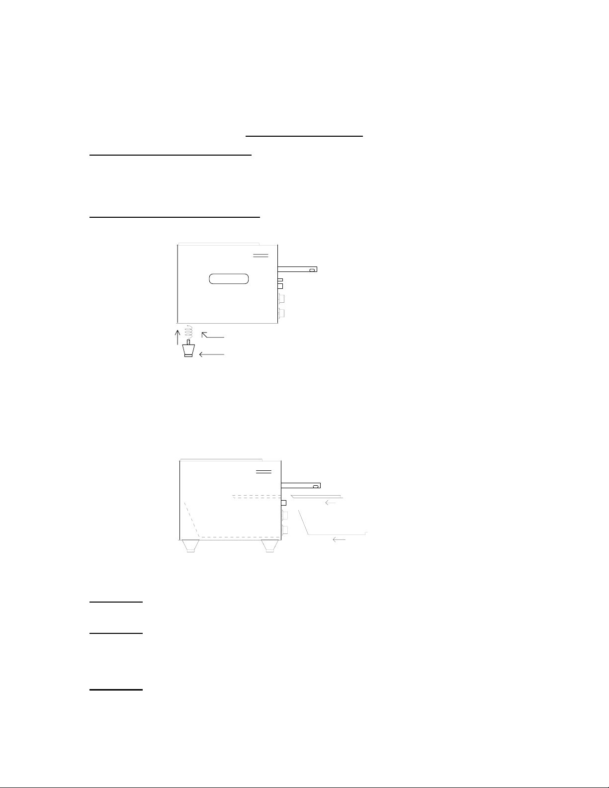
A. Attach legs by screwing into weld nuts, as shown.
HOLMAN
Page 1
ADJUSTABLE LEG: SCREWS INTO WELD NUT LOCATED
AT EACH CORNER ON BOTTOM SIDE OF TOASTER
LEVELING OF THE TOASTER CAN BE DONE BY TURNING
THE FOOT SECTION OF THE LEG COUNTER CLOCKWISE
B. Anti Skid pads are available at no charge and may be adhered to the foot
section of each leg to prevent sliding. Call 1-800-807-9054 for details.
WARNING: Use of these pads are not approved by the National Sanitation
Foundation.
C. Be sure the crumb tray and unload chute are properly installed as shown.
INSERT CRUMB TRAY
AS SHOWN
INNER SKIN/TOAST CHUTE
CAUTION- DO NOT OPERATE UNIT WITHOUT CRUMB TRAY
PROPERLY POSITIONED.
WARNING
INSTALLING/REMOVING ANY PARTS.
WARNING
: MAKE SURE ALL INPUT POWER IS OFF BEFORE
: BEFORE INSTALLING UNIT(S), CHECK WITH LOCAL POWER
COMPANY TO DETERMINE ACTUAL VOLTAGE AT JOB SITE.
NEVER PLUG A 208 VOLT UNIT INTO 240 VOLTS OR A 240
VOLT UNIT INTO 208 VOLTS.
WARNING
: BE ABSOLUTELY SURE THE GROUND CONNECTION FOR THE
RECEPTACLE IS PROPERLY WIRED. NEVER CONNECT UNIT TO
POWER WITHOUT PROPER GROUND CONNECTIONS. IMPROPER
GROUND MAY RESULT IN SEVERE INJURY OR FATALITY.
MJC
REVISED 2/27/95
Page 3

Page 2
OPERATOR'S MANUAL
HOLMAN CONVEYOR TOASTERS
MODELS TH14, TBH14
POWER SAVER SWITCH ( MODEL TH14 ONLY)
Your Holman toaster (Model TH14 only) is equipped with a Power Saver, details
are as follow ;
NEW STYLE
ROTARY POWER SAVER
FULL POWER
OFFOFF
1/4 POWER
STAND BY
OLD STYLE
TOGGLE POWER SAVER
FULL POWER
OFF
STAND BY
FULL POWER- Normal operating position with top and bottom variable
heat controls and variable speed conveyor belt control set at
appropriate settings.
OFF- NEW STYLE: Two off positions are provided so that a single rotation
to either direction will result in the unit being turned OFF.
OFF- OLD STYLE: The center position of the toggle switch turns the unit
completely OFF regardless of heat and speed control settings.
STANDBY- 1/4 power standby. To resume toasting, return to full power and
make a slight reduction in belt speed. This slower belt speed
allows you to start toasting immediately while the unit is returning
to full heat. No need to disturb heat settings.
REVISED 2/28/95 MJC
Page 4
OPERATOR'S MANUAL
HOLMAN CONVEYOR TOASTERS
MODELS TH14, TBH14
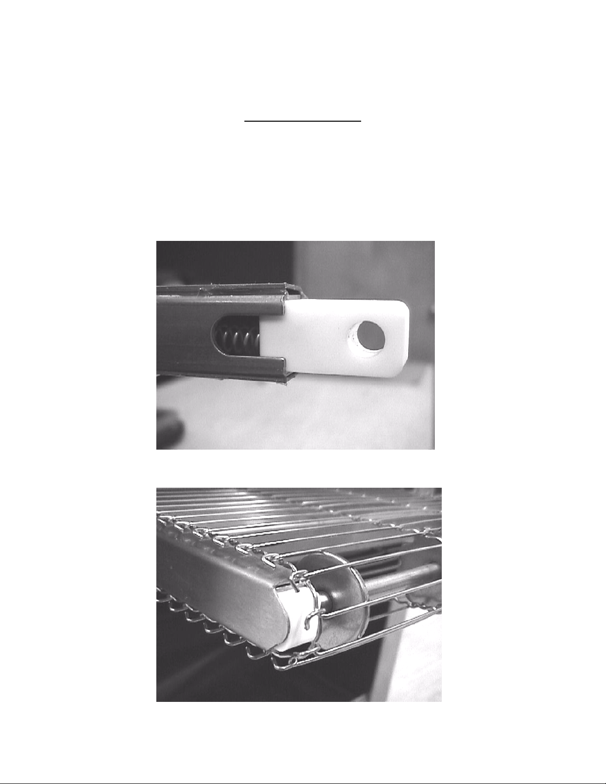
SPRING LOADED FRONT BEARING ASSEMBLY
Your Holman Conveyor Toaster is equipped with a spring-loaded front bearing
assembly as shown below in fig. 1. The spring-loaded bearing assembly keeps
the conveyor belt at a constant tension as the unit heats up and cools down. The
conveyor belt is set to the proper tension when the white teflon bushing is flush
with the end of the extension as shown in fig. 2.
Fig. 1
Page 2a
Fig. 2
REVISED 2/5/00 MJC
Page 5
PAGE 3
OPERATOR'S MANUAL
HOLMAN CONVEYOR TOASTERS
MODELS TH14, TBH14
COOKING PROCEDURES
A. MODEL TH14, BREAD TOASTING
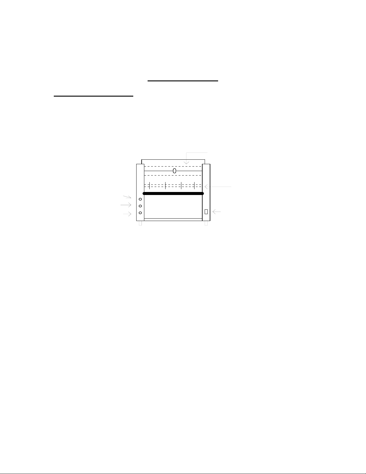
1. Lower the front heat shield all the way down, leaving just enough
clearance for bread slices to pass under the shield into the toasting
cavity.
CONVEYOR
SPEED CONTROL
TOP HEAT
BOTTOM HEAT
ADJUSTABLE HEAT SHUTTER. TO ADJUST
LOOSEN SCREW AT CENTER AND SLIDE UP
OR DOWN.
FRONT IDLER SHAFT
POWER SAVER (TH14) OR
BUN MODE SWITCH (TBH14)
2. Turn top and bottom heat controls to "HI"; turn conveyor speed
control to 50.
3. Allow warm up time of 5 to 10 minutes.
4. Test with a slice of bread.
a. If toast is too light, turn conveyor speed control counterclockwise.
b If toast is too dark, turn conveyor speed control clockwise.
B. MODEL TBH14, BUN TOASTING AND BREAD TOASTING
The model TBH14 is equipped with a Toast/Bun mode switch and has six heater
tubes, four on top and two on bottom.
In the Bun position all four top tubes are energized for bun toasting with no
bottom heat.
CAUTION: In bun mode, both top and bottom variable heat controls must be in
the "HI" position for all four top tubes to heat, the top heat control regulates the
front and rear tubes while the bottom heat control regulates the two center
tubes.
COOKING PROCEDURES CONT. ON PAGE 4
REVISED 2/28/95 MJC
Page 6

PAGE 4
OPERATOR'S MANUAL
HOLMAN CONVEYOR TOASTERS
MODELS TH14, TBH14
MODEL TBH14, BUN TOASTING CONT.
1. On models TBH14, (mode switch in BUN position) lower the front heat
shield as far as possible, leaving just enough clearance for the bun half
to pass under and into the toasting cavity.
BUN MODE
TOP HEAT ONLY
TOAST MODE
TOP & BOTTOM
HEAT
2. Buns will be top toasted only, no bottom heat.
3. Test with a half of a bun.
a. If buns are too light, turn conveyor speed control counterclockwise.
b. If buns are too dark, turn conveyor speed control clockwise.
MODEL TBH14, BREAD TOASTING
In the Toast position two top tubes and two bottom tubes are energized for
bread toasting.
BUN MODE
TOP HEAT ONLY
TOAST MODE
TOP & BOTTOM
HEAT
For proper bread toasting instructions refer to Page 3, Par. A
C. DEEP TOASTING OR BAKING (Units with Variable Heat Controls).
Food products that require deep cooking without exterior burning may be
cooked by reducing the oven temperature (lowering the top and/or bottom
heat controls) and cooking at slower speeds. Some foods may require more
top heat than bottom heat or vice versa. Every product will require some
experimentation to arrive at the correct balance of heat control and conveyor
speed settings.
CAUTION: Each time a setting is changed allow about 5 minutes for the unit
to stabilize.
REVISED 2/28/95 MJC
Page 7

PAGE 5
OPERATOR'S MANUAL
HOLMAN CONVEYOR TOASTERS
MODELS TH14, TBH14
CLEANING PROCEDURES
1. Turn top and bottom heat controls to the OFF position.
2. For lightly soiled conveyor belts, turn conveyor speed control to fastest
setting(100) and wipe with a damp cloth.
3. For heavily soiled conveyors, turn conveyor speed control to fastest setting
(100) and wipe with a light abrasive pad.
4. Turn conveyor speed control off.
5. After the unit cools, remove interior crumb tray and clean. Slide crumb tray
back into position.
DO NOT OPERATE UNIT WITHOUT CRUMB TRAY IN PLACE AS THIS
CAUSES OVERHEATING IN THE CONTROL BOX AND MAY ACTIVATE
THE LIMIT SWITCH.
BOTTOM VIEW OF UNIT
IDLER SHAFT
DRIVE SHAFT
AIR INTAKE
RESET / HIGH LIMIT
(TOP VIEW)
SHOWN WITHOUT TOP COVER
CONVEYOR LINK
CONVEYOR BELT
6. Wipe exterior surface of unit.
LUBRICATION OF DRIVE CHAIN WITH A GRAPHITE BASED LUBRICANT IS REQUIRED AS
PERIODIC MAINTENANCE. CALL HOLMAN FACTORY SERVICE DEPARTMENT FOR
DETAILS.
REVISED 1/28/97 MJC
Page 8

PAGE 6
OPERATOR'S MANUAL
HOLMAN CONVEYOR TOASTERS
TROUBLESHOOTING GUIDE
A. UNIT WILL NOT HEAT, DRIVE MOTOR WILL NOT RUN.
1. Be sure main circuit breaker is switched to the ON position.
2. Check to see if toaster is plugged in and all controls turned on.
B. UNIT WILL NOT HEAT, DRIVE MOTOR RUNS PROPERLY.
1. Check to see if both top and bottom heat control have been turned to HI.
MODELS TH14, TBH14
2. Press heat limit reset button on the bottom of the control box as shown
below. If this reactivates the heater tubes, see HEAT LIMIT SWITCH in
section C.
C. HEAT LIMIT SWITCH
Your Holman conveyor toaster is equipped with an automatically activated
temperature (heat) limit switch which interrupts the heater tube connections
if the air temperature in the control box exceeds 190F (88C). This heat limit
switch can be reset manually by pushing the red button at the bottom of
the control box.
BOTTOM VIEW OF UNIT
AIR INTAKE
RESET / HIGH LIMIT SWITCH
THE HEAT LIMIT SWITCH IS ACTIVATED WHEN THERE IS NOT
SUFFICIENT AIR FLOW GENERATED BY THE COOLING FAN. IF THIS
SHOULD OCCUR:
1. DISCONNECT UNIT FROM POWER SOURCE.
2. Check to see if air intake vent in the bottom center of the control box
is free of dust, grease or other obstructions.
3. Check if crumb tray is in place. NEVER OPERATE UNIT WITHOUT
CRUMB TRAY IN PLACE AS THIS CAUSES OVERHEATING IN THE
CONTROL BOX.
4. If no obstructions to the air flow can be found and if the crumb tray is in
place, call Holman Factory Service Department at 1-800-807-9054 for
assistance.
TROUBLESHOOTING GUIDE CONT. ON PAGE 7
Page 9

PAGE 7
OPERATOR'S MANUAL
HOLMAN CONVEYOR TOASTERS
MODELS TH14, TBH14
TROUBLESHOOTING GUIDE CONT.
D. CONVEYOR WILL NOT TURN, UNIT HEATS PROPERLY.
1. DISCONNECT UNIT FROM POWER SOURCE.
2. Remove right hand side panel (from operator's position). Remove drive
chain from sprocket and motor shaft as shown. Manually move conveyor
belt to check for mechanical binding. If conveyor moves freely, call
Holman Factory Service Department at 1-800-807-9054 as drive motor
and/or speed control may need replacement.
DRIVE
MOTOR
FAN
MOTOR
RESET
HIGH LIMIT
TROUBLESHOOTING GUIDE CONT. ON PAGE 8
BACK SIDE OF UNIT
SHOWING CONTROL BOX
REAR BEARING
DRIVEN SPROCKET
DRIVE CHAIN
DRIVE SPROCKET
REVISED 1/28/97 MJC
Page 10

R
O
T
P
PAGE 8
OPERATOR'S MANUAL
HOLMAN CONVEYOR TOASTERS
TROUBLESHOOTING GUIDE CONT.
MODELS TH14, TBH14
E. CONVEYOR TURNS AT ONE SPEED REGARDLESS OF SPEED
CONTROL SETTING.
1. Call Holman Factory Service Department at 1-800-807-9054 as speed
control should be replaced.
MAINTENANCE PROCEDURES
A. REPLACING HEATER TUBES (as below)
1. DISCONNECT UNIT FROM POWER SOURCE.
2. Remove right and left side panels.
3. Remove heater tube wire from terminal block connection, keeping
top and bottom wires separate.
4. Remove heater tube retainers by removing retaining screws with washer.
5. Gently,
6. Gently,
pull defective heater tube out of unit.
put new heater tube into unit.
7. Replace heater tube retainers, reconnect heater tube wires to terminal
block and install side panels.
5
TERMINAL BLOCK
HEATER TUBES
HEATER TUBE RETAINER
SCREW
WASHER
CONVEYOR
SPEED CONTROL
TOP HEAT
BOTTOM HEAT
TROUBLESHOOTING GUIDE CONT. PAGE 9
HEATER TUBE RETAINE
1. SPEED CONTROL
2. INFINITE SWITCH
3. SPEED CONTROL KN
4. INFINITE SWITCH KNO
5. REAR BEARING
1
2
2
ADJUSTABLE HEAT SHUTTER. TO ADJUS
LOSEN SCREW AT CENTER AND SLIDE U
OR DOWN.
3
4
4
FRONT IDLER SHAFT
POWER SAVER (TH14) OR
BUN MODE SWITCH (TBH14)
REVISED 1/28/97 MJC
Page 11

PAGE 9
OPERATOR'S MANUAL
HOLMAN CONVEYOR TOASTERS
MODELS TH14, TBH14
MAINTENANCE PROCEDURES CONT.
B. REPLACING FAN MOTOR
1. DISCONNECT UNIT FROM POWER SOURCE.
2. Remove control box cover at lower rear of unit.
3. Unplug power supply cord from fan motor.
4. From the underside of unit, remove (4) screws which hold fan motor in
place.
5. Put replacement motor in place and secure to the unit with screws.
6. Reconnect power supply cord to fan motor.
7. Replace control box cover.
FAN CORD
FAN MOTOR
FAN MOTOR MOUNTING SCREWS
TROUBLESHOOTING GUIDE CONT. PAGE 10
BACK SIDE OF UNIT
SHOWING CONTROL BOX
FAN MOTOR
REVISED 2/28/95 MJC
Page 12

PAGE 10
OPERATOR'S MANUAL
HOLMAN CONVEYOR TOASTERS
MODELS TH14, TBH14
MAINTENANCE PROCEDURES CONT.
C. REPLACING BELT DRIVE MOTOR
1. DISCONNECT UNIT FROM POWER SOURCE.
2. Remove right side panel and lower control box cover.
3. Remove sprocket from motor shaft.
4. Remove the wire from terminal block connecting the drive motor to
internal wiring. On units rated 208 or 240 volts, note which color leads
are being used for these connections and which lead is capped with
white tape. The new motor should use the same arrangement.
5. Remove screws holding motor in place.
6. Put new motor in place and attach loosely with mounting screws.
7. Replace sprocket on motor shaft.
8. Slide motor until the drive chain has about 1/8" slack when lightly pushed
9. Tighten screws to secure motor.
10. Rewire leads same as removed in step 4.
11. Replace side panel and control box cover.
9. at the center of its top open run.
WASHERS
SPROCKET
DRIVE MOTOR
FAN MOTOR
FAN CORDSCREWS
RESET
BACK SIDE OF UNIT
SHOWING CONTROL BOX
IF ASSISTANCE IS REQUIRED FOR THIS OR ANY OTHER PROCEDURE IN
THIS MANUAL CALL HOLMAN FACTORY SERVICE DEPARTMENT AT
1-800-807-9054 24 HOURS/DAY 7 DAYS/WEEK.
REVISED 2/28/95 MJC
Page 13

PARTS LIST
2E-200574 1 Ceramic Fan Switch
06/23/06 RB
PAGE 11
OPERATOR'S MANUAL
HOLMAN CONVEYOR TOASTERS
MODELS TH14, TBH14
3.
1.
2.
28.
5a.
27.
16.
17.
26.
14.
19.
22.
21.
14.
18.
20.
23/23a.
24.
25.
13.
15.
4.
10.
11.
9.
8.
7.
12.
5.
6.
PART # QTY. DESCRIPTION PART # QTY. DESCRIPTION
1). 400847 1 Top Cover 14). 200700 1 Idler Bushing
*2). 197863 4 Heater T ube, 240 Volt 15). 200652 1 Fan Grill
*2a). 197852 4 Heater Tube, 220 Volt 16). 100905 1 Idler Shaft
*2b). 197851 4 Heater Tube, 208 Volt 17). 100508 1 Crumb Tray
3). 400967 2 Retainer, Heater Tube 18). 200538 2 Infinite Switch
4). 160004 1 Conveyor Belt 19). 118042 1 Speed Control
5). 400931 1 Back Panel, Lower 20). 200566 1 Reset Switch
5a). 400930 1 Back Panel, Upper 21). 200702 1 Knob, Infinite Switch
6). 401382 1 Side Panel, Left 22). 200703 2 Knob, Speed Control
6a). 400979 1 Side Panel, Right 23). 200547 1 Power Saver Switch
7). 150013 1 Drive Chain 23a) 200546 1 Bun Mode Switch (TBH14)
8). 200645 1 Drive Sprocket 24). 200709 4 Leg, 1" Plastic
9). 200645 1 Driven Sprocket 25). 140030 1 Cord/Plug Set
10). 100902 1 Drive Shaft 26). 400919 1 Toast Chute
11). 112261 1 Bearings 27). 401089 1 Nose Gaurd
12). 200509 1 Drive Motor, 60Hz 28). 400899 1 Heat Shutter
12a). 200590 1 Drive Motor, 50Hz 29). 200736 2 Spring, (not shown)
13). 200560 1 Fan Motor
*NOTE:
6 ea. Heater Tubes In Models TBH14 and TH14NY. REV. 12/20/05 RMS
Page 14

*NOTE: 6 ea. Heater Tubes In Models TBH14 and TH14NY. REV. 2/4/00 MJC
PAGE 12
OPERATOR'S MANUAL
HOLMAN CONVEYOR TOASTERS
MODELS TH14, TBH14
WIRE DIAGRAM : TBH14
Top Heat
Bottom Heat
Bun Mode
Switch
Cooling
Fan
High Limit
Reset
black :common
Conveyor
Motor
blue :220/240 vac
white :208 vac
Plug Configuration
H2
P
L2
H2
P
L2
Speed
Control
H1
L1
H1
L1
Top
Heat Control
Bottom
Heat Control
NEMA 6-30 P
REV.3/5/99 MJC
Page 15

PAGE 13
OPERATOR'S MANUAL
HOLMAN CONVEYOR TOASTERS
MODELS TH14, TBH14
WIRE DIAGRAM
MODEL TH14
TOP HEAT
BOTTOM HEAT
POWER SAVER
PLUG CONFIGURATION
6-30P, 30 AMP
CONVEYOR
MOTOR
WHITE 208 VAC
RESET
SWITCH
BLUE 220/240 VAC
BLACK COMMON
SPEED CONTROL
FAN MOTOR
L1
L2
GROUND
REV. 4/2/99 MJC
 Loading...