

Page 1
IL1367
ADD-A-SECTION
for 36” RANGE
R12-ATG
R12-ATH
Commerical & Marine
Installation and
Operation
Instructions
2M-W821 Rev. B 2/6/12
R12-ATH
R12-ATG
1
Page 2
These symbols are intended to alert the user to the presence of
important operating and maintenance instructions in the manual
accompanying the appliance.
FOR YOUR SAFTEY
DO NOT STORE OR USE GASOLINE OR OTHER FLAMMABLE VAPORS AND LIQUIDS IN
THE VICINTIY OF THIS OR ANY OTHER APPLIANCE.
POST IN PROMINENT LOCATION
INSTRUCTIONS TO BE FOLLOWED IN THE EVENT USER SMELLS GAS. THIS
INFORMATION SHALL BE OBTAINED BY CONSULTING YOUR LOCAL GAS SUPPLIER.
AS A MINIMUM, TURN OFF THE GAS AND CALL YOUR GAS COMPANY AND YOUR
AUTHORIZED SERVICE AGENT. EVACUATE ALL PERSONNEL FROM THE AREA.
WARNING
IMPROPER INSTALLATION, ADJUSTMENT, ALTERATION, SERVICE OR MAINTENANCE
CAN CAUSE PROPERTY DAMAGE, INJURY OR DEATH. READ THE INSTALLATION,
OPERATION & MAINTENANCE INSTRUCTIONS THOROUGHLY BEFORE INSTALLING OR
SERVICING THIS EQUIPMENT.
WARNING
RISK OF FIRE OR ELECTRIC SHOCK
DO NOT OPEN
WARNING, TO REDUCE THE RISK OF ELECTRICAL SHOCK, DO NOT REMOVE
CONTROL PANEL. NO USER-SERVICABLE PARTS INSIDE.
REPAIRS SHOULD BE DONE BY AUTHORIZED SERVICE PERSONNEL ONLY.
NOTICE
Using any part other than genuine Lang factory supplied parts relieves the manufacturer of all
liability.
Lang reserves the right to change specications and product design without notice. Such
revisions do not entitle the buyer to corresponding changes, improvements, additions or
replacements for previously purchased equipment.
Due to periodic changes in designs, methods, procedures, policies and regulations,
the specications contained in this sheet are subject to change without notice. While
Lang exercises good faith efforts to provide information that is accurate, we are not
responsible for errors or omissions in information provided or conclusions reached as a
result of using the specications. By using the information provided, the user assumes all risks
in connection with such use.
MAINTENANCE AND REPAIRS
Contact your local dealer for service or required maintenance. Please record the model number, serial
number, voltage and purchase & Installation Information in the area below and have it ready when you
call to ensure a faster service.
SAFETY SYMBOL
Model No.:
Serial No.:
Voltage:
1-Phase
or 3 Phase:
Purchased From:
Location:
Purchase
Date:
Installed Date:
2
Page 3

PROBLEMS, QUESTIONS or CONCERNS
Before you proceed consult you authorized Lang service agent directory
or
Call the Lang Technical Service & Parts Department at 314-678-6315.
TABLE OF CONTENTS
Table Of Contents . . . . . . . . . . . . . . . . . . . . . . . . . . . 3
Specications
Equipment Description . . . . . . . . . . . . . . . . . . . . . . . . 5
Recieving the Unit . . . . . . . . . . . . . . . . . . . . . . . . . . . 5
Installation
Initial Start-up . . . . . . . . . . . . . . . . . . . . . . . . . . . . . 7
Operation
Cleaning & Maintenance Procedures . . . . . . . . . . . . . . . . . 8
Calibration
Troubleshooting
Parts Lists . . . . . . . . . . . . . . . . . . . . . . . . . . . . . . . 13
Wiring Diagrams . . . . . . . . . . . . . . . . . . . . . . . . . . . . 14
. . . . . . . . . . . . . . . . . . . . . . . . . . . . . 4
. . . . . . . . . . . . . . . . . . . . . . . . . . . . . . . 6
. . . . . . . . . . . . . . . . . . . . . . . . . . . . . . . 7
. . . . . . . . . . . . . . . . . . . . . . . . . . . . . . . 8
. . . . . . . . . . . . . . . . . . . . . . . . . . . . 9
NOTICE Service on this or any other Lang appliance must be performed by
qualied personnel only. Consult your Lang Authorized Service Agent
Directory.
You can call our toll free number 314-678-6315 or visit our website
www.langworld.com for the service agent nearest you.
3
Page 4
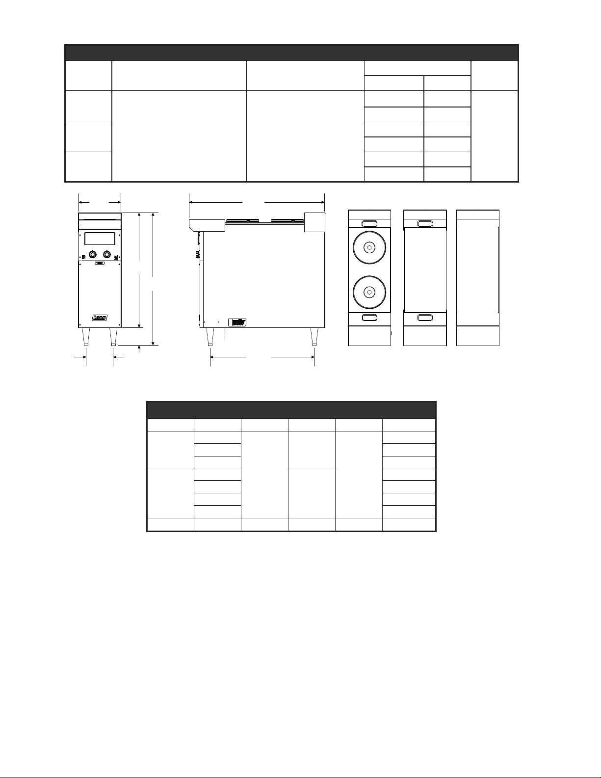
Model Height x Width x Depth
32.2”
818mm
12”
305mm
5”
127mm
37.1”
944mm
38.1”
968mm
29.3”
744mm
6.3”
160mm
Electrical
Connection
Front View Side View R12-ATH
Top View
R12-ATG
Top View
12” X 24”
Hot Top
R12-ATI
Top View
IL2266
12” Unheated
Work Surface
French Plate
R12-ATG
R12-ATH
37.1" x 12.0" x 38.1" 944mm x
305mm x 968mm
R12-ATI
Specications
Clearance from
combustible surface
Sides & Back 4" (100mm)
Weight
Actual Shipping
130 lbs. 160lbs.
59 kg 73 kg
90 lbs 120 lbs
41 kg 55 kg
90 lbs 120 lbs
41 kg 55 kg
Freight
Class
85
Electrical Specications
Model Voltage Hz kW Phase Amps/Line
208V
R12-ATG
240V 20.8
5.0
480V 10.4
R12-ATH
208V
240V 21.7
440V 10.0
60
1
5.2
480V 10.8
R12-ATI - - - - -
24.0
25.0
4
Page 5
Equipment Description
R12-ATH
Top View
R12-ATG
Top View
12” X 24”
Hot Top
R12-ATI
Top View
IL2267
12” Unheated
Work Surface
French Plate
R12-ATG & R12-ATH
Exterior
The unit dimensions are 30” (76.2cm) high, 38” (96.5cm) deep, and 12” (30.5cm) wide.
The sides, bottom, and rear wall are constructed of stainless steel.
The Add-A-Section surface is available in two different congurations.
Controls
The Add-A-Section is available with various controls depending
upon model number. Below are the layout of the top conguration
with its proper model number and a brief description of the
controls.
R12-ATH
Two solid French Plates controlled by two six-heat switches with a
temperature range of 0-750°F
R12-ATG
One 12” x 24” Hotplate controlled by a thermostat with a range of
0-850°F
R12-ATI
One 12” wide unheated work surface. This conguration has no
electrical connections.
CAUTION
Receiving The Unit
Upon receipt, check for freight damage, both visible and concealed. Visible
damage should be noted on the freight bill at the time of delivery and signed
by the carrier’s agent. Concealed loss or damage means loss or damage,
which does not become apparent until the merchandise has been unpacked.
If concealed loss or damage is discovered upon unpacking, make a written
request for inspection by the carrier’s agent within 15 days of delivery. All
packing material should be kept for inspection. Do not return damaged
merchandise to Lang Manufacturing. File your claim with the carrier.
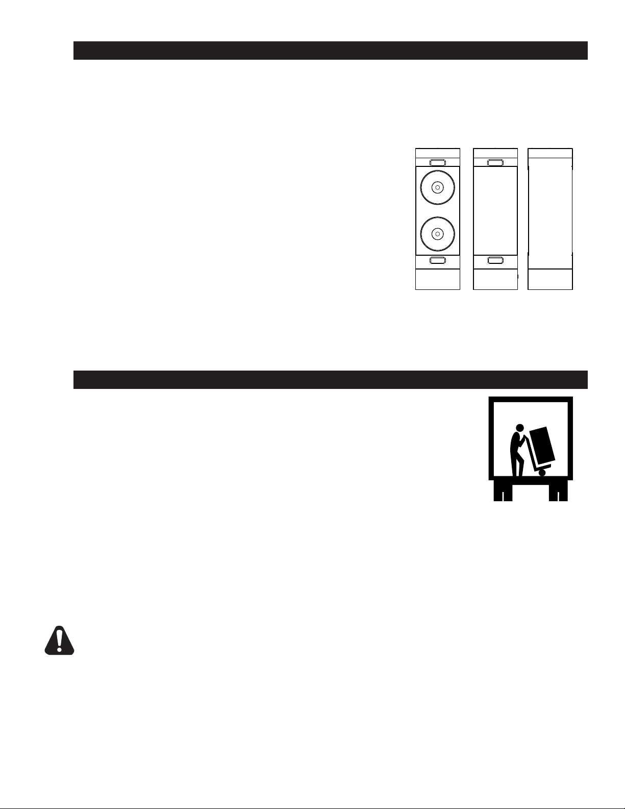
Location
Prior to un-crating, move the unit as near its intended location as practical. The crating will help
protect the unit from the physical damage normally associated with moving it through hallways and
doorways.
Un-crating
The unit will arrive completely assembled inside a wood frame covered by cardboard box and strapped
to a skid. Remove the cardboard cover, cut the straps and remove the wood frame.
Remove unit from skid and place in intended location.
UNIT WEIGHS 160 LBS (72.5 kilograms). FOR SAFE HANDLING, INSTALLER SHOULD
OBTAIN HELP AS NEEDED, OR EMPLOY APPROPRIATE MATERIALS HANDLING
EQUIPMENT (SUCH AS A FORKLIFT, DOLLY, OR PALLET JACK) TO REMOVE THE
UNIT FROM THE SKID AND MOVE IT TO THE PLACE OF INSTALLATION.
ANY STAND, COUNTER OR OTHER DEVICE ON WHICH THE UNIT WILL BE LOCATED
MUST BE DESIGNED TO SUPPORT THE WEIGHT OF THE UNIT (160 LBS.).
SHIPPING STRAPS ARE UNDER TENSION AND CAN SNAP BACK WHEN CUT.
5
Page 6

WARNING
Installation
Installing the Legs
To install the 6-inch legs, remove the legs from the packing, place some cardboard on the oor
and gently tip the unit onto its back or side. Fasten the legs into the threaded holes provided
and then gently ip the oven onto its legs.
Electrical Connection
The electrical connection must be made in accordance with local codes or in the absence of
local codes with NFPA No. 70 latest edition (in Canada use: CSA STD. C22.1). The electrical
connection can be made at the 1 1/4” knockout located in the bottom panel of the unit 8 inches
from the front.
The unit can now be connected to power.
THIS APPLIANCE MUST BE GROUNDED AT THE TERMINAL PROVIDED.
FAILURE TO GROUND THE APPLIANCE COULD RESULT IN ELECTROCUTION
AND DEATH.
INSTALLATION OF THE UNIT MUST BE DONE BY PERSONNEL QUALIFIED
TO WORK WITH ELECTRICITY. IMPROPER INSTALLATION CAN CAUSE
INJURY TO PERSONNEL AND/OR DAMAGE TO EQUIPMENT. UNIT MUST BE
INSTALLED IN ACCORDANCE WITH ALL APPLICABLE CODES.
WARNING
CAUTION
NOTICE The data plate is located behind removable front panel. The
unit voltage, wattage, serial number, wire size, and clearance
specications are on the data plate. This information should
be carefully read and understood before proceeding with the
installation.
The installation of any components such as a vent hood, grease
extractors, re extinguisher systems, must conform to their
applicable National, State and locally recognized installation
standards.
MAKE SURE THE MAIN POWER SUPPLY TO THE UNIT IS TURNED OFF AT
THE SOURCE PRIOR TO CONNECTING POWER TO THE RANGE.
BE SURE THE POWER SUPPLY VOLTAGE MATCHES THE VOLTAGE SPECIFIED
ON THE NAMEPLATE LOCATED ON THE FRONT OF THE RANGE.
Phasing
The Add-A-Section is a single-phase unit.
6
Page 7

Initial Start-Up
Prior to putting any unit into full time operation at normal cooking temperatures, it must be
thoroughly “seasoned” or dried out. Moisture absorption in the closed spaces, in the insulation and
even inside the heating elements can cause future trouble if not properly treated.
R12-ATG
To “dry out” the Hot Plate, set the thermostat dial at 250°F and turn on the power switch. Allow unit
to cycle at least 15 minutes at this heat level. Reset the thermostat to 350°F allowing the same
time. Then reset the thermostat to 450°F allowing the same time. Continue doing this until you
reach 850°F then allow the unit to maintain this temperature for a minimum of 4 hours. More time
may be required if the unit has to operate in a moist environment.
If the unit is out of use for three or more days, a one-hour preheat schedule should be used,
especially when exposed to high humidity and/or cool temperatures.
R12-ATH
To “dry out” the French Plate, set the six-heat switch to the rst setting and turn on the power
switch. Allow unit to cycle at least 15 minutes at this heat level. Reset the six-heat switch to
position two and allow the same time. Reset the six-heat switch to position three and allow the
same time. Continue doing this until you reach position six (6) then allow the unit to maintain the
temperature for a minimum of four (4) hours. More time may be required if the unit has to operate
in a moist environment.
If the unit is out of use for three or more days, a one-hour preheat schedule should be used,
especially when exposed to high humidity and/or cool temperatures.
NOTICE During the rst few hours of operation, you may notice a small amount
CAUTION
of smoke coming from the unit, and a faint odor from the smoke. This is
normal for a new unit and will disappear after the rst few hours of use.
Operation
ALWAYS KEEP THE AREA NEAR THE APPLIANCE FREE FROM COMBUSTIBLE
MATERIALS.
KEEP FLOOR IN FRONT OF EQUIPMENT CLEAN AND DRY. IF SPILLS OCCUR,
CLEAN IMMEDIATELY, TO AVOID THE DANGER OF SLIPS OR FALLS.
12” x 24” hot plate controlled by high temperature thermostats. Temperature ranges from 0-850°F.
Recommended: Stockpots and heavy kettle work.
Round French Plates, controlled by indicating type 6-heat switch. Temperature ranges from 0750° F. Recommended: Light duty saucepans and small stockpots. Not Recommended: heavy
stockpots, heavy urns, or kettles.
7
Page 8

WARNING
CAUTION
Cleaning & Maintenance Procedures
KEEP WATER AND SOLUTIONS OUT OF CONTROLS. NEVER SPRAY OR HOSE
CONTROL CONSOLE, ELECTRICAL CONNECTIONS, ETC.
MOST CLEANERS ARE HARMFUL TO THE SKIN, EYES, MUCOUS MEMBRANES
AND CLOTHING. PRECAUTIONS SHOULD BE TAKEN TO WEAR RUBBER GLOVES,
GOGGLES OR FACE SHIELD AND PROTECTIVE CLOTHING. CAREFULLY READ
THE WARNING AND FOLLOW THE DIRECTIONS ON THE LABEL OF THE CLEANER
TO BE USED.
The unit should be thoroughly cleaned at least once a week in addition to the normal daily cleaning
to insure against the accumulation of foreign material.
NOTICE: Any cleaner used should be marked “SAFE ON ALUMINUM”.
Keep-drip pans under Add-A-Section Top plates clean.
Keep hotplate surfaces clean.
Outside of unit and top should be kept clean.
Electric equipment is inherently clean and sanitary, but may become unsanitary if dirt is allowed to
accumulate on it. Take advantage of the clean, sanitary features of electric equipment, give it the
regular attention that it deserves the same as any other highly perfected machinery, to insure best
results and continued high operating efciency.
Calibration
Calibration Check
Place thermometer or thermocouple in the center of Hotplate.
Set thermostat to 350°F.
Allow the Hotplate to Preheat for at least half an hour.
Note cycle on temperatures and cycle off temperatures for 3 cycles. (Red indicator light indicates
when oven is calling for heat)
After 3 cycles average the temperature. ( Add all six temperatures and divide by 6)
Calibration Adjustment
A 1/16” at blade screwdriver with a 2” shaft is required to make adjustments on the thermostat.
Maintain the oven temperature at 350°F.
Without turning the thermostat, remove the knob.
Locate the adjustment screw at the base of the shaft and insert the screwdriver.
Grasp the shaft and turn the screwdriver. Counter clockwise to increase and clockwise to
decrease (1/8 of a turn will move the temperature 5-7° in either direction).
Reinstall the oven knob and recheck the oven temperature.
8
Page 9

Symptoms
Tests
NOTICE: Service on this, or any other, LANG appliance must be performed by
WARNING
CAUTION
Troubleshooting
What follows is a chart of Symptoms, Possible Causes, and Remedy’s to aid in diagnosing faults
with the oven.
Refer to the Symptoms column to locate the type of failure then to the Possible Cause for the items
to be checked and the Remedy to column for possible solutions.
qualied personnel only. Consult your authorized service station
directory or call the factory at 314-678-6315,
or WWW.LANGWORLD.COM For the service station nearest you.
BOTH HIGH AND LOW VOLTAGES ARE PRESENT INSIDE THIS APPLIANCE WHEN
THE UNIT IS PLUGGED/WIRED INTO A LIVE RECEPTACLE. BEFORE REPLACING
ANY PARTS, DISCONNECT THE UNIT FROM THE ELECTRIC POWER SUPPLY.
If an item on the list is followed by an asterisk (*), the work should be done by a factory authorized
service representative.
USE OF ANY REPLACEMENT PARTS OTHER THAN THOSE SUPPLIED BY
LANG OR THEIR AUTHORIZED DISTRIBUTORS CAN CAUSE BODILY INJURY
TO THE OPERATOR AND DAMAGE TO THE EQUIPMENT AND WILL VOID ALL
WARRANTIES.
Troubleshooting
Symptom Possible Cause
No power to Unit
Hotplate will not heat
French plate will not heat
Possible Cause Test
Product is cooked too long No test available, operational condition
Failed Six-heat switch Call factory or reference service manual
Failed thermostat Verify calibration
Failed element Remove the wires and check for continuity across the element
Defective Thermostat
Defective oven element
No power to Range
Failed 6-heat switch
Failed element
9
Page 10

SK2518 Rev. - 6/2/2011
Model: R12-ATG, ADD A SECTION
2
23
18
17
13
14
15
16
10
10
11
7
12
10
9
8
22
21
20
19
3
4
5
1
6
24
10
Page 11

PARTS LIST June 3, 2011
Model: R12-ATG ADD A SECTION
Fig No Part No Qty Description Application
1 P9-50302-303 1 SEARAIL ASSY 1' MARINE
2 P9-50302-305 1 SEARAIL LH SDE ADD,RF&500 MARINE
3 P9-50302-318 5 SEARAIL SIDE TO SIDE ADD MARINE
4 P9-50302-306 1 SEARAIL RH SDE ADD,RF&500 MARINE
5 2C-20109-04 8 SCRW THD MS SS 10-32X3/8 MARINE
2N-11010-34
6
7
8 2E-31200-02 1 LUG GROUNDING UL APPROVED ALL
9 2C-20202-10 1 WSHR PLT #10 LOCK EXT ALL
10 2C-20103-02
11 P9-ADD-105 1 BOTTOM FRONT PANEL ALL
12 K9-60301-43-1 1 DIE CAST LOG + TINNERMAN ALL
13 2R-70702-20 1 DIAL PLT 850o ALL
14 2R-70700-01 1 KNOB BLNK UNIVERSAL BLACK ALL
15 2R-70703-03 1 CLIP KNOB HAT SHAPED ALL
16 2C-20101-64 2 SCRW PHD MS M4 X 6 PLTD ALL
17
18 P9-ADD-110 1 TOP FRONT PANEL 32S-12 ALL
19 2T-30402-23 1 STAT ADJ 850o 48C/T NAK ALL
20 2K-70801-04 1 SNAP BUSH 3/4 SB750-10 ALL
21 2C-20111-01 4 SCRW HXHD CAP 1/4-20X1/2 MARINE
22 2C-20204-02 4 WASHER SS 1/4 SPLIT LOCK MARINE
23 P9-50300-49-2 1 GRAB BAR ASSY 12
24
2N-11010-35 HOTPLATE 240V 5000W CAST 240V
2N-11010-36 HOTPLATE 480V 5000W CAST 480V
2A-72500-06
2A-72500-03 LEG 5 SS ADJ WITH 3/4-10 NON-MARINE
Y9-31601-01-1
Y9-31601-02-1 PILOT LT 480V W/TIN CLIP R12-ATG-480V
P9-ADD-219
P9-ADD-219-1 PAN ASSEMBLY MARINE MARINE
HOTPLATE 208V 5000W CAST 208V
1
LEG 5 1/2W/BOLT DOWN ADJ MARINE
4
17
SCRW SM PLT 10 X .5 PHLSL
11 R12-ATG-480V
PILOT LT 250V W/TIN CLIP R12-ATG-208V, 208VM, 240V
1
PAN ASSEMBLY ALL
1
R12-ATG-208V, 208VM, 240V
MARINE
11
Page 12

SK2519 Rev. - 6/2/2011
Model: R12-ATH, ADD A SECTION
2
6
7
23
18
14
15
16
17
11
11
12
8
13
11
10
9
22
21
20
19
3
4
5
1
24
12
Page 13

PARTS LIST February 6, 2012
Model: R12-ATH ADD A SECTION
Fig No Part No Qty Description Application
1 P9-50302-303 1 SEARAIL ASSY 1' MARINE
2 P9-50302-305 1 SEARAIL LH SDE ADD,RF&500 MARINE
3 P9-50302-318 5 SEARAIL SIDE TO SIDE ADD MARINE
4 P9-50302-306 1 SEARAIL RH SDE ADD,RF&500 MARINE
5 2C-20109-04 8 SCRW THD MS SS 10-32X3/8 MARINE
2N-11120-12
6
7 P9-50300-82-1 1 EGO PLATE FRM ASSY PHANT ALL
8 2A-72500-06 4 LEG 5 1/2W/BOLT DOWN ADJ MARINE
9 Y9-31200-02-1 1 GROUNDING LUG/+LABEL ALL
10 2C-20202-10 1 WSHR PLT #10 LOCK EXT ALL
11 2C-20103-02 9 SCRW SM PLT 10 X .5 PHLSL ALL
12 P9-ADD-105 1 BOTTOM FRONT PANEL ALL
13 2M-60301-43 1 DIE CAST PLT LANG SATIN ALL
14 2R-70702-34 2 DIAL PLT 6-HEAT SWITCH ALL
15 2R-70700-01 2 KNOB BLNK UNIVERSAL BLACK ALL
16 2R-70703-03 2 CLIP KNOB HAT SHAPED ALL
17 2C-20101-64 4 SCRW PHD MS M4 X 6 PLTD ALL
18 P9-ADD-110-3 1 TOP FRONT PANEL ALL
19 2E-30304-09 2 SWTROT 6 HEAT+OFF208/240V ALL
20 2K-70801-04 1 SNAP BUSH 3/4 SB750-10 ALL
21 2C-20111-01 4 SCRW HXHD CAP 1/4-20X1/2 MARINE
22 2C-20204-02 4 WASHER SS 1/4 SPLIT LOCK MARINE
23 P9-50300-49-2 1 GRAB BAR ASSY 12 MARINE
24
2N-11120-13 ELMNT TK 240V 2600W 240V
2N-11120-14 ELMNT TK 480V 2600W 440V, 480V
P9-ADD-219
P9-ADD-219-1 PAN ASSEMBLY MARINE
ELMNT TK 208V 2600W 208V
2
PAN ASSEMBLY ALL
1
MARINE
13
Page 14

1
1 THERMOSTAT
INDICATOR LIGHT
EGO HOT PLATE
2
3
L1 L2
2
3
1667
1667 1667
Wiring Diagram
Model: R12-ATG
Wiring Diagram
Model: R12-ATH
SK2519, Rev. -
1 2 3 4
1
P1 P2
2 3 4
1 2 3 4
1
P1 P2
2 3 4
2
1
1 SIX-HEAT SWITCH
FRENCH PLATE
1
14
Page 15

15
Page 16

STAR INTERNATIONAL HOLDINGS INC. COMPANY
Star - Holman - Lang - Wells - Bloomeld - Toastmaster
10 Sunnen Drive, St. Louis, MO 63143 U.S.A.
16
 Loading...