

Page 1

®
CONVEYOR
SANDWICH TOASTER
MODEL
QT14B, QT14BR,
QT14BW, QT14BWR
Installation and
Operation
Instructions
2M-Z9702 Rev. I 4/14/09
QT14BR
1
Page 2

2
These symbols are intended to alert the user to the presence of
important operating and maintenance instructions in the manual
accompanying the appliance.
RETAIN THIS MANUAL FOR FUTURE REFERENCE
NOTICE
Using any part other than genuine Star factory supplied parts relieves the
manufacturer of all liability.
Star reserves the right to change specifi cations and product design without
notice. Such revisions do not entitle the buyer to corresponding changes,
improvements, additions or replacements for previously purchased
equipment.
Due to periodic changes in designs, methods, procedures, policies and
regulations, the specifi cations contained in this sheet are subject to change
without notice. While Star Manufacturing exercises good faith efforts to provide
information that is accurate, we are not responsible for errors or omissions
in information provided or conclusions reached as a result of using the
specifi cations. By using the information provided, the user assumes all risks in
connection with such use.
MAINTENANCE AND REPAIRS
Contact your local authorized service agent for service or required maintenance. Please record the model
number, serial number, voltage and purchase date in the area below and have it ready when you call to
ensure faster service.
SAFETY SYMBOL
Model No.
Serial No.
Voltage
Purchase Date
Business 8:00 am to 4:30 p.m. Central Standard Time
Hours:
Telephone: (800) 807-9054 Local (314) 781-2777
Fax: (800) 396-2677 Local (314) 781-2714
E-mail Parts@star-mfg.com
Service@star-mfg.com
Warranty@star-mfg.com
Website: www.star-mfg.com
The Star Service Help Desk
Authorized Service Agent
Reference the listing provided with the unit
or
for an updated listing go to:
Website: www.star-mfg.com
E-mail Service@star-mfg.com
Telephone: (800) 807-9054 Local (314) 781-2777
Mailing Address: Star Manufacturing International Inc.
10 Sunnen Drive
St. Louis, MO 63143
U.S.A
2
Page 3

TABLE OF CONTENTS
PAGE
Star Contact Information 2
Specications 3
General Information Data 4
Inspection & Assembly 4
Assembly and Installation 4-5
Electrical Connection 5
Oven Components 5
Stacking Ovens 6
Daily Operation 6
Cleaning
Daily 7
Weekly 8
Monthly 9
Maintenance and Repairs 10-11
Troubleshooting Guide 12
Limited Equipment Warranty 13
Wiring Diagrams 14-16
Exploded View Illustration & Parts List 18-21
SPECIFICATIONS
QT14B,
Rating/Connection: 7,800 Watts
NEMA Plug: N/A
Electrical Supply: Separate service per toaster - 37.5 Amp, 208 VAC, 1 phase, 60 Hz
Separate service per toaster - 32.5 Amp, 240 VAC, 1 phase, 60/50 Hz
Separate service per toaster - 21.7 Amp, 208 VAC, 3 phase, 60 Hz
Approximate Weight (QT14B Oven with Legs): Installed - 170 Lbs (77.1 kg)
Dimensions: Width: 55" (139.7 cm) - Oven with Trays
Depth: 24" (60.9 cm)
Height: 20" (50.8 cm) - Single Oven with Legs
QT14BR, QT14BW, QT14BWR
QT14B, QT14BR, QT14BW, QT14BWR
Rating/Connection: 7,950 Watts
NEMA Plug: N/A 3 Phase: N/A
Electrical Supply: Separate service per toaster - 36.1 Amp, 220 VAC, 1 phase, 60 Hz
Separate service per toaster - 20.9 Amp, 220 VAC, 3 phase, 50 Hz
Separate service per toaster - 12.1 Amp, 380 VAC, 3 phase, 50 Hz
Approximate Weight (QT14B Oven with Legs): Installed - 170 Lbs (77.1 kg)
Dimensions: Width: 55" (139.7 cm) - Oven with Trays
Depth: 24" (60.9 cm)
Height: 20" (50.8 cm) - Single Oven with Legs
3
Page 4
IL1150
CAUTION
GENERAL INSTALLATION DATA
This equipment is designed and sold for commercial use only by personnel trained and experienced
in its operation and is not sold for consumer use in and around the home nor for use directly by the
general public in food service locations.
Before using your new equipment, read and understand all the instructions & labels associated with
the unit prior to putting it into operation. Make sure all people associated with its use understand the
units operation & safety before they use the unit.
INSPECTION & ASSEMBLY
All shipping containers should be checked for freight damage both visible and concealed. This
unit has been tested and carefully packaged to insure delivery of your unit in perfect condition. If
equipment is received in damaged condition, either apparent or concealed, a claim must be made
with the delivering carrier.
Concealed damage or loss - if damage or loss is not apparent until after equipment is unpacked, a
request for inspection of concealed damage must be made with carrier within 15 days. Be certain
to retain all contents plus external and internal packaging materials for inspection. The carrier will
make an inspection and will supply necessary claim forms.
UN CRATING AND INSPECTING
Unpack the unit and components from the shipping container. Remove all visible packing material.
Ifdamageisdiscovered,leaclaimimmediatelywiththecarrierthathandledtheshipment.DO
NOT operate the unit if it was damaged during shipping.
The following should be included: Holman Conveyor Sandwich Toaster, Stainless Steel Unload Tray,
(four) 4 Stainless Steel Legs, extra Motor, and Magnetic Bake Aid w/Bracket.
CAUTION
CAUTION
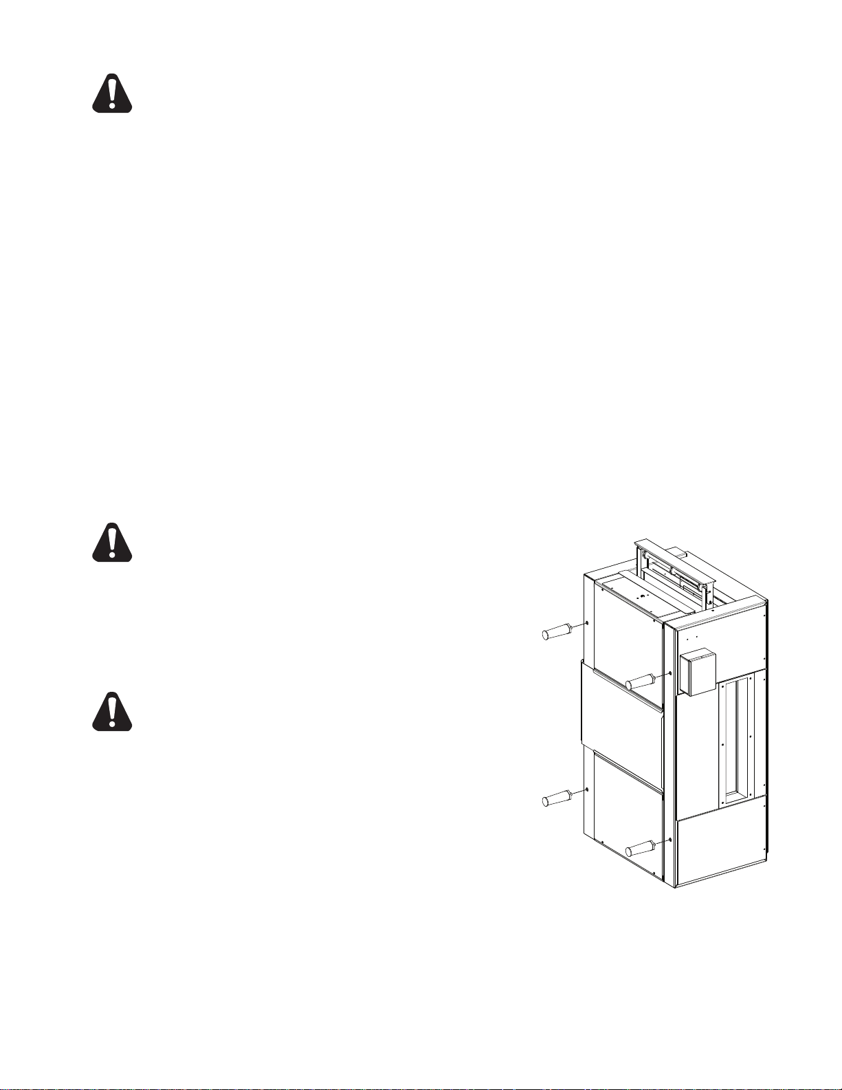
ASSEMBLY AND INSTALLATION
The unit was shipped with certain assembly required.
DO NOT PLACE THE UNIT ON ITS SIDE. FAILURE
TO COMPLY MAY RESULT IN DAMAGE TO
EQUIPMENT.
To attach the four 4 legs, with assistance place the unit on
its end as shown (damage to the elements can occur when
the unit is placed on its side) insert the legs by screwing
them into the weld nuts located on the bottom of the unit.
When completed and with help, carefully turn the unit
upright.
NEVER OPERATE UNIT WITHOUT PROPER LEGS
IN PLACE.
Install unit in its operating position. Level unit by adjusting
the feet. Both ends must be at least 6" from any vertical
combustiblesurface.Allowsufcientspaceforoperating
personnel.
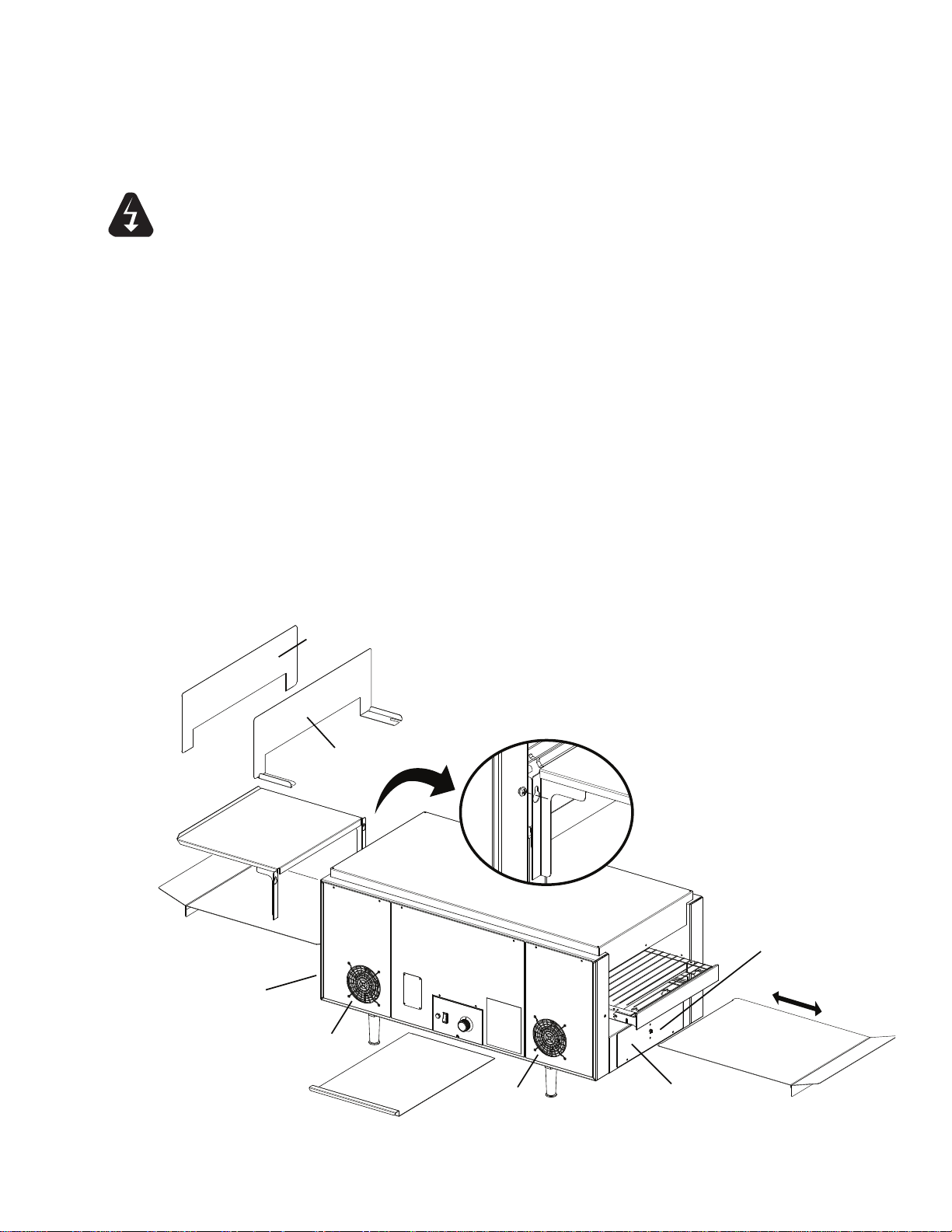
The Unload Tray has a keyhole slot on the tray that will
slide over the two screw heads on the end of the toaster as
shown int the Toaster Components Iluustration.
The crumb tray slides into each end of the toaster under
the conveyor. The slot is formed by two pieces of metal on
each side, under the toaster. They keep the interior of the machine clean
andreectheatawayfromthecontrolsandbackuptothesandwiches.
A layer of aluminum foil on the tray (check that it does not interfere with the conveyor) will make the
traymorereectiveandmakecleanupeasier.
LEG INSTALLATION
4
Page 5
ASSEMBLY AND INSTALLATION continued
UNLOAD TRAY
TYPICAL TOASTER COMPONENTS
IL1151A
CRUMB TRAY
CRUMB TRAY
HI-LIMIT RESET SWITCH
CLEAN
OPERATE
CRUMB TRAY
LOWER
AIR
INTAKE
ACCESS PANEL
ACCESS PANEL
AIR
INTAKE
“The Bake” Bracket
“The Bake” SIGN
WARNING
ELECTRICAL
CONNECTION
Have an electrician connect input power to the unit(s) in accordance with local electrical
codes. A connection terminal block is located inside an electrical box on the control side of
the unit. CORD & PLUG IS NOT PROVIDED.
VERIFY THE GROUND (EARTH) CONNECTION IS PROPERLY WIRED. NEVER
CONNECT UNIT TO POWER WITHOUT PROPER GROUND CONNECTIONS.
IMPROPER GROUND MAY RESULT IN SEVERE INJURY OR FATALITY.
MAKE SURE ALL INPUT POWER IS OFF BEFORE INSTALLING/REMOVING ANY
PARTS.
BEFORE INSTALLING UNIT, HAVE YOUR ELECTRICIAN CHECK WITH LOCAL
POWER COMPANY TO DETERMINE ACTUAL VOLTAGE AT THE STORE.
Before applying input power to the unit, check elements for breakage. DO NOT apply power to the
unit if a any elements are broken. If no broken elements are found, apply input power by switching
the ON/OFF toggle to the ON position. Turn conveyor belt speed control to the maximum setting
and check all elements and conveyor for proper operation.
Allow approximately 5 to 10 minutes for the twin-fan cooling system to come on. Check the air
intakefanareashownbelow,makingsurethereisasufcientowofairintotheunit.Restricting
theairowwillcausetheunittorunhotterthendesignedcausingdamagetotheunit.
If all heater and conveyor systems are operating properly, turn the master ON/OFF switch to the
OFF position and allow unit to cool. The fans will continue to circulate cool air throughout the unit
until the internal temperatures have been decreased.
If a problem is discovered during start up procedures, immediately turn the Master ON/OFF switch
to the OFF position and call the Star Service Help Desk at 1-800-807-9054.
5
Page 6
TOASTER
TOASTER
STACKING LEGS
(QTY 4)
IL1152
DRILL THROUGH
HOLES
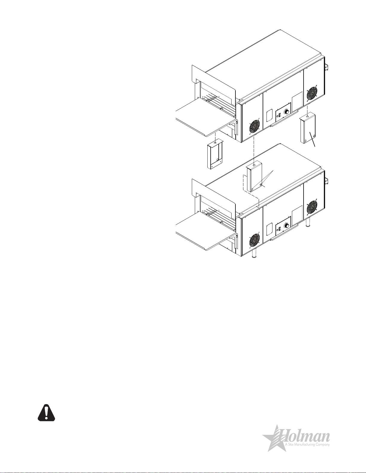
STACKING TOASTERS
When stacking two Holman QT14/
QT14B Conveyor Sandwich Toasters
a QT14 Stacking Legs Kit (part no.
PS-Z8977) MUST be used to prevent
overheating of the control box of the
top toaster.
1. Unplug BOTH UNIT power
cords from the wall receptacle,
and allow to cool.
2. Once cooled, stand the top unit
on end and remove all 4 feet.
Save them for possible future
use.
3.
Take one of the four (4) stacking
legs and bolt it in place of
previously removed leg.
T
ighten using wrench. Install
the remaining three.
4. Stand unit in its usable position
and verify the legs are stable.
5. Place the upper unit on top
of the other toaster, with the
controls facing the same
direction and lined up together.
6. Once in place, using a #29-drill
bit (.136"), drill holes into the
lower toaster by going through
the drill holes in the stacking leg
as shown. Do this in all four (4)
places.
Insert screws
7.
(provided)
holes
securing the two units together. Continue
until all four (4) are complete.
8. Plug in units and test for proper operation.
into the mounting
CAUTION
DAILY OPERATION
1. Turn On/Off switches to the ON position and variable speed control to the desired setting.
Allow 30-40 minutes for complete machine warm up.
2. Adjust speed as required during operation to achieve a good bake.
3. When done for the day, turn the On/Off switch to the OFF position. The conveyor
will
stop and the elements will go off. The two fans will continue to run to cool the machine.
The fans are controlled by a thermostat and will stop when the elements are cooled.
DO NOT begin to service or clean the machine until the fans have stopped.
CAUTION: Some parts of the machine will still be warm.
Refer to the Troubleshooting section if the machine is not performing as expected.
CERTAIN SURFACES ARE EXTREMELY HOT DURING OPERATION AND CARE
SHOULD BE TAKEN WHILE USING THIS UNIT.
6
Page 7
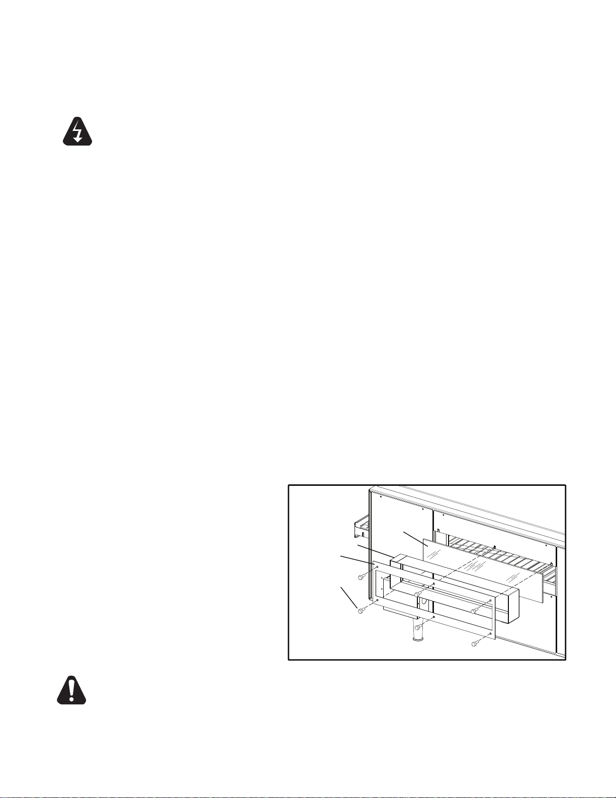
THUMBSCREWS
p/n:2C-200015
RETAINER
SPACER
GLASS
IL1154
WARNING
CLEANING
Preventive maintenance for your toaster consists of the following recommended cleaning procedures.
To keep your unit in its top operating condition, these steps should be performed on a daily, weekly or
as indicated.
Turn power off and allow cooling fans to run until the control box is cooled off. A thermostat in the
control box controls the fans.
DISCONNECT UNIT FROM POWER SUPPLY OR TURN POWER OFF AT WALL
BREAKER.
DAILY
1. Turn main power switch to the OFF position. Disconnect unit from power source and
allow to cool.
2. Using a mild detergent, wipe exterior surfaces, clean with a damp cloth.
a. For lightly soiled build-up, clean with a damp cloth.
b. For heavily soiled build-up, use a soft damp cloth and mild detergent.
DO NOT use caustic cleaners.
3. Remove
water.
4. Remove all three (3) crumb trays.
DO NOT use caustic cleaners.
Place trays back in place prior to putting unit back into operation.
5. Check air intake area for dust and grease. To clean, vacuum and wipe with a dry cloth. (daily)
DO NOTspraycleaninguidsintotheairintakeorcookingchamber.
This may result in component failure.
6. If your unit has the glass window, carefully remove and clean the window. Remove the
thumbscrews securing the window assembly. Remove the window retainer, spacer, and the
piece of glass.
W
7.
the unload tray by lifting it out of position. Clean using mild detergent and warm
Clean crumb trays by wiping with a damp cloth and mild detergent.
ash with hot, soapy water. Reassemble.
Reconnect power.
CAUTION
THE GLASS THAT IS SUPPLIED WITH SOME OVENS IS SPECIFICALLY DESIGNED
FOR IT. DO NOT SUBSTITUTE ANY OTHER GLASS PRODUCTS IN ITS PLACE.
Toaster Window Access (certain units)
NEVER OPERATE THE OVEN WITHOUT THE GLASS. NEVER ATTEMPT TO TOUCH
OR REMOVE THE GLASS WHILE THE OVEN IS HOT. ALLOW THE OVEN TO COOL
FOR SEVERAL HOURS BEFORE STARTING THE CLEANING PROCEDURE.
7
Page 8
CLEANING continued
IL1153
WEEKLY
1. Turn main Power switch to the OFF position. Disconnect unit from power source and
allow to cool.
2.
Perform daily cleaning procedures.
3. Using a damp cloth, wipe clean the fan guard located on the control box cover
under the unit.
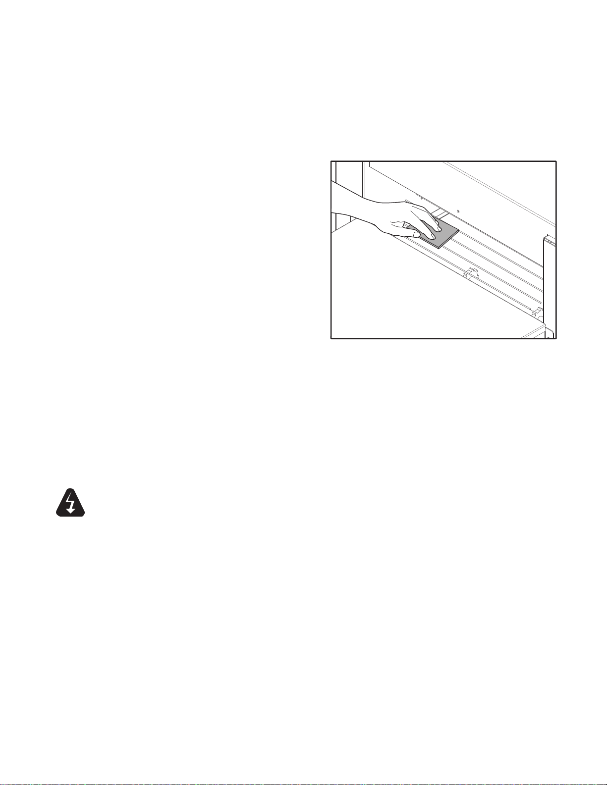
CONVEYOR BELT CLEANING
PROCEDURES
4. Reconnect power or turn power back on.
5. Switch the ON/OFF switch to the ON
position, and turn conveyor to its fastest
setting.
6.
With the conveyor turned on and the crumb
trays in place, take a wire grill brush or dry
abrasive pad, clean the exposed surface
of conveyor belt by passing the brush or
pad, back and forth across the surface
of the conveyor belt as the belt moves
past. continue until the entire belt is clean.
Make sure the crumb tray is installed; this
will minimize the amount of particles that
fall into the toaster.
7. When the Conveyor Belt is clean, take a damp cloth and wipe the conveyor, removing any
loose particles on the belt surface. Turn Conveyor OFF.
8. Remove the Crumb Trays by sliding out from beneath the conveyor belt and discard soiled
aluminum foil. If cleaning is necessary, use a damp cloth and mild detergent.
NOT use caustic cleaners.
DO
DO NOT RUN CONVEYOR OVEN WITHOUT CRUMB TRAYS INSTALLED.
9. Cover crumb trays with clean aluminum foil and put back to its correct position.
WARNING
DO NOT IMMERSE OR LET THE UNIT STAND IN WATER.
DO NOT HOSE DOWN THE UNIT OR THE TABLE/COUNTER IF THE UNIT IS ON
THE TABLE/COUNTER.
KEEP AWAY FROM RUNNING WATER.
8
Page 9

CLEANING continued
IL1156
DRIVE MOTOR
MOUNTING SCREWS
DRIVEN SPROCKET
DRIVE SPROCKET
UNLOAD TRAY
IL1155
CHAIN
MONTHLY
1. Turn power switch to the OFF position. Disconnect unit from power source and
allow to cool.
2. Perform daily & weekly cleaning procedures.
3. Working from the power supply side of the oven, locate the side panel, remove two
screws holding panel in place and remove panel. Drive chain is now exposed.
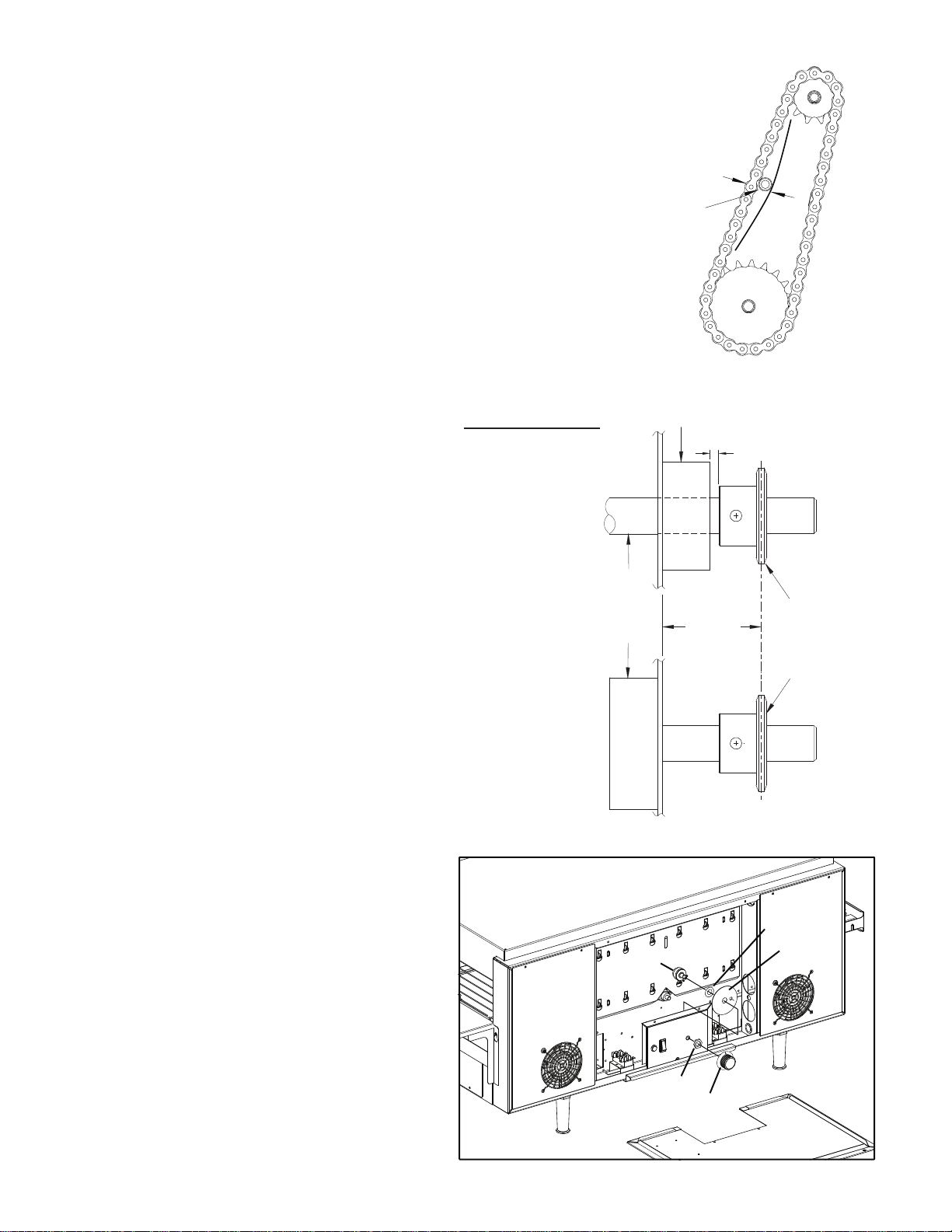
4. Check drive chain tension.
a. When properly adjusted, chain will
have about 1/8" play but will not
sag.
See Chain Tension Illustration on
page 12.
To adjust drive chain tension,
b.
locate
the drive motor mounting
screws (see illustration). Loosen
screws holding drive motor in
place and slide drive motor
forward or backward to adjust
chain tension. With proper chain
tension, retighten motor screws.
c. Following the procedures on page
12, Lubricate drive chain and
sprocket teeth with a high temp lubricant part no. 1P-Z8914.
5.
Clean air intake on the side of the unit by vacuuming any dust and debris built up on the fan
grill.
6.
Remove screws holding the control side panels in place (as shown below). Carefully lift panel
up and out. Vacuum any dust and debris from inside the unit, being sure to clean the fan
blades and inside of unit, repeat opposite side.
7. Replace all panels when completed. CHECK NO WIRES GET PINCHED AS THE PANELS
ARE REPLACED. ALSO, CHECK ANY WIRES AROUND THE MOTOR TO MAKE SURE
THEY DO NOT INTERFERE WITH THE SPROCKETS.
8. For exterior portions of unit that are heavily soiled, an abrasive pad may be used for cleaning.
Besuretopassthepadinthedirectionofthegraininthemetaltomaintainthesurface'snish.
Lightly soiled surfaces may be cleaned with a damp cloth and mild cleaner.
9. Reconnect unit to power
supply and test for proper
operation.
IF ASSISTANCE
IS REQUIRED, CALL THE
STAR SERVICE HELP DESK
AT 1-800-807-9054.
9
Page 10

MAINTENANCE & REPAIRS
Retainer
Element
Side Panels
Access Panel
IL1157
IL1158
Side Panel
Air Intake Grill
Fan Motor
IL1159
Drive Motor
Drive Sprocket
Chain
Driven Sprocket
A. REPLACING ELEMENT
NOTE: Replace one element at a time.
1) DISCONNECT POWER SOURCE.
2) Remove both the left and right side panels,
by removing the truss head screws. Pull the
top of each panel out slightly and lift up.
3) Remove element wires which are requiring
replacement from its terminal block connection.
4) Loosen the Element Retainer and move it
upward and tighten.
5) Gently, pull defective element out of unit.
6) Slide sipping straws on the element wires for
an easier installation. Guiding the wire &
element into position
7) Connect wires to the terminal blocks and tug
lightly on the wire to ensure good connection.
8) Loosen screw(s) holding the retainer secure
and slide it back into position, to secure
element in place.
9) Install each side panel
10) Connect unit to power source and test unit for
proper operation.
B. REPLACING FAN MOTOR
1) DISCONNECT POWER SOURCE.
2) Remove the side panel with the fan that needs
replaced.
3) Unplug power supply cord from fan motor.
4) Remove (4) screws, which hold fan motor and
grill to the side panel and remove fan.
5) Put replacement motor and grill in place and
secure to the side panel with screws
previously removed.
6) Reconnect power supply cord to fan motor.
7) Replace back panel and enclosure. Fasten with
screws removed in step 2, being sure to keep
wires away from the fan motor.
8) Connect unit to power source and test unit for
proper operation.
C. REPLACING BELT DRIVE MOTOR
1) DISCONNECT POWER SOURCE.
2) Remove the side panel & access panel
exposing the drive chain, sprockets & drive
motor
3) Remove sprocket from motor shaft, using an
Allen wrench and loosening the set-screw.
4) Remove the wires from terminal block
connecting the drive motor.
Note how the old motor is wired for
replacement. For reference, use the black
and white wires for 208V units and the black
and blue wires for 240V units. The unused wire should be taped on the end and bundled with the existing
wires so it will not get tangled in any moving parts.
5) Remove screws holding motor in place and remove motor from unit.
6) Install the new motor in place and attach loosely with mounting screws.
10
Page 11
MAINTENANCE PROCEDURES continued
1/4”
Bearing
1/16” Space
Driven
Spocket
Drive
Sprocket
Driven
Shaft
Drive
Motor
Sprocket
Spacing
IL1160
IL1162
SPEED CONTROL
WASHER
INSTALLATION
NUT
KNOB
7) Install sprocket on motor shaft & chain after aligning them.
See Sprocket Alignment Illustration.
NOTE: The two sprockets must line up FLUSH with each other, so the
chain does not twist during operation. Also the hub is installed
closest to the motor.
8) Slide motor until the drive chain has about 1/4” slack when
lightly pushed at the center of its top open run.
See Chain Tension Illustration.
9) Tighten screws to secure motor.
10) Rewire leads same as removed in step 4.
11) At this time you may plug unit in and test for proper operation prior
to reinstalling previously removed panels.
12) If unit is working correctly, turn unit off and unplug until completed
13) Reinstall side & access panels.
Reinstall the crumb trays.
14) Connect unit to power source and test again for proper operation.
D. LUBRICATE THE CHAIN & SPROCKETS EVERY 6 MONTHS
1) DISCONNECT UNIT FROM POWER SOURCE.
2) Remove the side panels which exposes chain drive.
3) Check for proper Chain Tension, See Chain Tension Illustration.
4) Using an extreme pressure, synthetic chain lubricant with a
temperature range up to 400°F.
Apply liberally onto chain and sprockets.
This grease is available separately as part no. 1P-Z8914.
Call 1-(800) 807-9054 to order.
5) Replace side panels, Reconnect power source and test unit.
CHAIN TENSION
E. REPLACING SPEED CONTROL
1) DISCONNECT POWER SOURCE.
2) Remove the speed control knob and the locking nut holding the
speed control in place.
3) Remove side panel, by removing the truss
head screws. Pull the top of the panel out slightly
and lift up.
4) Remove the wires from the control and
insert wires for the new speed control into the same positions as
shown on the wiring diagram.
5) Install the washer onto the shaft of the new speed control, followed
by the installation.
6) When mounting the speed control in the
side panel be sure to position the
anti-rotation pin in the slot as shown.
7) Tighten the speed control assembly by using
the locking nut, followed by the control knob.
8) Reinstall the side panel and tighten with the
screws previously removed.
9) Connect unit to power source and test unit for
proper operation.
SPROCKET ALIGNMENT
REPLACING SPEED CONTROL
11
Page 12

TROUBLESHOOTING GUIDE
IL1161
Drive
Sprocket
Chain
Driven
Sprocket
A. UNIT WILL NOT HEAT, CONVEYOR BELT WILL NOT MOVE.
1) Be sure the main circuit breaker is switched to the ON position and there is power to the outlet.
2) Check to see if the toaster is plugged in and all controls are turned to the ON position.
3) Be sure the Hi-Limit Reset Button is pushed in.
4) Call the Star Service Help Desk at 1-800-807-9054.
B. UNIT WILL NOT HEAT, CONVEYOR TURNS PROPERLY.
1) Check to see if the heat controls have been turned to the maximum setting.
2) Press the Hi-Limit Reset Button located on the end under the conveyor belt.
If this reactivates the heater tubes, see Hi-Limit Reset Section below.
3) Call the Star Service Help Desk at 1-800-807-9054.
C. HI-LIMIT (HEAT) RESET.
Your Holman conveyor toaster is equipped with an automatic activated temperature limit switch which interrupts
the heater tube connections if the air temperature in the control box exceeds 190°F (88°C) This limit switch can
be reset manually by pushing the button in the center of the switch which is located on the right side under the
conveyor belt. See Oven Components on Page 7 for location. Unit will not reset until internal temperature has
fallen below 190°F (88°C).
NOTE: THE HI-LIMIT SWITCH CAN BE ACTIVATED IF THERE IS NOT A PROPER AMOUNT OF
AIR FLOW BEING GENERATED BY THE COOLING FAN. IF THIS OCCURS:
1) DISCONNECT UNIT FROM POWER SOURCE.
2) Check to see if the air intake area is free of dust, grease or other obstructions.
3) Checktoseeifcrumbtrays(heatreectors)areinplace.
If the Hi-Limit Switch can not be reset, call the Star Service Help Desk at 1-800-807-9054.
CAUTION
D. CONVEYOR WILL NOT TURN, UNIT HEATS PROPERLY.
To check for mechanical binding:
1) DISCONNECT UNIT FROM POWER SOURCE.
2) Check to see if there are obstructions in the conveyor
3) Check power supply & terminal blocks for loose or
4) Check to see if the two sprockets are properly
5) Remove side panel exposing the drive motor
E. COOLING FAN DOES NOT START
1) Check fan blade for obstruction, or broken blades.
2) Check electrical connections are secure and complete & the Hi-Limit Switch is working properly.
3) If only one of the two fans are working, and all connections are good, replace the fan.
Refer to REPLACING FAN MOTOR in the previous section.
4) If both fans are not working, chances are the fan switch needs replacing.
3) Call the Star Service Help Desk at 1-800-807-9054, as the fan switch and or fan motor MAY need
replacing.
NEVER OPERATE UNIT WITHOUT CRUMB TRAYS IN POSITION AS THIS CAUSES
OVERHEATING IN THE CONTROL BOX.
system that may cause a jam. If so, remove
obstruction.
disconnected wires.
aligned. Refer to SPROCKET ALIGNMENT previous
section.
sprockets, see illustration. Manually move conveyor
belt to check for mechanical binding. If conveyor belt
moves freely, call the Star Service Help Desk
at 1-800-807-9054. The drive motor or speed control
may have to be replaced.
12
Page 13

Part# 2M-4497-2 05/06 RB
The foregoing warranty is in lieu of any and all other warranties expressed or implied and constitutes the entire warranty.
FOR ASSISTANCE
Should you need any assistance regarding the Operation or Maintenance of any Star equipment; write, phone, fax or email our Service Department.
In all correspondence mention the Model number and the Serial number of your unit, and the voltage or type of gas you are using.
ALL:
* Pop-Up Toasters
* Butter Dispensers
* Pretzel Merchandisers
* Pastry Display Cabinets
* Nacho Chip Merchandisers
* Accessories of any kind
* Sneeze Guards
* Pizza Ovens
* Heat Lamps
* Pumps
Visit our Website at:
www.star-mfg.com Email: service@star-mfg.com
THOROUGHLY INSPECT YOUR UNIT ON ARRIVAL
This unit has been tested for proper operation before leaving our plant to insure delivery of your unit in perfect condition. However, there are instances in
which the unit may be damaged in transit. In the event you discover any type of damage to your product upon receipt, you must immediately contact the
transportation company who delivered the item to you and initiate your claim with same. If this procedure is not followed, it may affect the warranty
status of the unit.
LIMITED EQUIPMENT WARRANTY
All workmanship and material in Star products have a one (1) year limited warranty on parts & labor in the United States and Canada. Such warranty is
limited to the original purchaser only and shall be effective from the date the equipment is placed in service. Star's obligation under this warranty is limited
to the repair of defects without charge, by the factory authorized service agency or one of its sub-agencies. Models that are considered portable (see below)
should be taken to the closest Star service agency, transportation prepaid.
> Star will not assume any responsibility for loss of revenue.
> On all shipments outside the United States and Canada, see International Warranty.
* The warranty period for the JetStar six (6) ounce & Super JetStar eight (8) ounce series popcorn machines is two (2) years.
* The warranty period for the Chrome-Max Griddles is five (5) years on the griddle surface. See detailed warranty provided with unit.
* The warranty period for Teflon/Dura-Tec coatings is one year under normal use and reasonable care. This warranty does not apply if damage occurs to
Teflon/Dura-Tec coatings from improper cleaning, maintenance, use of metallic utensils, or abrasive cleaners. This warranty does not apply to the
“non-stick” properties of such materials.
> This warranty does not apply to "Special Products" but to regular catalog items only. Star's warranty on "Special Products" is six (6) months on parts
and ninety (90) days on labor.
> This warranty does not apply to any item that is disassembled or tampered with for any purpose other than repair by a Star Authorized Service Center or
the Service Center's sub-agency.
> This warranty does not apply if damage occurs from improper installation, misuse, wrong voltage, wrong gas or operated contrary to the Installation and
Operating instructions.
> This warranty is not valid on Conveyor Ovens unless a "start-up/check-out" has been performed by a Factory Authorized Technician.
PARTS WARRANTY
Parts that are sold to repair out of warranty equipment are warranted for ninety (90) days. The part only is warranted. Labor to replace the part is
chargeable to the customer.
SERVICES NOT COVERED BY WARRANTY
PORTABLE EQUIPMENT
Star will not honor service bills that include travel time and mileage charges for servicing any products considered "Portable" including items listed below.
These products should be taken to the Service Agency for repair:
1. Travel time and mileage rendered beyond the 50 mile radius limit
2. Mileage and travel time on portable equipment (see below)
3. Labor to replace such items that can be replaced easily during a daily cleaning
routine, ie; removable kettles on fryers, knobs, grease drawers on griddles, etc.
4. Installation of equipment
5. Damages due to improper installation
6. Damages from abuse or misuse
7. Operated contrary to the Operating and Installation Instructions
8. Cleaning of equipment
9. Seasoning of griddle plates
10. Voltage conversions
11. Gas conversions
12. Pilot light adjustment
13. Miscellaneous adjustments
14. Thermostat calibration and by-pass adjustment
15. Resetting of circuit breakers or safety controls or reset buttons
16. Replacement of bulbs
17. Replacement of fuses
18. Repair of damage created during transit, delivery, &
installation OR created by acts of God
* The Model 510FD Fryer.
* The Model J4R, 4 oz. Popcorn Machine.
* The Model 518CMA & 526CMA Cheese Melter.
* The Model 12MC & 15MC & 18MCP Hot Food Merchandisers.
* The Model 12NCPW & 15NCPW Nacho Chip/Popcorn Warmer.
* All Hot Dog Equipment except Roller Grills & Drawer Bun Warmers.
* All Nacho Cheese Warmers except Model 11WLA Series Nacho Cheese Warmer.
* All Condiment Dispensers except the Model HPDE, & SPDE Series Dispenser.
* All Specialty Food Warmers except Model 130R, 11RW Series, and 11WSA Series.
* All QCS/RCS Series Toasters except Model QCS3 & RCS3 Series.
13
Page 14

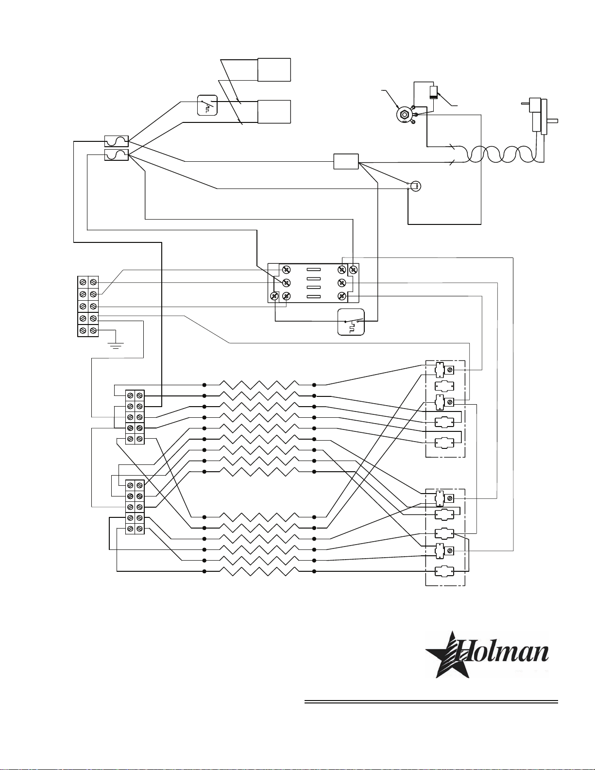
MODEL:
QT14B-Window, 208/220/240V, 1Phase
w/Potentiometer Speed Control
THIS DRAWING CONTAINS INFORMATION CONFIDENTIAL TO STAR MFG. INT'L. INC.
NO REPRODUCTION OR DISCLOSURE OF ITS CONTENTS IS PERMITTED.
STAR MANUFACTURING INTERNATIONAL INC.
SK2185 Rev -
6/05/2006
®
FAN
FAN SWITCH
PILOT LIGHT
ON/OFF
FUSE 2
FUSE 1
DRIVE MOTOR:
USE BLK/WHT FOR 208V
USE BLK/BLU FOR 240V
4
3
13
14
15
17
18
19
20
21
23
22
TGGT 14GA
B-14 GA
B-14GA
W-14GA
B-14GA
W-14GA
B-14GA
B-14GA
W-14GA
IS 18GA
FAN WIRE IS 18GA
W-14GA
15
14
12
MOTOR WIRE
DIODE
500 OHM
POT
W-14GA
FAN
TGGT 14GA
L2
L1
G
6-3 SEOW
16
24
1
2
56 78
11
9
10
B-8GA
W-8GA
W-14GA
L2
L1
A1
T2
T1
A2
L2
L1
A1
T2
T1
A2
B-14GA
B-10GA
W-10GA
WINDOW SIDE
CONTROL SIDE
TOP HEATERS
(5 SERIES PAIRS IN PARALLEL)
BOTTOM HEATERS
(3 SERIES PAIRS IN PARALLEL)
B-10GA
W-10GA
W-10GA
B-10GA
TERMINAL BLOCK A
TERMINAL BLOCK B
RESET
SWITCH
B-14GA
B-14GA
14
Page 15
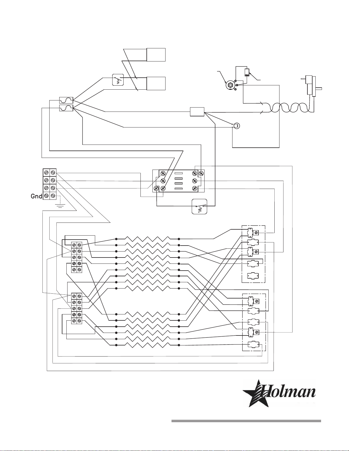
FAN
FAN SWITCH
PILOT LIGHT
RESET
ON/OFF
FUSE 2
SWITCH
FUSE 1
DRIVE MOTOR:
USE BLK/WHT FOR 208V
USE BLK/BLU FOR 240V
10
11
13
14
15
17
18
19
20
21
23
W-14GA
22
TGGT 14GA
B-14 GA
B-14GA
B-14GA
W-14GA
R-14GA
B-14GA
W-14GA
B-14GA
W-14GA
B-14GA
IS 18GA
FAN WIRE IS 18GA
W-14GA
15
14
BOTTOM HEATERS
CONTROL SIDE
TOP HEATERS (9)
(3 SERIES TRIPLES IN PARALLEL WITH
3 SERIES BOTTOM PAIRS)
WINDOW SIDE
W-10GA
R-10GA
BLACK-10GA
TERMINAL BLOCK A
(HEATER WALL SIDE)
TERMINAL BLOCK B
(PANEL SIDE)
TERMINAL BLOCK C
(OUTBOARD SIDE)
TERMINAL
BLOCK D
2
1
3
4
5
6
7
8
9
2
1
3
4
5
6
2
1
3
4
5
6
2
1
3
4
5
6
7
8
9
2
1
3
8
16
12
MOTOR WIRE
DIODE
500 OHM
POT
B-14GA
B-14GA
7
W-14GA 9
FAN
TGGT 14GA
L3
N
Gnd
L2
L1
BLUE-10GA
5
4
6
24
1L1
3L2
5L3
6T3
4T2
2T1
MODEL:
QT14, 3 Phase Y
THIS DRAWING CONTAINS INFORMATION CONFIDENTIAL TO STAR MFG. INT'L. INC.
NO REPRODUCTION OR DISCLOSURE OF ITS CONTENTS IS PERMITTED.
STAR MANUFACTURING INTERNATIONAL INC.
SK2193 Rev -
2/06/2006
®
15
Page 16
L2
L3
2E(GE)-135672
L1
FAN
FAN SWITCH
PILOT LIGHT
RESET
ON/OFF
FUSE 2
SWITCH
FUSE 1
DRIVE MOTOR:
USE BLK/WHT FOR 208V
USE BLK/BLU FOR 240V
13
14
15
20
21
23
B-14GA
22
TGGT 14GA
19 B-14 GA
B-14GA
B-14GA
W-14GA
17 B-14GA
18 W-14GA
B-14GA
16 W-14GA
10 B-14GA
IS 18GA
FAN WIRE IS 18GA
W-14GA
15
14
BOTTOM HEATERS
CONTROL SIDE
TOP HEATERS (9)
(3 SERIES TRIPLES IN PARALLEL WITH
3 SERIES BOTTOM PAIRS)
WINDOW SIDE
TERMINAL BLOCK A
(HEATER WALL SIDE)
TERMINAL BLOCK B
(PANEL SIDE)
TERMINAL BLOCK C
(OUTBOARD SIDE)
TERMINAL
BLOCK D
2
1
3
4
5
6
7
8
9
2
1
3
4
5
6
2
1
3
4
5
6
2
1
3
4
5
6
7
8
9
B-10GA 1
W-10GA 2
R-10GA 3
6
5
4
W-14GA 8
11
24 B-10GA
25 R-10GA
26 W-10GA
MOTOR WIRE
DIODE
500 OHM
POT
12 W-14GA
B-14GA 7
R-14GA 9
FAN
TGGT 14GA
MODEL:
QT14, 3 Phase Delta - POT Control
THIS DRAWING CONTAINS INFORMATION CONFIDENTIAL TO STAR MFG. INT'L. INC.
NO REPRODUCTION OR DISCLOSURE OF ITS CONTENTS IS PERMITTED.
STAR MANUFACTURING INTERNATIONAL INC.
SK2194 Rev A
8/07/2006
®
16
Page 17

Page 18
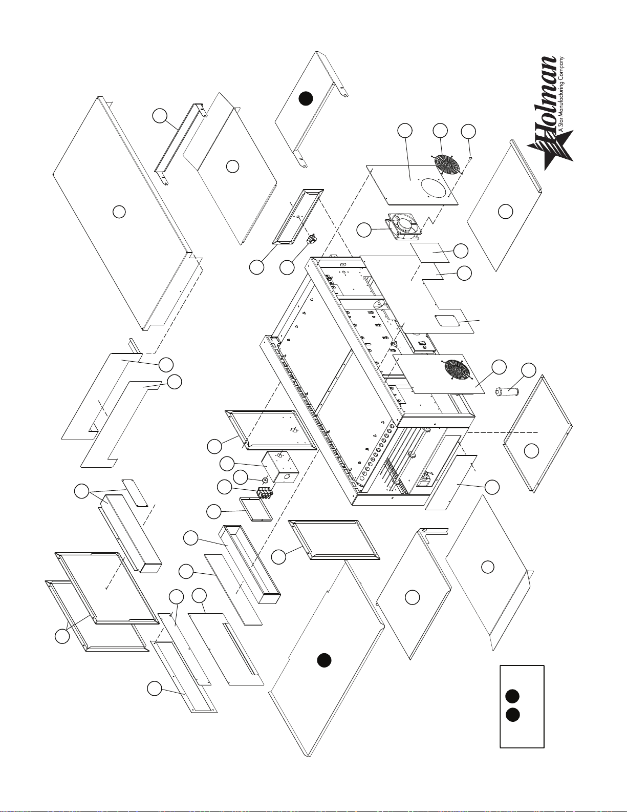
28
3
3
27
26
25
24
23
22
21
20
19
18
17
16
15
14
13
12
Nameplate
11
10
9
8
7
6
5
4
1
2
31
32
MODEL:
QT14B
SK2186 Rev. D 4/14/09
33
34
33
34
OPTIONAL
ACCESSORY PARTS
29
30
Page 19

Description
Per
Quantity
Part
Number
Fig
No.
19 GE-Z9636 1 PANEL - POWER INPUT
20 GE-402709 1 ELECTRICAL BOX (POWER INPUT)
21 2K-200464 5 BUSHING, WIRE RING 7/8”
22 SP-115402 1 TERMINAL BLOCK - MAIN POWER
23 GE-402710 1 ELECTRICAL BOX COVER
24 GE-101390 1 WINDOW SPACER
25 2Q-200588 1 WINDOW - NEO SARAMA
26 GE-101028 1 PANEL - LOWER BACK
27 GE-402689 1 PANEL - UPPER BACK
28 GE-402631 1 WINDOW RETAINER - OUTSIDE
29 GE-Z10172 1 WINDOW BLANKOFF SIDE PANEL
GE-Z9911 1 SIDE PANEL, CENTER PLAIN
Serial No. COQT0507B0001-20, 31-40 and above
30 GE-Z10173 1 WINDOW BLANKOFF BOX
GE-Z9902 1 ACCESS COVER PLATE
Serial No. COQT0507B0001-20, 31-40 and above
31 2M-200816 1 BAKE AID MAGNET
32 GE-402729 1 BAKE AID BRACKET
ACCESSORIES
33 QTEXIT14 - EXIT SHELF FOR QT14 QUIZNO’S - 14 X 28
34 QTENTRY7 - ENTRY SHELF FOR QT14 QUIZNO’S
NI 2E-Z9567 2 FAN CORD
NI 2E-200573 1 CONTRACTOR/RELAY - 3 PHASE OVENS
NI 2E-Z9782 2 TERMINAL BLOCK - ESE2 3 PHASE
NI = NOT ILLUSTRATED
QT14B Holman Conveyor Toaster
Description
Per
Quantity
Part
Number
Fig
No.
1 GE-100991 1 TOP COVER
2 GE-402610 1 CONVEYOR END GUARD
3 GE120303 2 CRUMB TRAY
4 GE-Z9594 1 PANEL, CONTACTOR SIDE w/RESET
5 2E-200566 1 SWITCH, OVERTEMP (RESET)
6 2U-200577 2 COOLING FAN - 240V HIGH OUTPUT
8 2R-200562 1 FAN GUARD - COOLING FAN
7 GE-Z9598 1 PANEL - FAN OFFSET RIGHT
9 2C-200048 8 SCREW, 10-24 X 1/2” SLOT HEX
10 GE-402654 1 CRUMB TRAY - LOWER
12 GE-Z9596 1 PANEL - CONTROL SIDE
13 GE-Z9597 1 PANEL - FAN OFFSET LEFT
14 2A-Z0314 4 LEG - 4”
11 2M-Z9631 1 LABEL, QUIZNOS
15 GE-Z9633 2 CONTROL BOX COVER
16 GE-Z9593 1 PANEL, MOTOR SIDE
17 GE-100944 1 UNLOAD TRAY
18 GE-Z9635 1 PANEL - PLAIN SIDE
Rev. I 4/14/09
Page 20

57
62
63
64
66
67
68
36
70
69
MODEL:
QT14B
SK2187 Rev. B 12/13/06
35
36
37
36
38
40
39
41
42
43
44
45
46
47
48
49
50
51
54
55
56
58
59
60
61
65
52
53
Page 21

Description
Per
Quantity
Part
Number
Fig
No.
51 2E-Z8966 2 CONTRACTOR/RELAY - 1 PHASE OVENS
54 2E-200574 1 SWITCH, FAN (COOLDOWN)
52 2E-200597 1 FUSEHOLDER - 2 POSITION, TYPE G
53 2E-Z8405 2 FUSE - 15A TYPE G
55 HG-402144 1 BRACKET, FAN SWITCH
56 GE-Z9359 1 SPEED CONTROL POTENETIOMETER (500 OHM)
57 2E-200180 1 INSULATION, SWITCH, POTENEIOMETER
59 GE-Z9595 1 PANEL, FRONT CONTROL w/SWITCHES
59 2M-Z9630 1 LABEL, MAIN CONTROL
60 1 NUT, 3/8"-32 NEF, COMES WITH FIG. NO 52
61 2R-200761 1 KNOB, SPEED CONTROL
62 2E-Z9592 1 SWITCH, MAIN ON/OFF
63 2J-Z2329 1 PILOT LIGHT - RED
64 2E-Z9571 2 TERMINAL BLOCK - 12 POSITION
65 2A-101257 1 RETURN SHAFT ASSY (W/SPROCKETS)
66 GE-198102 6 HEATER TUBE, 675W 208V BOTTOM, 1PH & 3PH
GE-198104 6 HEATER TUBE, 675W 240V BOTTOM, 1PH
GE-198106 6 HEATER TUBE, 700W 220V BOTTOM, 1PH & 3PH
67 GE-198103 10 HEATER TUBE, 375W 208V TOP, 1PH
GE-198105 10 HEATER TUBE, 375W 240V TOP, 1PH
GE-198107 10 HEATER TUBE, 375W 220V TOP, 1PH
GE-198108 9 HEATER TUBE, 417W 380V TOP, 3PH
GE-198109 9 HEATER TUBE, 417W 208V TOP, 3PH
68 GE-402359 1 HEATER TUBE RETAINER - LARGE
69 GE-402651 2 HEATER TUBE RETAINER - SMALL
70 2A-200672 3 SHAFT COLLAR - 3/8”
NI PS-101595 1 HEATER TUBE KIT (ALL 16) 208V
NI PS-101596 1 HEATER TUBE KIT (ALL 16) 240V
NI PS-Z8977 1 STACKING KIT
NI 2E-Z9567 2 FAN CORD
NI 2E-200573 1 CONTRACTOR/RELAY - 3 PHASE OVENS
NI 2E-Z9782 2 TERMINAL BLOCK - ESE2 3 PH
NI 1P-Z8914 1 EXTREME PRESSURE MULTIPURPOSE SYNTHETIC
GREASE (80°F TO 400°F) , TUBE 8 oz.
NI = NOT ILLUSTRATED
QT14B Holman Conveyor Toaster
Description
Per
Quantity
Part
Number
Fig
No.
35 2C-200150 1 WASHER, 3/8”
38 2P-200652 1 SPROCKET DRIVEN -17 tooth 3/8 after COQT0301B0001
36 GB-112262 4 BEARING ASSY. 3/8” FLANGED
37 GE-101254 1 DRIVE SHAFT ASSY (W/SPROCKETS)
39 2P-200646 1 SPROCKET DRIVE - 20 tooth 5/16 after COQT0301B0001
40 2P-150000 1 QT14 DRIVE CHAIN #25
2P-115362 1 SPROCKET DRIVEN -11 tooth 3/8 before COQT0301B001
41 PS-Z10285 1 CONVEYOR MOTOR LEFT TO RIGHT 50/60Hz
2P-200650 1 SPROCKET DRIVE -24 tooth 5/16 before COQT0301B001
2U-Z9658 1 MOTOR AC 11 RPM CCW
2P-200652 1 SPROCKET DRIVEN -17 tooth 3/8"
2P-200646 1 SPROCKET DRIVE - 20 tooth 5/16"
2C-Z10075 1 SCREW - 1/4-20X3/8
2A-Z10161 1 SPACER-STEEL
2M-Z10161 1 INSTRUCTIONS - QT14 DRIVE MOTOR REPLAC.
2U-Z9657 1 MOTOR AC 11 RPM CW
2P-200652 1 SPROCKET DRIVEN -17 tooth 3/8"
2P-200646 1 SPROCKET DRIVE - 20 tooth 5/16"
2C-Z10075 1 SCREW - 1/4-20X3/8
2A-Z10161 1 SPACER-STEEL
2M-Z10161 1 INSTRUCTIONS - QT14 DRIVE MOTOR REPLAC.
PS-Z10286 1 CONVEYOR MOTOR RIGHT TO LEFT 50/60Hz
PS-Z10285 INCLUDES: s/n COQT0307B0001 or after order parts separately
PS-Z10286 INCLUDES: s/n COQT0307B0001 or after order parts separately
NI 2R-200721 1 FAN BLADE - CONVEYOR MOTOR L-R
NI 2R-Z8879 1 FAN BLADE - CONVEYOR MOTOR R-L
42 GE-100715 1 BELT SUPPORT
43 GE-160031 1 CONVEYOR BELT W/ 3 LINKS - 82.5” LONG
44 2B-200618 1 CONVEYOR BELT LINK, 14”
45 2B-200620 3 CONVEYOR BELT SINGLE SPACE CLIP
46 2E-Z9570 2 TERMINAL BLOCK - 4 POS.
2E-Z9781 2 TERMINAL BLOCK - 5 POS. 3 PHASE
47 GE-402574 2 BEARING HOLDER
48 2P-200766 2 SPRING, BEARING
49 2P-200785 2 BEARING, SPRING LOADED
50 GE-101255 1 IDLER SHAFT ASSY (W/SPROCKETS)
Rev. i 4/14/09
Page 22

Page 23

Page 24

STAR MANUFACTURING GROUP
Star - Holman - Lang - Wells - Bloomeld
10 Sunnen Drive, St. Louis, MO 63143 U.S.A.
(800) 807-9054 (314) 781-2777
Parts & Service (800) 807-9054
www.star-mfg.com
 Loading...