

Page 1
®
®
®
®
CONVEYOR
TOASTER
MODEL
QCS1-350-120V
QCS1-500B-120V
Installation and
Operation
Instructions
2M-Z9777 Rev. A 6/22/2010
QCS1-350-120V
1
Page 2

2
These symbols are intended to alert the user to the presence of
important operating and maintenance instructions in the manual
accompanying the appliance.
RETAIN THIS MANUAL FOR FUTURE REFERENCE
NOTICE
Using any part other than genuine Star factory supplied parts relieves the
manufacturer of all liability.
Star reserves the right to change specications and product design without
notice. Such revisions do not entitle the buyer to corresponding changes,
improvements, additions or replacements for previously purchased
equipment.
Due to periodic changes in designs, methods, procedures, policies and
regulations, the specications contained in this sheet are subject to change
without notice. While Star International Holdings Inc., Company exercises
good faith efforts to provide information that is accurate, we are not
responsible for errors or omissions in information provided or conclusions
reached as a result of using the specications. By using the information
provided, the user assumes all risks in connection with such use.
MAINTENANCE AND REPAIRS
Contact your local authorized service agent for service or required maintenance.
Please record the model number, serial number, voltage and purchase date in the area below and have it ready when
you call to ensure a faster service.
SAFETY SYMBOL
Model No.
Serial No.
Voltage
Purchase Date
Business
8:00 am to 4:30 p.m. Central Standard Time
Hours:
Telephone: (800) 264-7827 Local (314) 781-2777
Fax: (800) 396-2677 Local (314) 781-2714
E-mail Parts@star-mfg.com
Service@star-mfg.com
Warranty@star-mfg.com
Website: www.star-mfg.com
Service Help Desk
Authorized Service Agent Listing
Reference the listing provided with the unit
or
for an updated listing go to:
Website: www.star-mfg.com
E-mail Service@star-mfg.com
Telephone: (800) 807-9054 Local (314) 781-2777
Mailing Address: Star International Holdings Inc., Company
10 Sunnen Drive
St. Louis, MO 63143
U.S.A
2
Page 3

GENERAL INSTALLATION DATA
CAUTION
This equipment is designed and sold for commercial use only by personnel trained and experienced
in its operation and is not sold for consumer use in and around the home nor for use directly by the
general public in food service locations.
Before using your new equipment, read and understand all the instructions & labels associated with
the unit prior to putting it into operation. Make sure all people associated with its use understand the
units operation & safety before they use the unit.
All shipping containers should be checked for freight damage both visible and concealed. This unit
has been tested and carefully packaged to insure delivery of your unit in perfect condition. If equipment is received in damaged condition, either apparent or concealed, a claim must be made with the
delivering carrier.
Concealed damage or loss - if damage or loss is not apparent until after equipment is unpacked, a
request for inspection of concealed damage must be made with carrier within 15 days. Be certain to
retain all contents plus external and internal packaging materials for inspection. The carrier will make
an inspection and will supply necessary claim forms.
INSPECTION & ASSEMBLY
UNCRATING AND INSPECTING
Unpack the unit and components from the shipping container. Remove all visible packing material
and those from inside the cooking chamber. If damage is discovered, le a claim immediately with
the carrier that handled the shipment. Do not operate the unit if it was damaged during shipping.
ASSEMBLY AND INSTALLATION
The unit was shipped fully assembled and ready to plug into a standard outlet specied for its voltage
and amp draw. If improper electrical supply is determined, contact a qualied electrician prior to using
the unit. Removal and replacement of the power cord and plug will void the warranty. For assistance,
contact your local authorized service agent for service or required maintenance.
Level unit using the adjustable feet under the unit (approximately 1/2" adjustment).
Before using the unit for the rst time, wipe down the exterior with a damp cloth.
CAUTION
Allow enough space around the toaster for adequate ventilation. Do not operate the unit without the
crumb tray properly positioned. Overheating and poor toasting may occur. Read all labels on the unit
and follow their instructions.
ELECTRICAL CONNECTION
WARNING
Before making any electrical connection to this unit, check that the power supply is adequate for the
voltage, amperage and requirements stated on the rating plate.
A wiring diagram is included herewith.
Disconnect the unit from the power source before installing or removing any parts.
Be absolutely sure that the ground connection for the receptacle is properly wired. Do not connect
equipment to power without proper ground connections. Improper grounding may result in personal
injury or fatality.
WARNING
DO NOT CUT OR REMOVE THIS PLUG OR GROUNDING PRONG FROM THE
PLUG.
3
Page 4
WARNING
CLEAN
OPERATE
CONNECT/PLUG UNIT INTO DEDICATED A.C. LINE ONLY SPECIFIED ON THE
DATA PLATE OF THE UNIT.
DAILY OPERATION
ROTARY POWER SAVER SWITCH
For toasters equipped with a Rotary Power Saver Switch, turn clockwise or counterclockwise to get in
the following positions.
FULL POWER
When in this position your equipment is at full power and ready to use.
OFF ROTARY
Two off positions are provided, a single rotation to either direction will shut the unit off.
STANDBY
The standby position reduces the power consumption by 75%. Using this position during the quiet
times will save electricity, and keep the toaster warm. When needed, turn the switch to FULL POWER. Recovery time is about 30 seconds.
CAUTION
CERTAIN SURFACES ARE EXTREMELY HOT DURING OPERATION AND CARE
SHOULD BE TAKEN WHILE USING THIS UNIT.
COOKING PROCEDURES
BREAD TOASTING
Some toasters are equipped with a swinging heat shutter at the toaster entrance. This shutter will
move out of the way as the product passes under it.
1) Turn the power saver to FULL POWER.
2) Set the conveyor speed to 5.
4) Allow warm up time of 5 to 10 minutes.
5) Place a sample product on the conveyor belt to test the settings.
•If toasting is too light, turn conveyor speed control counterclockwise to a slower speed.
•If toasting is too dark, turn conveyor speed control clockwise to a faster speed.
(NOTE: Some products may require adjustment of the speed control in order to
achieve the desired results.)
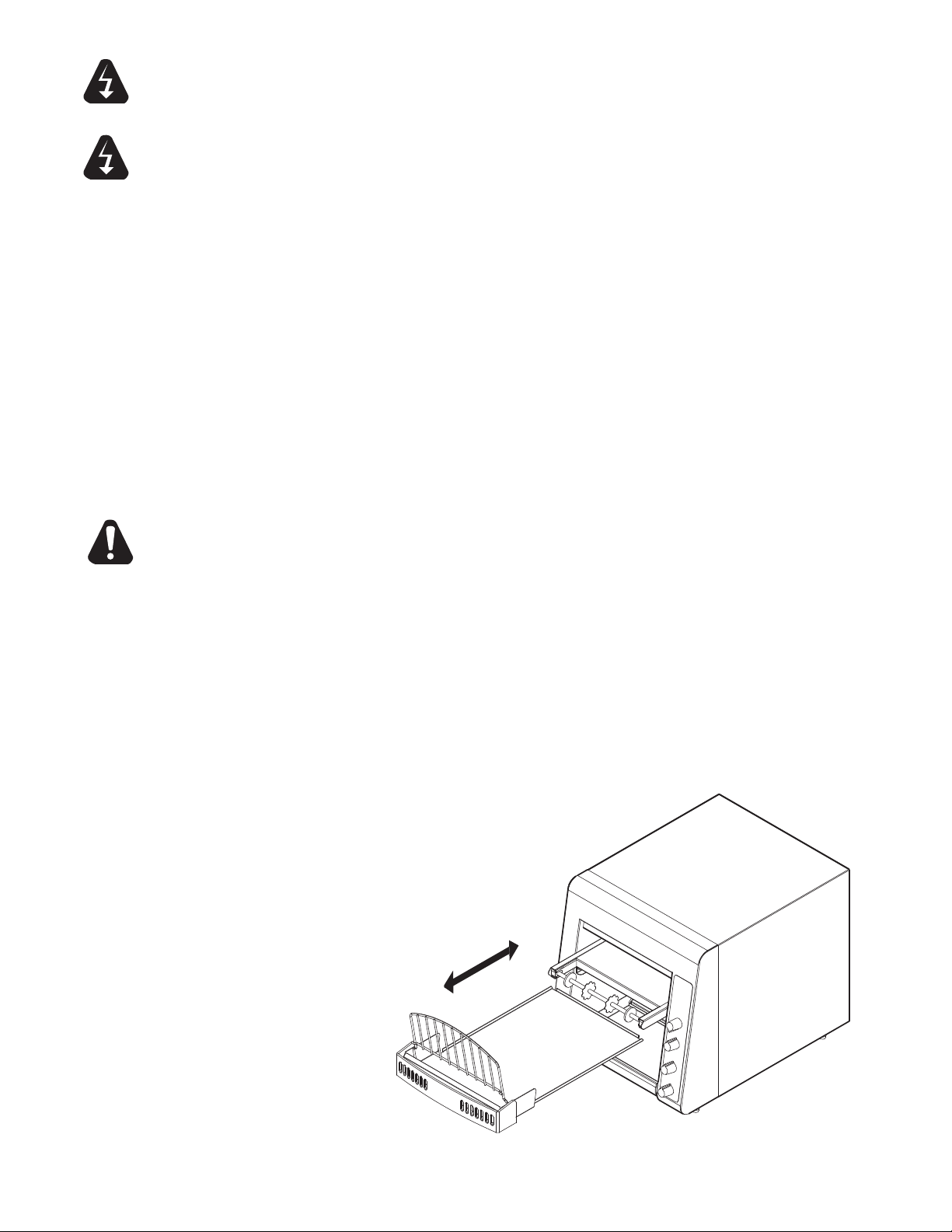
Crumb Tray Removal
4
Page 5

TOASTER COMPONENTS
LOAD UP
CRUMB TRAY
POWER SAVER SWITCH
SPEED CONTROL
FRONT
BOTTOM VIEW
AIR INTAKE FAN
POWER CORD
IL1555
IL1555
DAILY OPERATION
Check the power cord to insure that it is plugged into a proper outlet.
Set the Rotary Power Saver Switch & speed control knob to desired settings.
Always allow 10 minutes of preheat time before loading the unit with product. Failure to allow
sufcient preheat time will result in unsatisfactory cooking until the unit reaches operating
temperature.
OPERATING HINTS AND SAFETY
Disconnect power to the unit with the switch at the end of each day of operation.
Do not leave the unit in operation without an attendant.
Turn Power Saver Switch to Standby during idle periods. It will take only a few minutes to regain
operating temperature.
Do not leave the unit at high temperature when not in use or during idle periods. This will cause food
particles and grease lm to carbonize.
WARNING
CLEANING
Preventive maintenance for your Holman toaster consists of the following recommended cleaning
procedures. To keep your toaster in its top operating condition, these steps should be performed on a
daily or weekly as indicated.
A.
Turn main power saver switch to the OFF position. Disconnect unit from power source.
B. After the unit cools, remove interior crumb tray (as shown on page 4) and clean.
Slide crumb tray back into position.
C.
Wipe exterior surface of unit.
D. Areas inside the toaster, be sure to unplug the unit and allow to cool prior to wiping clean
with a damp cloth.
E. Clean air intake on bottom of unit.
F. For lightly soiled conveyor belts, turn conveyor speed control to fastest setting and
wipe with a damp cloth (daily) For heavily soiled conveyors, turn conveyor speed control
to fastest setting, with crumb tray installed and wipe with a light abrasive pad
(as needed).
DO NOT IMMERSE OR LET THE UNIT STAND IN WATER.
DO NOT HOSE DOWN THE UNIT OR THE TABLE/COUNTER IF THE UNIT IS
ON THE TABLE/COUNTER.
KEEP AWAY FROM RUNNING WATER.
5
Page 6

MAINTENANCE PROCEDURES
1/4”
A. REPLACING HEATER TUBES
1) DISCONNECT UNIT FROM POWER SOURCE.
2) Remove the enclosure, by removing the screws on both the back and bottom of the unit and
lifting the enclosure's back up rst and pulling away from the unit.
3) Remove heater tube wires from terminal block connection, keeping top and
bottom wires separate.
4) Lift heater tube retainers by loosening retaining screws and sliding the retainer plate.
Hand tighten the plate to hold it up so the heater tubes will slide out freely.
5) Gently, pull defective heater tube out of unit.
6) Gently, put new heater tube into unit.
7) Loosen retainer screws and slide the retainer back into place. Tighten the screw to secure the
retainer in place over the ends of the heater tubes.
8) Install the heater tube wires to the terminal block, and reinstall the enclosure.
9) Connect unit to power source and test by toasting some bread after unit has properly reached
operating temperature.
B. REPLACING FAN MOTOR
1) DISCONNECT UNIT FROM POWER SOURCE.
2) Remove the enclosure, by removing the screws on both the back and bottom of the unit and
lifting the enclosure's back up rst and pulling away from the unit.
3) Remove the enclosure and the back panel.
4) Unplug power supply cord from fan motor.
5) Remove (4) screws, which hold fan motor and grill to bottom of unit and remove fan.
6) Put replacement motor and grill in place and secure to the bottom of unit with screws.
7) Reconnect power supply cord to fan motor.
8) Replace back panel and enclosure. Fasten with screws removed in step 2.
C. REPLACING BELT DRIVE MOTOR
1) DISCONNECT UNIT FROM POWER SOURCE.
2) Remove the enclosure, by removing the screws on both the back and bottom of the unit and
lifting the enclosure's back up rst and pulling away from the unit.
3) Remove sprocket from motor shaft, using an Allen wrench and loosening the set-screw.
4) Remove the wire from terminal block connecting the drive motor to internal wiring.
On units rated 208 or 240 volts, note which color leads are being used for these connections
and which lead is capped with white tape. The new motor should use the same arrangement.
5) Remove screws holding motor in place and remove motor from unit.
6) Put new motor in place and attach loosely with mounting screws.
7) Replace sprocket on motor shaft.
NOTE: The two sprockets should line up FLUSH with each other,
so the chain does not twist any during operation.
Also the hub gets installed closets to the motor.
8) Slide motor until the drive chain has about 1/4” slack when
lightly pushed at the center of its top open run.
See chain tensioning illustration.
9) Tighten screws to secure motor.
10) Rewire leads same as removed in step 4.
11) Replace side panel and control box cover.
D. CLEANING AIR INTAKE ONCE A WEEK.
1) DISCONNECT UNIT FROM POWER SOURCE.
2) Place unit on its backside.
3) Use a vacuum cleaner and or a damp cloth to clean
the air intake. This procedure should be done at least once a week.
QCS/RCS Chain Tension
6
Page 7

MAINTENANCE PROCEDURES continued
E. LUBRICATE THE CHAIN & SPROCKETS EVERY 6 MONTHS
1) DISCONNECT UNIT FROM POWER SOURCE.
2) Remove enclosure exposing chain drive.
3) Using an extreme pressure, synthetic chain lubricant with a
temperature range up to 400°F. Apply liberally onto chain
and sprockets. This grease is available as part no. 1P-Z8914.
4) Replace enclosure, Reconnect power source and test unit.
TROUBLESHOOTING GUIDE
A. UNIT WILL NOT HEAT, CONVEYOR BELT WILL NOT MOVE.
1) Be sure the main circuit breaker is switched to the ON position.
2) Check to see if the toaster is plugged in and all controls are turned to the ON position.
3) Call the Star Service Help Desk at 1-800-807-9054.
B. UNIT HAS HEAT ONLY ON ONE SIDE, CONVEYOR BELT TURNS FREELY.
1) Call the Star Service Help Desk at 1-800-807-9054, as heating element may need replacing.
C. CONVEYOR WILL NOT TURN, UNIT HEATS PROPERLY.
To check for mechanical binding:
1) DISCONNECT UNIT FROM POWER SOURCE.
2) Remove 2 screws holding enclosure to the bottom of the unit.
3) Set unit on the legs and remove 4 screws on the back of the toaster.
4) Slide the enclosure off the unit and remove the back panel.
5) Loosen the four screws that hold the drive motor in place.
6) Slide the motor up allowing the drive chain to be removed from the sprockets.
7) Move the conveyor belt by hand to check for mechanical binding.
If conveyor moves freely, call the Star Service Help Desk at 1-800-807-9054, as the drive
motor and/or speed control may need replacing.
8) Replace the enclosure by sliding it forward towards the front of the unit.
The front edge of the enclosure will slide beneath the toaster front.
D. CONVEYOR TURNS AT ONE SPEED REGARDLESS OF SPEED
CONTROL SETTING.
1) Call the Star Service Help Desk at 1-800-807-9054, as speed control MAY need replacing.
E. PRODUCT STICKING TO CONVEYOR OR SLIDE
Your Holman conveyor toaster is designed to toast product that is a current room temperature.
DO NOT attempt to put frozen, refrigerated, or any butter or a butter substitute material in the
toaster. Doing so may cause it to come out doughy or very moist, as well as possibly sticking to
parts of the unit.
1) Follow the cleaning procedures listed on page 5.
7
Page 8

2M-4497-2 12/06
The foregoing warranty is in lieu of any and all other warranties expressed or implied and constitutes the entire warranty.
FOR ASSISTANCE
In all correspondence mention the Model number and the Serial number of your unit, and the voltage or type of gas you are using.
ALL:
* Pop-Up Toasters
* Butter Dispensers
* Pretzel Merchandisers
(Model 16PD-A Only)
* Pastry Display Cabinets
* Nacho Chip Merchandisers
* Accessories of any kind
* Sneeze Guards
* Pizza Ovens
(Model PO12 Only)
* Heat Lamps
* Pumps-Manual
THOROUGHLY INSPECT YOUR UNIT ON ARRIVAL
LIMITED EQUIPMENT WARRANTY
PARTS WARRANTY
SERVICES NOT COVERED BY WARRANTY
PORTABLE EQUIPMENT
10. Voltage conversions
11. Gas conversions
12. Pilot light adjustment
13. Miscellaneous adjustments
14. Thermostat calibration and by-pass adjustment
15. Resetting of circuit breakers or safety controls or reset buttons
16. Replacement of bulbs
17. Replacement of fuses
18. Repair of damage created during transit, delivery, &
installation OR created by acts of God
8
Page 9

1
3
2
4
GREEN
BLACK (BROWN 230V)
FOR 120V
NEMA 5-15P
C
D
FOR 230V
CEE7-7
TOP HEAT
BOTTOM HEAT
WHITE (BLUE 230V)
2
1
4
3
A
B
E
F
LETTER DESCRIPTION
A SWITCH - POWER SAVER
B SPEED CONTROL
C MOTOR - CONVYEOR
D COOLING FAN
E TOP HEATING ELEMENTS
F BOTTOM HEATING ELEMENTS
MODEL:
QCS1-350-120V, CUL15, CUL20, 230V
THIS DRAWING CONTAINS INFORMATION CONFIDENTIAL TO STAR MFG. INT'L. INC.
NO REPRODUCTION OR DISCLOSURE OF ITS CONTENTS IS PERMITTED.
SK2206 Rev -
6/09/2006
9
Page 10

LETTER DESCRIPTION
A SWITCH - POWER SAVER
B SPEED CONTROL
C MOTOR - CONVYEOR
D COOLING FAN
E TOP HEATING ELEMENTS
1
3
2
4
GREEN
BLACK (BROWN 230V)
FOR 120V
NEMA 5-15P
C
D
FOR 230V
CEE7-7
TOP HEAT
WHITE (BLUE 230V)
4
3
A
B
E
NEMA 5-20P
1
5
6
MODEL:
QCS1-500B-120V, CUL20, 230V
THIS DRAWING CONTAINS INFORMATION CONFIDENTIAL TO STAR MFG. INT'L. INC.
NO REPRODUCTION OR DISCLOSURE OF ITS CONTENTS IS PERMITTED.
SK2207 Rev -
6/09/2006
10
Page 11

27
24
1
2
3
4
5
6
7
8
10
7
25
12
13
14
15
16
17
19
21
22
23
29
28
30
36
20
9
Nameplate
18
26
31
32
33
3435
37
38
34
35
39 40 41 42
OPTIONAL ACCESSORY PARTS
39
40
42
41
44
43
MODEL:
QCS1-350/500B-120V CONVEYOR TOASTER
THIS DRAWING CONTAINS INFORMATION CONFIDENTIAL TO STAR MFG. INT'L. INC.
NO REPRODUCTION OR DISCLOSURE OF ITS CONTENTS IS PERMITTED.
SK2212 Rev. - 8/14/2007
11
11
Page 12

Description
Per
Quantity
Part
Number
Fig
No.
34 2R-200752 1 KEYLOCK SPEC KEYED ALIKE_KEY LOCKING ACCESSORY
35 HF-Z9835 1 SECURITY LOCKING COVER_kEY LOCKING ACCESSORY
36 HA-Z9744 1 ELEMENT RETAINER
37 HA-120231 2 HEATER ASSY 350W 60V - TOP 350-120V, CUL20
HA-120233 2 HEATER ASSY 300W 60V-TOP CUL15
HA-120235 2 HEATER ASSY 350W 115V-TOP 230V
QCS1-350-120V, QCS1-500B-120V
Description
Per
Quantity
HA-120237 2 HEATER ASSY 800W 120V-TOP 500B-120V
HA-120238 2 HEATER ASSY 800W 115V-TOP 500B-230V
38 HA-120232 2 HEATER ASSY 450W 60V - BTM 350-120V, CUL20
HA-120234 2 HEATER ASSY 400W 60V -BTM CUL15
HA-120236 2 HEATER ASSY 450W 115V-BTM 230V
500B-120V
NI HA-120242 1 CORDSET ASSY CUL20
NI HA-120244 1 CORDSET ASSY QCS1-230CE
NI HA-120245 1 CORDSET ASSY NEMA 6-20P 230V
39 HF-102215 1 ASSEMBLY BRACKET LEFT_WALL MOUNTING ACCESSORY
40 HF-102214 1 ASSEMBLY BRACKET RIGHT_WALL MOUNTING ACCESSORY
41 HF-100211 1 PLATE ASSY. _WALL MOUNTING ACCESSORY
42 2C-200041 8 SCREW, 1/4-20 X 1/2 SLOT_WALL MOUNTING ACCESSORY
NI HA-120241 1 CORD SET ASSEMBLY QCS-1 350-120V, CUL15,
NI 1P-Z8914 1 EXTREME PRESSURE MULTIPURPOSE SYNTHETIC
GREASE (80°F TO 400°F), TUBE 8oz.
NI 2K-200464 1 BUSHING, WIRE RING 7/8”
ACCESSORIES (Not necessarily sold with unit)
43 WMK-QCS KIT-QCS WALL MOUNT
NI 2K-Y3240 1 BUSHING HEYCO SR 17-2, CORD
44 KLK-QCS1 QCS-1 LOCKING KIT
NI = NOT ILLUSTRATED
Part
Number
Fig
No.
1 HA-Z9786 1 BODY COVER
2 HA-Z9745 1 BACK PANEL
3 2U-200558 1 MOTOR, FAN 120V 15BTL 120V
2U-200560 1 FAN 240V 230V
4 2R-Z8879 1 2-5/8” DIA FAN BLACK CW
5 HA-120240 1 MOTOR ASSEMBLY 120V, CUL20, 350-CUL15
HA-120243 1 MOTOR W/QC ASSY 230V
6 2A-202900 1 SHAFT, DRIVE
7 HA-112261 2 BEARING ASSY, 5/16 TEFLON
8 2P-200645 1 SPROCKET, 25B17 X 5/16”, DRIVEN
9 2P-200646 1 SPROCKET, 25B20 X 5/16”, DRIVE
10 2P-200665 1 CHAIN, 17 1/2” QCS1-350
11 2E-Z9736 2 TERMINAL BLOCK - POWER
12 2R-200562 1 FAN GUARD (OLDER MODELS)
13 2R-200709 4 LEG 1 INCH CHROME PLASTIC
14 HA-Z9743 2 SPRING RETAINER
15 2R-200736 2 2” INCH BEARING SPRING
16 2P-200700 2 BEARING-PTFE SPRING LOADED
17 2A-202904 1 SHAFT, IDLER
18 HN-160020 1 CONVEYOR BELT (10” X 27”)
2B-200601 1 LINK CONVEYOR BELT (10” WIDE)
19 HA-100560 1 TRAY, PULL OUT, QCS 10”
20 HF-101115 1 CRUMB TRAY ASSEMBLY
21 HA-Z9746 1 CRUMB TRAY
22 2R-200787 1 CRUMB TRAY GUARD
23 2B-200763 1 LOADUP, 10 EURO, WIRE
24 2E-Z9737 1 TERMINAL BLOCK - ELEMENTS
25 2C-200149 1 FLAT WASHER 5/16 ID 31NWX H8Z ZINC
26 2A-200284 1 E-CLIP, 5/16”
27 HA-Z9751 1 TOP LINER QCS-1
28 HA-120239 1 SPEED CONTROL ASSEMBLY
29 2E-200551 1 SWITCH ROTARY
30 2M-Z9715 1 FRONT PANEL LABEL
2M-Z9759 1 LABEL - CONTROL QCS1-500B
31 2C-200231 1 PALNUT, HEX, 3/8-24
32 2R-200768 1 KNOB, CONTROL SERIES
2R-200769 1 KNOB, POWERSAVER SERIES
33 2P-200708 2 CAP, KNOB CONTROL
Rev. A 9/30/2010
12
 Loading...