

Page 1
IRRIGA TION CONTROLLER
6 Station Model
INSTRUCTION MANUAL
SUITABLE FOR INDOOR USE ONL Y OTHERWISE
WARRANTY IS VOID
Page 2

T able Of Content s
Features 1
Glossary 2
Programming Instructions
Introduction 3
Programming Example 4
Other Functions 5
General tips for programming 5
Programming
Set Current Time & Correct Day 6
Set Calendar (Optional) 6
Step 1. Set Start T imes 7
Step 2. Set Watering Days 8
Interval Day Selection 8
Individual Day Selection 8
Odd / Even Day Selection 9
Step 3. Set S tation Run T imes 9-10
Manual Operations
System test facility 1 1
Run A Single S tation 1 1
Run A Program 12
Other Features
Stop 12
Stacking S tart Times 12
Automatic BackUp Program 12
Rain Sensor Ready 13-15
Rain Off Mode 16
Water Budgeting 16
Installation Instructions
Mounting The Controller 17
Electrical Hook-Up 17
Field Wiring Connections 18
T erminal Block Layout 18
Power Supply Connections 19
Connection Of V alves 19
Pump Hook-Up Connections 20
Electrical Characteristics 21
Servicing The Controller 22
Fault Finding Guide 23
Spare Watering Planners 24-25
Features
This unit is available as a 6 station configuration.
Designed for residential and light commercial
applications, this controller has four separate programs
with up to sixteen possible start times a day. This
ensures efficient watering of different garden or turf
areas.
These different areas may require individual watering
programs and often use different types of sprinklers.
Examples: Turf areas generally use pop-up sprinklers
and require less frequent but heavier watering. However,
flower beds use micro sprays and require more frequent
watering. The valves (stations) which water similar
garden areas are often grouped together and put into the
same program as they need to be watered on the same
days.
These stations (valves) will water in sequential order
from the lowest number at the start time (or times)
nominated and on the days selected. Maximum watering
duration for a station (valve) is 12 hours and 59 minutes.
This controller has three types of watering day options.
Either, interval watering from everyday to every 15th day,
individual day selection per program, or a 365 day
calendar for ODD/EVEN day watering.
An innovative feature of this controller is the Rain Sensor
Ready (RSR) technology. This allows
to be controlled by a rain sensor. In this way, garden
areas that are subject to rain, can have their irrigation
suspended during wet periods, while areas under cover
can continue to be watered.
individual stations
PAGE 1
Page 3
Glossary
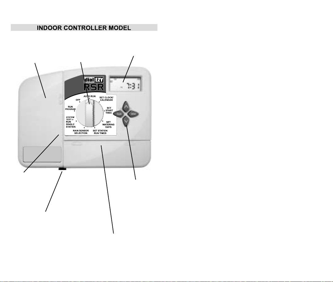
Battery Cover
Remove cover
to fit 9V block
battery.
Fuse
Location
Remove
cover to
access.
Socket & Rubber Plug (RSR)
Rain Sensor Cable Socket.
Simple push in, pull out, plug
& socket configuration.
Compatible with HOLMAN
Rain Sensor
PAGE 2
Selection Dial
Used for
operations &
programming.
(CRS1000BC)
LCD Display
Easy to read
display.
Programming
Buttons
Used for
adjusting the
programmed
information.
Terminal Cover
Remove to access
terminals for
solenoid / valve
wires.
Programming Instructions
Introduction
This controller has been designed with four separate
programs, to allow different garden areas to have their
own individual watering requirements.
A program is basically a method of grouping stations
(valves) with similar watering requirements to water on
the same days. These stations will water in sequential
order from the lowest number at the start time (or times)
nominated and on the days selected.
The key elements when programming
your controller are:
l Grouping the stations. (valves)
Group together garden areas which have similiar
watering requirements. Examples are: Turf Areas,
Flower Beds, Pergola/Undercover Areas, or Vegetables.
These different groups require individual settings.
l Planning out your watering program.
Complete your individual watering planner, supplied at
the back of this book.
l Setting the current time and correct day of the week.
l Setting an automatic program.
Use the following 3 steps to program each group.
1. Set Start(s).
This sets the time of the day when the watering
program will commence.
2. Set Watering Days.
These are the nominated days when the
automatic system will be active.
3. Set Station Run Times.
This sets the watering duration required for each
station (valve).
PAGE 3
Page 4
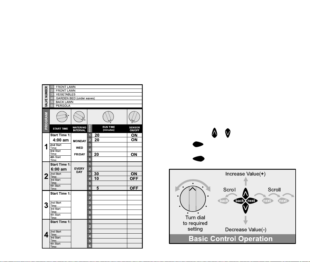
Programming Example
In this example, the lawn areas , Program 1 (Group 1), are
using pop-up sprinklers & require less frequent watering.
The vegetables are being watered using drippers on a
longer run time, with the flower beds, pots, hanging
baskets and pergola areas being watered using micro
sprays. Two stations are not affected by rainfall, these are
individually set to OFF. During rain, these stations are still
watered, whilst the rest of the system is suspended.
Programming InstructionsProgramming Instructions
Other Functions
This controller can also manually run a selected program
once, or an individual station can be set to run once from
1 minute up to 12 hours and 59 minutes. During winter
the automatic programs can be suspended to prevent
watering while it is raining. A test facility for checking the
valves and sprinklers is also provided.
General tips for easy programming
Tips to help eliminate programming confusion.
l Complete the spare watering planner.
l When setting, one push of the button will increment
one unit.
l Holding one button down will fast scroll through units.
l During programming, only the flashing values are able
PAGE 4
to be set, use the
l Pressing
in an orderly sequence.
l Pressing
settings can be changed.
next
back
or buttons.
will scroll forward through the settings
will scroll back to previous settings and
PAGE 5
Page 5
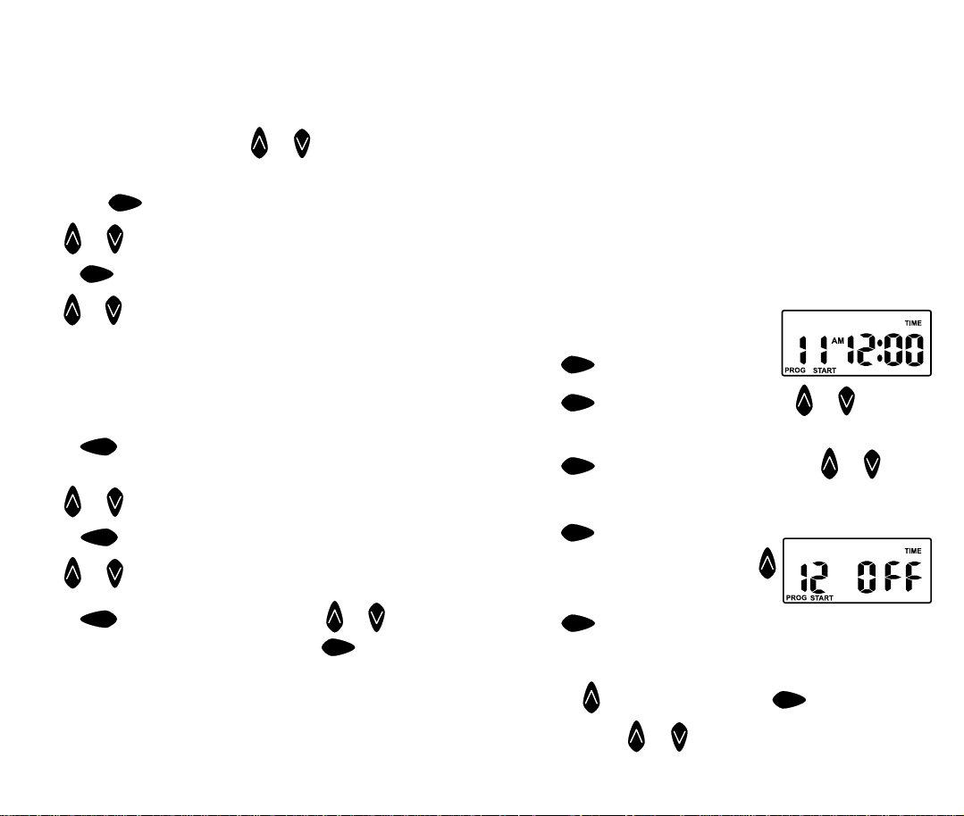
Set Current Time & Correct Day
Turn the dial to Set Clock/Calendar position.
The hour will be flashing. Use
or to adjust.
Note: AM / PM must be set correctly.
Press the
Use
or to adjust.
Press
next
button and the “minutes” will flash.
next
and the “day of the week” will flash.
Use or to set correct day.
Set Calendar (Optional)
Note: The calendar only needs to be set when selecting
ODD/EVEN day watering in areas where water
restrictions may require this feature.
Press
shown. The “year” will be flashing.
Use
Press
Use
Press
adjust. Tip: To return to the clock, press
to another position.
Note: When in the “Auto” position “ODD” or “EVEN” will be
shown.
PAGE 6
button until the year, month and day are
back
or to adjust, if required.
button and the “month” will flash.
back
or to adjust.
and the “day” will flash. Use or to
back
, or turn dial
next
ProgrammingProgramming
Before proceeding, ensure your watering planner has
been completed. From this, you should be aware of
which stations are allocated to each program.
Note: Set one program at a time -This will ensure that
all the values are entered correctly.
SETTING PROGRAM 1 - The program number
can only be set/changed in the Set Start Times position.
Step 1. Set Start Times
All valves will activate in sequential order for each start
time. Turn the dial to Set Start Times and ensure that
“Prog 1” is flashing.
The display will show:
Press
Press
Note: AM / PM is set correctly .
Press
adjust, if required. Each program has up to four start
times and should you require a second start time,
Press
Advance to start 2 by pressing
The display will show.
Press
Tip: To turn an active start time off, turn the dial to the Set
Start times position, Select the start number required
using the button and then press
is flashing. Use
Tip: “OFF” position is between 12 and 1pm.
& “Start 1” willl flash.
next
& the “hour” will flash. Use or to adjust.
next
& the “minutes” will flash. Use or to
next
twice & “Start 1” will flash.
next
.
and proceed as per setting Start 1.
next
until the “hour”
next
or until “OFF” is shown.
PAGE 7
Page 6

Programming
Step 2. Set W atering Days
This unit has interval watering or individual day selection
from everyday to every 15th day or a 365 day calendar
with odd/even day selection in areas where water
restrictions require this feature.
Turn the dial to Set Watering Days.
Interval Day Selection
The display will show:
“Interval 1” will be flashing.
This means that watering will occur every day.
To change the interval day, press the
Examples: Interval 2 means watering will take place every
second day, 3 means watering will take place every third
day etc.
Interval watering can be set from everyday to every 15th
day. The Run Day refers to the number of days
next watering program will occur.
Individual Day Selection
Press the
This is the selectable day option.
This refers to Mon being Day 1. To turn Monday off, press
button
next
The display will show:
button.
before the
Programming
Odd / Even Day Selection (Optional)
In some regions, users are only allowed to water their
gardens on, ODD dates if their house number is ODD, or
on EVEN dates when their number is EVEN .
This controller allows this to be done simply by setting
the relevant selection of ODD or EVEN and setting the
current date into the controller. The controller will account
for leap years.
If you require the ODD / EVEN day option, simply press
the
button and “EVEN” will be shown. This feature may be
required in areas where water restrictions are enforced.
Note: Remember to set the 365 day calendar when
setting the clock, or this feature will be out of sequence.
Step 3. Set Station Run Times
This is the length of time that each station (valve) is set to
water on a particular program. Maximum watering time is
12 hours 59 minutes for each station. A station can be
assigned to 1 or 2 programs if required.
Turn the dial to the Set Station Run Times position and
the display will show the following:
button until “ODD” is shown. Press the
next
next
button. To leave Monday active, leave as is and
advance to Tuesday (day 2) by pressing the
Again press the
followed by
days have been set “on”
PAGE 8
button to set the day off if required
next
to advance. Continue until all seven
or “off” .
next
button.
This means station 1 has a default run time of 10
minutes in program 1. “Station 1” will be flashing.
PAGE 9
Page 7

Step 3. Set Station Run Times. (Continued)
To adjust the Run time in minutes press
or . To set the run time in hours, press
will appear and flash. To adjust use
If not required, press
pressing the button.
Continue until all the stations in Program 1 have been set
with a run time, or if a station (or stations) are not
required to be active in this particular program, ensure
that the run time is set to “OFF”.
Note: To set a station to “OFF”.
Use when the “RUN TIME” is flashing.
This completes the setting up procedure for automatic
watering of Program 1.
Should you need a second program.
Turn the dial to “Set Start Times” and “Prog 1” will flash.
Press
the same 3 steps to set an automatic watering program.
Tip: Remember to return the dial to the “Auto Run”
position after completing the set up of an automatic
program.
This will ensure that the automatic cycles will take place.
PAGE 10
and change to program 2 position and follow
1. Set Starts
2. Set Watering Days
3. Set Station Run Times
and advance to station 2 by
next
or .
next
, and use
and “0”
next
Manual OperationsProgramming
System T est Facility
T urn the dial to System Test or Run Single Station.
(This is a dual function position)
The display will show:
Use this feature to go & check that
your valves & sprinklers are working correctly. The unit
will run all stations in sequential order. The factory preset
time of 2 minutes per station can NOT be adjusted.
IMPORTANT TIP: If the water supply is from a pump
system, it is critical to ensure all outputs are connected to
a valve. Any output NOT connected to a valve, should be
linked back with a wire to the nearest output with a valve.
This prevents the pump running against a closed head.
Run A Single S t ation
Turn the dial to System Test or Run Single Station.
(This will be in the system test mode)
To manually run a single station once,
press button to kick the unit into the
other mode. The display will change
from 2 minutes to 10 minutes.
To adjust the run time, use
To advance to the next station press
next
the
button.
or .
PAGE 11
Page 8

Manual Operations (cont.)
Run A Program
To manually run a complete program once for the run
times as set in the automatic schedule. Turn the dial to
the Run Program position. “Prog 1” will be shown in the
display. To run program 1, leave or advance to program 2
by pressing
the display shows “SEN WET”, the stations set to rain
sensor “ON” will not activate. However, individual stations
can be watered by using the Run Single Station facility.
. Note: if a rain switch is connected and
next
Other Features
Stop
To stop an automatic or manual watering schedule, turn
the dial to the Off position. Tip: For automatic watering,
remember to turn the dial back to the Auto Run position.
The Off position will stop any watering from occuring.
Stacking Start Times
Should you accidently set the same watering start time
on more than one program, the controller will stack them
in sequential order from the lowest number. All
programmed start times will be watered, but the start
times will be shunted along.
Automatic BackUp Program
When the battery is not fitted or is flat, there is a backup
default program in program 1 watering every day at
12:00am for 10 minutes per station.
A standard 9 volt alkaline block battery should be fitted to
the battery snap supplied to maintain the clock accuracy
and hold the automatic programs during power outs.
Tip: The display has a warning indicator to let you know
when the battery is low or not fitted. The word BAT is
displayed under the AM / PM indicator in the clock mode.
PAGE 12
Other Features
Rain Sensor Ready
This feature should only be used when a rain sensor has
been connected. The controller comes pre-fitted with a
socket, ready to take the “HOLMAN” Rain Sensor (P/N
CRS1000BC, not included) which has also been prefitted with a plug. Simply push the plug into the socket
and mount the rain switch, exposing it to direct weather.
Turn the dial to Rain Sensor Selection to enable
individual stations to be rain sensor “ON” or “OFF”
The display will show:
Note: all stations are set to “OFF” at first power up.
The stations set to “OFF” will water automatically at all
times and the stations set to “ON” will be controlled by
the rain sensor. Eg: The stations set to “ON” will not water
automatically with the rain sensor in the “WET” mode. To
set individual stations to “ON” press
advance by pressing
are set “ON” for rain sensor control or “OFF”.
In the “Auto” position, the display
will show:
TIP: If the display is showing “
SENS WET” and you need to
override the rain switch, pull the
plug connected to the “HOLMAN”
Rain sensor.
Note: Both the “System Test” and
“Run Single Station” will work on
all stations regardless of wether
the sensor is wet or dry.
. Continue until all stations
next
button and
PAGE 13
Page 9

Other Features
Rain Sensor Ready (cont.)
DELA Y FEA TURE - When using the Rain Sensor Ready
feature, in conjunction with the rain sensor. It is possible
to set a delay in the controller to stop the automatic
programs from activating too quickly.
This feature is applicable to the stations nominated to be
controlled by the sensor. EG: Set to rain sensor “ON”, and
will only occur when the rain sensor is “WET”.
The reason for this feature is that the rain sensor itself
can dry out due to strong winds or warm temperatures.
Often the sensor will dry out in 24 hours or less and the
automatic watering cycles will start. The soil may still be
too wet in clay or loam situations and it may be desirable
to increase the delay time. This can be set at the
controller.
The delay can be set from 24 hours up to 96 hours and
will prevent any automatic starts from occurring for the
nominated delay period. At the end of the nominated
delay time, the controller will check the rain sensor again
and if it is still reading “SENS WET”, the delay time will
override the automatic watering programs and prevent
any start time from ocurring. This will continue until the
rain sensor is “DRY” and then the automatic programs
will start at the next available start time.
This delay is locked in the controller memory and will
activate any time the Rain Sensor is in the “WET” mode.
NOTE: Stations set at rain sensor “OFF” will continue to
water automatically, and any station can be watered
manually in “system test” or “rain single station” mode.
Other Features
Rain Sensor Ready (cont.)
DELA Y FEA TURE - SETTING RAIN SENSOR DELA Y .
Turn the dial to Rain Sensor Selection.
Press the
The display will show OFF.
This means there is NO delay set for the rain sensor.
The sensor delay will increment in 24 hr blocks, so to set
the required delay, press button & 24 “Sensor Delay
Hrs” will be shown in the display:
If a 48 hr sensor delay is required, press again, a
maximum of 96 hours, (4 days), can be set.
To cancel or clear a rain sensor delay:
Turn the dial to Rain Sensor Selection, press the
button, followed by the button.
The display will show OFF Sensor Delay Hrs.
If a delay period has been set & the rain switch is WET,
the controller display will show
“SEN WET” and will show
the remaining delay time in hours.
This will continue to override the rain sensor until the
delay time has finished counting down, or unless you
clear the delay feature.
back
button.
back
PAGE 14
PAGE 15
Page 10

Other Features
Rain Off Mode
To stop the automatic watering cycles during winter, turn
the dial to the Off position. The word “Off” will appear in
the display. This means the automatic programs will not
come on, but the programmed information is still
retained in the memory. To reactivate the automatic
schedule, turn the dial back to the Auto Run position.
NOTE: If a rain sensor has been connected, the stations
set to rain sensor control, will be turned OFF
automatically, when the sensor is wet.
Water Budgeting
The automatic station run times can be adjusted by
percentage as the seasons change. This will save time
and money as the run times can be adjusted quickly in
spring, winter and autumn to reduce the amount of water
used.
Ensure that the dial is in the Auto Run position and then
press the
The display will show:
Displayed is the word “Budget” and “100%”.
This represents the current automatic watering run times
as being 100%. The percentage budget can be set in
25% increments from 25% up to 150%.
Example: 50% reduces watering by half.
back
and
buttons simultaneously.
next
Installation Instructions
Mounting The Controller
This controller unit is an INDOOR MODEL and MUST not
be exposed to rain or water ingress.
(If the controller needs to be outdoors, you can purchase
a HOLMAN outdoor weatherproof box, P/N COBOX, to
mount the controller inside.This box is available from
your irrigation supplier.)
Install the controller near a 240V AC mains outlet,
preferably located in a house, garage or other covered
area. For ease of operation, eye level placement is
recommended.
Drive one #8 screw into the wall, leaving about 4mm of
the screw exposed. If necessary, use a toggle bolt or
masonary shield.
Hang the controller from the key slot located in the back
of the case. Make sure the head is properly seated inside
the controller case. Additional screws may be inserted
through the holes in the lower corners of the controller
case.
Electrical Hook-Up
WARNING
1 All electrical work must be carried out in
accordance with these instructions following all
applicable Local, State and Federal codes, or
warranty will be void.
To adjust in 25% increments, use
To return to the clock press the
simultaneously. The display will show the word Budget to
indicate that the water budgeting feature is in use.
or buttons.
and
back
next
buttons
2 Disconnect mains power supply before
maintenance work to controller or valves and when
connecting and disconnecting field wiring and
pump or master valve hook-ups.
PAGE 17PAGE 16
Page 11

Installation Instructions
Field Wiring Connections
PREP ARA TION
1 Prepare wires for hook-up by cutting the wires to the
correct length and stripping approximately 6.0mm
(¼ inch) of insulation from the end to be connected to
the controller.
2 Ensure terminal block screws are loosened
sufficiently to permit easy access for wire ends. Insert
stripped wire ends into the clamp aperture and
tighten screws. Do not over tighten as this may
damage the terminal block.
3 A maximum of 0.5 Amps may be supplied by any
output. Check the inrush current of your solenoid coils
before connecting more than two valves to any one
station.
Terminal Block Layout
The terminal block is laid out as follows:
Installation Instructions
Power Supply Connections
The controller itself can run off a 240V AC to 24V AC
external transformer..
It is recommended that the transformer is not connected
to a 240V AC supply which is also servicing or supplying
motors (i.e. Air conditioners, pool pumps, refrigerators,
etc.) Lighting circuits are suitable as a power source.
Connections to the unit are as follows:
Fuse located under battery cover.
GLOSSARY
AC 24VAC Power Supply
COM Common valve wire input
PUMP Master valve or pump start active wire
ST1 to ST6 Station (Valve) active wire connection
Connection Of V alves
Up to two 24VAC Solenoid Valves can be connected to
each station output and wired back to the common (COM)
thus:
Valve wires enter the controller
through the rear
PAGE 19PAGE 18
Page 12

Installation Instructions
Pump Hook-Up Connections
Do not attempt to drive a pump starter directly from the
controller. Pump start is provided by connecting one side
of the coil of a suitable relay to the Master Valve/Pump
Start output of the controller and the other side to the
controller common.
For systems supplied with water from a pump, unused
stations must be connected back to the last used station
to eliminate the possibilty of the pump running against a
closed head. Failure to do so could lead to pump
damage.
The diagram shows an 6 station controller with
stations (valves):
4 active
Unused
stations must
be linked back
to the last
used station.
Electrical Characteristics
Power Supply
MAINS SUPPL Y
This unit can run off a 50Hz external transformer,
(plugpack), with an output of 24VAC 50Hz @ 1 Amp.
Plug Pack Model
The correct wiring installation for the 24VAC plug pack is
shown on page 19. The plug pack model is only suitable
for indoor installation.
Electrical Outputs
ELECTRICAL POWER SUPPL Y
l Input: 24Volts AC 50Hz.
l Electrical Outputs: Maximum of 1.0 AMP
To Solenoid Valves: 24 VAC 50/60 Hz 0.5 AMPs max.
To the Master Valve/Pump S tart: 24VAC 0.25 AMPs
maximum.
Note:
Transformer and fuse capacity must be compatible with
output requirements.
l Overload protection: Standard 20mm 1 Amp fuse.
l Power failure: 9 Volt block type battery maintains
clock and programs for up to 4 weeks.
l The output circuits should be installed and protected
in accordance with wiring rules.
PAGE 21PAGE 20
Page 13

Servicing The Controller
The controller should always be serviced by an
authorized agent.
Follow these steps:
1. Turn mains power off to the controller.
2. Disconnect 24 Volt power leads from the plug pack
at the controller 24VAC terminals.
3. Clearly mark or identify all valve wires according to the
terminals they are connected to, (1 to 6). This allows
you to easily wire them back to the controller,
maintaining your valve watering sequence.
4. Disconnect valve wires from the terminal block.
5. Remove the complete unit from the wall.
6. Carefully wrap the complete unit in protective
wrapping and pack in a suitable box. Return to your
service agent or the manufacturer.
Note: Tampering with the unit will cancel the
Guarantee
7. Replace your controller by reversing this procedure.
Fault Finding Guide
Symptom
No display.
Single Station
not working.
Fuse blows.
No automatic
start.
Buttons on
keypad not
responding.
System
coming on at
random.
More than 1
station coming
on at once.
Pump start
chattering.
Display
cracked or
missing
segments.
Possible Cause
Faulty transformer.
Fuse blown.
Faulty solenoid coil.
Incorrect wiring or bad
wiring joint.
Incorrect
programming or blown
fuse.
Short on keypad or
Programming not
correct.
Short on keypad or
too many start times
entered on automatic
programs.
Damaged main output
driver chip.
Faulty relay or pump
contactor.
Display damaged
during transportation.
Suggestion
Check fuse. Check field wiring.
Check transformer.
Swap faulty station wire on
controller terminal block with
known working station wire. If
the faulty valve still does not
work on the known working
connection then the solenoid coil
is faulty. The panel may need to
be repaired.
Check wiring and joints.
If unit works manually check
programming. Check fuse and
field wiring.
Check instruction book to ensure
programming correct. If keypad
still not responding return panel to
supplier or manufacturer.
Check number of start times
entered on each program. If
programming is correct return
panel to supplier or manufacturer.
Check wiring and swap faulty
station wire(s) on controller
terminal block with known working
station wire. If the same outputs
are still locked on, return panel to
supplier or manufacturer.
Electrician to check voltage on
pump relay or contactor.
Return panel to supplier or
manufacturer.
PAGE 23PAGE 22
Page 14

Sp are W atering Planner
Sp are W atering Planner
PAGE 25PAGE 24
Page 15

Y our Guarantee
The manufacturer Guarantee to the original purchaser that any
product supplied by the manufacturer will be free from defects
in materials and workmanship for a period of three years from
the date of purchase. Any product found to have defects in
material or workmanship within the period of this Guarantee shall
be repaired or replaced by the manufacturer FREE OF CHARGE.
The guarantor does not guarantee the fitness for a particular
purpose of its products and does not make any guarantee,
expressed or implied, other than the guarantee contained herein.
The guarantor shall not be liable for any loss from use of the
product or incidental or consequential damages including
damages to other parts of any installation of which this product
is part.
The guarantee shall not apply to any equipment which is found
to have been improperly installed, set up or used in any way not
in accordance with the instructions supplied with this equipment,
or to have been modified, repaired or altered in any way without
the express written consent of the company. This guarantee
shall not apply to any batteries or accessories used in the
equipment covered under this guarantee or to any damage
which may be caused by such batteries.
If the Controller develops a fault, the product or panel must be
returned in adequate packing with:
1 A copy of your original invoice.
2 A description of any fault.
It is the purchasers responsibility to return the Controller to the
manufacturer or their agent by pre-paid freight.
www.holmanindustries.com.au
463 Scarborough Beach Rd. Osborne Park, 6017, WA.
Ph: +61 8 9204 1011 Fax:+61 8 9204 1013
Email: sales@holmanindustries.com.au
 Loading...