

Page 1
ELECTRIC SPEED
®
IL1493
CONVEYOR OVEN
MODEL
HSCO14 & HSCO16
Installation and
Operation
Instructions
2M-Z11612 Rev. B 4/9/2012
HSCO14
1
Page 2

2
These symbols are intended to alert the user to the presence of
important operating and maintenance instructions in the manual
accompanying the appliance.
RETAIN THIS MANUAL FOR FUTURE REFERENCE
NOTICE
Using any part other than genuine Star factory supplied parts relieves the
manufacturer of all liability.
Star reserves the right to change specications and product design without
notice. Such revisions do not entitle the buyer to corresponding changes,
improvements, additions or replacements for previously purchased
equipment.
Due to periodic changes in designs, methods, procedures, policies and
regulations, the specications contained in this sheet are subject to change
without notice. While Star International Holdings Inc., Company exercises
good faith efforts to provide information that is accurate, we are not
responsible for errors or omissions in information provided or conclusions
reached as a result of using the specications. By using the information
provided, the user assumes all risks in connection with such use.
MAINTENANCE AND REPAIRS
Contact your local authorized service agent for service or required maintenance.
Please record the model number, serial number, voltage and purchase date in the area below and have it ready when
you call to ensure a faster service.
SAFETY SYMBOL
Model No.
Serial No.
Voltage
Purchase Date
Business 8:00 am to 4:30 p.m. Central Standard Time
Hours:
Telephone: (314) 678-6303
Fax: (314) 781-2714
E-mail Parts@star-mfg.com
Service@star-mfg.com
Warranty@star-mfg.com
Website: www.star-mfg.com
Service Help Desk
Authorized Service Agent Listing
Reference the listing provided with the unit
or
for an updated listing go to:
Website: www.star-mfg.com
E-mail Service@star-mfg.com
Mailing Address: Star International Holdings Inc., Company
10 Sunnen Drive
St. Louis, MO 63143
U.S.A
FOR SERVICE IN EUROPE CONTACT:
Middleby Worldwide, Europe
Telephone: +34-94-454-2815
E-mail: mwweurope@middleby.com
2
Page 3

PROBLEMS, QUESTIONS or CONCERNS
Before you proceed consult you authorized service agent directory
or
Call the Technical Service & Parts Department at 314-678-6303.
TABLE OF CONTENTS
Specications . . . . . . . . . . . . . . . . . . . . . . . . . . . . . 4
Oven Components. . . . . . . . . . . . . . . . . . . . . . . . . . . 5
General Information
Electrical Installation
Purchaser's Responsibility
Installation
Location . . . . . . . . . . . . . . . . . . . . . . . . . . . . . . 8
Uncrating & Assembly Instructions . . . . . . . . . . . . . . . 8 - 9
Ventilation & Clearance . . . . . . . . . . . . . . . . . . . . . . 10
Electrical Connection . . . . . . . . . . . . . . . . . . . . . . . 10
Operating & Programming
Manager Lock Modes . . . . . . . . . . . . . . . . . . . . . . . 12
Operation . . . . . . . . . . . . . . . . . . . . . . . . . . . . . 12
Menu Only . . . . . . . . . . . . . . . . . . . . . . . . . . . . . 13
Menu Programming . . . . . . . . . . . . . . . . . . . . . . . . 13
Energy Saving Programming . . . . . . . . . . . . . . . . . . . 13
Bake Time Versus Temperature
Conveyor Speed. . . . . . . . . . . . . . . . . . . . . . . . . . 13
Time of Delivery . . . . . . . . . . . . . . . . . . . . . . . . . . 13
Cleaning Instructions
Daily . . . . . . . . . . . . . . . . . . . . . . . . . . . . . . . . 14
Monthly . . . . . . . . . . . . . . . . . . . . . . . . . . . . . . 14
Annually . . . . . . . . . . . . . . . . . . . . . . . . . . . . . . 14
Nozzle Plate Assemblies . . . . . . . . . . . . . . . . . . . . . 15
Conveyor Belt Tension . . . . . . . . . . . . . . . . . . . . . . 16
Conveyor Belt Link Removal . . . . . . . . . . . . . . . . . . . 16
. . . . . . . . . . . . . . . . . . . . . . . . . . . . . . . 7
. . . . . . . . . . . . . . . . . . . . . . . . . . 6
. . . . . . . . . . . . . . . . . . . . . . . . . . 6
. . . . . . . . . . . . . . . . . . . . . . 6
. . . . . . . . . . . . . . . . . . . . 13
Warranty
Wiring Diagram
Exploded View & Parts List
Main Body Assembly . . . . . . . . . . . . . . . . . . . . . . 20 - 21
Details A, B & C . . . . . . . . . . . . . . . . . . . . . . . . . 22 - 23
Details D & DA. . . . . . . . . . . . . . . . . . . . . . . . . .24 - 25
. . . . . . . . . . . . . . . . . . . . . . . . . . . . . . . . 17
. . . . . . . . . . . . . . . . . . . . . . . . . . . . 18
NOTICE Service on this or any other Holman appliance must be performed by
qualied personnel only. Consult your Authorized Service Agent Directory.
You can call our tech service line at 314-678-6303 or visit our website
www.star-mfg.com for the service agent nearest you.
3
Page 4
E
D
A
C
B
IL1492
HSCO14 HSCO16
A 20.8” (52.8 cm) 22.8” (57.9 cm)
B 9.4” (23.9 cm)
C 17.8” (45.2 cm)
D 30.7” (78 cm) 32.7” (83.1 cm)
E 39.8” (101.1 cm) 41.8” (106.2 cm)
SPECIFICATIONS
Model
HSCO14 208/240V
HSCO16 208/240V
HSCO16P 208/240V
HSCO16P
HSCO16Q 20/22
Voltage Hz Watts Amp Phase Cord Installed Shipping
230V
Electrical Weight
34/38
50/60Hz 15,900
3Ph
NEMA 15-50
154lbs / 70kg 259lbs / 117.7kg
188lbs /
85.5kg
293lbs / 133.2 kg
Recommended Minimum Clearances
Rear of Oven to Wall 0” (0 cm)
Conveyor Extensions to Wall 6” (15.2 cm)
4
2M-Z11612 HSCO TURBO-MAX ELECTRIC SPEED CONV OVEN
Page 5
B
A
C
D
E
F
G I
J
Front
Rear
K
L
H
E
O
M
N
H
IL1508
OVEN COMPONENTS
2M-Z11612 HSCO TURBO-MAX ELECTRIC SPEED CONV OVEN
OVEN COMPONENTS DESCRIPTION
A: Fingers: Projects streams of hot air onto the product.
B: Heat Shutter: Can be adjusted to various settings, depending on product being placed in the
oven, to prevent heat loss.
C: Drive Cog / Drive Collar: This connects the drive motor to the conveyor assembly.
You can disengage the conveyor by simply by pulling back on the drive collar.
This makes for easy removal of the conveyor assembly.
D: Conveyor Assembly: Moves the product through the oven, & is easily removed for cleaning
E: Crumb Tray: Catches crumbs and other material that drops through the conveyor belt.
Located at each end of the conveyor assembly.
F: Cooking Chamber Crumb Tray: Catches crumbs and other material that drops through the
conveyor belt. Located at inside the cooking chamber, under the lower heating elements.
G: Power Switch: Turns the unit on & off.
H: Cooling Air Duckwork: Keeps the front control panel from overheating, the lower duct is
held in by thumb screws, DO NOT operate without ductwork in place.
I: Control Panel: Easy to read Display for easy notication of ovens current operation, and
buttons for making quick modications. Located in front of the oven away from the areas
which may cause burns.
J: Hi-Limit Reset: Monitors inside cooking temperature and will only trip when temperature
reaches above 690°F.
K: Air Intake: Located in the back of the oven. DO NOT BLOCK this area, and wipe it clean on
a regular basis.
L: Conveyor Direction: This switch changes the direction of the conveyor belt.
M: Nameplate: Has specic information regarding this units electrical & gas requirements as
well as the units serial number which is needed for any service that will be required.
This number should be written in the inside cover of this manual and kept for future needs
N: Electrical Input: Electrical Supply connection must meet all national and local electrical
code requirements.
O: Fuse: Easily replaceable fuses, can be serviced easily without tools.
5
Page 6
CAUTION
GENERAL INFORMATION
This equipment is designed and sold for commercial use only by personnel trained and
experienced in its operation and is not sold for consumer use in and around the home nor for
use directly by the general public in food service locations.
First and foremost, each crate should be examined before signing the Bill of Lading to report
any visible damage by the trucker in transit and to account for the proper number of crates.
If there is apparent damage, arrangements should be made to le a claim against the carrier.
Interstate Commerce Regulations require that the claim must be initiated by the consignee.
Proper and secure storage facilities should be arranged for the oven(s) if necessary to protect
it from outdoor or damp conditions at all times before installation.
-IMPORTANT-
When you have all the crates unloaded, open the crates and remove all plastic covers. Inspect
at once for concealed damage. If anything appears to be damaged, contact the appropriate
persons immediately to le a damage claim. After completing this inspection, nish unpacking
the oven. Be sure to remove all paper protection and packing material from the unit
prior to heating.
CAUTION
FOR YOUR SAFETY DO NOT STORE OR USE GASOLINE OR OTHER FLAMMABLE
VAPORS AND LIQUIDS IN THE VICINITY OF THIS OR ANY OTHER APPLIANCE.
INSTALLATION
The ovens are equipped for the voltage indicated on the nameplate mounted on the right side
of the body under the control box. They will operate on alternating current (AC) only. A cord is
provided with a NEMA 6-50 plug. A matching receptacle with 50A supply must be provided.
WARNING
WARNING
DO NOT CONNECT TO DIRECT CURRENT (DC).
The installation of the electric oven should conform to the:
NATIONAL ELECTRIC CODE AND ALL LOCAL ELECTRIC CODES AND
ORDINANCES AND THE LOCAL ELECTRIC COMPANY RULES AND
REGULATIONS.
PURCHASER'S RESPONSIBILITY
It is the responsibility of the purchaser:
1. To see that the electric services for the oven are installed on site in accordance with the
manufacturer's specications.
2. To unload, uncrate, and install the oven in its proper location and in accordance with this
installation operation manual.
3. To see that electric services are connected properly by a qualied installer of your choice.
All such connections must be in accordance with applicable code requirements.
4. To arrange for inspection and operation check-out by an authorized service technician.
2M-Z11612 HSCO TURBO-MAX ELECTRIC SPEED CONV OVEN
6
Page 7

CAUTION
CAUTION
CAUTION
IMPORTANT SAFETY INFORMATION
Do not attempt to operate the oven until connection of utility service has been fully inspected
by an authorized service technician or a Star Service Representative. This service is required
by Star in order to assist the purchaser in proper start-up of the oven on site. Please note the
specic details on the Warranty and make certain that service connections are made to proper
utility services.
The warranty shall not apply if the oven is started up and operated prior to the utilities and oven
being inspected and check-out made by an authorized service technician or a Star Service
Representative.
CAUTION
IMPROPER INSTALLATION, ADJUSTMENT, ALTERATION, SERVICE, OR
MAINTENANCE CAN CAUSE PROPERTY DAMAGE, INJURY, OR DEATH. READ
ALL INSTRUCTIONS THOROUGHLY BEFORE INSTALLING OR SERVICING THIS
EQUIPMENT.
CAUTION
Minimum clearances must be maintained from all walls and combustible materials. Minimum
clearances for this unit should be 0 inches from the rear (rear bumpers provided must be in place)
and 6 inches from both sides. Keep the oven free and clear of all combustible material.
CAUTION
Do not obstruct the ventilation holes in the control panels as these provide cooling air for the
controls.
WARNING
The oven is to be operated only on the type of electricity shown on the specication plate.
WARNING
2M-Z11612 HSCO TURBO-MAX ELECTRIC SPEED CONV OVEN
INSTALLATION INFORMATION
THE INSTALLATION INSTRUCTIONS CONTAINED HEREIN ARE FOR THE USE OF
QUALIFIED INSTALLATION AND SERVICE PERSONNEL ONLY. INSTALLATION OR
SERVICE BY OTHER THAN QUALIFIED PERSONNEL MAY RESULT IN DAMAGE
TO THE OVEN AND/OR INJURY TO THE OPERATOR.
Qualied installation personnel are individuals, a rm, a corporation, or a company which either
in person or through a representative are engaged in and responsible for:
1. The installation of electrical wiring from the electric meter, main control box, or service outlet
to the electric appliance.
Qualied installation personnel must be experienced in such work, familiar with all precautions
required, and have complied with all requirements of state or local authorities having
jurisdiction.
7
Page 8

LOCATION
IL1500
Drive
Collar
Drive
Cog
IL1500
IL1501
CONVEYOR
The well-planned and proper placement of your oven will result in long-term operator conve-
nience and satisfactory performance.
It is essential that an adequate air supply to the oven be maintained to provide a sufcient
ow of ventilation air. Follow these guidelines:
1. Place the oven in an area that is free of drafts.
2. Keep the oven area free and clear of all combustibles such as paper, cardboard, ammable
liquids, and solvents.
3. Do not place the oven on a curb base or seal to a wall. This will restrict the ow of air
and prevent proper ventilation to the blower motors. This condition must be corrected to
prevent permanent damage to the oven.
4. On all models, tripping of the blower motor's thermal overload device indicates an excessive
ambient temperature at the back of the oven. This condition must be corrected to avoid
permanent damage to the oven.
OVEN UNCRATING & ASSEMBLY INSTRUCTIONS
This Turbo-Max Oven comes completely
assembled and ready to use. These
instructions will step you through, removing the
unit from the skid and safely installing the legs,
so not to damage the unit or the installer.
1. Using lift equipment, move oven as close to
nal position as possible.
2. Inspect the oven for any damage which may
have been caused by freight transit or carrier.
If any, see general information section.
3. Remove any packaging from around the unit
or inside the cooking chamber.
4. Disengage the Drive Collar on the Conveyor
to the Drive Cog on the drive motor.
5. Lift and remove Conveyor from the
unit and set aside.
2M-Z11612 HSCO TURBO-MAX ELECTRIC SPEED CONV OVEN
8
Page 9
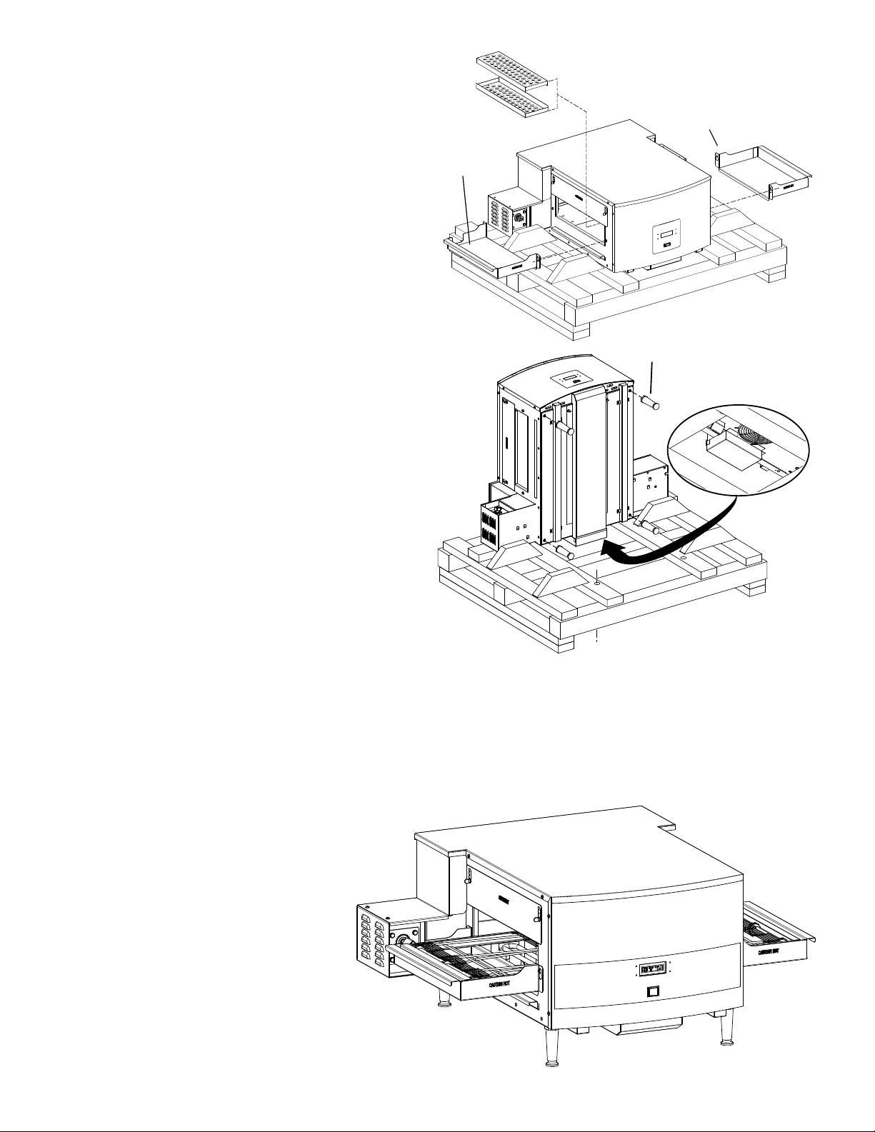
6. Remove the Crumb Trays and set
Crumb Tray Left
Nozzle Plate Assy
Crumb Tray Right
IL1503
IL1502
CAUTION
DO NOT SET DIRECTLY ON
BACK WITHOUT SUPPORT
Legs
Shipping
Restraint
IL1493
aside.
7. Reach into the cooking area and
remove the two Nozzle Plate Assy.
Doing this will prevent them from
being damaged while completing
the unpacking.
8. Unbolt the unit from the skid by
removing the shipping restraints
shown here.
9. The unit weights 110lbs, so with
assistance, lift unit off the skid and
place it on its back using a couple
2 x 4’s.
NOTE: SETTING UNIT DIRECTLY
ON IT BACK, WITHOUT EXTRA
SUPPORT WILL DAMAGE THE
COOLING AIR INLET AND THIS
DAMAGE IS NOT COVERED BY
WARRANTY.
2M-Z11612 HSCO TURBO-MAX ELECTRIC SPEED CONV OVEN
10. Using the legs provided, screw
them into the holes shown here.
11. Set unit back on all four legs and place it into position.
12. Reinstall the nozzle and collumnating plates previously removed.
13. Re-install the crumb trays and conveyor belt assembly.
14. Engage the conveyor belts drive collar and the drive motors drive cog.
15. Assembly is complete.
9
Page 10

IL1506
Control Box
15-50
CAUTION
CAUTION
This unit must be installed on a sturdy counter or
stand using the feet provided for cleaning clearance.
As a minimum, 24" of clearance on the discharge
end of the oven should be allowed for removal of
the conveyor assembly if the oven is not on a mobile
cart. Also allow room for a service technician to
access the control box and the fan motor cover over
the rear of the oven if the oven is not movable.
CAUTION
Any surface the oven is mounted on should have a raised area around the
perimeter to prevent the oven from accidentally sliding off the edge. Serious
injury or death could occur if the oven falls on a person.
CAUTION
Any cart that the oven is mounted on must be deep and wide enough to provide
a stable platform. A cart with a narrow stance could allow the oven to tip over,
causing property damage or serious harm to people.
CAUTION
VENTILATION
Local codes prevail. These are the "authority having jurisdiction" as stated by the National Fire Protection
Association, Inc. in NFPA 96-Latest Edition. For further ventilation information see below.
A ventilation hood may be required to remove heat and cooking odors. The hood and HVAC installation
must meet local codes to gain approval by the authority having jurisdiction. Requirements may vary
throughout the country depending on the location by city, county, and state. Obtain information from the
authority having jurisdiction to determine the requirements for your installation. Obtain information and
review copies of codes or documents that will be used to inspect and approve your installation. Your
ventilation hood supplier and HVAC contractor should be contacted to provide guidance.
CAUTION
Prevent airow through the cooking tunnel. Air must NOT be directed onto the
oven's front or rear or to the sides of the cooking area. This can cause incomplete
or uneven baking and increased energy consumption.
ELECTRICAL CONNECTION
Before making any electrical connections to this unit, check that the power supply is adequate for the
voltage, amperage, and phase requirements stated on the rating plate. A wiring diagram is included
herewith.
When installed, this appliance must be electrically grounded and its installation must comply with the
National Electric Code, ANSI-NFPA 70, latest version, manufacturer's installation instructions, and
applicable local municipal building codes. In Canada, all electrical connections are to be in accordance
with CSA C22.1 - Canadian Electrical Code Part 1 and/or local codes.
WARNING
WARNING
This appliance is equipped with a four-prong (grounding) plug for your protection against
shock hazard and should be plugged directly into a properly grounded three-prong
receptacle. Do not cut or remove the grounding prong from this plug.
10
2M-Z11612 HSCO TURBO-MAX ELECTRIC SPEED CONV OVEN
Page 11

Top
Heat
UP SELECT
ENTER
DOWN
Air
Temperature
Cook
Time
Menu
Program
Call for
Heat
Bottom
Heat
IL1507
CAUTION
OPERATING & PROGRAMMING
SAFETY TIPS
For your safety, read before operating.
In the event of a power failure:
1. Turn all switches off.
2. DO NOT attempt to operate the oven until the power is restored.
General Safety Tips:
1. If the oven needs to be moved for any reason, the power must be disconnected from
the unit before doing so.
2. DO NOT service this unit in any way unless the oven is unplugged.
Manager Lock Modes
There are three different levels to the managers lock, “OFF, MENU ONLY, ON”. To determine what
mode your unit is in, press both the “UP” & “DOWN” buttons and hold for 3 seconds. The current
manager lock mode will be displayed. To change the mode, press the select button, then the enter
button to activate, again to save. You then will be able to choose between: EXIT, which will return you
back to the main menu, or NEXT, will take you into the menu programming.
OFF: There is no lock and operators can access/change/save any of the four control settings.
MENU ONLY: Operator may only toggle between 8 pre-programmed menu choices.
ON: No changes are allowed, the four control settings are locked and the oven will continue operating
at these parameters.
Operation
Push the power switch to “ON”.
When the manager mode set to “OFF” you will be able to change any of the four settings, (top heat,
bottom heat, air temperature & cook time) without affecting the saved
programs. If you happen to set the exact same settings as that of one of your programs, that program
will display to let you know it already exist.
1. Press the upper right button, once to see the current temperature, again to change the current
settings.
2. It will display the current setting for the Top Heat, this can be adjusted by using press the two left
buttons “UP & DOWN”. This can be set between 0 – 100% in 5% increments.
3. Press "SELECT" to continue and do the same for the Bottom Heat.
2M-Z11612 HSCO TURBO-MAX ELECTRIC SPEED CONV OVEN
4. Press "SELECT" to continue and move to “Air Temperature”.
5. The current air temperature setting will be displayed; changes can be made by using the “UP &
DOWN” buttons. Air temperature can be set between 200°F (93°C) to 650°F (343°C).
6. Press "SELECT" to continue to “Cook Time”
7. The current Cook Time or Conveyor Speed is displayed and can be adjusted by using the “UP &
DOWN” buttons. This unit has a Time of Delivery range of 16 seconds to 12 minutes.
8. Enter again to activate.
Above: Control Panel User Interface
11
Page 12

Manager mode set to “Menu Only”
In this mode you will only be able to choose one of 8 pre-determined programs.
1. Press the upper right button, once the see the current temperature, again to view the #1
program.
2. Press "SELECT" to toggle between the eight programs.
3. Press "ENTER" to choose one, again to activate.
MENU PROGRAMMING
Here you will be able to enter each of the 8 programs and change there settings. This mode should only be done
once the settings are tested and proven, and you want to create and save a new program, or re-program new
setting in to one of your existing programs.
1. Press the two left buttons “UP & DOWN”.
2. "ENTER" to continue.
3. Press/Change to Next by pressing "SELECT", then "ENTER" to continue
4. If you ’r e cooking in ° F, t he n "ENTE R" to c ontinue, t o chang e to ° C, press " SELECT",
then "ENTER" to continue.
5. Press/Change to Next by pressing "SELECT", then "ENTER" to continue
6. This takes you to each program, one setting at a time.
7. It will display program #1 setting for the Top Heat, this can be adjusted by pressing the two left buttons “UP
or DOWN”. This can be set between 0 – 100% in 5% increments.
8. Press "SELECT" to continue and do the same for the Bottom Heat.
9. Press "SELECT" to continue to “Air Temperature”.
10. The current air temperature setting will be displayed; changes can be made by using the “UP or DOWN”
buttons. Air temperature can be set between 200°F (93°C) to 650°F (343°C).
11. Press "SELECT" to continue to “Cook Time”
12. The programmed Cook Time or Conveyor Speed is displayed and can be adjusted by using the “UP & DOWN”
buttons. This unit has a Time of Delivery range of 00:16 seconds to 12:00 minutes
13. Press "SELECT" to toggle between the four menu settings, pressing "ENTER" at any time will prompt a “SAVE”,
press "SELECT" to toggle between “YES” and “NO”, "ENTER" to select
14. Change between “EXIT/MGR LOCK/NEXT MENU” by pressing "SELECT".
a. EXIT = Ends programming and takes you to normal operation mode
b. MGR LOCK = Takes you back to the Manager Lock Menu.
c. NEXT = Takes you through the next saved program.
ENERGY SAVING PROGRAMMING
You can use menu programming to manage your energy usage and lower your operating cost,
without compromising you nal product. During slow trafc times, switching to a lower top and bot-
tom heat and a slower cook time, will save your energy cost. These menus can be saved and easily
switched at any moment.
2M-Z11612 HSCO TURBO-MAX ELECTRIC SPEED CONV OVEN
12
Page 13

BAKE TIME VERSUS TEMPERATURE
BAKE vs. DELIVERY TIME
Time to Delivery changes with product
but Bake Time remains constant
at a steady conveyor speed.
20 (BAKE)
28 (DELIVERY)
36 (DELIVERY)
60 sec (BAKE)
80 sec (DELIVERY)
100 sec (DELIVERY)
IL1504
1. Bake time is actually conveyor speed and is dened as the time the product is actually in the oven.
This is measured by noting the time when the leading edge of the product enters the oven and the
time the leading edge of the product leaves the oven. This is adjusted by using the conveyor speed
controller.
2. Bake temperature is adjusted by changing the setpoint of the temperature controller to the desired bake
temperature. When the oven reaches the desired temperature, the red dot in the lower right corner of
the temperature display will turn off and on as the controller maintains the temperature.
3. When establishing a bake time and temperature for a given product, the general rule shall be as the
bake time increases the bake temperature decreases and the reverse is also true; increase temperature,
decrease time. However, there are limits to the above rule. Going to extremes will result in a burnt
exterior and raw interior or it will result in a very light color but over-baked product.
4. Once a good bake has been established, the ne adjustments should be made by holding either the
bake time or bake temperature constant, then varying the other.
CONVEYOR SPEED
Bake Time (Conveyor Speed) - As stated previously, bake time (conveyor speed) is dened as the amount
of time elapsed between the time the leading edge of the product enters the oven and the leading edge of
the product exits the oven. Bake time is controlled by adjusting the digital speed controller. The setting on
the control panel indicates the actual bake time.
Bake time will be the same for any size product.
TIME OF DELIVERY
The time of delivery is the amount of elapsed time between the period when the leading edge of the product
enters the oven and the trailing edge of the product is fully discharged and is ready to be delivered to the
customer.
Time of delivery changes if the product size changes.
Tip: Train yourself not to
pull the product out of the
oven when the leading edge
comes out. Always wait until
the entire product has passed
under the air nozzle holes the product needs this time
to fully bake.
2M-Z11612 HSCO TURBO-MAX ELECTRIC SPEED CONV OVEN
13
Page 14

CAUTION
CAUTION
CLEANING INSTRUCTIONS
Follow this recommended cleaning schedule for proper oven performance:
DISCONNECT THE POWER SUPPLY BEFORE SERVICING OR CLEANING THIS OVEN.
SAFEGUARD THE POWER SO IT CANNOT BE ACCIDENTALLY RESTORED. FAILURE
TO DO SO COULD RESULT IN DISMEMBERMENT, ELECTROCUTION, OR FATAL INJURY.
THERE IS MORE THAN ONE POWER SUPPLY CONNECTION POINT WHEN OVENS ARE
STACKED, SO MAKE SURE THAT ALL SWITCHES ARE IN THE OFF POSITION BEFORE
CLEANING OR MAINTENANCE.
No electrical components should be subjected to moisture. It is therefore important that the oven is wiped
down carefully. NEVER throw buckets of water over the oven or subject it to pressure washing from a
hose or a pressure spray. If water or other liquid is spilled on the oven, make sure that none of it has
entered the control box area before switching the oven ON. If in doubt, call your service company.
CAUTION
Adhere to the following warnings when cleaning or maintaining your conveyor oven:
1. The oven must be cool. Do not use power cleaning equipment, steel wool, or wire brushes on
stainless steel surfaces.
2. Do not use a caustic or an alkaline base cleaner on the interior of the oven.
This will ruin the aluminized nish of the oven interior.
3. When using cleaning solutions, be sure they meet local and national health standards.
DAILY
1. Clean the conveyor belt using a nylon brush. Allow any foreign material to drop into the crumb
pans.
2. Empty and clean the crumb pans. Use a hot water and detergent mix.
Rinse with clean water.
CAUTION
EVERY MONTH (See Oven Components for location)
1. Brush and clean the guard on the motor cooling fan.
2. Unplug the oven.
3. Remove the crumb pans.
4. Remove the conveyor assembly.
5. Remove the Nozzle Assy (outer nozzle plate & inner columnating plate).
6. Clean the oven interior with an appropriate oven cleaner.
7. Clean the conveyor assembly, crumb pans, and other removable components.
Wash in a hot water, detergent mix and rinse with clean water. For difcult cleaning areas, use
a heavy-duty de-greaser or oven cleaner.
8. Move the oven and clean under it. Be careful not to damage the oven's electrical cord or plug
when moving.
9. Remove the cooling air duct if necessary.
DO NOT OPERATE UNIT WITHOUT THE COOLING AIR DUCT IN PLACE, DOING SO
WILL CAUSE THE UNIT TO OVERHEAT AND CAUSE DAMAGE TO THE OVEN.
10. Reassemble the oven, being certain to include both nozzle assemblies
(two parts to each assy) and the cooling air duct..
EVERY TWELVE MONTHS
A factory authorized service person should:
1. Open and clean the inside of the control box.
2. Check and tighten all electrical components.
If maintenance is required, contact your local service company, a factory
representative, or Holman Manufacturing.
2M-Z11612 HSCO TURBO-MAX ELECTRIC SPEED CONV OVEN
14
Page 15

Removing Nozzle Plate Assemblies
Crumb Tray Left
Crumb Tray Right
Crumb Tray Bottom
Cooling Air Duct
Eyebrow
Thumbscrew
IL1497
A
Detail A
NOZZEL PLATE ASSY
IL1505
1. Once cooled, REMOVE conveyor assembly, crumb trays & eyebrows.
2. Reaching into the cooking chamber, lift up on one edge of the nozzle plate assy,
allowing it to be removed from the unit, See Detail A. Repeat for second assy.
3. Separate the assembly and wash in a hot water, detergent mix and rinse with clean water. For
difcult cleaning areas, use a heavy-duty de-greaser or oven cleaner.
Reassemble Nozzle Assemblies
1. Reassemble nozzle assemblies and install in unit.
2. Nozzle assy sit on the rail located at the top of the cooking chamber.
CAUTION
NEVER OPERATE UNIT WITHOUT THE PROPER NOZZLE PLATE ASSEMBLIES
CAUTION
3. Reinstall crumb trays, conveyor & eyebrows, and test unit for proper operation.
PROPERLY INSTALLED.
2M-Z11612 HSCO TURBO-MAX ELECTRIC SPEED CONV OVEN
Above: Removable parts (conveyor not shown),
Right: Nozzle Plate Assy (qty 2) can be easily
removed for cleaning, by simply lifting up on one
edge and allowing it to fall out of place.
15
Page 16

CONVEYOR BELT TENSION
IL1197
Direction
of Travel
CORRECT
inside master link
position
INCORRECT
inside master link
position
IL1198
The conveyor belt of the Turbo-Max Conveyor Oven
does not have a tension adjustment. If the belt becomes
too loose, a link will have to be removed to tighten. A
belt that is too tight will also cause operational problems
due to excessive drag. We suggest that you have a
qualied service technician perform this adjustment.
CAUTION
Careful consideration should be exercised
prior to removing a belt link because a belt
that is too tight will impede the smooth
operation of the conveyor.
CONVEYOR BELT LINK REMOVAL
An entire link can be removed with the conveyor
assembly either in or out of the oven. This may be
necessary as the belt stretches after continuous
use. Following are the necessary steps for removing
links:
1. Move the splice clips to either end of the oven for
easy access.
2. Unhook the splice clips using long nose pliers.
3. Unhook the full link to be removed and slide it out.
Do not discard the link removed as it may be used
for making spare splice clips.
4. Reconnect the inside splice clips.
5. Reconnect the outside splice clips.
6. Replace all parts removed from the oven.
7. Straighten any bent wires to ensure smooth
sprocket engagement.
Remove the outside master links on the right and
left sides of the conveyor belt. Remove the center
splice clips next.
Unhook the end loop and pull up on the link section.
Save this link as it may be used for making splice
clips.
Check the orientation of the splice clips (the hooks
should be up). The belt shown is the top section,
ready for left-to-right travel.
16
Page 17

2M-4497-2 6/1312
The foregoing warranty is in lieu of any and all other warranties expressed or implied and constitutes the entire warranty.
FOR ASSISTANCE
Should you need any assistance regarding the Operation or Maintenance of any Star equipment; write, phone, fax or email our Service Department.
In all correspondence mention the Model number and the Serial number of your unit, and the voltage or type of gas you are using.
ALL:
* Pop-Up Toasters
* Butter Dispensers
* Pretzel Merchandisers
(Model 16PD-A Only)
* Pastry Display Cabinets
* Nacho Chip Merchandisers
* Accessories of any kind
* Sneeze Guards
* Pizza Ovens
(Model PO12 Only)
* Heat Lamps
* Pumps-Manual
Visit our Website at: www.star-mfg.com Email: service@star-mfg.com
THOROUGHLY INSPECT YOUR UNIT ON ARRIVAL
This unit has been tested for proper operation before leaving our plant to insure delivery of your unit in perfect condition. However, there are instances in which
the unit may be damaged in transit. In the event you discover any type of damage to your product upon receipt, you must immediately contact the transportation
company who delivered the item to you and initiate your claim with same. If this procedure is not followed, it may affect the warranty status of the unit.
LIMITED EQUIPMENT WARRANTY
All workmanship and material in Star products have a one (1) year limited warranty on parts & labor in the United States and Canada. Such warranty is limited
to the original purchaser only and shall be effective from the date the equipment is placed in service. Star's obligation under this warranty is limited to the repair
of defects without charge, by the factory authorized service agency or one of its sub-agencies. Models that are considered portable (see below) should be taken
to the closest Star service agency, transportation prepaid.
> Star will not assume any responsibility for loss of revenue.
> On all shipments outside the United States and Canada, see International Warranty.
* The warranty period for the Ultra-Max, Hot Plates, Griddles, Charbroilers is (3) years parts & labor.
* The warranty period for the Star-Max, Charbroilers, Griddles, Hot Plates, Fryers & Finishing Oven is (2) years parts & labor.
* The warranty period for the JetStar six (6) ounce & Super JetStar eight (8) ounce series popcorn machines is two (2) years.
* The warranty period for the Chrome-Max Griddles is ve (5) years on the griddle surface. See detailed warranty provided with unit.
* The warranty period for Teon/Dura-Tec coatings is one year under normal use and reasonable care. This warranty does not apply if damage occurs to
Teon/Dura-Tec coatings from improper cleaning, maintenance, use of metallic utensils, or abrasive cleaners, abrasive pads, product identiers and
point-of-sale attachments, or any other non-food object tha comes in continuous contact with the roller coating. This warranty does not apply to the
“non-stick” properties of such materials.
> This warranty does not apply to "Special Products" but to regular catalog items only. Star's warranty on "Special Products" is six (6) months on parts
and ninety (90) days on labor.
> This warranty does not apply to any item that is disassembled or tampered with for any purpose other than repair by a Star Authorized Service Center or
the Service Center's sub-agency.
> This warranty does not apply if damage occurs from improper installation, misuse, wrong voltage, wrong gas or operated contrary to the Installation and
Operating instructions.
> This warranty is not valid on Conveyor Ovens unless a "start-up/check-out" has been performed by a Factory Authorized Technician.
PARTS WARRANTY
Parts that are sold to repair out of warranty equipment are warranted for ninety (90) days. The part only is warranted, the labor to replace the part is NOT warranted.
SERVICES NOT COVERED BY WARRANTY
PORTABLE EQUIPMENT
Star will not honor service bills that include travel time and mileage charges for servicing any products considered "Portable" including items listed below.
These products should be taken to the Service Agency for repair:
1. Travel time and mileage rendered beyond the 50 mile radius limit
2. Mileage and travel time on portable equipment (see below)
3. Labor to replace such items that can be replaced easily during a daily cleaning
routine, ie; removable kettles on fryers, knobs, grease drawers on griddles, etc.
4. Installation of equipment
5. Damages due to improper installation
6. Damages from abuse or misuse
7. Operated contrary to the Operating and Installation Instructions
8. Cleaning of equipment
9. Seasoning of griddle plates
10. Voltage conversions
11. Gas conversions
12. Pilot light adjustment
13. Miscellaneous adjustments
14. Thermostat calibration and by-pass adjustment
15. Resetting of circuit breakers or safety controls or reset buttons
16. Replacement of bulbs
17. Replacement of fuses
18. Repair of damage created during transit, delivery, &
installation OR created by acts of God
* The Model 510FD, 510FF Fryer.
* The Model 526TOA Toaster Oven.
* The Model J4R, 4 oz. Popcorn Machine.
* The Model 518CMA & 526CMA Cheese Melter.
* The Model 12MC & 15MC & 18MCP Hot Food Merchandisers.
* The Model 12NCPW & 15NCPW Nacho Chip/Popcorn Warmer.
* All Hot Dog Equipment except Roller Grills & Drawer Bun Warmers.
* All Nacho Cheese Warmers except Model 11WLA Series Nacho Cheese Warmer.
* All Condiment Dispensers except the Model HPD & SPD Series Dispenser.
* All Specialty Food Warmers except Model 130R, 11RW Series, and 11WSA Series.
* All QCS/RCS Series Toasters except Model QCS3 & RCS3 Series.
* All Fast Steamer Models except Direct Connect Series.
17
Page 18

®
MODELS:
HSCO14-240V, 50/60 Hz, 3PH, 34/38 Amp, 15,900 Watts
HSCO16-240V, 50/60 Hz, 3PH, 34/38 Amp, 15,900 Watts
HSCO16P-240V, 50/60 Hz, 3PH, 34/38 Amp, 15,900 Watts
THIS DRAWING CONTAINS INFORMATION CONFIDENTIAL TO STAR MFG. INT'L. INC.
NO REPRODUCTION OR DISCLOSURE OF ITS CONTENTS IS PERMITTED.
SK2529 Rev -
8/18/2011
This wiring diagram is a reproduction of a label which was included with the oven.
24Vac
208-240Vac
24Vac
4"
H1
(ON BRACKET INSIDE)
H2
(ON ACCESS DOOR)
H3
F2
BLU
BLK
BRN
33
32
S1
88
1
B2
COMPONENT IDENTIFICATION
WIRE MARKER NUMBERS
COMPONENT MARKING (OPTIONAL, REFERENCE)
MAY BE DIFFERENT ON COMPONENT
C1
5
6
4
3
5
6
3
4
1
2
1
3
5
1
2
3
4
5
6
6
4
2
Y
W
R
GY
BR
BL
GM
C2
S4
1 2
3
4
5
678
GC
01
0403
0201
03
02 04
05
06
07
08
08
1
2
3
PCB
SPEED
0509
10
10
11
11
12
12
14
09
14
30
27
07
464952
46
51
47
5053
4851
54
52
35
37
35
39
38
32
34 36
1
6
36 06
3334
47
50
53
48
49
54
40
45
41
44
42
43
55
56
57
37
F1
P1
CONTACTOR - POWER (ALL HEAT)
--
---
C1
CAPACITOR - FAN
C2
CAPACITOR - GEARMOTOR
F1
FUSEHOLDER/FUSES - 5A
GC
GM
GEARMOTOR
H1
POWER RELAY - TOP HEAT
H2
POWER RELAY - BOTTOM HEAT
H3
CONTACTOR - AIR HEAT
GEARMOTOR CONTROL - OCTAL
S1
RELAY - DPDT 24V COIL
S2
LIMIT SWITCH - COOK TEMP.
S3
LIMIT SWITCH - CONTROLS TEMP.
S4
SWITCH - BELT REVERSING
S5
SWITCH - MAIN
S6
SWITCH - DRAFT
TB
TERMINAL BLOCKS
XF
F2
FAN MOTOR
T/C
THERMOCOUPLE (TYPE K)
PCB
1 2
PWR
ON
7
8
18 19
FAN
+
-
1 2
20
21
TOP
S1
H1
24Vac
5Vdc
+
-
1 2
22
23
BOT
H2
5Vdc
2 1
25
28
AIR
H3
24Vac
S6
C
24
26
27
NO
12
S3
S5
15 16
17
2
1
2M-Z10597
BLK
BLU
(200V use only w/ very poor voltage)
RED(230V use for 208-240V)
J1
J2
J1
J2
J3
J4
P1
P1
1
2
3
4
5
6
S2
1 2
29
29133130
26
S5
4
5
T/C
CN1 T/C TYPR K
YEL(+) RED(-)
SHIELD (SH)
XF
TRANSFORMER
N
J2
N
J2
18
Page 19

®
MODEL:
HSCO16P-230V, 50/60 Hz, 3PH, 34/38 Amp, 15,900 Watts
THIS DRAWING CONTAINS INFORMATION CONFIDENTIAL TO STAR MFG. INT'L. INC.
NO REPRODUCTION OR DISCLOSURE OF ITS CONTENTS IS PERMITTED.
SK2530 Rev -
8/18/2011
This wiring diagram is a reproduction of a label which was included with the oven.
H1
H3
88
1
B2
COMPONENT IDENTIFICATION
WIRE MARKER NUMBERS
COMPONENT MARKING (OPTIONAL, REFERENCE)
MAY BE DIFFERENT ON COMPONENT
5
6
3
4
1
2
1
3
5
1
2
3
4
5
6
6
4
2
Y
W
R
GY
BR
BL
GM
C2
S4
1 234
5 678
GC
01
0403
0201
03
02 04
05
06
07
08
08
1
2
3
PCB
SPEED
0509
10
10
11
11
12
12
14
09
14
24Vac
208-240Vac
30
27
07
46 49 52
46
51
47
50 53
48 51
54
52
37
35
J4
38
34 36
1
6
3606
47
50
53
48
49
54
40
45
41
44
42
43
55
56
57
37
F1
P1
CONTACTOR - POWER (ALL HEAT)
--
---
C1
CAPACITOR - FAN
C2
CAPACITOR - GEARMOTOR
F1
FUSEHOLDER/FUSES - 5A
GC
GM
GEARMOTOR
H1
POWER RELAY - TOP HEAT
H2
POWER RELAY - BOTTOM HEAT
H3
CONTACTOR - AIR HEAT
GEARMOTOR CONTROL - OCTAL
S1
RELAY - DPDT 24V COIL
S2
LIMIT SWITCH - COOK TEMP.
S3
LIMIT SWITCH - CONTROLS TEMP.
S4
SWITCH - BELT REVERSING
S5
SWITCH - MAIN
S6
SWITCH - DRAFT
TB
TERMINAL BLOCKS
XF
F2
FAN MOTOR
T/C
THERMOCOUPLE (TYPE K)
PCB
1 2
PWR
ON
7
8
18 19
FAN
+
-
1 2
20
21
TOP
S1
H1
24Vac
5Vdc
+
-
1 2
22
23
BOT
H2
5Vdc
2 1
25
28
AIR
H3
24Vac
S6
C
24
26
27
NO
12
S3
S5
15 16
17
2
1
24Vac
2M-Z15010
BLK
BLU
(200V use only w/ very poor voltage)
RED
(230V use for 208-240V)
P1
P1
1
2
3
4
5
6
S2
1 2
29
29133130
26
S5
4
5
T/C
CN1 T/C TYPR K
YEL(+) RED(-)
SHIELD (SH)
XF
TRANSFORMER
4"
N
N
J2A
N
L1
L2
L3
F2
BLU
BLK
BRN
33
32
S1
C1
5
6
4
3
35
32
35/36
6J
J2A
J2B
J2B
N1
40
41
42
J3
(ON BRACKET INSIDE)
H2
(ON ACCESS DOOR)
N2
45
44
43
J1
N3
55
56
57
J3
34 33
33/34
37J
19
Page 20

Model: HSCO High Speed Conveyor Oven, Main Assy
®
SK2370 Rev. C 8/23/12
See Detail D
1
2
2
3
6
5
11
15
16
11
13
17
2
18
19
20
11
21
8
20
11
22
23
25
26
27
28
29
43
8
9
32
3334
35
2
2
36
37
37
38
39
40
41
42
2
30
31
24
11
11
14
12
7
8
9
10
4
2
See Detail A
See Detail B
See Detail C
2M-Z11612 HSCO TURBO-MAX ELECTRIC SPEED CONV OVEN
20
Page 21

2M-Z11612 HSCO TURBO-MAX ELECTRIC SPEED CONV OVEN
PARTS LIST April 9, 2012, Rev. B
TURBO-MAX CONVEYOR OVEN, MAIN ASSEMBLY
Fig No Part No Qty Description Application
B6-SC0001
1
B6-SC0032 COVER - SCO 1624 HSCO16
2 2C-200014 36 SCREW 8-32X3/8 THP SS
3 B6-Z10550 1 CONTROL COVER, RIGHT
4 B6-Z10548 1 CONTROL COVER, LEFT
5 B6-Z13421 4 BLOCKOFF PLATE HSCO16P
B6-Z10566
6
B6-Z11793 COL. PLATE, 1624 - FULL HSCO16
B6-Z10565
7
B6-Z11792 NOZZLE , 1624 - FULL HSCO16
8 2C-Z5182 6 SCREW 1/4-20X1/2 THUMB HSCO14
B6-Z11269
9
B6-Z11798 HSCO16
B6-Z10574
10
B6-Z11794 CRUMB TRAY, RIGHT - 1624 HSCO16
11 2C-Z6925 22 SCREW #8X1/2 HEXW B SS
2N-Z10579
12
2N-Z11760 HSCO16
2N-Z11503
13
2N-Z11761 ELEMENT, METAL - TOASTING HSCO16
14 B6-Z11570 6 ELEMENT COVER PLATE
15 2J-Z5189 1 THERMOCOUPLE ASSEMBLY
16 2C-Z3350 3 HALF CLAMP .188 D STL ZP
B6-SC0009
17
B6-SC0037 FRONT PANEL ASSY - 1624 HSCO16
18 B6-Z13422 2 RETURN BLOCKOFF PLATE HSCO16P
B6-SC0014
19
B6-SC0036 CONVEYOR ASSEMBLY - 1624 HSCO16
B6-Z11265
20
B6-Z11797 WIREWAY, BOTTOM - SCO HSCO16
B6-Z10582
21
B6-Z11791 COOLING DUCT, SCO1624
22 2A-Z0314 4 FOOT, 4 IN DIE CAST
23 2C-Y5567 1 SET SCREW 10-24X.125
24 2A-Z8633 1 DRIVE COG
25 2C-Z5555 4 BOLT 1/4-20 X .75 HEX SS
26 2C-Z5557 4 WASHER 1/4 SPLIT SS
27 B5-Z8661 1 GEAR MOTOR COVER PLATE
B6-Z10575
28
B6-Z11795 CRUMB TRAY, LEFT - 1624 HSCO16
B6-Z10511
29
B6-Z11796 CRUMB TRAY, BOTTOM - 1624 HSCO16
30 2U-Z10407 1 GEARMOTOR - 40:1 BROTHER - INCLUDES RUN CAPACITOR
31 B6-Z10596 1 GEARMOTOR FASTENER BRACKET
32 2E-Z10585 1 CORD ASSEMBLY #8 15-50 240V
33 2C-200262 2 NUT, WELD, 1/4 IN.
34 B6-SC0003 1 FAN PLUG ASSEMBLY
35 B6-Z10583 1 ACCESS DOOR, LEFT REAR
36 B6-Z10577 1 ACCESS DOOR, RIGHT REAR
B6-SC0024
37
B6-SC0031 REAR PANEL ASSEMBLY- 1624 HSCO16
B6-SC0041 REAR COVER ASY-HSCO16 230V HSCO16-230V
38 2R-Z11567 1 GUARD, FAN - WIRE
39 2C-Z2594 2 NUT 6-32 HEX W STL NP
40 B6-Z15052 1 TERMINAL BOX ASSY HSCO16-230V
2E-200472 5 TERMINAL BLOCK LG 222 HSCO16-230V
41
2E-200473 1 TERMINAL BLOCK END LG 230 HSCO16-230V
42 B6-Z15055 1 TERMINAL BLOCK COVER HSCO16-230V
43 B6-SC0043 1 DISCHARGE SANDWICH SHELF HSCO16Q-230V
COVER - SCO-1420 HSCO14
1
COL. PLATE, SCO - FULL HSCO14
2
NOZZLE, SCO - FULL HSCO14
2
2 TUNNEL SHROUD (EYEBROW)
CRUMB TRAY, RIGHT HSCO14
1
3 ELEMENT, METAL - AIR HEAT
ELEMENT, METAL - TOASTING HSCO14
6
FRONT PANEL ASSY - 1420 HSCO14
1
CONVEYOR ASSEMBLY HSCO14
1
WIREWAY, BOTTOM - SCO HSCO14
2
COOLING DUCT HSCO14
1
CRUMB TRAY, LEFT HSCO14
1
CRUMB TRAY, BOTTOM HSCO14
1
REAR PANEL ASSEMBLY- 1420 HSCO14
1
21
HSCO14
HSCO14
HSCO16
Page 22

Detail B
Detail C
Detail A
1
3
4
5
4
4
6
4
7
8
9
9.1
9
10
18
19
20
21
22
23
24 25
10
11
12
13
14
15
16
17
2
SK2372 Rev. A
2M-Z11612 HSCO TURBO-MAX ELECTRIC SPEED CONV OVEN
22
Page 23

PARTS LIST August 19, 2011, Rev. B
TURBO-MAX CONVEYOR OVEN DETAILS A, B & C
Fig No Part No Qty Description Application
2B-Z10516-2
1
2B-Z11833-2 HSCO16
2B-Z10516-1 3
2
2B-Z11833-1 5 HSCO16
B6-SC0006
3
B6-SC0035 CONVEYOR WELDMENT - 1624 HSCO16
4 2P-Z5168 4 BEARING, OVEN CONVEYOR
2A-SC0013
5
2A-SC0034 IDLER ASSEMBLY - 1624 HSCO16
2A-Z13691
6
2A-Z13692 DRIVESHAFT ASSEMBLY - HSCO16 HSCO16
7 2P-Z9051 1 SPRING-COUPLING
8 B5-LC0013 1 COUPLING ASSY
B6-SC0022 1 RETAINER DRIVE COG
9
2A-Z13646 DRIVEN COG, UNITS BUILT AFTER 7/2010
9.1 2A-Z13647 ROLL PIN 1/8 X 3/4, UNITS BUILT AFTER 7/2010
10 2U-Z5710 1 HOT AIR BLOWER, 230V - COMES WITH 2E-Z7511 CAPACITOR
11 B6-SC0002 1 FAN PLUG WELDMENT
12 2I-Z10509 1 SEAL, AIR - FAN SHAFT
13 B6-Z10510 1 AIR SEAL RETAINER
14 2C-6349 4 SCREW #8X3/8 B THP STL NP
15 2C-Z5557 4 WASHER 1/4 SPLIT SS
16 2C-Z5555 4 BOLT 1/4-20 X .75 HEX SS
17 1P-E1523 1 TAPE SILICONE TYPE S618
18 2E-Z11661 1 SWITCH, DPST - BLACK
19 2M-Z10597 1 LABEL, DIAGRAM - SCO
B6-Z10532
20
B6-Z11831 FRONT PANEL - SC0 1624 HSCO16
21 2A-Z3429 4 SPACER-NYLON .175X.375X.5
22 2C-Z11541 8 WASHER, FLAT - #6 NYLON
23 PS-Z11960 1 CONTROLLER, SCO
24 2C-Z2594 4 NUT 6-32 HEX W STL NP
2C-2553 4 NUT 6-32 HEX STL NP
25
1 CONVEYOR BELT SEGMENT 72”
BELT CLIP, SINGLE SPACE
CONVEYOR WELDMENT HSCO14
1
IDLER ASSEMBLY HSCO14
1
DRIVESHAFT ASSEMBLY - HSCO14 HSCO14
1
NEEDS 2A-Z13646 & 2A-Z13647
FRONT PANEL - 1420 HSCO14
1
HSCO14
HSCO14
UNITS AFTER: COE3607100001 &
COE4007100001
2M-Z11612 HSCO TURBO-MAX ELECTRIC SPEED CONV OVEN
23
Page 24

Front
Detail D
Detail DA
See Detail DA
1
8
8
9
11
11
REMOVED FOR CLARITY
19
16
20
11
15
11
21
11
15
16
17
18
11
12
10
13
7
34564
2
SK2371 Rev. A
2M-Z11612 HSCO TURBO-MAX ELECTRIC SPEED CONV OVEN
24
Page 25

PARTS LIST August 19, 2011, Rev. B
TURBO-MAX CONVEYOR OVEN DETAIL D & DA
Fig No Part No Qty Description Application
1 2E-Z8628 1 SPEED CONTROL-GEAR MOTOR
2 2E-Z10526 1 SWITCH - SPDT
3 2E-Z8629-1 1 GEARMOTOR, RUN CAPACITOR (SPARE, INCLUDED WITH NEW GEAR MOTOR)
4 2E-Z11662 2 CONTACTOR, 3PH
2K-Y5093
5
2K-Z6183 BUSHING 1.125” DIA HSCO16, HSCO16P
6 2C-Z11577 4 WIRE CLAMP, CUSHIONED
7 2E-Z5711 1 6 MF CAPACITOR (FAN MOTOR) (SPARE, INCLUDED WITH NEW FAN/MOTOR)
8 2C-200067 10 SCREW, 6-32 X 1/4 PHIL TR
9 2T-Z5176 1 THERMOSTAT, 140F UM1854
10 2E-30901-08 2 FUSE HLDR FOR SC FUSE
11 2C-200014 36 SCREW 8-32X3/8 THP SS
12 2E-Z5680 2 FUSE, 5A - CLASS G
13 2T-Z11707 1 HIGH TEMP LIMIT
14 2C-200261 4 NUT WELD 3/8-16 SS
14 2C-Z11707-1 1 NUT HIGH LIMIT
15 2E-Z11514 2 POWER RELAY, HYBRID 3PH
17 2E-Z10563 1 RELAY, DPDT - 24VAC
18 B6-Z10577 1 ACCESS DOOR, RIGHT REAR
19 2E-Z5683 1 SWITCH, DIFF. PRESS.
20 2E-Z9090 1 TRANSFORMER W/BREAKER
21 B6-Z11575 1 POWER RELAY BRACKET
BUSHING-SNAP #SB-1000-12, 1” DIA
4
2M-Z11612 HSCO TURBO-MAX ELECTRIC SPEED CONV OVEN
25
Page 26

Page 27

Page 28

STAR INTERNATIONAL HOLDINGS INC. COMPANY
Star - Holman - Lang - Wells - Bloomeld - Toastmaster
10 Sunnen Drive, St. Louis, MO 63143 U.S.A.
(314) 678-6303
www.star-mfg.com
 Loading...