

Page 1
INSTALLATION NOTES: nBeckon-26
1. Caution and Safety Instructions
• Qualied personnel must install and/or service
product in a manner consistent with its intended
use and in compliance with the National
Electrical Code, Canadian Electrical Code, and/
or all local and provincial codes.
• Follow all product label information and
installation instructions.
• Turn o power at fuse or circuit breaker before
installation or servicing.
• The use of damaged components may cause an
unsafe condition and void product warranty.
• Do not block light emanating from product in whole
or part.
• Never operate the luminaire with missing or
damaged lens. Clean lens on a regular basis.
2. Product Information
• Entire luminaire may become extremely hot. Do
not touch hot lens or luminaire body. Do not touch
the light source at any time.
• Keep all O-rings and sealing surfaces clean during
installation and servicing; failure to do this may
lead to premature failure of the product.
• For installation in pedestrian and pedal cycle
restricted areas.
• Looping connection limited to 24W.
• Basic insulation is provided between dimming input
and mains input.
• Caution, risk of electric shock.
IP
67
3YJ8
• Suitable for ground-mounted recessed only.
• Suitable for wet locations.
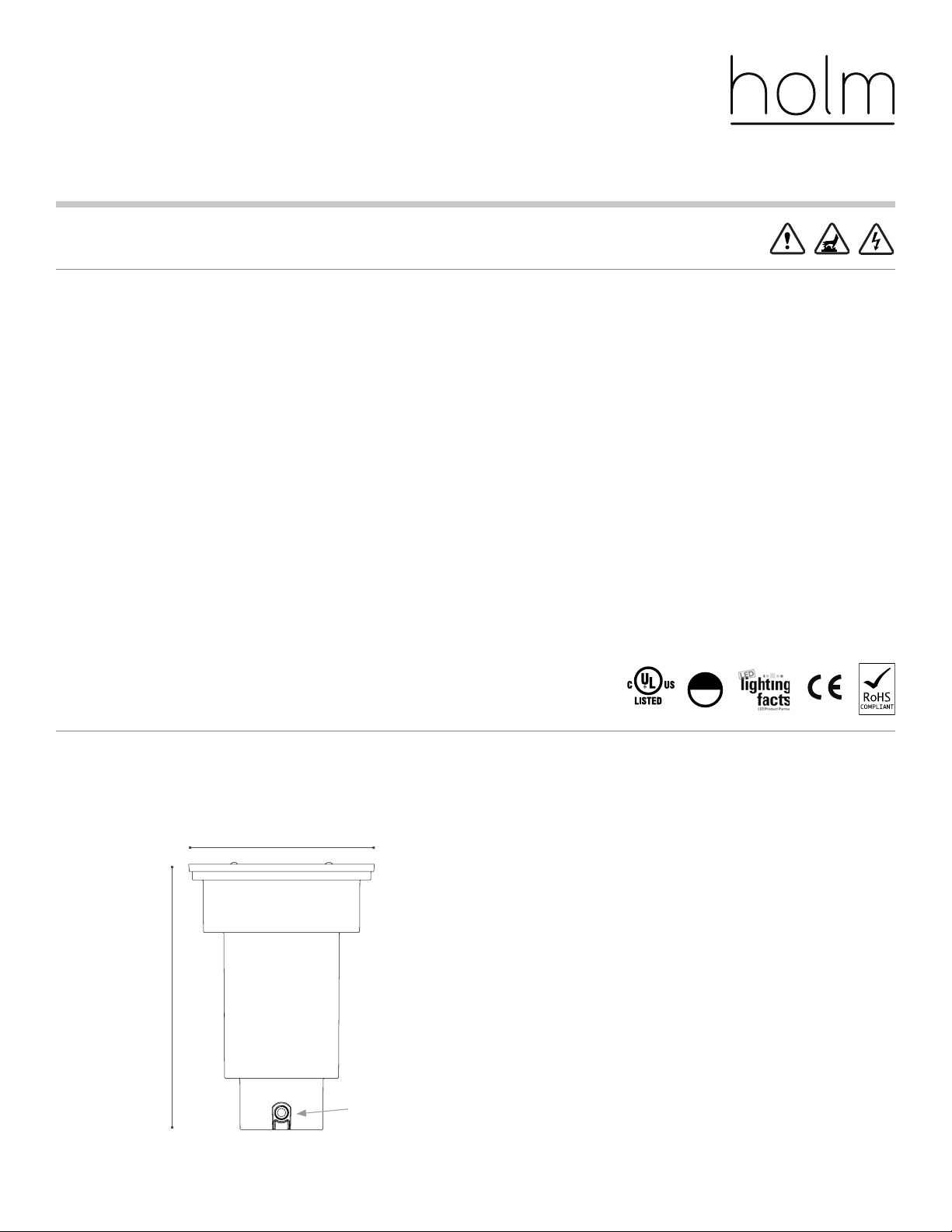
10.5" (267 mm)
15.7" (399 mm)
½"-14 NPT
Knockout (x4)
ARCHITECTURAL & LANDSCAPE LIGHTING | holmlighting.com
Tools Needed:
Installation: Various lengths of 2" x 4"
(50 mm x 100 mm) lumber, ⅛" (3.2 mm)
Allen wrench
Servicing: ⁄" (3.5 mm) Allen wrench, #1 Phillips
screwdriver, #2 Phillips screwdriver
Page 2
INSTALLATION NOTES: nBeckon-26
3. Product Installation
2
Diagrams
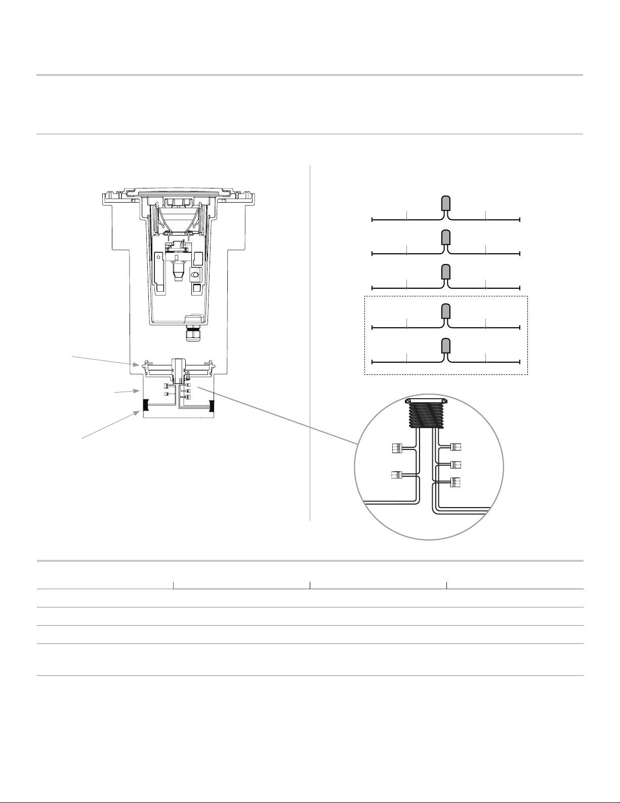
Wiring Compartment
Cover
Wiring Compartment
Threaded Knockouts
Wiring Chart
BUILDING
*For use with 0-10V driver only
Gray
Purple
Ground
Black (HV: Brown)Line/Hot/Switching
White (HV: Blue)Common
Green (HV: Green/
Yellow)
Gray* (HV: Black)0–10V (-)
Purple * (HV: Grey)0–10V (+)
Black
White
Green/Yellow
LUMINAIRE
Power Requirements
Standard Voltage (SV) Universal Voltage (UV) High Voltage (HV)
Input Power 120V/60Hz 110V to 277V/60Hz 220V to 240V/50Hz
Dimming Phase 0–10V 0–10V
Number of Wires 3 5 5
Wire Colors Black, White, Green
ARCHITECTURAL & LANDSCAPE LIGHTING | holmlighting.com
Black, White, Green,
Purple, Gray
Green/Yellow, Brown, Blue,
Gray, Black
Customer Service 1-844-200-4656
Page 3
INSTALLATION NOTES: nBeckon-26
3. Product Installation (continued)
Side ViewSide View Top View
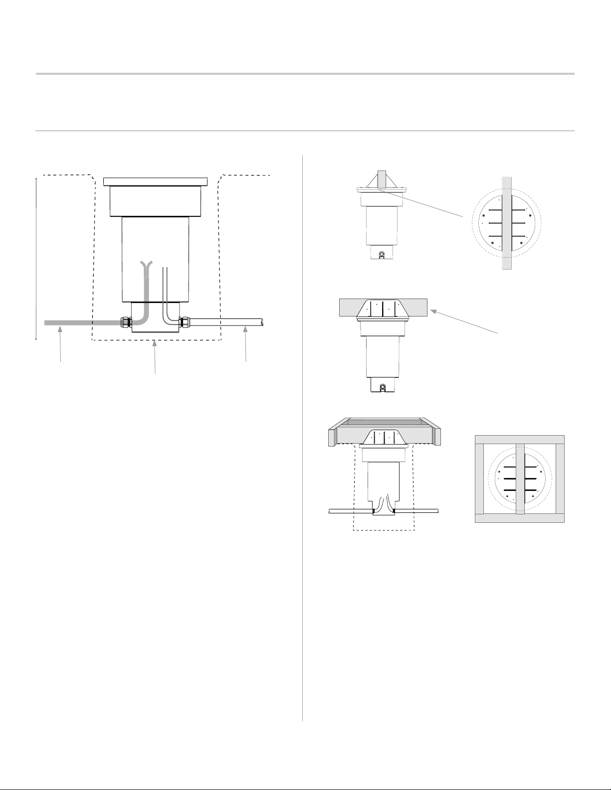
36–42"
(0.9-1 m)
3
2" x 4" (50 mm x 100 mm)
Lumber
Cable Conduit
Bell-Shaped HoleBell-Shaped Hole
1. Excavate a 20" (508 mm) diameter hole in the
desired location.
2. Run conduit or cabling at least 3" (76 mm)
deeper than the bottom of the construction
sleeve (“sleeve”).
3. Choose the ideal knockout(s) to attach conduit
or install cabling and use a tool of choice to
forcefully remove the knockout.
4. For conduit, connect to sleeve with couplings of
choice (½"-14 NPT). For cabling, install with cord
glands and torque to 50 in-lbs (5.6 Nm).
5. Remove the wiring compartment cover and pull
the wiring into the sleeve. Leave the cover inside
the sleeve to prevent loss.
6. Add installation cover onto sleeve using the
provided fasteners.
7. Insert a piece of 2" x 4" (50 mm x 100 mm)
lumber with a length in excess of the excavated
area into the cover’s slot. Secure with metal
fasteners (not provided).
8. Build a wooden frame to align and secure the
construction sleeve during the concrete pour.
9. Ensure the wooden frame aligns the top of the
cover with grade for a ush installation. To install
the faceplate slightly above grade, raise the
frame no more than ⅜" (10 mm).
ARCHITECTURAL & LANDSCAPE LIGHTING | holmlighting.com
Customer Service 1-844-200-4656
Page 4
INSTALLATION NOTES: nBeckon-26
3. Product Installation (continued)
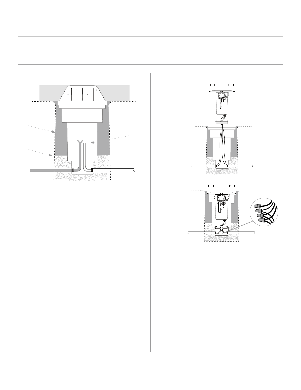
Concrete
12" (300 mm) +
Lead Exposed
Gravel
4
10. Fill hole with gravel ½" (13 mm) higher than the
lower drainage ledge.
11. Pour concrete up to grade.
14. Seal wiring compartment with cover by pressing
in place completely.
15. Place the housing inside the sleeve and rotate
according to the proposed directional of light.
12. Following sucient concrete hardening (curing),
remove wood frame and installation cover.
16. Insert four screws (included) to secure in desired
position with an installation torque value of
13. Run incoming wiring from luminaire housing
50 in-lbs (5.6 Nm).
through the wiring compartment cover. Connect
wiring using the wiring diagram and approved
wire connectors.
ARCHITECTURAL & LANDSCAPE LIGHTING | holmlighting.com
Customer Service 1-844-200-4656
Page 5
INSTALLATION NOTES: nBeckon-26
3. Product Installation (continued)
5
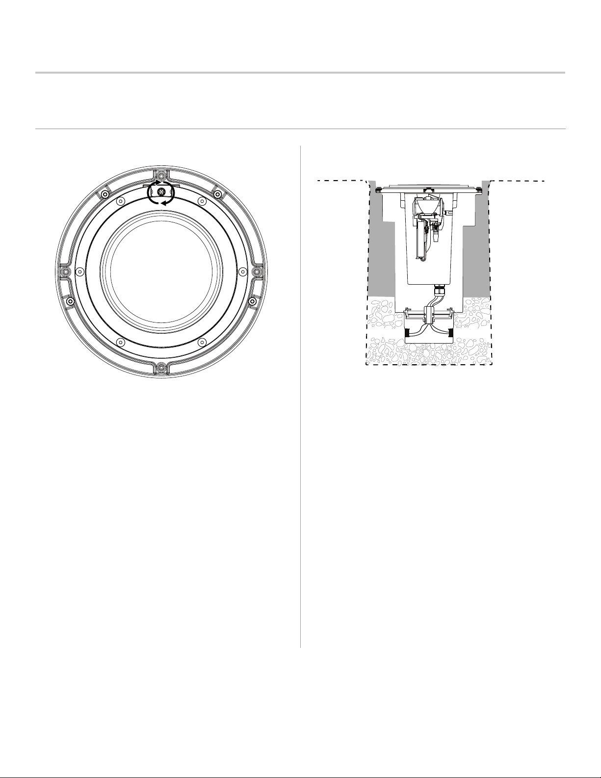
17. Using a #2 Phillips screwdriver, turn the top
adjustment screw to adjust the direction (or
angle) of the LED cartridge. One full turn = 1º.
Use a torque value less than 50 in-lbs (5.6 Nm).
ARCHITECTURAL & LANDSCAPE LIGHTING | holmlighting.com
18. Attach the faceplate and fasten the screws to
secure.
Customer Service 1-844-200-4656
Page 6
INSTALLATION NOTES: nBeckon-26
AAA
7/22/2012
REVISION DESCRIPTION
DRFT
DATE
APVD
A
B
C
D
2
1
DIMENSIONAL
TOLERANCES:
REL.
DATE:
TITLE:
CHECKED
BY:
DESIGNER:
SCALE:
DRAWING NO.
REV.
PRINT
DATE:
UNLESS OTHERWISE SPECIFIED:
SURFACE FINISH:
ALL DIMENSIONS ARE IN INCHES
DO NOT SCALE DRAWING
1:2
BECKON, ASSEMBLY
DIS
21110495XXXX
N/A
ANGLES:
±1°
Hunter Industries
Engineering
1940 Diamond St.
San Marcos, CA 92078
2
1
SHEET 1 OF 1
.XX = ±.01
.XXX = ±.005
.XXXX = ±.0005
THIRD ANGLE PROJ.
C
SIZE:
5/11/2016
DRAWN
BY:
PRODUCT:
MATERIAL:
N/A
THIS DRAWING/DOCUMENT CONTAINS TRADE SECRET INFORMATION OF HUNTER INDUSTRIES, INC. USE, PUBLICATION, AND/OR
DISCLOSURE OF THIS INFORMATION TO THIRD PARTIES ARE ALL PROHIBITED EXCEPT AS EXPRESSLY AUTHORIZED IN ADVANCE BY HUNTER.
NO PATENT LICENSE IS GRANTED TO ANY INVENTIONS DESCRIBED AND/OR ILLUSTRATED HEREIN. ©COPYRIGHT HUNTER INDUSTRIES, INC.
CONFIDENTIAL AND PROPRIETARY
DENOTES FUNCTIONALLY CRITICAL POINTS
DENOTES CRITICAL INSPECTION POINTS
E0000
AAA
7/22/2012
REV
ECO
REVISION DESCRIPTION
DRFT
DATE
APVD
A
B
C
D
1
DIMENSIONAL
TOLERANCES:
REL.
DATE:
TITLE:
CHECKED
BY:
DESIGNER:
SCALE:
DRAWING NO.
REV.
PRINT
DATE:
UNLESS OTHERWISE SPECIFIED:
SURFACE FINISH:
ALL DIMENSIONS ARE IN INCHES
DO NOT SCALE DRAWING
1:2
BECKON, ASSEMBLY
DIS
21110495XXXX
N/A
ANGLES:
±1°
Hunter Industries
Engineering
1940 Diamond St.
San Marcos, CA 92078
3
2
1
SHEET 1 OF 1
.XX = ±.01
.XXX = ±.005
.XXXX = ±.0005
THIRD ANGLE PROJ.
C
SIZE:
5/11/2016
DRAWN
BY:
PRODUCT:
MATERIAL:
N/A
THIS DRAWING/DOCUMENT CONTAINS TRADE SECRET INFORMATION OF HUNTER INDUSTRIES, INC. USE, PUBLICATION, AND/OR
DISCLOSURE OF THIS INFORMATION TO THIRD PARTIES ARE ALL PROHIBITED EXCEPT AS EXPRESSLY AUTHORIZED IN ADVANCE BY HUNTER.
NO PATENT LICENSE IS GRANTED TO ANY INVENTIONS DESCRIBED AND/OR ILLUSTRATED HEREIN. ©COPYRIGHT HUNTER INDUSTRIES, INC.
CONFIDENTIAL AND PROPRIETARY
DENOTES FUNCTIONALLY CRITICAL POINTS
DENOTES CRITICAL INSPECTION POINTS
B
C
D
3
2
1
THIS DRAWING/DOCUMENT CONTAINS TRADE SECRET INFORMATION OF HUNTER INDUSTRIES, INC. USE, PUBLICATION, AND/OR
DISCLOSURE OF THIS INFORMATION TO THIRD PARTIES ARE ALL PROHIBITED EXCEPT AS EXPRESSLY AUTHORIZED IN ADVANCE BY HUNTER.
NO PATENT LICENSE IS GRANTED TO ANY INVENTIONS DESCRIBED AND/OR ILLUSTRATED HEREIN. ©COPYRIGHT HUNTER INDUSTRIES, INC.
CONFIDENTIAL AND PROPRIETARY
B
C
D
3
2
1
THIS DRAWING/DOCUMENT CONTAINS TRADE SECRET INFORMATION OF HUNTER INDUSTRIES, INC. USE, PUBLICATION, AND/OR
DISCLOSURE OF THIS INFORMATION TO THIRD PARTIES ARE ALL PROHIBITED EXCEPT AS EXPRESSLY AUTHORIZED IN ADVANCE BY HUNTER.
NO PATENT LICENSE IS GRANTED TO ANY INVENTIONS DESCRIBED AND/OR ILLUSTRATED HEREIN. ©COPYRIGHT HUNTER INDUSTRIES, INC.
CONFIDENTIAL AND PROPRIETARY
4. Repair/Replacement Instructions
6
Standard Optics ( 20º, 40º, and 60º)
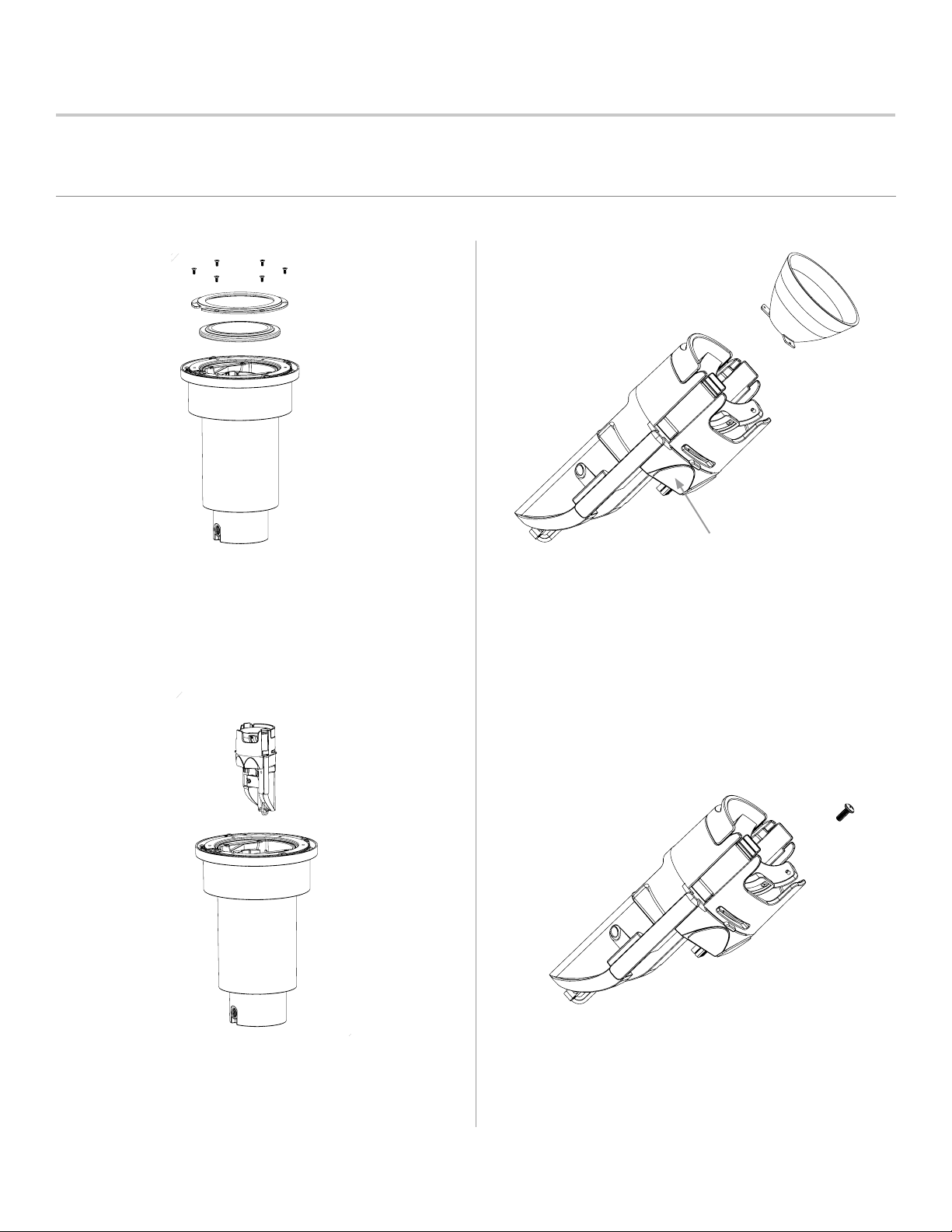
1.
The “non-user replaceable light source” must be serviced by
Hunter-qualied personnel in a manner consistent with its intended use and in compliance with all local and provincial codes.
Unfasten faceplate and housing screws, using a ⅛" (3.2 mm)
Allen wrench. Remove by liing cap upward. Avoid using metal
tools to protect the powder coat nish.
Faceplate and Lens
3.
Note: Do not remove adhesive
thermal pads. Premature
failure may result.
Rotate cartridge arm back into the neutral position.
Twist the optic counterclockwise and pull outward to
remove the optic.
2.
4.
Li cartridge arm and turn counterclockwise to
release lock. Pull complete cartridge out of
luminaire housing.
ARCHITECTURAL & LANDSCAPE LIGHTING | holmlighting.com
Unfasten one screw only inside the cartridge using
a #2 Phillips screwdriver.
Customer Service 1-844-200-4656
Page 7
INSTALLATION NOTES: nBeckon-26
B
C
D
3
2
1
THIS DRAWING/DOCUMENT CONTAINS TRADE SECRET INFORMATION OF HUNTER INDUSTRIES, INC. USE, PUBLICATION, AND/OR
DISCLOSURE OF THIS INFORMATION TO THIRD PARTIES ARE ALL PROHIBITED EXCEPT AS EXPRESSLY AUTHORIZED IN ADVANCE BY HUNTER.
NO PATENT LICENSE IS GRANTED TO ANY INVENTIONS DESCRIBED AND/OR ILLUSTRATED HEREIN. ©COPYRIGHT HUNTER INDUSTRIES, INC.
CONFIDENTIAL AND PROPRIETARY
B
C
D
3
2
1
THIS DRAWING/DOCUMENT CONTAINS TRADE SECRET INFORMATION OF HUNTER INDUSTRIES, INC. USE, PUBLICATION, AND/OR
DISCLOSURE OF THIS INFORMATION TO THIRD PARTIES ARE ALL PROHIBITED EXCEPT AS EXPRESSLY AUTHORIZED IN ADVANCE BY HUNTER.
NO PATENT LICENSE IS GRANTED TO ANY INVENTIONS DESCRIBED AND/OR ILLUSTRATED HEREIN. ©COPYRIGHT HUNTER INDUSTRIES, INC.
CONFIDENTIAL AND PROPRIETARY
D
2
1
THIS DRAWING/DOCUMENT CONTAINS TRADE SECRET INFORMATION OF HUNTER INDUSTRIES, INC. USE, PUBLICATION, AND/OR
DISCLOSURE OF THIS INFORMATION TO THIRD PARTIES ARE ALL PROHIBITED EXCEPT AS EXPRESSLY AUTHORIZED IN ADVANCE BY HUNTER.
NO PATENT LICENSE IS GRANTED TO ANY INVENTIONS DESCRIBED AND/OR ILLUSTRATED HEREIN. ©COPYRIGHT HUNTER INDUSTRIES, INC.
CONFIDENTIAL AND PROPRIETARY
B
C
D
3
2
1
THIS DRAWING/DOCUMENT CONTAINS TRADE SECRET INFORMATION OF HUNTER INDUSTRIES, INC. USE, PUBLICATION, AND/OR
DISCLOSURE OF THIS INFORMATION TO THIRD PARTIES ARE ALL PROHIBITED EXCEPT AS EXPRESSLY AUTHORIZED IN ADVANCE BY HUNTER.
NO PATENT LICENSE IS GRANTED TO ANY INVENTIONS DESCRIBED AND/OR ILLUSTRATED HEREIN. ©COPYRIGHT HUNTER INDUSTRIES, INC.
CONFIDENTIAL AND PROPRIETARY
B
C
D
3
2
1
THIS DRAWING/DOCUMENT CONTAINS TRADE SECRET INFORMATION OF HUNTER INDUSTRIES, INC. USE, PUBLICATION, AND/OR
DISCLOSURE OF THIS INFORMATION TO THIRD PARTIES ARE ALL PROHIBITED EXCEPT AS EXPRESSLY AUTHORIZED IN ADVANCE BY HUNTER.
NO PATENT LICENSE IS GRANTED TO ANY INVENTIONS DESCRIBED AND/OR ILLUSTRATED HEREIN. ©COPYRIGHT HUNTER INDUSTRIES, INC.
CONFIDENTIAL AND PROPRIETARY
4. Repair/Replacement Instructions (continued)
7
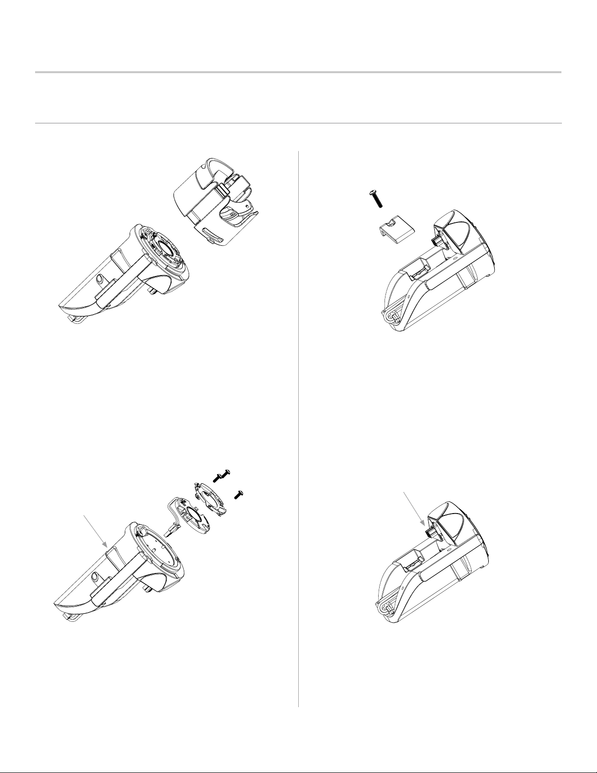
5.
Twist and rock the upper cartridge component
to remove top portion.
7.
Remove the driver clamp using a
#2 Phillips screwdriver.
6.
8.
NOTE: Remove adhesive label/cover from the
side of the cartridge to expose driver wiring.
Disconnect wire connectors between the
driver and the LED module before completely
removing the LED module.
Unfasten three LED module screws using #1 Phillips
screwdriver. Remove reector adapter ring and LED
Push black, six-pin connector downward to unlock it
from the cartridge.
module from cartridge platform.
ARCHITECTURAL & LANDSCAPE LIGHTING | holmlighting.com
Customer Service 1-844-200-4656
Page 8
INSTALLATION NOTES: nBeckon-26
B
C
D
3
2
1
THIS DRAWING/DOCUMENT CONTAINS TRADE SECRET INFORMATION OF HUNTER INDUSTRIES, INC. USE, PUBLICATION, AND/OR
DISCLOSURE OF THIS INFORMATION TO THIRD PARTIES ARE ALL PROHIBITED EXCEPT AS EXPRESSLY AUTHORIZED IN ADVANCE BY HUNTER.
NO PATENT LICENSE IS GRANTED TO ANY INVENTIONS DESCRIBED AND/OR ILLUSTRATED HEREIN. ©COPYRIGHT HUNTER INDUSTRIES, INC.
CONFIDENTIAL AND PROPRIETARY
4. Repair/Replacement Instructions (continued)
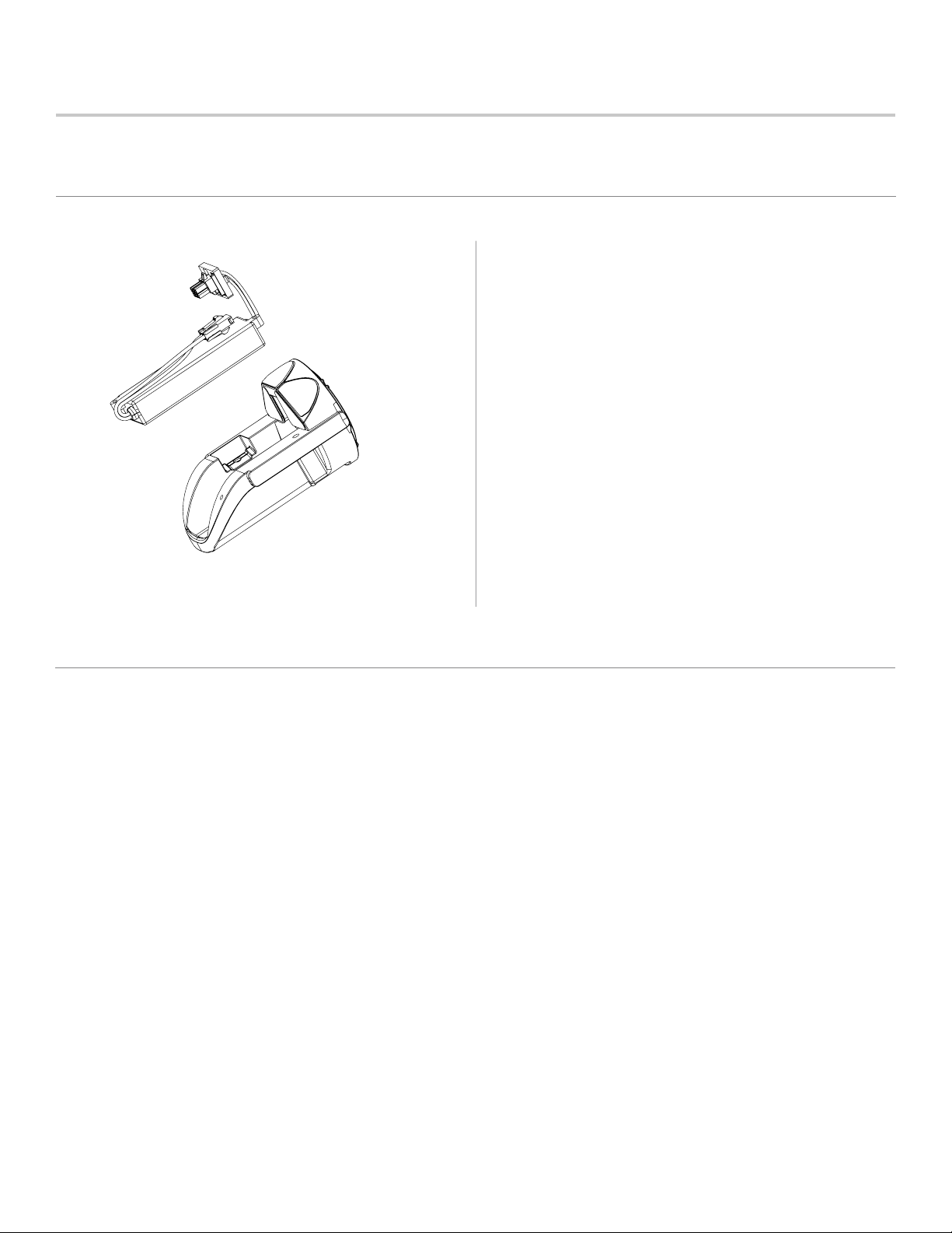
9.
8
Remove driver from cartridge.
5. Warranty
STATEMENT OF LIMITED WARRANTY
Hunter Industries Incorporated (“Hunter”) warrants Holm lighting products to be free of defects in materials or workmanship
under normal use for a period of ve (5) years from the date of invoice. If a defect in a Holm product is discovered during the applicable
warranty period, Hunter will repair or replace, at its option, the product or the defective part. This limited warranty does not extend to
repairs, adjustments, or replacement of Holm products or parts resulting from misuse, negligence, alteration, modication, tampering,
or improper installation and/or maintenance of the product. This warranty extends only to the original installer of the product. If a
defect arises in a Holm product or part during the warranty period, contact the local authorized manufacturer’s representative. Hunter’s
obligation to repair or replace its products as set forth above is the sole and exclusive warranty set forth by Hunter. There are no other
warranties, expressed or implied, including warranties of merchantability and tness for a particular purpose. Hunter will not be liable to
distributor or any other party in strict liability, tort, contract, or any other manner for damages caused or claimed to be caused as a result
of any design or defect in Holm products, or for any special, incidental, consequential, or exemplary damages or any nature, including
without limitation lost business or prots. Notwithstanding the foregoing, if for any reason Hunter is found to be liable, in no event shall
Hunter’s liability exceed the price of the product which gives rise to the claim, loss, or damage.
If you have any questions concerning the warranty or its application, please write to:
Customer Service Department, Holm
1940 Diamond Street
San Marcos, CA 92078, U.S.A.
ARCHITECTURAL & LANDSCAPE LIGHTING | holmlighting.com
Customer Service 1-844-200-4656
HOLM-045-IN-nBeckon-EN C 5/19
 Loading...